Door Locks - Power - CelicaTech
Door Locks - Power - CelicaTech
Door Locks - Power - CelicaTech
Create successful ePaper yourself
Turn your PDF publications into a flip-book with our unique Google optimized e-Paper software.
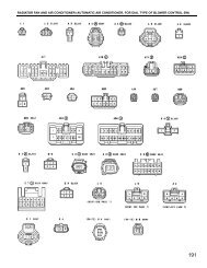
Locate power door lock control relay. Ensure control relay16-pin connector is connected. Using voltmeter positive lead,backprobe Blue/Red wire terminal of connector. Using voltmeternegative lead, backprobe Blue/White wire terminal of connector. Ensurevoltage increases from zero to battery voltage for approximately 0.2second with door lock manual switch in UNLOCK position. Reversevoltmeter leads and ensure voltage increases from zero to batteryvoltage for approximately 0.2 second with door lock manual switch inLOCK position. If voltage does not change as specified, replace powerdoor lock control relay and retest system.POWER DOOR LOCK CONTROL RELAY CIRCUIT TESTING CHARTSNOTE:NOTE:<strong>Power</strong> door lock ECU or control relay circuit test charts areprovided to pinpoint a malfunctioning circuit. Checking pinvoltages at power door lock ECU or control relay connectorswill help determine if power door lock ECU and control relayare receiving and sending proper voltage signals. Using testcharts may also help determine if there is a short or openin harness or connectors.Unless stated otherwise in testing procedures, perform allvoltage tests using a Digital Volt-Ohmmeter (DVOM) with aminimum 10-megohm input impedance. Voltage readings may varyslightly due to battery condition or charging rate.Fig. 2: <strong>Power</strong> <strong>Door</strong> Lock Control Relay Circuit ConnectorCourtesy of Toyota Motor Sales, U.S.A., Inc.


