J2 625 Integrated Touch Screen Computer System Manual - Size
J2 625 Integrated Touch Screen Computer System Manual - Size
J2 625 Integrated Touch Screen Computer System Manual - Size
- No tags were found...

Create successful ePaper yourself
Turn your PDF publications into a flip-book with our unique Google optimized e-Paper software.
Copyright © 2012 <strong>J2</strong> Retail <strong>System</strong>s LtdAll rights reservedChange historyVersion 0.0 Release June 7, 2012Version 0.1 Release June 15, 2012<strong>J2</strong> <strong>625</strong> <strong>System</strong> <strong>Manual</strong>Version 0.1 June15, 2012 (Draft)2
ContentsOverview ............................................................................................................................ 6Specifications <strong>J2</strong> <strong>625</strong> ......................................................................................................... 8<strong>J2</strong> <strong>625</strong> <strong>Integrated</strong> <strong>Touch</strong> <strong>Screen</strong> <strong>Computer</strong> .................................................................. 10I/O Ports ........................................................................................................................ 10Off / On Button ............................................................................................................. 10Hard Disks .................................................................................................................... 10<strong>Touch</strong> <strong>Screen</strong> ................................................................................................................ 11<strong>System</strong> Board ................................................................................................................ 12<strong>J2</strong> <strong>625</strong> Display ............................................................................................................... 12Secondary Video Port ................................................................................................... 13Ethernet Connection ...................................................................................................... 13Serial ports .................................................................................................................... 14USB Ports ...................................................................................................................... 16Audio ............................................................................................................................. 16Power Supply ................................................................................................................ 17+12VDV Power Out ..................................................................................................... 17Cash Drawer Ports ........................................................................................................ 17CMOS Clear .................................................................................................................. 19Mini PCI-E .................................................................................................................... 19Memory SODIMM(s) ................................................................................................... 20Typical Power Consumption <strong>J2</strong> <strong>625</strong> ............................................................................. 20Service .............................................................................................................................. 21Removing the Head from the Base ............................................................................... 21Removing the Power Supply ........................................................................................ 22VESA Mounting ........................................................................................................... 23Removing the Back Cover ............................................................................................ 24Changing the <strong>System</strong> Board .......................................................................................... 25Adding Memory ............................................................................................................ 26BIOS Setting .................................................................................................................... 27Main <strong>Screen</strong> .................................................................................................................. 27<strong>System</strong> Information ....................................................................................................... 27Advanced <strong>Screen</strong> .......................................................................................................... 28Boot Configuration ....................................................................................................... 28Power Configuration ..................................................................................................... 29COM Power and LCD Brightness Configuration ......................................................... 29Security <strong>Screen</strong> ............................................................................................................. 30Boot <strong>Screen</strong> ................................................................................................................... 30Exit <strong>Screen</strong> .................................................................................................................... 31Phoenix Secure Core Tiano BIOS ................................................................................ 31<strong>J2</strong> <strong>625</strong> <strong>System</strong> <strong>Manual</strong>Version 0.1 June15, 2012 (Draft)3
Fingerprint Reader / MSR ............................................................................................. 51iButton / MSR .................................................................................................................. 51<strong>625</strong> UPS ............................................................................................................................ 51RFID ................................................................................................................................. 51Pole Mount Options ........................................................................................................ 51Contact Information ....................................................................................................... 52European Office ............................................................................................................ 52USA Office ................................................................................................................... 52Australian Office ........................................................................................................... 52Website ......................................................................................................................... 52<strong>J2</strong> <strong>625</strong> <strong>System</strong> <strong>Manual</strong>Version 0.1 June15, 2012 (Draft)5
<strong>J2</strong> <strong>625</strong> <strong>System</strong> <strong>Manual</strong>Version 0.1 June15, 2012 (Draft)7
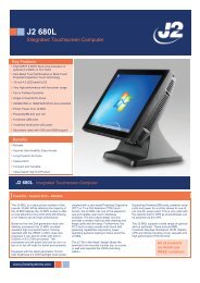
Specifications <strong>J2</strong> <strong>625</strong>CPU and ChipsetProcessorChipset I/OMemoryExternal PortsSerial PortsUSB PortsEthernetCash Drawer PortsSecondary VideoDual Core Intel Atom D2550 1.86GHz with 1MB Cache, 4 threadswith <strong>Integrated</strong> GMA 3650 Graphics controllerNM102 X DDR3 SO-DIMM, 4GB max, 2GB standard, 1067MHz4 RS-232 RJ45 with power +12V BIOS controlled6 USB 2.0, 5 in cable well 1 on side of unit10/100/1000 MHz Ethernet port with status LEDs on connector1 RJ11 support 2 cash drawers +24V and +12V, Dual status linesDisplay Port with DVI, HDMI and VGA support+12 Power +12 Volt power out for secondary video display or other deviceAudioInternal I/OStorageLCD Panel<strong>Touch</strong> <strong>Screen</strong>USBMSRMini PCI-ExpressOptional PeripheralsMSRiButtonFingerprint ReaderRFID2-in-12-in-1Second DisplayCustomer DisplayUPSWirelessPoweredUSB HUBCombo Audio Jack for headset or headset with microphoneOne 3Gb/s SATA Port onboard, slide in/out 2.5“ HDD or SSD15 inch 1024 x 768 250cd/m 2 panelResistive True Flat or Projective Capacitive with Multi-touch and gesturing3 onboard USB ports for optional devices, MSR, Wi-Fi, PCTOnboard microcontroller of MSR on PS2Mini PCI Express slot for 802.11 b/g/n WiFi card and other functions3 TrackDallas Key iButtonUSB Digital Persona Fingerprint Reader125KHz RFID USBMSR 3 track / Finger PrintMSR 3 track / iButton4:3 displays, 8.4”, 10.4” or 12.1” with or without touch16:9 displays, 10.1” or 14” with or without touch2x20 VFD or 2x20 LCM<strong>J2</strong> Micro UPS 30minute run timeor <strong>J2</strong> Universal UPS with 2.5 hour run time802.11 b/g/n Mini PCI Express card with internal antennasExternal PoweredUSB Hub with 1 +24V, 7 +12V PoweredUSB and 6powered serial ports and optional internal UPS<strong>J2</strong> <strong>625</strong> <strong>System</strong> <strong>Manual</strong>Version 0.1 June15, 2012 (Draft)8
EnvironmentalOperating Temp. 0-45cEMICE / FCC Class ASafetyLVD external adaptor UL c/us, CE, TUV, othersDust & WaterIP 64 front of unit, IP 54 whole unitPower100-240V 50-60Hz 19VDC 65 watts power supplyWeight8kgDimensionsWith base attached: 37x28x35cm, 14.6”x11.0”x13.8”<strong>J2</strong> <strong>625</strong> <strong>System</strong> <strong>Manual</strong>Version 0.1 June15, 2012 (Draft)9
<strong>J2</strong> <strong>625</strong> <strong>Integrated</strong> <strong>Touch</strong> <strong>Screen</strong> <strong>Computer</strong>I/O PortsMost I/O ports are accessible in the cable well at the bottom of the unit. Cables are routedthough the cable channel in the swing arm base. (See Cable Routing)I/O PanelOff / On ButtonThe Off /On button is located in the cable well, as shown below. This button is locatednear the side to prevent accidental powering down by the user. The function of the buttoncan be controlled by the OS. If the <strong>J2</strong> <strong>625</strong> hangs for some reason it can always bepowered off by holding the Off /On button in for six seconds.The <strong>J2</strong> <strong>625</strong> also supports the following: Restore on AC on power loss, Wake On LAN,and Wake On RTC alarm features to control the system power up. The setting for thesefeatures is controlled from the BIOS.Off / On Button LocationHard DisksOne 2.5 inch SATA hard drive (HDD) or a solid state drive (SSD) are standard with the<strong>J2</strong> <strong>625</strong>. The SATA interface can support data transfer rates up to 3.0 GB/s. The <strong>J2</strong> <strong>625</strong>offers standard either a 160GB HDD or 16GB SSD, but can be ordered with other sizeHDD or SSD as well. See <strong>J2</strong> for details.<strong>J2</strong> <strong>625</strong> <strong>System</strong> <strong>Manual</strong>Version 0.1 June15, 2012 (Draft)10
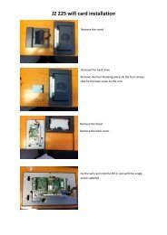
The HDDs can easily be accessed by removing a panel on the left side of the unit. HDDscan be installed or removed in seconds by removing one screw. A carrying tray fits ontoa drive without tools. The drive can now easily be slid in or out of the drive bay using thepull tab on the drive dray.HDD access panelHDD slide in-slide out drive bay<strong>Touch</strong> <strong>Screen</strong>The <strong>J2</strong> <strong>625</strong> can be ordered with two different touch screen technologies, PCT or TFR.The PCT unit uses a multi-touch Projected Capacitive Technology touch screen. The PCTtouch screen has no known failure mode-- it does not “wear out.” This screen istempered glass and does not reduce the brightness of the <strong>J2</strong> <strong>625</strong> panel. When operatingin a very high use environment, the PCT is the recommended touch screen technology.The PCT touch screen will work with most gloves and stylus that are designed to workwith tablet computers, and the screen has a smooth glass surface that is reflective.The TFR uses a five-wire true flat (zero bezel) resistive touch screen rated at 35 milliontouches per point. The resistive technology is very responsive and is the traditional choicefor a hospitality POS system. The screen has an anti-reflective plastic film surface.Both screens are fully spill proof, dust proof, and can be cleaned with a standard glasscleaner. The <strong>J2</strong> <strong>625</strong> touch screen was designed to easily be changed, normally in less thantwo minutes. Depending on operating environment and usage, both the Resistive andPCT touch screens have strengths and weaknesses; therefore <strong>J2</strong> offers both touch screentechnologies on the <strong>J2</strong> <strong>625</strong> unit, providing our customers with a choice for anyapplication requirement.<strong>J2</strong> <strong>625</strong> <strong>System</strong> <strong>Manual</strong>Version 0.1 June15, 2012 (Draft)11
<strong>System</strong> BoardPOS computers typically have a lifespan of 10 years or longer, therefore product qualityis of the utmost importance. <strong>J2</strong> <strong>625</strong> electronics are built with high-end components toensure reliability and long lasting product performance.The system board is designed for quick replacement, with just a few screws and cables tounplug. The board can be swapped out in less than three minutes.<strong>J2</strong> <strong>625</strong> <strong>System</strong> board<strong>J2</strong> <strong>625</strong> DisplayThe <strong>J2</strong> <strong>625</strong> offers 15 inch 1024 x 768 resolution display with 16.2 Million colors, CCFLbacklight with 4:3 aspect ratio screen. The brightness is rated at 250cd/m 2 . The Intelcontroller allows for the display to be rotated to 0, 90, 180 or 270 degrees without loss ofperformance. The driver can also scale the display resolution so that it can work properlywith applications written for 800x600 resolutions.The <strong>J2</strong> <strong>625</strong> electronics also supports dimming, and can be controlled directly byWindows 7 or 8, or with <strong>J2</strong> supplied utilities for Windows XP. Dimming levels between10-100% are supported. A hardware auto dimming feature is built-in to ensure the longestbacklight life and to also provide the lowest power usage.<strong>J2</strong> <strong>625</strong> <strong>System</strong> <strong>Manual</strong>Version 0.1 June15, 2012 (Draft)12
Secondary Video PortThe <strong>J2</strong> <strong>625</strong> supports the newer digital video standard Display Port connector. Thisconnector supports a Display Port monitor, HDMI display, DVI or VGA monitor. Whenused with HMDI or DVI displays, a passive adaptor cable must be used. When using aVGA display, an active adaptor is to be used. With HDMI display Audio, support isprovided via the same HMDI cable.The secondary video displays can be configured as Twin, Intel Dual Display Clone, orExtended Desktop. Most all monitor resolutions from 640 x 480, up to 2560 x 1600 aresupported.DisplayPort Video PortEthernet ConnectionThe <strong>J2</strong> <strong>625</strong> uses the Realtek RTL8111 Gigabit Ethernet controller. The Ethernetconnector is located in the cable well, as shown below. The Ethernet controller supportsWake on LAN, and the BIOS supports a PXE boot ROM as well. There is a LED on theLAN connector, this Green LED light turns on when there is LAN activity.Ethernet Connector<strong>J2</strong> <strong>625</strong> <strong>System</strong> <strong>Manual</strong>Version 0.1 June15, 2012 (Draft)13
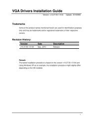
Serial portsThe <strong>J2</strong> <strong>625</strong> unit has four external RS232 serial ports, all of which can supply +12Vpower. The serial ports use a ten pin RJ45 connector. The unit comes standard with fourserial cables, three 25cm (10”) RJ45 to DB9 adapter cables, and one 152cm (5’) RJ45 toDB25 serial printer cable that works with EPSON and EPSON compatible printers.All serial (COM) ports can be BIOS-enabled to provide +12Vpower to external devices.This power is supplied via pin 10 of the RJ45 which corresponds to pin 9 on the DB9adaptor. The maximum current per port is 1 amp, with a total maximum external loadingon the +12V of 3 amps.A set of stick-on color coded labels are supplied with the cable adaptors, so that thecables can be marked. This makes it easy to plug the cable back into the correct port,should you need to service the unit.Serial PortsBIOS Setting Serial Port(s) Power Enable<strong>J2</strong> <strong>625</strong> <strong>System</strong> <strong>Manual</strong>Version 0.1 June15, 2012 (Draft)14
RJ45 to DB9 <strong>J2</strong> Adaptor Cable Pin-Out when using CAT5/6 CableRJ45-10 Pin DB9 Signal RJ45- 8 Pin DB9 SignalPin 1 --- --- --- --- ---Pin 2 Pin 1 DCD Pin 1 Pin 1 DCDPin 3 Pin 6 DSR Pin 2 Pin 6 DSRPin 4 Pin 2 RD Pin 3 Pin 2 RDPin 5 Pin 7 RTS Pin 4 Pin 7 RTSPin 6 Pin 3 SD Pin 5 Pin 3 SDPin 7 Pin 8 CTS Pin 6 Pin 8 CTSPin 8 Pin 4 DTR Pin 7 Pin 4 DTRPin 9 Pin 5 GND Pin 8 Pin 5 GNDPin 10 Pin 9 RI --- --- ---The <strong>J2</strong> Cable Adaptor (supplied)RJ45 to DB25 <strong>J2</strong> Serial Pinter Cable Pin-out when using 8 wire CAT5/6 cableRJ45-10 Pin Signal DB25 Signal RJ45- 8 Pin Signal DB25 SignalPin 1 --- --- --- --- --- --- ---Pin 2 DCD --- --- Pin 1 DCD --- ---Pin 3 DSR Pin 20 DTR Pin 2 DSR Pin 20 DTRPin 4 RD Pin 2 SD Pin 3 RD Pin 2 SDPin 5 RTS Pin 5 CTS Pin 4 RTS Pin 5 CTSPin 6 SD Pin 3 RD Pin 5 SD Pin 3 RDPin 7 CTS Pin 4 RTS Pin 6 CTS Pin 4 RTSPin 8 DTR Pin 6 DSR Pin 7 DTR Pin 6 DSRPin 9 GND Pin 7 GND Pin 8 GND Pin 7 GNDPin 10 --- --- --- --- --- --- ---Epson or Epson compatible serial printer cable<strong>J2</strong> <strong>625</strong> <strong>System</strong> <strong>Manual</strong>Version 0.1 June15, 2012 (Draft)15
USB PortsThe <strong>J2</strong> <strong>625</strong> has 6 external and 3 internal USB 2.0 ports. The 6 external ports (see below)are located in the cable well with one the side of the unit for easy access. The 3 internalports are used for different functions, such as using a PCT touch screen, Finger Printreader and/or other peripherals.USB PortsSide USB PortAudioThe <strong>J2</strong> <strong>625</strong> uses the VIA1708B HD audio controller. There is one internal speaker.A combo microphone jack and headset jack are located in the cable well of the <strong>J2</strong> <strong>625</strong>, asseen below, which allows for the connection of a microphone and headset, or audio out toother devices.Audio out is also supported on the DisplayPort when used with a HDMI monitor.Audio Jack Location<strong>J2</strong> <strong>625</strong> <strong>System</strong> <strong>Manual</strong>Version 0.1 June15, 2012 (Draft)16
Power SupplyThe <strong>J2</strong> <strong>625</strong> uses a notebook-type power supply that is mounted in the base of the unit.The power supply is rated with an output of 65 watts 18.5 VDC 3.5 Amps, and has aninput rating of 100-240VAC at 50~60Hz 1.7Amps maximum. The power supply has anefficiency rating V. The power supply connector is a standard notebook locking type thatplugs into the system power input connector, located in the cable well.Power Input connector+12VDV Power OutThe <strong>J2</strong> <strong>625</strong> has a fused power out connector that supplies a total of 12VDC, up to 2amp.The power supply connector is a standard notebook locking type that plugs into thesystem power input connector, located in the cable well, seen belowPower Output connectorCash Drawer PortsThe <strong>J2</strong> <strong>625</strong> is equipped with one Cash Drawer port that can support one or two drawers.This port is located in the cable well, and uses the industry standard RJ-11 connector andpin-out (illustrated below).Cash Drawer Ports<strong>J2</strong> <strong>625</strong> <strong>System</strong> <strong>Manual</strong>Version 0.1 June15, 2012 (Draft)17
Cash Drawer 1 Pin Assignment6 1PinSignal1 GND2 CD1 SOLENOID3 STATUS / STATUS CD14 24V5 CD2 SOLENOID6 GND / STATUS CD2The application may address the Cash Drawer port in two ways:1) Using the <strong>J2</strong>-supplied OPOS drivers for Windows.2) Direct access to the I/O portsCash Drawer Controller RegisterThe Cash Drawer Controller use one I/O address to control the Cash Drawer.Register Location: 48ChAttribute: Read / Write<strong>Size</strong>: 8bitBIT BIT7 BIT6 BIT5 BIT4 BIT3 BIT2 BIT1 BIT0Attribute Read Reserved Write Reserved7 6 5 4 3 2 1 0X X X XReservedCash Drawer 1 fireCash Drawer 2 fireReservedCash Drawer 1 statusCash Drawer 2 statusThe “Y” cable used to support two cash drawers on the one RJ-11 is the same as is usedon Epson printers.<strong>J2</strong> <strong>625</strong> <strong>System</strong> <strong>Manual</strong>Version 0.1 June15, 2012 (Draft)18
CMOS ClearThe <strong>J2</strong> <strong>625</strong> CMOS can be cleared by unplugging the system board CMOS battery for 30seconds before plugging it back in.CMOS BatteryMini PCI-EThe onboard Mini PCI Express connector is normally used for the optional internal802.11b/g/n wireless LAN card.Mounting Screw<strong>J2</strong> <strong>625</strong> <strong>System</strong> <strong>Manual</strong>Version 0.1 June15, 2012 (Draft)19
Memory SODIMM(s)The <strong>J2</strong> <strong>625</strong> supports two SODIMM DDR3 memory sockets. The unit comes standardwith 2GB of main memory and can support up to a maximum of 4GB. The memory typeis DDR3 800/1066.Typical Power Consumption <strong>J2</strong> <strong>625</strong>The typical power consumption of the <strong>J2</strong> <strong>625</strong> is lower than a notebook computer and morecomparable to a netbook computer. Using the latest generation Intel’s Atom processor andchipset allows for much lower power consumption than previous generations of POS computers.When coupled with the proper system configuration, this can greatly reduce the system totalcarbon foot print.Test conditionsVoltage:220VAC 50Hz, measured voltage 236 VACOS: POSReady 7Heavy Load Program: PassMark BurnInTest defaults valuesMaximum load: PassMark BurnInTest Max CPU TempTemperature: 26cAll systems are tested in their standard hard drive configuration. Results are +/- 15%.<strong>J2</strong> <strong>625</strong> D2550 1.86GHz1: Normal application including most POS software 23 watts2: Very heavy load application 26 watts3: Maximum load 29 watts4: Normal POS app, backlight dimmed 20 watts4: Normal POS app, backlight off 18 watts5: Standby, unit off, waiting for wake on LAN, RTC or power button >4 watts<strong>J2</strong> <strong>625</strong> <strong>System</strong> <strong>Manual</strong>Version 0.1 June15, 2012 (Draft)20
ServiceRemoving the Head from the BaseThe <strong>625</strong> is shipped with a counter top base which allows for the head to be adjusted from0-90°.To remove the integrated head from the base, fully loosen the thumbscrew located on theback of the unit under the hinge of the counter top base, as shown below. Then lift thehead as illustrated:Loosen Thumb ScrewSlide Head up to remove<strong>J2</strong> <strong>625</strong> <strong>System</strong> <strong>Manual</strong>Version 0.1 June15, 2012 (Draft)21
Removing the Power SupplyThe power supply is normally located in the counter top base. When using a wall mountbracket or the <strong>J2</strong> UPS, the power supply would be external from the unit.To remove the power supply from the base, two screws needs to be removed as shown.Screw locations<strong>J2</strong> <strong>625</strong> <strong>System</strong> <strong>Manual</strong>Version 0.1 June15, 2012 (Draft)22
VESA MountingThe <strong>625</strong> unit also supports the industry standard 100mm VESA mounting. The samemounting hard point used for the counter top base is used for VESA mounting. The fourpoint that thread holes for 4mm screws.100mm VESA PatternThreaded Mounting point(s), 4mm screw<strong>J2</strong> <strong>625</strong> <strong>System</strong> <strong>Manual</strong>Version 0.1 June15, 2012 (Draft)23
Removing the Back CoverThe following steps show how to disassemble the <strong>625</strong> for servicing:On a clean, protected surface, place the unit screen-side down. Remove the four coverscrews as shown. Carefully lift the back cover as shown.Remove four screws where shownCarefully tilt up the back cover to removeNote: The <strong>625</strong> was designed so that the internals of the unit could be accessed withouthaving to remove the mounting base or the mounting bracket of the unit.<strong>J2</strong> <strong>625</strong> <strong>System</strong> <strong>Manual</strong>Version 0.1 June15, 2012 (Draft)24
Changing the <strong>System</strong> Board*Special Note: An anti-static workplace with proper grounding is required whenchanging the <strong>System</strong> Board.First remove the back cover. Then remove the 3 screws hold the drive cage in place andremove it. Then remove the 5 screw hold the system board in place. Unplug all cablesgoing to the system board. Remove board. (see photo below)Three screws to remove <strong>System</strong> Board<strong>J2</strong> <strong>625</strong> <strong>System</strong> <strong>Manual</strong>Version 0.1 June15, 2012 (Draft)25
Adding MemoryNote: An anti-static workplace with proper grounding is required when addingmemory. Remove the back cover. You can now access the two memory sockets. The topmemory socket must be populated. The memory SODIMM can be installed or removedwithout removing the HDD cage.The <strong>J2</strong> <strong>625</strong> supports up to 4GB of memory in two sockets. The unit comes standard with2GB of main memory and can support up to a maximum of 4GB. The memory type isDDR3 800/1066.Memory sockets<strong>J2</strong> <strong>625</strong> <strong>System</strong> <strong>Manual</strong>Version 0.1 June15, 2012 (Draft)26
BIOS SettingMain <strong>Screen</strong>The main BIOS allows for the display of system information, keyboard boot options, andthe setting of the time and date. The time and date may also be set via the operatingsystem.<strong>System</strong> InformationThe <strong>J2</strong> <strong>625</strong> BIOS has a system information screen that displays useful systeminformation, including the serial number of the unit. This information may also beaccesed via DMI utilities.Note: This version of the new Phoenix BIOS does not have a screen shot utility yet. Please excuse the poor quality of the screenpictures. These will be replaced once the screen shot utility is available.<strong>J2</strong> <strong>625</strong> <strong>System</strong> <strong>Manual</strong>Version 0.1 June15, 2012 (Draft)27
Advanced <strong>Screen</strong>The Advance <strong>Screen</strong> allows for a number of BIOS options to be accessed. Please use carein changing these options, as some settings can cause the system to malfunction. Theseoptions are provided to offer maximum flexibility in configuring the <strong>J2</strong> <strong>625</strong>. The ItemSpecific Help (seen on the right hand side of the screen) explains each option.Boot Configuration<strong>J2</strong> <strong>625</strong> <strong>System</strong> <strong>Manual</strong>Version 0.1 June15, 2012 (Draft)28
Power ConfigurationThe power configuration option allows for changing the behavior of the unit when it ispowered up; it also enables changing the auto power-up feature.COM Power and LCD Brightness ConfigurationThis BIOS screen allows the enabling of the power for the serial ports, and changing thedefault brightness setting for the LCD screen. The LCD screen brightness can also be setvia the Windows OS.<strong>J2</strong> <strong>625</strong> <strong>System</strong> <strong>Manual</strong>Version 0.1 June15, 2012 (Draft)29
Security <strong>Screen</strong>The Security <strong>Screen</strong> is used to set BIOS accessed passwords.Boot <strong>Screen</strong>The boot priority order can be set with the Boot <strong>Screen</strong>.Keys are used to view or configure devices:Use up and down arrows to select a device.A plus and minus moves the device up or down in the list.A shift plus the number 1 enables or disables the device.A “!” will be displayed when a device is disabled in the boot list.<strong>J2</strong> <strong>625</strong> <strong>System</strong> <strong>Manual</strong>Version 0.1 June15, 2012 (Draft)30
Exit <strong>Screen</strong>The exit screen allows for the saving, discarding or loading of the default BIOS settings.These functions can also be performed any time using the F9 and F10 key.Phoenix Secure Core Tiano BIOSThe <strong>J2</strong> <strong>625</strong> uses the new Phoenix Secure Core Tiano BIOS. More information about thisnew UEFI BIOS came be found at the following web link.http://www.phoenix.com/pages/phoenix-securecore-tiano-tmDevice DriversAll device drivers for the <strong>J2</strong> <strong>625</strong> can be downloaded from the <strong>J2</strong> web site at:http://support.j2rs.com/<strong>625</strong>/Installation instructions are included with each driver.OPOS Drivers<strong>J2</strong> supports OPOS drivers for the following <strong>J2</strong> <strong>625</strong> peripherals:1: Cash Drawer(s)2: LCM 2X20 character customer display3: MSR ReaderThe driver and documentation can be downloaded from:http://support.j2rs.com/Utilities/OPOS/<strong>J2</strong> <strong>625</strong> <strong>System</strong> <strong>Manual</strong>Version 0.1 June15, 2012 (Draft)31
<strong>J2</strong> <strong>625</strong> Configuration UtilityThe <strong>J2</strong> <strong>625</strong> incorporates a microcontroller (MCU) that supports a number of systemfunctions. These include auto LCD backlight dimming, power LED control, power-ontimer, and power cycle counter. The <strong>J2</strong> <strong>625</strong> Configuration Utility allows for theconfiguration of options and for reading the current values of these various functions.InstallationThe utility can be downloaded from the <strong>J2</strong> web site: http://support.j2rs.com/<strong>625</strong>/utilities/To install, simply unzip anywhere and run setup. Like other <strong>J2</strong> utilities it can beuninstalled though the Windows control panel.MainThe main screen displays the following: the current version of firmware, the power oncount (in hours), a list of the number of power cycles, and the dim timeout setting anddim brightness settings. ( shown below):.<strong>J2</strong> <strong>625</strong> <strong>System</strong> <strong>Manual</strong>Version 0.1 June15, 2012 (Draft)32
Power-On HoursThe MCU uses an internal timer to keep track of how many total hours the <strong>J2</strong> <strong>625</strong> hasbeen up and running in its lifetime. This number shows powered-up hours only, not thepowered but off/standby time. The accuracy of this timer is only about +/- 5% and is tobe used as an approximate number. The value is stored in the MCU internal EEPROM.Power CyclesThe MCU tracks the total number of times the unit has been powered off and on in thepower cycle counter. The count is stored in the MCU EEPROM and is used fordiagnostic purposes. The power-on and power cycles can only be changed at the factory.Dim TimeoutThis value is the amount of time the MCU waits if there is no touch activity beforedimming the screen. This same function is built into Windows 7 and Windows 8 drivers,and should be used rather than the <strong>J2</strong> <strong>625</strong> hardware dimming. But for older operatingsystems (such as XP) the <strong>J2</strong> <strong>625</strong> hardware dimming default should be used.The default value for the hardware dim timeout is six minutes, but can be changed withthis utility from any value from 0-255 minutes.Note: a value of zero will disable the hardware auto dimming function.Once the dim timeout is reached the LCD screen will dim to the value set in DimBrightness. Any touch of the screen, such as MSR read, iButton read or keyboard activitythat changes the keyboard LED status will take the <strong>J2</strong> <strong>625</strong> out of auto dim mode. This isall done via hardware, and no software drivers need to be loaded. If it is required, the <strong>J2</strong>Dim Wake driver should be loaded if other activity is required to take the <strong>J2</strong> <strong>625</strong> out ofauto dim. This driver is described in the Dim Wake section of this manual.<strong>J2</strong> <strong>625</strong> <strong>System</strong> <strong>Manual</strong>Version 0.1 June15, 2012 (Draft)33
Dim BrightnessThe brightness level that the screen dims to when auto dim is active is controlled by theDim Brightness setting. This utility is used to change this value whose default value is10%. The possible range is from 5-95%, in 5% increments.Note: Dimming is important for a few reasons: one is to lower the total powerconsumption of the unit; another would be to prolong the LCD screen backlight LED life.<strong>J2</strong> <strong>625</strong> <strong>System</strong> <strong>Manual</strong>Version 0.1 June15, 2012 (Draft)34
Update MCU FirmwareThis tab is used to update the MCU firmware when necessary. This may be to add a newfeature or function to the MSR/iButton. <strong>J2</strong> will supply a firmware file for this whenrequired.Use the “Select Flash Firmware File” button to start the update, as shown below. Thiswill let you browse for the correct file.<strong>J2</strong> <strong>625</strong> <strong>System</strong> <strong>Manual</strong>Version 0.1 June15, 2012 (Draft)35
Once the hex file has been selected, touch the “Program Flash Firmware” button to startfirmware update. The utility will now update the MCU firmware. It will first write thememory then verify it. Do not turn off the <strong>J2</strong> <strong>625</strong> power when updating.MCU OptionThis tab is only used for factory programming and verification of the MCU option fuses.It will display the current value of the MCU option fuse (note that end-users normallywould not use this feature).<strong>J2</strong> <strong>625</strong> <strong>System</strong> <strong>Manual</strong>Version 0.1 June15, 2012 (Draft)36
DimWakeDimWake is a very small and simple utility that loads on any Windows OS, but normallyis only used with variations of the XP operating system (like XP Pro, POSReady 2009,WEPOS, or XP Embedded). The DimWake program is used to take the <strong>J2</strong> <strong>625</strong> out ofauto dim mode. The hardware can only take the system out of dimming by either a touchof the touch screen, MSR read, iButton read, or keyboard activity that changes thekeyboard LED status. Sometimes it is desirable for other events to take the system out ofdim mode, like a mouse movement. The DimWake program provides this function.InstallationThe utility can be downloaded from the <strong>J2</strong> web site: http://support.j2rs.com/<strong>625</strong>/utilities/To install just unzip anywhere and run setup. Like other <strong>J2</strong> utilities it can be uninstalledthrough the Windows control panel.Once having installed DimWake, you will need to reboot the system for it to take effect.DimWake will then be running in the background.Once installed and running - any mouse, keyboard or high CPU activity (like playing avideo) will bring hardware auto dimming out of dimming mode, or prevent it from goingin to dimming. This combination of hardware auto dimming and DimWake provides thatsame function to XP, as comes standard with Windows 7 and Windows 8. When usingWindows 7 or 8 it is best to use the built-in dimming feature.<strong>J2</strong> <strong>625</strong> <strong>System</strong> <strong>Manual</strong>Version 0.1 June15, 2012 (Draft)37
<strong>J2</strong> Health<strong>J2</strong> has a standard program that works with all its POS products, called <strong>J2</strong> Health. Thisprogram is used in either a standalone mode or in conjunction with <strong>J2</strong> remotemonitor/asset tracking software. The <strong>J2</strong> Health program monitors different aspects of thePOS hardware to ensure the hardware is running within specification. For the <strong>J2</strong> <strong>625</strong> itmonitors critical system voltages, as well as system and CPU temperatures.InstallationThe utility can be downloaded from the <strong>J2</strong> web site:http://support.j2rs.com/Utilities/Health/ To install just unzip anywhere and run setup.Like other <strong>J2</strong> utilities it can be uninstalled through the Windows control panel.Tray IconOnce installed and the system has rebooted, <strong>J2</strong> Health will be running in the background.The <strong>J2</strong> health icon will appear in the task bar tray:Right-clicking on this icon displays different Health options, shown below:The current health values will display by clicking on “Display Health Values”.A sample screen is shown below:<strong>J2</strong> <strong>625</strong> <strong>System</strong> <strong>Manual</strong>Version 0.1 June15, 2012 (Draft)38
As can be seen above, when running on the <strong>J2</strong> <strong>625</strong> the <strong>J2</strong> Health program displays criticalsystem voltages and system and CPU Core temperatures. For other <strong>J2</strong> POS systems, <strong>J2</strong>Health may display more or less information. An example would be the <strong>J2</strong> <strong>625</strong> unit,which in addition to the above information would also display the fan speed of the two <strong>J2</strong><strong>625</strong> fans.Logging to FileThe <strong>J2</strong> Health program can log the health data to a file in the csv text format forimporting to other programs, like Excel. This can be handy for finding “time of day”related problems.When logging is enabled, the tray icon Rx symbol will change to red to indicate loggingin is taking place.<strong>J2</strong> <strong>625</strong> <strong>System</strong> <strong>Manual</strong>Version 0.1 June15, 2012 (Draft)39
Registry EntriesThe <strong>J2</strong> Health program creates registry entries for the different health values. Dynamicvalues are updated at the user defined interval, which is by default 5 seconds. Othersoftware may use these registry entries to access the <strong>J2</strong> health information.<strong>J2</strong> <strong>625</strong> Health keys are shown below:<strong>J2</strong> Remote Monitoring Software<strong>J2</strong> now offers a full remote monitoring and asset tracking solution that works inconjunction with <strong>J2</strong> Health to ensure the highest uptime possible of your POS hardware.Please contact <strong>J2</strong> sales for more information on this fully customizable, remotemonitoroption.For more information, please visit us athttp://www.j2retailsystems.com/newsarticle.php?news_id=57<strong>J2</strong> <strong>625</strong> <strong>System</strong> <strong>Manual</strong>Version 0.1 June15, 2012 (Draft)40
SMI BIOS Info UtilityThe <strong>J2</strong> SMI BIOS Info program allows for the reading of all populated BIOS DMI/SMIinformation. With some <strong>J2</strong> products including the <strong>J2</strong> <strong>625</strong>, this information also includesdynamic system health information. Normally this dynamic DMI health informationBIOS is only supported on very high end servers. Now <strong>J2</strong> brings this feature to POShardware.The <strong>J2</strong> SMI BIOS Info program will run on any <strong>J2</strong> POS hardware or for that fact on anyPC hardware. It can display all DMI/SMI information on a formatted form.InstallationThe utility can be downloaded from the <strong>J2</strong> web site: http://support.j2rs.com/Utilities/To install just unzip anywhere and run as you wish to run the utility form.OperationsJust click on the .exe file to run. The following screen will be displayed (see below).Note that the health data will only display on newer <strong>J2</strong> systems that support the dynamicDMI health BIOS.<strong>J2</strong> <strong>625</strong> <strong>System</strong> <strong>Manual</strong>Version 0.1 June15, 2012 (Draft)41
Cash Drawer Test Utility<strong>J2</strong> has a generic cash drawer test utility that works on all <strong>J2</strong> products, including the new<strong>J2</strong> <strong>625</strong> computer. This test program also supports the <strong>J2</strong> <strong>625</strong> separate status lines, such aswhen the special <strong>J2</strong> <strong>625</strong> “Y” cable is used, supporting two cash drawers.InstallationThe utility can be downloaded from the <strong>J2</strong> web site: http://support.j2rs.com/Utilities/To install just unzip anywhere and run as you wish to download the utility form.OperationJust run the cash drawer test from whatever folder it was installed into. Use the “UseDirect I/O Port 48c” setting to test the cash drawer(s). (See example below)<strong>J2</strong> <strong>625</strong> <strong>System</strong> <strong>Manual</strong>Version 0.1 June15, 2012 (Draft)42
To use two cash drawers with the <strong>J2</strong> <strong>625</strong> you use a “Y” cable, either the <strong>J2</strong> standard “Y”cable that also works with Epson printers or the special <strong>J2</strong> <strong>625</strong> “Y” cable that supportsseparate status lines (The standard cable supports shared status lines.). When using thespecial cable check the “Use Separate Status for Drawer2” box. The test screen will nowlook like this:The “Use Comm Port 10 & 11” option is to test the cash drawer you set up using the <strong>J2</strong>virtual serial ports program. The virtual serial port program must be installed with thecash drawer virtual serial ports set to Comm 10 & 11.<strong>J2</strong> <strong>625</strong> <strong>System</strong> <strong>Manual</strong>Version 0.1 June15, 2012 (Draft)43
<strong>J2</strong> Virtual Serial Ports DriversVirtual serial ports can be used for the cash drawers, virtual 2x20 line display on theoptional 10.1 LCD, Smart UPS, MSR and iButton.To open virtual serial cash drawer send a bell character to the Com port it is assigned to.(The bell character is the ASCII 07 hex character “Control G.”) The open/close status ofthe drawer may be obtained by reading the status bits of its COM port. The draweropen/close status will be reflected on the CTS and RI bits, either bit may be used. Thisvirtual COM port driver is designed to work the same as a hardware serial cash drawerand will work with drivers for serial cash drawers.<strong>J2</strong> <strong>625</strong> <strong>System</strong> <strong>Manual</strong>Version 0.1 June15, 2012 (Draft)44
<strong>J2</strong> <strong>625</strong> OptionsMSROverviewThe <strong>625</strong> can be ordered with a 3 track MSR. This MSR is the same as used on the <strong>J2</strong>580/615/630/680 POS systems. The MSR mounts on the right side of the <strong>625</strong> and uses afront facing MSR slot. This allows the <strong>625</strong> unit to be placed side by side, or in tightspaces, and still be able to swipe the card. The MSR appears to the software as a wedgetype MSR with all data from the MSR being sent to the keyboard port. The MSRconfiguration utility can be down loaded from <strong>J2</strong> web site.<strong>625</strong> with front swipe MSR<strong>J2</strong> <strong>625</strong> <strong>System</strong> <strong>Manual</strong>Version 0.1 June15, 2012 (Draft)45
Installing the <strong>625</strong> MSRThe <strong>625</strong> MSR is installed by first removing the two rubber plugs for the optionattachment point as shown below.Remove Rubber plugsThen remove the MSR cover plate on the right back side of the unit by removing the twoscrews, as shown.Remove MSR cover plate<strong>J2</strong> <strong>625</strong> <strong>System</strong> <strong>Manual</strong>Version 0.1 June15, 2012 (Draft)46
Connect the cable together as shown add secure the static ground wire with screwprovided as shown.Attach cablesAttach the MSR using the two screws at the locations shown below.Mounting MSRYou may now power up the <strong>625</strong> and the MSR should be working. For a quick test youcan open Notepad and swipe a card, the information should appear in Notepad. You cannow run the <strong>J2</strong> MSR utility if you need any custom settings for the MSR.<strong>J2</strong> <strong>625</strong> <strong>System</strong> <strong>Manual</strong>Version 0.1 June15, 2012 (Draft)47
Customer DisplayOverviewA 2 line by 20 character VFD or LCM customer side display is available optional for the<strong>J2</strong> <strong>625</strong>. This customer display is the same as used on the <strong>J2</strong> 580/615/630/680 POSsystems.VFD 2x20 Customer DisplayLCD 2x20 Customer Display<strong>J2</strong> <strong>625</strong> <strong>System</strong> <strong>Manual</strong>Version 0.1 June15, 2012 (Draft)48
Secondary Video DisplayThe <strong>J2</strong> <strong>625</strong> has the same options as available on the <strong>J2</strong> 580/615/630/680 POS systems.Secondary display of 10 inch, 12 inch 4:3 and 10.1 inch 16:9 displays are available.10 inch 4:3 Display10.1 inch 16:9 1024x600 Display<strong>J2</strong> <strong>625</strong> <strong>System</strong> <strong>Manual</strong>Version 0.1 June15, 2012 (Draft)49
Optional Wall Mount BracketThis option is the same as available on the <strong>J2</strong> 580/615/630/680 POS systems. The wallmount bracket has threaded mounting holes (screws provided) for the 75mm VESAstandard; and unthreaded holes for the 100mm standard.Using the 100mm hole pattern the bracket can be used by itself as a wall mount bracket.After installing the thumbscrew clip mount bracket to the wall, hang the <strong>J2</strong> <strong>625</strong> on thebracket.Install screw to secure thumbscrew clipThe bracket slides on to the <strong>J2</strong> <strong>625</strong> mount posts, as shown. Normally the bracket wouldalready be mounted to the wall or a VESA mount and the <strong>625</strong> would be hung on thebracket. Once in place the thumb screw would be tightened.<strong>J2</strong> <strong>625</strong> <strong>System</strong> <strong>Manual</strong>Version 0.1 June15, 2012 (Draft)50
Fingerprint Reader / MSRThis option is the same as available on the <strong>J2</strong> 580/615/630/680 POS systems. This readeruses the Digital Personal module.iButton / MSRThis option is the same as available on the <strong>J2</strong> 580/615/630/680 POS systems.<strong>625</strong> UPSAvailable Q3 2012RFIDAvailable Q3 2012Pole Mount OptionsThe <strong>J2</strong> <strong>625</strong> has the same options as available on the <strong>J2</strong> 580/615/630/680 POS systems.<strong>J2</strong> <strong>625</strong> <strong>System</strong> <strong>Manual</strong>Version 0.1 June15, 2012 (Draft)51
Contact InformationEuropean Office<strong>J2</strong> Retail <strong>System</strong>s Ltd.<strong>J2</strong> HouseClayton Road, BirchwoodWarrington WA3 6RPUnited Kingdom44 (0) 1925 817003 Phone44 (0) 1925 811989 FaxUSA Office<strong>J2</strong> Retail <strong>System</strong>s Inc.9251 Irvine BoulevardIrvine, CA 92618USA(714) 669-3111 Phone(714) 669-3133 FaxAustralian Office<strong>J2</strong> Retail <strong>System</strong>s Pty LtdUnit 6 83/85 Boundary RoadMortdale NSW 2223Australia02 9584 5222 Phone02 9584 1500 FaxWebsitehttp://www.j2retailsystems.com<strong>J2</strong> <strong>625</strong> <strong>System</strong> <strong>Manual</strong>Version 0.1 June15, 2012 (Draft)52