Procedural Lab Template, Student Version, Required Components
Procedural Lab Template, Student Version, Required Components
Procedural Lab Template, Student Version, Required Components
- No tags were found...

You also want an ePaper? Increase the reach of your titles
YUMPU automatically turns print PDFs into web optimized ePapers that Google loves.
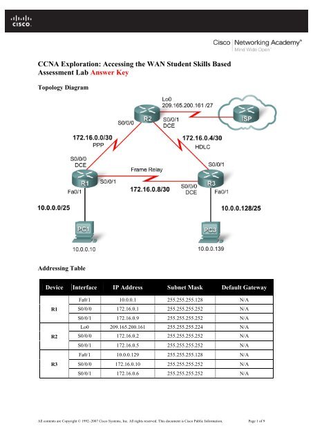
CCNA Exploration: Accessing the WAN <strong>Student</strong> Skills BasedAssessment <strong>Lab</strong> Answer KeyTopology DiagramAddressing TableDevice Interface IP Address Subnet Mask Default GatewayR1R2R3Fa0/1 10.0.0.1 255.255.255.128 N/AS0/0/0 172.16.0.1 255.255.255.252 N/AS0/0/1 172.16.0.9 255.255.255.252 N/ALo0 209.165.200.161 255.255.255.224 N/AS0/0/0 172.16.0.2 255.255.255.252 N/AS0/0/1 172.16.0.5 255.255.255.252 N/AFa0/1 10.0.0.129 255.255.255.128 N/AS0/0/0 172.16.0.10 255.255.255.252 N/AS0/0/1 172.16.0.6 255.255.255.252 N/AAll contents are Copyright © 1992–2007 Cisco Systems, Inc. All rights reserved. This document is Cisco Public Information. Page 1 of 9
CCNA ExplorationAccessing the WAN: Skills Based Assessment<strong>Student</strong> Skills based Assessment <strong>Lab</strong>Device Interface IP Address Subnet Mask Default GatewayPC1 NIC 10.0.0.10 255.255.255.128 10.0.0.1PC3 NIC 10.0.0.139 255.255.255.128 10.0.0.129Learning ObjectivesTo complete this lab:• Cable a network according to the topology diagram• Erase the startup configuration and reload a router to the default state• Perform basic configuration tasks on a router• Configure and activate interfaces• Configure and activate serial interfaces (PPP with CHAP, HDLC, and Frame Relay)• Configure RIP on all the routers• Configure basic router security• Configure ACLs• Configure basic NATScenarioThis lab tests you on the skills and knowledge that you learned in Exploration 4. Use cisco for all passwords inthis lab, except for the enable secret password, which is class.Task 1: Prepare the NetworkStep 1: Cable a network that is similar to the one in the topology diagram.Step 2: Clear any existing configurations on the routers.Task 2: Perform Basic Device ConfigurationsConfigure the R1, R2, and R3 routers according to the following guidelines:R1:• Configure the router hostname.• Disable DNS lookup.• Configure an EXEC mode password.• Configure a message-of-the-day banner.• Configure a password for console connections.• Configure synchronous logging.• Configure a password for vty connections.Router>enableRouter#configure terminalRouter(config)#hostname R1R1(config)#banner motd #R1#R1(config)#no ip domain-lookupR1(config)#enable secret classAll contents are Copyright © 1992–2007 Cisco Systems, Inc. All rights reserved. This document is Cisco Public Information. Page 2 of 9
CCNA ExplorationAccessing the WAN: Skills Based Assessment<strong>Student</strong> Skills based Assessment <strong>Lab</strong>R1(config)#line console 0R1(config-line)#password ciscoR1(config-line)#loginR1(config-line)#logging synchronousR1(config-line)#exec-timeout 5R1(config-line)#exitR1(config)#line vty 0 4R1(config-line)#password ciscoR1(config-line)#loginR1(config-line)#logging synchronousR1(config-line)#exec-timeout 5R1(config-line)#exitR2:Router>enableRouter#configure terminalRouter(config)#hostname R2R2(config)#banner motd #R2#R2(config)#no ip domain-lookupR2(config)#enable secret classR2(config)#line console 0R2(config-line)#password ciscoR2(config-line)#loginR2(config-line)#logging synchronousR2(config-line)#exec-timeout 5R2(config-line)#exitR2(config)#line vty 0 4R2(config-line)#password ciscoR2(config-line)#loginR2(config-line)#logging synchronousR2(config-line)#exec-timeout 5R2(config-line)#exitR3:Router>enableRouter#configure terminalRouter(config)#hostname R3R3(config)#banner motd #R3#R3(config)#no ip domain-lookupR3(config)#enable secret classR3(config)#line console 0R3(config-line)#password ciscoR3(config-line)#loginR3(config-line)#logging synchronousR3(config-line)#exec-timeout 5R3(config-line)#exitAll contents are Copyright © 1992–2007 Cisco Systems, Inc. All rights reserved. This document is Cisco Public Information. Page 3 of 9
CCNA ExplorationAccessing the WAN: Skills Based Assessment<strong>Student</strong> Skills based Assessment <strong>Lab</strong>R3(config)#line vty 0 4R3(config-line)#password ciscoR3(config-line)#loginR3(config-line)#logging synchronousR3(config-line)#exec-timeout 5R3(config-line)#exitTask 3: Configure and Activate Serial and Ethernet AddressesStep 1: Configure interfaces on R1, R2, and R3.Step 2: Verify IP addressing and interfaces.Step 3: Configure the PC1 and PC3 Ethernet interfaces.Step 4: Test connectivity between the PCs and routers.R1:R1(config)#interface fastEthernet0/1R1(config-if)#ip address 10.0.0.1 255.255.255.128R1(config-if)#no shutdownR1(config-if)#exitR1(config)#interface Serial0/0/0R1(config-if)#ip address 172.16.0.1 255.255.255.252R1(config-if)#clock rate 64000R1(config-if)#no shutdownR1(config-if)#exitR1(config)#interface Serial0/0/1R1(config-if)#ip address 172.16.0.9 255.255.255.252R1(config-if)#no shutdownR1(config-if)#endR1#show ip interface briefR2:R2(config)#interface Serial0/0/0R2(config-if)#ip address 172.16.0.2 255.255.255.252R2(config-if)#no shutdownR2(config-if)#exitR2(config)#interface Serial0/0/1R2(config-if)#ip address 172.16.0.5 255.255.255.252R1(config-if)#clock rate 64000R2(config-if)#no shutdownR2(config-if)#exitR2(config)#interface Loopback0R2(config-if)#ip address 209.165.200.161 255.255.255.224R2(config-if)#no shutdownR2(config-if)#endR2#show ip interface briefAll contents are Copyright © 1992–2007 Cisco Systems, Inc. All rights reserved. This document is Cisco Public Information. Page 4 of 9
CCNA ExplorationAccessing the WAN: Skills Based Assessment<strong>Student</strong> Skills based Assessment <strong>Lab</strong>R3:R3(config)#interface fastEthernet0/1R3(config-if)#ip address 10.0.0.129 255.255.255.128R3(config-if)#no shutdownR3(config-if)#exitR3(config)#interface Serial0/0/0R3(config-if)#ip address 172.16.0.10 255.255.255.252R3(config-if)#clock rate 64000R3(config-if)#no shutdownR3(config-if)#exitR3(config)#interface Serial0/0/1R3(config-if)#ip address 172.16.0.6 255.255.255.252R3(config-if)#no shutdownR3(config-if)#endR3#show ip interface briefTask 4: Configure Serial InterfacesStep 1: Configure and verify PPP encapsulation with CHAP authentication between R1 and R2. Thepassword is “cisco”.Step 2: Configure and verify HDLC encapsulation between R2 and R3.Step 3: Configure Frame Relay between R1 and R3.R1:R1#configure terminalR1(config)#username R2 password ciscoR1(config)#interface Serial0/0/0R1(config-if)#encapsulation pppR1(config-if)#ppp authentication chapR1(config-if)#exitR1(config)#interface Serial0/0/1R1(config-if)#encapsulation frame-relayR1(config-if)#frame-relay map ip 172.16.0.9 101 broadcastR1(config-if)#frame-relay map ip 172.16.0.10 101 broadcastR1(config-if)#frame-relay interface-dlci 101R1(config-if)#no keepaliveR1(config-if)#endR1#show interface Serial0/0/0R1#show interface Serial0/0/1R3#show frame-relay pvcR3#show frame-relay mapR2:R2#configure terminalR2(config)#username R1 password ciscoR2(config)#interface Serial0/0/0R2(config-if)#encapsulation pppAll contents are Copyright © 1992–2007 Cisco Systems, Inc. All rights reserved. This document is Cisco Public Information. Page 5 of 9
CCNA ExplorationAccessing the WAN: Skills Based Assessment<strong>Student</strong> Skills based Assessment <strong>Lab</strong>R2(config-if)#ppp authentication chapR2(config-if)#exitR2(config)#interface Serial0/0/1R2(config-if)#encapsulation hdlcR2(config-if)#endR2#show interface Serial0/0/0R2#show interface Serial0/0/1R3:R3#configure terminalR3(config)#interface Serial0/0/0R3(config-if)#encapsulation frame-relayR3(config-if)#frame-relay map ip 172.16.0.10 101 broadcastR3(config-if)#frame-relay map ip 172.16.0.9 101 broadcastR3(config-if)#frame-relay interface-dlci 101R3(config-if)#no keepaliveR3(config-if)#exitR3(config)#interface Serial0/0/1R3(config-if)#encapsulation hdlcR3(config-if)#endR3#show interface Serial0/0/0R3#show interface Serial0/0/1R3#show frame-relay pvcR3#show frame-relay mapTask 5: Configure RIPStep 1: Configure RIP on R1, R2, and R3.RIP updates should only be sent on the serial links between the routers. Prevent all other RIP updates onall networks.Step 2: Test connectivity with the ping command.Step 3: Verify the routing table with the appropriate command.R1:R1#configure terminalR1(config)#router ripR1(config-router)#version 2R1(config-router)#network 10.0.0.0R1(config-router)#network 172.16.0.0R1(config-router)#passive-interface fastEthernet0/1R1(config-router)#no auto-summaryR1(config-router)#endR1#show ip protocolsR1#show ip routeAll contents are Copyright © 1992–2007 Cisco Systems, Inc. All rights reserved. This document is Cisco Public Information. Page 6 of 9
CCNA ExplorationAccessing the WAN: Skills Based Assessment<strong>Student</strong> Skills based Assessment <strong>Lab</strong>R2:R2#configure terminalR2(config)#ip route 0.0.0.0 0.0.0.0 Loopback0R2(config)#router ripR2(config-router)#version 2R2(config-router)#network 172.16.0.0R2(config-router)#no auto-summaryR2(config-router)#redistribute staticR2(config-router)#endR2#show ip protocolsR2#show ip routeR3:R3#configure terminalR3(config)#router ripR1(config-router)#version 2R3(config-router)#network 10.0.0.0R3(config-router)#network 172.16.0.0R3(config-router)#passive-interface fastEthernet0/1R3(config-router)#no auto-summaryR3(config-router)#endR3#show ip protocolsR3#show ip routeTask 6: Configure Basic Router SecurityStep 1: Enable a secure Telnet login using a local database on R2.Step 2: Disable unused services and interfaces on R2.Step 3: Confirm that R2 is secured.R2:R2#configure terminalR2(config)#username cisco password ciscoR2(config)#aaa new-modelR2(config)#aaa authentication login LOCAL_AUTH localR2(config)#line vty 0 4R2(config-line)#login authentication LOCAL_AUTHR2(config)#no service padR2(config)#no service fingerR2(config)#no service udp-small-serverR2(config)#no service tcp-small-serverR2(config)#no ip bootp serverR2(config)#no ip http serverR2(config)#no ip fingerR2(config)#no ip source-routeR2(config)#no ip gratuitous-arpsAll contents are Copyright © 1992–2007 Cisco Systems, Inc. All rights reserved. This document is Cisco Public Information. Page 7 of 9
CCNA ExplorationAccessing the WAN: Skills Based Assessment<strong>Student</strong> Skills based Assessment <strong>Lab</strong>R2(config)#no cdp runTask 7: Configure Access Control ListsStep 1: Allow telnet to R1 and R3 from R2 only.Step 2: Do not allow HTTP, Telnet, and FTP traffic from the Internet to PC1.Step 3: Do not allow PC1 to receive traffic from the 10.0.0.128 /25 network.Step 4: Verify that PC3 cannot ping PC1, but can ping 10.0.0.1.R1:R1#configure terminalR1(config)#access-list 101 permit tcp host 172.16.0.2 any eq 23R1(config)#access-list 101 permit tcp host 172.16.0.5 any eq 23R1(config)#access-list 101 deny tcp any any eq 23R1(config)#access-list 101 permit ip any anyR1(config)#line vty 0 4R1(config-line)#access-class 101 inR1(config-line)#endR1#show ip access-listsR2:R2#configure terminalR2(config)#access-list 102 deny tcp any host 10.0.0.10 eq 80R2(config)#access-list 102 deny tcp any host 10.0.0.10 eq 23R2(config)#access-list 102 deny tcp any host 10.0.0.10 eq 21R2(config)#access-list 102 deny tcp any host 10.0.0.10 eq 20R2(config)#access-list 102 permit ip any anyR2(config)#interface Loopback0R2(config-if)#ip access-group 102 inR2(config-if)#endR2#show ip access-listsR3:R3#configure terminalR3(config)#access-list 101 permit tcp host 172.16.0.2 any eq 23R3(config)#access-list 101 permit tcp host 172.16.0.5 any eq 23R3(config)#access-list 101 deny tcp any any eq 23R3(config)#access-list 101 permit ip any anyR3(config)#line vty 0 4R3(config-line)#access-class 101 inR3(config-line)#endR3(config)#access-list 103 deny ip 10.0.0.128 0.0.0.127 host 10.0.0.10R3(config)#access-list 103 permit ip any anyAll contents are Copyright © 1992–2007 Cisco Systems, Inc. All rights reserved. This document is Cisco Public Information. Page 8 of 9
CCNA ExplorationAccessing the WAN: Skills Based Assessment<strong>Student</strong> Skills based Assessment <strong>Lab</strong>R3(config)#interface Serial0/0/0R3(config-if)#ip access-group 103 outR3(config-if)#exitR3(config)#interface Serial0/0/1R3(config-if)#ip access-group 103 outR3(config-if)#endR3#show ip access-listsTask 8: Configure NAT.Step 1: Configure NAT to allow PC3 to ping PC1.Step 2: Verify that PC3 can reach PC1.R3:R3#configure terminalR3(config)#access-list 104 permit ip 10.0.0.128 0.0.0.127 anyR3(config)#ip nat inside source list 104 interface Serial0/0/0 overloadR3(config)#interface fastEthernet0/1R3(config-if)#ip access-group 104 inR3(config-if)#ip nat insideR3(config-if)#exitR3(config)#interface Serial0/0/0R3(config-if)#ip nat outsideR3(config-if)#exitR3(config)#interface Serial0/0/1R3(config-if)#ip nat outsideR3(config-if)#endR3#show ip access-listsTask 9: Document the Router ConfigurationsTask 10: Clean UpErase the configurations and reload the routers. Disconnect and store the cabling. For PC hosts that are normallyconnected to other networks, such as the school LAN or to the Internet, reconnect the appropriate cabling andrestore the TCP/IP settings.All contents are Copyright © 1992–2007 Cisco Systems, Inc. All rights reserved. This document is Cisco Public Information. Page 9 of 9