
Create successful ePaper yourself
Turn your PDF publications into a flip-book with our unique Google optimized e-Paper software.
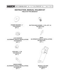
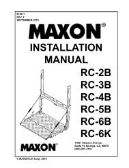
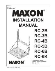
M-00-24REV. JOCTOBER 2010Installation Manual Contains:• Warnings• Requirements - Body Strength & Installed Liftgate• Liftgate Installation Components• Liftgate Component Installation Instructions• Hydraulic System Filling Instructions• Decals, Plates & Instructions• Hydraulic & Electrical System Diagrams• Pre-delivery Inspection Form© MAXON Lift Corp. 2010
TABLE OF CONTENTSWARNINGS ........................................................................................................................... 4VEHICLE REQUIREMENTS ................................................................................................. 5BODY STRENGTH ................................................................................................................ 5INSTALLED LIFTGATE ......................................................................................................... 7LIFTGATE INSTALLATION COMPONENTS ........................................................................ 8COMPONENTS .....................................................................................................................9STEP 1 - PREPARE VEHICLE IF REQUIRED ....................................................................11STEP 2 - POSITION LIFTGATE ......................................................................................... 13STEP 3 - REMOVE LOWER SUPPORT FIXTURES .......................................................... 15STEP 4 - POSITION PUMP BOX FRAME .......................................................................... 16STEP 5 - WELD PUMP BOX FRAME TO VEHICLE ........................................................... 17STEP 6 - RUN HYDRAULIC LINES & ELECTRIC CABLES ............................................... 20RUN GRAVITY DOWN HYDRAULIC LINES ....................................................... 21RUN POWER DOWN HYDRAULIC LINES ......................................................... 22RUN ELECTRIC CABLES ................................................................................... 23STEP 7 - CONNECT GROUND CABLE ............................................................................. 24GROUNDING TO TRUCK FRAME ...................................................................... 24GROUNDING TO BATTERY BOX (IF EQUIPPED) ............................................. 25STEP 8 - INSTALL CONTROL BOX & BRACKET .............................................................. 26STEP 9 - RUN CHARGE LINES ......................................................................................... 27STEP 10 - CONNECT BATTERIES TO LIFTGATE ............................................................ 28STEP 11 - ADD HYDRAULIC FLUID TO RESERVOIR ....................................................... 29STEP 12 - PRESSURIZE HYDRAULIC SYSTEM .............................................................. 30STEP 13 - OPTIMIZE HYDRAULIC FLUID LEVEL ............................................................. 31STEP 14 - FINISH WELDING LIFTGATE TO VEHICLE ..................................................... 34
TABLE OF CONTENTS - ContinuedSTEP 15 - PLATFORM CHAIN ADJUSTMENT .................................................................. 38STEP 16 - REMOVE UPPER SUPPORT FIXTURES ........................................................ 42STEP 17 - PLACE “ALIGN ARROWS” DECAL ................................................................... 43ATTACH DECALS .............................................................................................................. 44TOUCHUP PAINT ............................................................................................................... 46OPTIONS ............................................................................................................................ 47RECOMMENDED LIFTGATE POWER CONFIGURATION ................................................ 47HYDRAULIC SYSTEM DIAGRAMS ................................................................................... 49PUMP & MOTOR SOLENOID OPERATION ....................................................................... 49HYDRAULIC SCHEMATIC, SINGLE PUMP GRAVITY DOWN .......................................... 50HYDRAULIC SCHEMATIC, DUAL PUMP GRAVITY DOWN .............................................. 51HYDRAULIC SCHEMATIC, SINGLE PUMP POWER DOWN ............................................ 52HYDRAULIC SCHEMATIC, DUAL PUMP POWER DOWN ................................................ 53ELECTRICAL SYSTEM DIAGRAMS ................................................................................. 54WIRING SCHEMATIC, GRAVITY DOWN ........................................................................... 54SINGLE PUMP BOX, GRAVITY DOWN.............................................................................. 55DUAL PUMP BOX, GRAVITY DOWN ................................................................................. 56WIRING SCHEMATIC, POWER DOWN ............................................................................. 57SINGLE PUMP BOX, POWER DOWN ............................................................................... 58DUAL PUMP BOX, POWER DOWN ................................................................................... 59PRE-DELIVERY INSPECTION FORM ................................................................................ 60
Comply with the following WARNINGS and SAFETY INSTRUCTIONS while installingLiftgates. See Operation Manual for operating safety requirements.WARNINGS• Do not stand, or allow obstructions, under the platform when lowering the Liftgate. Be sure yourfeet are clear of the Liftgate.• Keep fingers, hands, arms, legs, and feet clear of moving Liftgate parts (and platformedges) when operating the Liftgate.• Correctly stow platform when not in use. Extended platforms could create a hazard forpeople and vehicles passing by.• Make sure vehicle battery power is disconnected while installing Liftgate. Connect vehiclebattery power to the Liftgate only when installation is complete or as required in the installationinstructions.SAFETY INSTRUCTIONS• Comply with all WARNING and instruction decals attached to the Liftgate.• Keep decals clean and legible. If decals are illegible or missing, replace them. Free replacementdecals are available from <strong>Maxon</strong> Customer Service.• Consider the safety and location of bystanders and location of nearby objects when operating theLiftgate. Stand to one side of the platform while operating the Liftgate.• Do not allow untrained persons to operate the Liftgate.!WARNING• If it is necessary to stand on the platform while operating the Liftgate, keep your feet and anyobjects clear of the inboard edge of the platform. Your feet or objects on the platform can becometrapped between the platform and the Liftgate extension plate.• Never perform unauthorized modifi cations on the Liftgate. Modifi cations may result in early failureof the Liftgate and may create hazards for Liftgate operators and maintainers.• Recommended practices for welding on steel parts are contained in the current AWS (AmericanWelding Society) D1.1 Structural Welding Code - Steel. Damage to Liftgate and/or vehicle, andpersonal injury can result from welds that are done incorrectly.• Read and understand the instructions in this Installation Manual before installing Liftgate.• Before operating the Liftgate, read and understand the operating instructions in OperationManual.• Wear appropriate safety equipment such as protective eyeglasses, faceshield and clothing whileperforming maintenance on the Liftgate and handling the battery. Debris from drilling and contactwith battery acid may injure unprotected eyes and skin.• Be careful working by an automotive type battery. Make sure the work area is well ventilated andthere are no fl ames or sparks near the battery. Never lay objects on the battery that can short theterminals together. If battery acid gets in your eyes, immediately seek fi rst aid. If acid gets on yourskin, immediately wash it off with soap and water.• If an emergency situation arises (vehicle or Liftgate) while operating the Liftgate, release the controlswitch to stop the Liftgate.• A correctly installed Liftgate operates smoothly and reasonably quiet. The only noticeable noiseduring operation comes from the power unit while the platform is raised and lowered. Listen forscraping, grating and binding noises and correct the problem before continuing to operate Liftgate.11921 Slauson Ave. Santa Fe Springs, CA. 90670 (800) 227-4116 FAX (888) 771-77134
VEHICLE REQUIREMENTSNOTE: Installer is responsible for ensuring vehicle meets Federal, State, and Localstandards and regulations.The BMR-A is a body-mounted Liftgatethat puts forces on the side walls of truckand trailer bodies (FIG. 5-1). For correctinstallation, truck and trailer bodiesmust be strong enough to withstand thetension, compression and shear forcesshown in FIG. 5-1. Use TABLES 6-1,6-2, 6-3, and 6-4 on the following pageto determine the forces that apply to thetype of platform, size of platform, andload capacity of your Liftgate.BODY STRENGTHWARNING!Consult truck body manufacturer for truck body strength data. Make sure theforces created by the Liftgate are within the limits prescribed by the truck bodymanufacturer.NOTE: Maximum Operating Bed Height for body is 56” (Unloaded). Minimum is 32”(Loaded). Do not install this Liftgate on vehicle bodies equipped with swingopen doors.Y77”BED HEIGHTX= Tension on each sidewallY= Compression on each sidewallZ= Shear on each sidewallZX11921 Slauson Ave. Santa Fe Springs, CA. 90670 (800) 227-4116 FAX (888) 771-7713FIG. 5-15
VEHICLE REQUIREMENTS - ContinuedBODY STRENGTH - ContinuedMODEL CAPACITYBMR-353500 LBS.(STEEL PLATFORM)BMR-444400 LBS.(STEEL PLATFORM)MODEL CAPACITYBMR-353500 LBS.(ALUMINUMPLATFORM)BMR-444400 LBS.(ALUMINUMPLATFORM)P/FSIZEP/FSIZE(X)(Y)LBS.(X)(Y)LBS.(Z)LBS.84 2101 417672 1780 407160 1475 396248 1180 384042 1043 378684 2504 485172 2110 474660 1772 463748 1426 451542 1262 4461(Z)LBS.84 1785 368372 1580 364960 1339 361948 1081 353342 964 351084 2233 435872 1931 432460 1637 429448 1326 420842 1183 4185MODEL CAPACITYBMR-555500 LBS.(STEEL PLATFORM)BMR-666600 LBS.(STEEL PLATFORM)MODEL CAPACITYBMR-555500 LBS.(ALUMINUMPLATFORM)BMR-666600 LBS.(ALUMINUMPLATFORM)P/FSIZETABLE 6-1 TABLE 6-2P/FSIZETABLE 6-3 TABLE 6-4(X)(Y)LBS.(X)(Y)LBS.(Z)LBS.84 2998 567672 2559 557160 2137 546248 1726 534042 1529 528684 3491 650172 2989 639660 2500 628748 2025 616542 1738 6111(Z)LBS.84 2725 518372 2360 574960 2001 5119- - -- - -84 3219 600872 2788 597460 2365 5944- - -- - -11921 Slauson Ave. Santa Fe Springs, CA. 90670 (800) 227-4116 FAX (888) 771-77136
VEHICLE REQUIREMENTS - ContinuedINSTALLED LIFTGATENOTE: If Liftgate columns exceed a 91 degree angle from level ground when installed onbody, or if columns cannot be mounted fl ush against rear of vehicle, a steel fi llermay be used to bridge gap between vehicle body and Liftgate columns. Makesure the added materials and welds meet the BODY STRENGTH requirementsshown on the previous pages.With the vehicle parked onlevel ground, the columns ofthe BMR-A must be perpendicularto the ground (vertical) forthe Liftgate to operate correctly(FIGS. 7-1 and 7-2).LEVEL91° MAX.LIFTGATE INSTALLED ON VAN BODY (COLUMNSSHOWN PERPENDICULAR TO LEVEL GROUND)FIG. 7-111921 Slauson Ave. Santa Fe Springs, CA. 90670 (800) 227-4116 FAX (888) 771-7713LEVEL91° MAX.LIFTGATE INSTALLED ON FLAT BED (COLUMNS & SUP-PORTS SHOWN PERPENDICULAR TO LEVEL GROUND)FIG. 7-27
LIFTGATE INSTALLATION COMPONENTSEach BMR-A Liftgate includes itemsshown in FIG. 8-1.14A4B523678FIG. 8-1DESCRIPTION1 BMR-A LiftgateHardware parts bag, fl at stock & bracket parts bag, hydraulic lines & fi ttings,2wiring harness, power cable, molded switch control box3 Pump box assembly4A Installation kit (3’, 10’, or 20’)11921 Slauson Ave. Santa Fe Springs, CA. 90670 (800) 227-4116 FAX (888) 771-77134BChannel guards (for 10’ & 20’ installation kits, only)5 Optional equipment: tractor charge lines & hand held control6 Instruction manuals and decalsFrame for pump box with optional battery box is shown. A shorter frame is7also available for mounting single pump box or an optional battery box.8 Battery box (optional)TABLE 8-18
COMPONENTSNOTE: Make sure you have components and parts before you start installing Liftgate.Compare parts in the part box and each kit box with packing list enclosed ineach box. If parts and components are missing or incorrect, call:<strong>Maxon</strong> Customer ServiceCall (800) 227-4116 orSend e-mail to cservice@maxonlift.comBMR-A MODELGRAVITY DN-GDPOWER DN-PDMANUAL &DECAL KITBMR-A 35 GD 280715-01BMR-A 44 GD 280715-02BMR-A 55 GD 280715-03BMR-A 66 GD 280715-04BMR-A 35 PD 280715-01BMR-A 44 PD 280715-02BMR-A 55 PD 280715-03BMR-A 66 PD 280715-04BMR-A MODELGRAVITY DN-GDPOWER DN-PDBMR-A 35 GDBMR-A 44 GDBMR-A 55 GDBMR-A 66 GDBMR-A 35 PDBMR-A 44 PDBMR-A 55 PDBMR-A 66 PDTRUCKCHARGELINEPART BOX3 FT PUMPBOX INSTALLKIT10 FT PUMPBOX INSTALLKIT20 FT PUMPBOX INSTALLKITSINGLEPUMP ASSYDUAL PUMPASSY280249 280248-01 280248-02 280248-03 280230 280220280250 280248-11 280248-12 280248-13 280240 264200SINGLE POLETRAILERCHARGE LINEDUAL POLETRAILERCHARGELINESINGLE POLETRACTORCHARGELINEDUAL POLETRACTORCHARGE LINETRACTORCHARGELINE WITHADAPTEROPTIONSBATTERYBOX WITHBATTERYFRAME SINGLEPUMP ASSY ORBATTERY BOXFRAMEPUMP ASSY& BATTERYBOX280279 280280BATTERY BOXW/O BATTERY280290 280275-01 280275-02 280275-03 280275-04 280275-05 280260-01 280260-02TABLE 9-1HAND HELDCONTROL263260-07263260-0811921 Slauson Ave. Santa Fe Springs, CA. 90670 (800) 227-4116 FAX (888) 771-77139
COMPONENTS - ContinuedBMR-A MODELOPTIONS(GRAVITY DN -GD)(POWER DN -PD)BMR-A 35 GDBMR-A 44 GDBMR-A 55 GDBMR-A 66 GDBMR-A 35 PDBMR-A 44 PDBMR-A 55 PDBMR-A 66 PDBMR-A MODEL(GRAVITY DN -GD)(POWER DN -PD)BMR-A 35 GDBMR-A 44 GDBMR-A 55 GDBMR-A 66 GDBMR-A 35 PDBMR-A 44 PDBMR-A 55 PDBMR-A 66 PDLOW VOLTAGE SWITCH(1 KIT FOR SINGLE PUMP,2 KITS FOR DUAL PUMP)KIT, TRAILCHARGERABOVE BED280546-01 280550-01KIT, HIGHPERFORMANCECHARGEBATTERYSTREETSIDECONTROL280555-01CYCLECOUNTER280590-01AUXILIARYCONTROL266070-01280555-02 266070-02OPTIONSKIT, HINGELUBRICANTHEADER KIT263490KIT, TOUCHUP PAINT WITHALUMINUM PRIMER267370-01 267580-01 267318-01 267540-01 908119-01TABLE 10-111921 Slauson Ave. Santa Fe Springs, CA. 90670 (800) 227-4116 FAX (888) 771-771310
STEP 1 - PREPARE VEHICLE IF REQUIREDNOTE: Perform the following step for flatbed vehicle body only. If vehicle body isnot a flatbed, skip this step.NOTE: LH and RH supports must be perpendicular to level ground. See VEHICLEREQUIREMENTS, INSTALLED LIFTGATE.NOTE: Materials for support framework are not provided with Liftgate.1. Fabricate framework, as shownin FIGS. 11-1A, -1B & -1C, tosupport Liftgate on a fl atbed vehicle.Then, go to the next pagefor welding instructions.RECTANGULAR TUBING, 1/8” WALLASTM-A36 GENERAL PURPOSESTEEL, 2” X 4” X 85” LG.(QTY. 2)RECTANGULAR TUBING, 1/8” WALLASTM-A36 GENERAL PURPOSESTEEL, 2” X 4” X 70” LG.(QTY. 2)FLOOR PLATE,1/4” THICK, ASTM-A36GENERAL PURPOSE STEEL4”X 10” LG.(QTY. 2)!WARNINGRecommended practices for welding on steel parts are contained in the currentAWS (American Welding Society) D1.1 Structural Welding Code - Steel. Damageto Liftgate and/or vehicle, and personal injury can result from welds thatare done incorrectly.LEFT HAND (LH)SUPPORT2”60”LIFTGATE SUPPORTFRAMEWORK FOR FLATBEDFIG. 11-1A36”Approx.32”RIGHT HAND (RH)SUPPORT12” (MAX. BELOWBED HEIGHT)RECTANGULAR TUBING,1/8” WALL, ASTM-A36GENERAL PURPOSE STEEL2” X 4” X 88” LG. (96” WIDE BODY)2” X 4” X 94” LG. (102” WIDE BODY)(QTY. 1)11921 Slauson Ave. Santa Fe Springs, CA. 90670 (800) 227-4116 FAX (888) 771-7713VEHICLE BODYSIDE RAILPOSITIONING FLOOR PLATEFIG. 11-1BLOWER SUPPORT GUSSET,1/4” THICK, ASTM-A36GENERAL PURPOSE STEEL8” X 8” LG. SIDES(QTY. 2)11POSITIONING GUSSETSFIG. 11-1CLOWER SUPPORT GUSSET,1/4” THICK, ASTM-A36GENERAL PURPOSE STEEL8” X 16” LG. SIDES(QTY. 2)
STEP 1 - PREPARE VEHICLE IF REQUIRED - Continued2. Weld Liftgate supports, as shown inFIGS. 12-1A, -1B, -1C & -1D.VEHICLE BODYSIDE RAILWELDING THEFLOOR PLATESFIG. 12-1A1/8”1/8”LEFT HAND (LH)SUPPORTTYP. LH &RH TUBING2”WELDING LIFTGATE SUPPORTSFIG. 12-1BTYP. AT LH & RH VERTICAL SUP-PORTS. WELD HERE BEFOREWELDING HORIZONTAL TUBE &SUPPORT GUSSETS.TYP. AT LH & RH SUPPORT GUS-SETS. MOUNT EACH GUSSETFLUSH WITH OUTER EDGES OFBODY FRAME.TYP. AT LH & RHSUPPORTS1/8”TYP. LH & RHFLOOR PLATES1/8”1/8”WELDING THE SUPPORTSFIG. 12-1D60”1/8” 2-836”Approx.1/8”1/8”WELDING THE GUSSETSFIG. 12-1C32”1/8”RIGHT HAND(RH) SUPPORT12” (MAX. BELOWBED HEIGHT)TYP. AT LH &RH SUPPORTSTYP. AT LH & RHVERTICAL SUPPORTS.WELD HERE BEFOREWELDING HORIZONTALTUBE & SUPPORT GUS-SETS.TYP. AT LH & RHSUPPORT GUSSETS.MOUNT EACH GUSSETFLUSH WITH OUTEREDGES OF BODYFRAME.11921 Slauson Ave. Santa Fe Springs, CA. 90670 (800) 227-4116 FAX (888) 771-771312
STEP 2 - POSITION LIFTGATEWELDING LIFTGATE TO BODYCAUTIONComply with welding CAUTION decals on the LH & RH runners.! CAUTION !When performing any electricalwelding operations to the structureof this lift, be careful to connect theground lead to the Liftgate componentbeing welded (e.g. runner assembly,column assembly, platformassembly), and as close to the areabeing welded as possible. Becausethe separate assemblies on theBMR series lifts are insulated byself-lubricated bearings, failureto do so will cause severe damageto electrical components andmetal parts.CAUTIONTo protect the original paint system,a 3” wide area of paint must beremoved from all sides of the weldarea before welding.1. Weld 2 pieces of 10”X 2” angle stock to thetop surface of the extensionplate near theLH column as shownin FIGS. 13-1A and13-1B. Repeat forRH column. The anglestock helps keep extensionplate fl ush with topof vehicle bed whileinstalling Liftgate.!COLUMNANGLE STOCK(NOT PROVIDEDWITH LIFTGATE)WARNINGRecommended practices for welding on steel parts are contained in the currentAWS (American Welding Society) D1.1 Structural Welding Code - Steel. Damageto Liftgate and/or vehicle, and personal injury, can result from welds that aredone incorrectly.NOTE: Before welding extension plate to vehicle body, make sure:• Inboard edge of extension plate is fl ush with the top of sill on vehicle body.• Top surface of extension plate is level with the ground.(APPROX.)9”FIG. 13-1BEXTENSIONPLATEFIG. 13-1A1” WELD11921 Slauson Ave. Santa Fe Springs, CA. 90670 (800) 227-4116 FAX (888) 771-771313
2. Use overhead hoist orforklift to center Liftgateagainst the vehicle(FIG. 14-1). Let anglestock, welded to extensionplate, rest on the top surface of the vehicle bed.3. Clamp top of each columnto vehicle body to preventgap (FIG. 14-1).WELDING LIFTGATE TO BODY - ContinuedTYPICALCLAMPSCAUTIONTo protect the original paint system, a3” wide area of paint must be removedfrom all sides of the weld area beforewelding.4. Weld the RH and LH columns to vehiclebody as shown in FIG. 14-1.5. Remove clamp from each of the columns.Then, move forklift away from work area.MOUNTING BRACKETOPTION SHOWNFIG. 14-11/4”TYPICAL 2” LG.X 3 PLACESINBOARD & 2”LG. X 3 PLACESOUTBOARD OFLH & RHCOLUMNS ORMOUNTINGBRACKETS11921 Slauson Ave. Santa Fe Springs, CA. 90670 (800) 227-4116 FAX (888) 771-771314
STEP 3 - REMOVE LOWER SUPPORT FIXTURESNOTE: Use short wrenches forunbolting lower supportfi xtures.Unbolt lower support fi xture fromLH column (FIG. 15-1). Repeat forlower support fi xture on RH column(FIG. 15-1).LOWER SUPPORTFIXTURELH COLUMNRH COLUMNUNBOLTING LOWER SUPPORT FIXTUREFIG. 15-111921 Slauson Ave. Santa Fe Springs, CA. 90670 (800) 227-4116 FAX (888) 771-771315
STEP 4 - POSITION PUMP BOX FRAMENOTE: Make sure pump box is closer to Liftgate than battery box (if installed) and pumpbox cover opens toward curb-side of vehicle. Also, make sure hydraulic hoses areinstalled without straining hoses. Distance from pump box to Liftgate is limited bylengths of hydraulic hoses and wiring harness supplied with Liftgate.Position pump box frame (or optional battery box) on the ground where it will be welded tovehicle body in the next step. Make sure pump box (and battery box if supplied) are securelybolted to the frame. Typical installations are shown in FIGS. 16-1, 16-2, 16-3,and 15-4.PUMP BOX12” - 36”10’20’PUMP BOX12”(Viewed from under truck.)TYPICAL 3’ FT. INSTALLATIONFIG. 16-1(Viewed from under truck.)TYPICAL 10’ FT. INSTALLATIONFIG. 16-2PUMP BOXTYPICAL 20’ FT. INSTALLATIONFIG. 16-320’ 12”12”(Viewed from under truck.)12”11921 Slauson Ave. Santa Fe Springs, CA. 90670 (800) 227-4116 FAX (888) 771-7713PUMP BOXTYPICAL 20’ FT. INSTALLATIONFIG. 16-416(Viewed from under trailer.)
STEP 5 - WELD PUMP BOX FRAME TO VEHICLERecommended practices for welding on steel parts are contained in the currentAWS (American Welding Society) D1.1 Structural Welding Code - Steel. Damageto Liftgate and/or vehicle, and personal injury can result from welds that aredone incorrectly.CAUTIONTo prevent pump box components from being damaged by electric current fromwelding, connect welder grounding cable to the part being welded.CAUTIONCover pump box and optional battery box with flame-resistant covering beforewelding pump box frame to vehicle.NOTE: If possible, position 2 ofthe angle supports pointingin opposite directionfrom the other angle supports(FIG. 17-1B).1. Use fl oorjack or equivalent liftingdevice to place pump box framein position on vehicle body crossmembers as shown in FIGS.17-1A and 17-1B.!WARNINGANGLE SUPPORTS(6 PLACES) - 2 SHOWNIN OPPOSITE POSITIONFIG. 17-1BFRAME UPRIGHTS(6 PLACES)VEHICLE BODYCROSS MEMBER11921 Slauson Ave. Santa Fe Springs, CA. 90670 (800) 227-4116 FAX (888) 771-7713TRAILER WITH PUMP & BATTERY BOX FRAMEFIG. 17-1A17
STEP 5 - WELD PUMP BOX FRAME TO VEHICLE -Continued2. Make sure angle supports are centeredbetween top and bottom ofcross member. Position each of theframe uprights by the nearest crossmember (FIG. 18-1A).TYP.6 ANGLESUPPORTSCAUTIONTo protect the original paint system,a 3” wide area of paint must beremoved from all sides of the weldarea before welding.NOTE: If vehicle body has aluminumcross members, skipinstruction 3.3. If vehicle body has steel crossmembers, clamp and weld eachangle support to cross member(FIG. 18-1B). Then, clamp andweld each frame upright to anglesupport (FIG. 18-1B).3/16”FRAMEUPRIGHTWELDING ANGLE SUPPORTFIG. 18-1BANGLE SUPPORTS(6 PLACES) - 2 SHOWNIN OPPOSITE POSITION3/16”TYP. 6ANGLESUPPORTSCROSSMEMBERANGLESUPPORTVEHICLE BODYCROSS MEMBER11921 Slauson Ave. Santa Fe Springs, CA. 90670 (800) 227-4116 FAX (888) 771-7713FRAME UPRIGHTS(6 PLACES)FIG. 18-1A18
STEP 5 - WELD PUMP BOX FRAME TO VEHICLE -ContinuedTYP.6 ANGLESUPPORTS3/16”FRAMEUPRIGHTBOLTING ANGLE SUPPORTFIG. 19-1BNOTE: If angle supports werewelded to steel crossmembers (instruction3), STEP 5 is complete.Skip instructions 4-7.4. If vehicle body has aluminumcross members, mark hole positionon cross member for eachangle support (FIG. 19-1B)lower pump box frame. Drill 9/16”hole at each marking.5. Lift pump box frame back into correctposition (FIG. 19-1A).6. Bolt each angle support toaluminum cross member asshown in FIG. 19-1B.ANGLESUPPORTANGLE SUPPORT BOLT HOLE -MARK CROSS MEMBER HEREFOR 9/16” HOLE.CROSSMEMBERANGLESUPPORTS(6 PLACES)FRAME UPRIGHTS(6 PLACES)FIG. 19-1AVEHICLE BODYCROSS MEMBER11921 Slauson Ave. Santa Fe Springs, CA. 90670 (800) 227-4116 FAX (888) 771-77137. Weld each frame upright toangle support as shown inFIG. 19-1B.19
STEP 6 - RUN HYDRAULIC LINES & ELECTRIC CABLES!CAUTIONAlways route hydraulic hoses and electrical wiring clear of moving parts,brake lines, sharp edges and exhaust systems. Avoid making sharp bends inhoses and wiring. Make sure that bends in the electrical wiring are 1” or moreaway from electrical connector. Attach securely. If drilling is necessary, firstcheck behind the drilling surface so you do not damage any fuel lines, ventlines, brake lines or wires.NOTE: The hydraulic cylinders in the Liftgate are fi lled with hydraulic fl uid and bledat the factory. To keep air out of the hydraulic system, follow instructionscarefully for installing hydraulic system components.1. Get hydraulic hoses, hydraulic tee, channel guard (if required) and plastic ties from partbox and pump box installation kit. Run hydraulic hoses from LH and RH columns topump box. Connect hydraulic hoses as shown in FIG. 21-1 and TABLE 21-1 for GravityDown Liftgate or FIG. 22-1 and TABLE 22-1 for Power Down Liftgate.2. Get interconnecting wiring harness and molded extension cable from pump box installationkit. Run the wiring harness and extension cable from LH and RH columns to pumpbox as shown in FIG. 23-1.3. If channel guard is required, bolt up one side of the channel (FIGS. 21-1, 22-2, and23-1) to vehicle body. Leave bolts loose until all hydraulic hoses (FIGS. 21-1 and 22-1)and wiring harness (FIG. 23-1) are run through channel. After hoses and wiring harnessare run, bolt up second side of channel and tighten all bolts and nuts. Use plastic ties tosecure runs of hydraulic hoses and wiring harness that are outside of channel guard.11921 Slauson Ave. Santa Fe Springs, CA. 90670 (800) 227-4116 FAX (888) 771-771320
STEP 6 - RUN HYDRAULIC LINES & ELECTRIC CABLES- ContinuedRUN GRAVITY DOWN HYDRAULIC LINESNOTE: See TABLE 21-1 for informationon the numbered hoses inthis illustration.LIFTINGLINEFOLD/UNFOLDLINELH COLUMNRH COLUMN54RETURNLINELIFTING LINERETURN LINE1TEE326LIFTING LINEFIG. 21-1CAUTIONBefore connecting hoses, ensureface seal o-rings are in place.VEHICLEFOLD/UNFOLDLINEGRAVITY DOWN PUMPCHANNELGUARDRETURN LINE(TO PUMPRESERVOIR)11921 Slauson Ave. Santa Fe Springs, CA. 90670 (800) 227-4116 FAX (888) 771-7713GRAVITY DOWN PUMP BOX INSTALLATION: REQUIRED HOSES & PLASTIC TUBING3 FT. 10 FT. 20 FT.1 HP 3/8” X 64” LG. HP 3/8” X 196” LG. HP 3/8” X 316” LG.2 PLASTIC 3/8” OD X 84” LG. PLASTIC 3/8” OD X 192” LG. PLASTIC 3/8” OD X 324” LG.3 HP 1/4” X 56” LG. HP 1/4” X 188” LG. HP 1/4” X 308” LG.4 PLASTIC 3/8” OD X 24” LG.5 PLASTIC 3/8” OD X 108” LG.6 HP 3/8” X 142” LG. HP 3/8” X 274” LG. HP 3/8” X 394” LG.TABLE 21-121
STEP 6 - RUN HYDRAULIC LINES & ELECTRIC CABLES- ContinuedRUN POWER DOWN HYDRAULIC LINESNOTE: See TABLE 22-1 for informationon the numbered hoses inthis illustration.FOLD/UNFOLDLINELIFTINGLINELH COLUMNRH COLUMNLIFTING LINEPOWER DOWNLINE421POWERDOWNLINEFIG. 22-1POWER DOWN PUMP BOX INSTALLATION: REQUIRED HOSES3 FT. 10 FT. 20 FT.1 HP 1/4” X 56” LG. HP 1/4” X 188” LG. HP 1/4” X 308” LG.2 HP 1/4” X 22” LG.3 HP 1/4” X 34” LG. HP 1/4” X 166” LG. HP 1/4” X 286” LG.4 HP 3/8” X 64” LG. HP 3/8” X 196” LG. HP 3/8” X 316” LG.5 HP 1/4” X 98” LG.5TEE63LIFTING LINE6 HP 3/8” X 142” LG. HP 3/8” X 274” LG. HP 3/8” X 394” LG.TABLE 22-122CAUTIONBefore connecting hoses, ensure faceseal o-rings are in place.VEHICLEPOWER DOWNLINEFOLD/UNFOLDLINEPOWER DOWN PUMPCHANNELGUARD11921 Slauson Ave. Santa Fe Springs, CA. 90670 (800) 227-4116 FAX (888) 771-7713
STEP 6 - RUN HYDRAULIC LINES & ELECTRIC CABLES- ContinuedRUN ELECTRIC CABLESLHCOLUMNCONTROL BOXRHCOLUMNLH TAILLIGHT CONNECTORS(TO VEHICLE WIRING HARNESS -ADAPTERS ARE AVAILABLE. SEE FIGS. 23-2 & 23-3.)ALIGNMARKSWIRING HARNESSEXTENSIONELECTRICALCONNECTORINTERCONNECTWIRINGHARNESSVEHICLEBODYALIGNMARKSPUMP BOX(GRAVITY DOWN SHOWN)CHANNELGUARD11921 Slauson Ave. Santa Fe Springs, CA. 90670 (800) 227-4116 FAX (888) 771-7713RH TAILLIGHT CONNECTORS(TO VEHICLE WIRING HARNESS - ADAPTERS AREAVAILABLE. SEE FIGS. 23-2 & 23-3.)FIG. 23-1PIGTAIL HARNESS (ADAPTER)P/N 280626FIG. 23-223JUMPER HARNESS (ADAPTER)P/N 280627FIG. 23-3
PUMPBOXNUTLOCKWASHERGROUNDCABLESTEP 7 - CONNECT GROUND CABLEGROUNDING TO TRUCK FRAMENOTE: Make sure the Liftgate power unit, all batteries on the vehicle for power unit,and taillights on Liftgate are connected correctly to a common ground.1. Bolt ground cable to the ground stud on pump box (FIG. 24-1A).NOTE: If there is an existing grounding point on truck frame, use it to connectground cable and skip the step for drilling a hole.2. Extend the ground cable to reach vehicle frame (FIG. 24-1C) without putting tensionon cable (after connection). Connect to an existing grounding point if available.3. If necessary, drill a 11/32” (0.343”) hole in vehicle frame for bolting the groundcable terminal lug (FIG. 24-1C).NOTE: Clean the ground cable connection point on the frame down to bare metal.NOTE: MAXON recommends using dielectric grease on all electrical connections.4. Bolt the ground cable terminal lug to vehicleframe as shown in FIG. 24-1C.FLATWASHERGROUND STUDFIG. 24-1ATERMINAL LUG(GROUND CABLE)VEHICLE CHASSIS(TRUCK FRAME SHOWN)BAREMETAL5/16” FLATWASHER11921 Slauson Ave. Santa Fe Springs, CA. 90670 (800) 227-4116 FAX (888) 771-7713LOCKNUT5/16"-18 X 1" LG.CAP SCREW5/16” STARWASHERFIG. 24-1B FIG. 24-1C24
STEP 7 - CONNECT GROUND CABLE - ContinuedGROUNDING TO BATTERY BOX (IF EQUIPPED)NOTE: Make sure the Liftgate power unit, battery box and batteries, taillights onLiftgate, and vehicle charging system are connected correctly to a commonground. For trailers, if possible, use 2-pole charge line to connect chargingsystem on tractor to the Liftgate batteries.1. Attach ground cable to ground stud outsidethe pump box (FIG. 25-1). Tighten lock nut.GROUNDCABLEFLATWASHERNUTLOCKWASHERGROUNDSTUDPUMP BOXFIG. 25-1FLATWASHERLOCKWASHERLOCKNUTGROMMETBATTERYBOXGROUNDCABLEGROUNDSTUD11921 Slauson Ave. Santa Fe Springs, CA. 90670 (800) 227-4116 FAX (888) 771-77132. Route ground cable behind pump box and batterybox to the grommet on the back wall of batterybox (FIG. 25-1). Then, pull ground cable throughgrommet to the ground stud (FIG. 25-1).NOTE: Ensure the ground stud in battery box is connectedby cable to common ground on vehicle.3. Attach ground cable to battery box ground stud(FIG. 25-1). Tighten lock nut.25
STEP 8 - INSTALL CONTROL BOX & BRACKET!Recommended practices for welding on steel parts are contained in the currentAWS (American Welding Society) D1.1 Structural Welding Code - Steel. Damageto Liftgate and/or vehicle, and personal injury can result from welds that aredone incorrectly.CAUTIONPrevent damage to control box. Make sure installed control box does notprotrude out from the side of vehicle body.CAUTIONTo protect the original paint system,a 3” wide area of paint must beremoved from all sides of the weldarea before welding.1. Get switch control box, bracket,(4) #10 machine screws,#10 lock washers and #10 hexnuts (FIG. 26-1A) from partbox.2. Weld the bracket under thevehicle body on the curbsideof vehicle as shown inFIGS. 26-1A & 26-1B.#10 HEX NUTS(4 PLACES)3. Bolt switch control box to bracketwith (4) #10 machine screws, (4)#10 lock washers and (4) #10 hexnuts (FIG. 26-1A).WARNING#10 LOCKWASHERS(4 PLACES)MOUNTINGBRACKETFIG. 26-1A3/16”2 WELDS MIN.WELD MORE IFPOSSIBLECONTROLBOX#10 MACHINESCREW(4 PLACES)11921 Slauson Ave. Santa Fe Springs, CA. 90670 (800) 227-4116 FAX (888) 771-77134. If Liftgate comes with hand-heldcontrol kit, install hand-heldcontrol according to InstructionSheet M-00-23 containedin each kit.FIG. 26-1B26
STEP 9 - RUN CHARGE LINESCHARGE LINE TOPUMP BOX ORBATTERY BOX1. Install vehicle charge line by running the linealong the inside of vehicle frame (FIG. 27-1).Make sure 175 amp fuse (FIG. 27-1) end ofcable is by the battery. Run the charge linefrom vehicle battery to Liftgate pump boxmaster disconnect switch (FIG. 27-2) or circuitbreaker in an optional battery box (FIG. 27-3),if installed. Use frame clips (parts box item)and plastic ties (as required) from charge linekit to secure cable.CAUTION!Never route an energized wire. Make sure battery is disconnected. Always routeelectrical wires clear of moving parts, brake lines, sharp edges and exhaustsystems. Avoid making sharp bends in wiring. Attach securely. If drilling is necessary,first check behind the drilling surface so you do not damage any fuellines, vent lines, brake lines or wires.NOTE: Make sure cable islong enough to reachmaster disconnectswitch on Liftgatepump box (or circuitbreaker in optionalbattery box, if installed)without puttingtension on thecable.2. If Liftgate comes with:VEHICLEFRAMEFRONT OF VEHICLEREAR OF VEHICLECIRCUIT BREAKERFRAMECLIPSFIG. 27-1FIG. 27-218” - 24”SPACING200AMPFUSECHARGE LINETO VEHICLEBATTERYMASTERDISCONNECTSWITCH11921 Slauson Ave. Santa Fe Springs, CA. 90670 (800) 227-4116 FAX (888) 771-7713• Single Pole Tractor Charge Line Kit• Single Pole Trailer Charge Line Kit• Dual Pole Tractor Charge Line Kit• Dual Pole Trailer Charge Line KitInstall charge line according to InstructionSheet contained in each kit.FIG. 27-327
STEP 10 - CONNECT BATTERIES TO LIFTGATE! WARNINGTo prevent injury and equipment damage, make sure (-) battery cable is disconnectedand master disconnect switch is in the OFF position before connectingvehicle charge lines or power cables.NOTE: For recommended 6 volt and 12 volt battery connections, refer to theRECOMMENDED LIFTGATE POWER CONFIGURATION section in thismanual.1. Disconnect (-) battery cable(FIG. 28-1) from battery.2. Connect vehicle charge line tounconnected terminal on masterdisconnect switch (FIG. 28-2).NOTE: After battery cables are connected,ensure pump boxcover and battery box cover(if equipped) are closed.3. If optional battery box (FIG. 28-1)is installed, connect (+) power cablefrom battery box to master switch in thepump box (FIG. 28-2). Then, connectvehicle charge line to circuit breaker inoptional battery box (FIG. 28-1).(+) POWER CABLETO PUMP BOX(-) BATTERYCABLECIRCUITBREAKERBATTERY BOX(6 VOLT BATTERIES SHOWN)FIG. 28-1CHARGE LINEFROMVEHICLE BATTERYGROUND CABLETO PUMP BOX (REF)11921 Slauson Ave. Santa Fe Springs, CA. 90670 (800) 227-4116 FAX (888) 771-7713MASTER DISCONNECTSWITCH28PUMP BOXFIG. 28-2
STEP 11 - ADD HYDRAULIC FLUID TO RESERVOIRKeep dirt, water and other contaminants from entering the hydraulic system.Before opening the hydraulic fluid reservoir filler cap, drain plug and hydrauliclines, clean up contaminants that can get in the openings. Also, protect theopenings from accidental contamination.1. Open pump box cover (FIG. 29-1).2. Remove the fi ller cap (FIG. 29-1).Add 4 quarts (single pump) or 6quarts (dual pump) of Exxon UnivisHVI-13 hydraulic fl uid to pumpreservoir.CAUTIONFILLER CAPPUMP BOX SHOWN WITH SINGLE PUMPFIG. 29-111921 Slauson Ave. Santa Fe Springs, CA. 90670 (800) 227-4116 FAX (888) 771-77133. Reinstall the fi ller cap (FIG. 29-1).29
STEP 12 - PRESSURIZE HYDRAULIC SYSTEM!To prevent injury and equipment damage, pressurize hydraulic system beforeremoving lower support fixtures and operating Liftgate.1. To pressurize lifting cylinders, set controlbox toggle switch to UP for 10-15seconds as shown in FIG. 30-1.2. To pressurize closing cylinder,set control box toggle switchesto FOLD for 10-15 seconds asshown in FIG. 30-2.WARNINGUPPRESSURIZING LIFTING CYLINDERSFIG. 30-1FOLD11921 Slauson Ave. Santa Fe Springs, CA. 90670 (800) 227-4116 FAX (888) 771-7713PRESSURIZING CLOSING CYLINDERFIG. 30-2NOTE: Liftgate is shipped with Exxon Univis HVI-13 hydraulic fluid in the hydrauliccylinders. This fl uid is suitable for operation in temperature range of -40° Fto +120° F. If necessary, a different brand or higher viscosity hydraulic fl uidmay be used. Refer to the CHANGING HYDRAULIC FLUID procedure in theBMRA Maintenance Manual.30
STEP 13 - OPTIMIZE HYDRAULIC FLUID LEVEL1. Lower (DOWN) the platform about 6” usingtoggle switch settings shown in FIG. 31-1.2. Open (UNFOLD) the platform by settingtoggle switches as shown in FIG. 31-2.LOWERING PLATFORMFIG. 31-1DOWNUNFOLD11921 Slauson Ave. Santa Fe Springs, CA. 90670 (800) 227-4116 FAX (888) 771-7713UNFOLDING PLATFORMFIG. 31-231
STEP 13 - OPTIMIZE HYDRAULIC FLUID LEVEL -Continued3. Close (FOLD) the platform by settingtoggle switches as shown in FIG.32-1. Then, open (UNFOLD) theplatform by setting toggle switches asshown in FIG. 32-2.4. Lower (DOWN) the platform to groundlevel using the toggle switch settingsshown in FIG. 32-3.FOLDING PLATFORMFIG. 32-1UNFOLDING PLATFORMFIG. 32-2FOLDUNFOLD11921 Slauson Ave. Santa Fe Springs, CA. 90670 (800) 227-4116 FAX (888) 771-7713DOWN32LOWERING PLATFORMFIG. 32-3
STEP 13 - OPTIMIZE HYDRAULIC FLUID LEVEL -Continued5. Raise (UP) the platform tobed height using toggle switchsetting shown in FIG. 33-1.6. Close (FOLD) the platform to stowedposition by setting toggle switches asshown in FIG. 33-2.NOTE: Information for checkinghydraulic fl uid level is alsoshown on a decal insidethe pump box cover.7. Check if hydraulic fl uid level is atthe middle of sight glass (FIG. 33-3). If necessary, remove filler cap(FIG. 33-3) and add Exxon UnivisHVI-13 (or other preferred grade)hydraulic fl uid until level rises tomiddle of sight glass (FIG. 33-3).Then, reinstall fi ller cap (FIG. 33-3).RAISING PLATFORMFIG. 33-1FOLDING PLATFORMFIG. 33-2UPFOLDFILLER CAP11921 Slauson Ave. Santa Fe Springs, CA. 90670 (800) 227-4116 FAX (888) 771-7713SIGHT GLASSCHECKING HYDRAULIC FLUID LEVELFIG. 33-333
STEP 14 - FINISH WELDING LIFTGATE TO VEHICLE1. Remove nut from positive (+) batteryterminal connector. Disconnectpower cable from the positive (+)battery terminal connector (FIG.34-1).NUTPOSITIVE (+)BATTERY TERMINALBOLTDISCONNECTING FUSED POWER CABLEFIG. 34-1FUSEDPOWER CABLE11921 Slauson Ave. Santa Fe Springs, CA. 90670 (800) 227-4116 FAX (888) 771-771334
STEP 14 - FINISH WELDING LIFTGATE TO VEHICLE- ContinuedRecommended practices for welding on steel parts are contained in the currentAWS (American Welding Society) D1.1 Structural Welding Code - Steel.Damage to Liftgate and/or vehicle, and personal injury can result from weldsthat are done incorrectly.NOTE: Refer to INSTALLED LIFTGATE in the VEHICLE REQUIREMENTS sectionof this manual.NOTE: If Liftgate columns cannot be mounted fl ush against rear of vehicle, a fi llersuch as tubing, channel, or plate stock may be used to bridge gap betweenvehicle body and Liftgate columns. Make sure the added materials and weldsmeet the BODY STRENGTH REQUIREMENTS indicated in this manual.CAUTIONTo prevent damage to liftgate, connectwelder ground to vehice body.2. Cover platform as shownin FIG. 35-1A.3. Weld the Liftgate RHand LH columns tovehicle body as shownin FIG. 35-1A.4. Also, get two 14” long flatsfrom part box. Weld one flatto reinforcement sleeve onthe LH & RH columns asshown in FIG. 35-1B.FLAME-RESISTANTCOVER!FIG. 35-1AWARNINGSUPPORTFIXTURESCOLUMNREINFORCEMENTWELDING FLAT ON COLUMN & VEHICLEFIG. 35-1B35!WARNINGDo not remove support fixturesbefore welding.1/4”1/4”ALTERNATE2” LG. X 7PLACESINBOARD& 2” LG. X7 PLACESOUTBOARDOF LH & RHCOLUMNSLH & RHCOLUMNS-FLAT ISFLUSH WITHCOLUMN &TOP EDGEOF FLATFLUSHWITH BODYFRAME-WORK14” LG. FLAT11921 Slauson Ave. Santa Fe Springs, CA. 90670 (800) 227-4116 FAX (888) 771-7713
STEP 14 - FINISH WELDING LIFTGATE TO VEHICLE- ContinuedCAUTIONTo prevent damage to Liftgatecomponents, welder groundmust be connected to Liftgateextension plate.5. Make sure platform is at groundlevel to provide access to theextention plate.NOTE: After welding top of extensionplate, if you see a gapbetween bottom of extensionplate & vehicle body sill, fi ll thegap. To fi ll the gap, use A-36General Purpose steel andthe same welds shown in FIG.36-2.6. Weld the top and bottom surfacesof extention plate (FIGS. 36-1 &36-2) to vehicle body sill with 2”long welds centered every 8”.7. Weld entire length (FIG. 36-2)on the bottom of LH and RH endblocks.FULL LENGTH OFEND BLOCKLH ENDBLOCK2” LG, CENTERED1/8” EVERY 8”TYPICAL -9 WELDS FOR 96”WIDE &10 WELDS FOR 102”WIDE LIFTGATEWELDING TOP OF EXTENSION PLATEFIG. 36-11/8”RH ENDBLOCK11921 Slauson Ave. Santa Fe Springs, CA. 90670 (800) 227-4116 FAX (888) 771-77132” LG, CENTERED EVERY 8”TYPICAL-9 WELDS FOR 96” WIDE &10 WELDS FOR 102” WIDELIFTGATE1/8”WELDING BOTTOM OF EXTENSION PLATEFIG. 36-236
STEP 14 - FINISH WELDING LIFTGATE TO VEHICLE- Continued8. Remove nut from positive (+) batteryterminal connector. Connect powercable to the positive (+) batteryterminal connector (FIG. 37-1).Reinstall and tighten nut.NUTPOSITIVE (+)BATTERY TERMINALBOLTCONNECTING FUSED POWER CABLEFIG. 37-1FUSEDPOWER CABLE11921 Slauson Ave. Santa Fe Springs, CA. 90670 (800) 227-4116 FAX (888) 771-771337
STEP 15 - PLATFORM CHAIN ADJUSTMENT1. Lower the platform to ground level.Check if tip of the fl ipover and bottomof the runners touch the groundat the same time (FIG. 38-1).2. If the bottom of the runners are off theground, measure the distance “H1”(FIG. 38-2) from the ground to thebottom of the runners.• Adjustment is not required ifdistance “H1” is 1” or less.• If distance “H1” is more than 1”, referto the steps that follow to adjust theplatform chains.3. Refer to measured distance “H1” at the runnersand TABLE 38-1. Note the method(s)that will be required to raise the tip of platform(or retention ramp) the expected distance.MEASURED “H1”(AT RUNNER)TIP OFPLTFORMGROUNDBOTTOM OFRUNNERTIP AND RUNNER TOUCHING GROUNDFIG. 38-1ADJUSTMENT METHODS( • REQUIRED FOR EXPECTED RISE AT TIP)ADJUST U-BOLT(RAISES TIP 0”TO 1-1/4”)”H2”REMOVE 1 LINKOF BOTH CHAINS(RAISES TIP 1-1/2”)”H1”BOTTOM OFRUNNERGROUNDRUNNERS NOT TOUCHINGFIG. 38-2REMOVE 2 LINKSOF BOTH CHAIN(RAISES TIP 3”)EXPECTED RISE“H2” (AT TIP)11921 Slauson Ave. Santa Fe Springs, CA. 90670 (800) 227-4116 FAX (888) 771-77131” - 2-1/4”•- - 0” - 1-1/4”2-1/2” - 3-3/4”• •- 1-1/2” - 2-3/4”4”• • •3” - 4”TABLE 38-138
STEP 15 - PLATFORM CHAIN ADJUSTMENT- Continued!Personal injury and damaged equipment could result if chains separate fromplatform under load. Ensure each leg of u-bolts extends minimum of 1/8” fromlock nut. When adjustment is complete, ensure jam nuts are tightened securely.4. To adjust with the u-bolt, do the following. Ifnecessary, raise platform enough to gain accessto the adjusting nuts on both u-bolts. Next,loosen the jam nuts on both u-bolts (FIG. 39-1B). Alternately and equally tighten the lock nutson each u-bolt (FIGS. 39-1B and 39-1C).Then, measure distance “H2” at the tip of theplatform (FIG. 39-1A). When distance “H2” isequal to distance “H1” (+0” / -1”), or u-bolt is atmaximum adjustment (FIG. 39-1C), securelytighten jam nuts on both u-bolts.JAM NUT(2 PLACES)LOCK NUT(2 PLACES)1/8”(MIN)PLATFORMU-BOLT AT MINIMUM LIMIT(RH SIDE SHOWN)FIG. 39-1BWARNING”H2”LOCK NUT(2 PLACES)”H1”FIG. 39-1AJAM NUT(2 PLACES)U-BOLTGROUND11921 Slauson Ave. Santa Fe Springs, CA. 90670 (800) 227-4116 FAX (888) 771-7713PLATFORMU-BOLT ADJUSTED TO MAXIMUMLIMIT (RH SIDE SHOWN)FIG. 39-1C39
STEP 15 - PLATFORM CHAIN ADJUSTMENT- ContinuedNOTE: Remove links from platformchains only if required. Skipinstruction 5 if u-bolts raisedtip of the platform (or retentionramp) to correct height.5. To remove links from each platform chain, dothe following. Raise platform to a comfortablework height (FIG. 40-1A). Support thebottom of platform to remove tension fromLH and RH chains. Next, unfasten both u-bolts from platform (FIG. 40-1B). Removea 1 or 2 links (as required) from both chains.Then, fasten u-bolts to platform as shown in(FIG. 40-1C). Tighten jam nuts securely.JAM NUT &FLATWASHER(2 PLACES)LOCK NUT &FLAT WASHER(2 PLACES)U-BOLTREMOVING CHAIN LINKFIG. 40-1BCHAIN LINK 2(REMOVE IFREQUIRED)CHAIN LINK 1(REMOVE)LOCK NUT(2 PLACES)JAM NUT(2 PLACES)RH CHAINSUPPORTPLATFORM RAISED &SUPPORTEDFIG. 40-1AU-BOLT11921 Slauson Ave. Santa Fe Springs, CA. 90670 (800) 227-4116 FAX (888) 771-77131/8”(MIN)PLATFORMU-BOLTS FASTENED TO PLATFORM(RH SIDE OF PLATFORM SHOWN)FIG. 40-1C40
STEP 15 - PLATFORM CHAIN ADJUSTMENT- Continued6. Raise platform enough to removesupports. Then, lower platform tothe ground (FIG. 41-1). Tip of fl i-pover and runners should touch theground at the same time as shownin FIG. 41-1. If necessary, repeatinstructions 3 through 5 until tip ofplatform and runners touch groundat the same time.TIP OFFLIPOVERGROUNDBOTTOM OFRUNNERTIP AND RUNNER TOUCHING GROUNDFIG. 41-111921 Slauson Ave. Santa Fe Springs, CA. 90670 (800) 227-4116 FAX (888) 771-771341
STEP 16 - REMOVE UPPER SUPPORT FIXTURES! CAUTIONUpper support fixtures are heavy. To prevent injury to installer and damage toLiftgate, use forklift or hoist to hold support fixtures during removal.1. Stow the platform as shown inFIG. 42-1A.2. Position forklift or hoist to holdupper support fi xtures as shownin FIG. 42-1A.3. Unbolt the 2 upper supportfi xtures from the LH column(FIGS. 42-1A and 42-1B).Repeat for RH column. Removeupper support fi xturesfrom work area.UPPER SUPPORTFIXTURESFIG. 42-1BFIG. 42-1A11921 Slauson Ave. Santa Fe Springs, CA. 90670 (800) 227-4116 FAX (888) 771-771342
STEP 17 - PLACE “ALIGN ARROWS” DECALNOTE: Make sure RUNNERS are raised allthe way up (closest to top of COLUMN)before doing the following steps.1. Cut decal P/N 263205 (FIG. 43-1) on dashedlines to make 2 pieces as shown in FIG. 43-2. Peel backing from largest piece of decal andplace it on RUNNER as shown in FIG. 43-3.2. Peel backing from smallest piece of decal andplace it on COLUMN as shown in FIG. 43-3.9”6”RUNNERDECALFIG. 43-1FIG. 43-211921 Slauson Ave. Santa Fe Springs, CA. 90670 (800) 227-4116 FAX (888) 771-7713COLUMNDECALFIG. 43-343
ATTACH DECALSDECAL “H”SERIAL PLATEPAINT DECAL(2 PLACES)P/N 267338-02DECAL “F”(2 PLACES)CAUTION DECAL (2 PLACES)P/N 266508-01DECAL “G”DECAL “E”DECAL “C”DECAL “D”DECAL “B”DECAL “A”11921 Slauson Ave. Santa Fe Springs, CA. 90670 (800) 227-4116 FAX (888) 771-7713KEEP HANDS CLEAR(2 PLACES)P/N 260009FIG. 44-144PAINT DECAL(BMR-A, 2 PLACES)P/N 267338-01
ATTACH DECALS - Continued(REFER TO TABLE 45-1)DECAL SHEETFIG. 45-111921 Slauson Ave. Santa Fe Springs, CA. 90670 (800) 227-4116 FAX (888) 771-7713Model DECAL SHEET P/N DECAL “C”BMRA-35 268309-01 3500 POUNDSBMRA-44 268309-02 4400 POUNDSBMRA-55 268309-03 5500 POUNDSBMRA-66 268309-04 6600 POUNDSDECAL SHEET PART NUMBERSTABLE 45-1FIG. 45-145
TOUCHUP PAINTCAUTIONDamaged cylinder seals and contaminated hydraulic fluid can result from paintingthe polished portion of the cylinder rod. To prevent damage, protect theexposed polished portion of the cylinder rod while painting.If bare metal or primer is exposed on the painted portions of the Liftgate, touch up thepaint. To maintain the protection provided by the original paint system, MAXON recommendsaluminum primer touchup paint kit, P/N 908134-01.11921 Slauson Ave. Santa Fe Springs, CA. 90670 (800) 227-4116 FAX (888) 771-771346
OPTIONSRECOMMENDED LIFTGATE POWER CONFIGURATIONNOTE: Make sure the Liftgate power unit, and all batteries on the vehicle for thepower unit, are connected correctly to a common chassis ground.1. Liftgate, pump box, andadditional battery boxare typically installed ontrailers as shown in FIG.47-1 and on trucks asshown in FIG. 47-2.See the following pagefor battery and cableconnections.LIFTGATEMASTERDISCONNECTSWITCHLIFTGATEPUMP BOXOPTIONALBATTERY BOX,TYPICAL LOCATIONRECOMMENDED LIFTGATE & BATTERY BOXINSTALLATION ON TRAILERFIG. 47-1MASTERDISCONNECTSWITCHTRACTOR BATTERIES,TYPICAL LOCATIONCHARGE LINEPOWERCABLETRUCK BATTERYCIRCUIT BREAKER,REQUIRED LOCATIONPOWERCABLECIRCUITBREAKERTRACTOR BATTERYCIRCUIT BREAKER,REQUIRED LOCATIONTRAILER-MOUNTEDCIRCUIT BREAKER,ADDITIONAL RECOM-MENDED LOCATION11921 Slauson Ave. Santa Fe Springs, CA. 90670 (800) 227-4116 FAX (888) 771-7713LIFTGATELIFTGATEPUMP BOXCIRCUITBREAKEROPTIONALBATTERY BOX,CHARGE LINETYPICAL LOCATIONTRUCK BATTERIES,TYPICAL LOCATIONRECOMMENDED LIFTGATE & BATTERY BOXINSTALLATION ON TRUCKFIG. 47-247
OPTIONSRECOMMENDED LIFTGATE POWER CONFIGURATION - ContinuedNOTE: Always connect fused end of power cable to battery positive (+) terminal.2. Recommended battery boxsetup for 6 volt batteries isshown in FIG. 48-1.POWER CABLETO MASTER DISCONNECTON PUMP BOXGROUND CABLETO PUMP BOXGROUND LUG3. Recommended battery boxsetup for 12 volt batteries isshown in FIG. 48-2.(+)BATTERYCABLES(+)BATTERYCABLES150 AMP CIRCUITBREAKER150 AMP CIRCUITBREAKER(-) BATTERYCABLE6 VOLT BATTERY CONNECTIONSFIG. 48-1150 AMP CIRCUIT BREAKER(NEAR TRUCK ORTRACTOR BATTERY AND/ORNOSE OF TRAILER)175 AMP FUSED CHARGELINE TO TRUCK OR TRAC-TOR BATTERY (SEE NOTE)NOTE: Always connect fused end of power cable to battery positive (+) terminal.150 AMP CIRCUIT BREAKER(NEAR TRUCK ORTRACTOR BATTERY AND/ORNOSE OF TRAILER)11921 Slauson Ave. Santa Fe Springs, CA. 90670 (800) 227-4116 FAX (888) 771-7713POWER CABLETO MASTER DISCONNECTON PUMP BOX175 AMP FUSED CHARGELINE TO TRUCK OR TRAC-TOR BATTERY (SEE NOTE)GROUND CABLETO PUMP BOXGROUND LUG12 VOLT BATTERY CONNECTIONSFIG. 48-248(-) BATTERYCABLES
HYDRAULIC SYSTEM DIAGRAMSPUMP & MOTOR SOLENOID OPERATION“A” VALVE“B” VALVE“E” VALVESOLENOID OPERATIONFUNCTION SOLENOID ENERGIZED ACTIONUPDOWNFOLDPLATFORMUNFOLDPLATFORMMGRAVITY - B & D(FIGS. 49-1 or 49-2 & 49-4)POWER - M,B,C,& D(FIGS. 49-3 & 49-4)M & EA“M”SOLENOIDGRAVITY DOWN PUMP/MOTOR(POWER UNIT WITH HOSES)FIG. 49-1“B” VALVE“C” VALVE“A” VALVE“M”SOLENOIDPOWER DOWN PUMP/MOTOR(POWER UNIT WITH HOSES)FIG. 49-3“B” VALVE“E” VALVE(HIDDEN FROMVIEW)“A” VALVE“D” VALVE“M”SOLENOIDGRAVITY DOWN PUMP/MOTOR(POWER UNIT WITH STEEL LINES)FIG. 49-2“D” VALVES (TOP OF EACH COLUMN)FIG. 49-4Motor runs; Oil flows from “B” Port, thru FlowDivider, thru “D” Valves to Lift Cylinders.“B & D” Valves open, allowing oil to returnfrom lift cylinders to the reservoir.Motor runs; “B,C,& D” valves open, allowingoil to return from lift cylinders to reservoir.Motor runs; “E” valve shifts, oil flows fromport “A” to the folding cylinder.“A” valve opens, allowing oil to return fromthe folding cylinder to reservoir.11921 Slauson Ave. Santa Fe Springs, CA. 90670 (800) 227-4116 FAX (888) 771-7713TABLE 49-149
HYDRAULIC SCHEMATIC, SINGLE PUMP GRAVITY DOWNCLOSING LINEPORT BPORT ALIFTING LINE11921 Slauson Ave. Santa Fe Springs, CA. 90670 (800) 227-4116 FAX (888) 771-7713FIG. 50-150
HYDRAULIC SCHEMATIC, DUAL PUMP GRAVITY DOWNCLOSING CYLINDERCLOSINGLINEPORT BPORT ALIFTING LINELIFTING CYLINDER L.H.LIFTING CYLINDER R.H.11921 Slauson Ave. Santa Fe Springs, CA. 90670 (800) 227-4116 FAX (888) 771-7713FIG. 51-151
HYDRAULIC SCHEMATIC, SINGLE PUMP POWER DOWNCLOSINGLINEPORT BPORT CPORT ALIFTING LINE11921 Slauson Ave. Santa Fe Springs, CA. 90670 (800) 227-4116 FAX (888) 771-7713FIG. 52-152
HYDRAULIC SCHEMATIC, DUAL PUMP POWER DOWNPOWER DOWN LINECLOSING CYLINDERCLOSING LINEPORT BPORT CPORT ALIFTING CYLINDER L.H.LIFTING LINELIFTING CYLINDER R.H.11921 Slauson Ave. Santa Fe Springs, CA. 90670 (800) 227-4116 FAX (888) 771-7713FIG. 53-153
ELECTRICAL SYSTEM DIAGRAMSWIRING SCHEMATIC, GRAVITY DOWN11921 Slauson Ave. Santa Fe Springs, CA. 90670 (800) 227-4116 FAX (888) 771-7713FIG. 54-154
SINGLE PUMP BOX, GRAVITY DOWN11921 Slauson Ave. Santa Fe Springs, CA. 90670 (800) 227-4116 FAX (888) 771-7713(From Receptacle on pump box wall)FIG. 55-155
DUAL PUMP BOX, GRAVITY DOWN11921 Slauson Ave. Santa Fe Springs, CA. 90670 (800) 227-4116 FAX (888) 771-7713FIG. 56-156
WIRING SCHEMATIC, POWER DOWN11921 Slauson Ave. Santa Fe Springs, CA. 90670 (800) 227-4116 FAX (888) 771-7713FIG. 57-157
SINGLE PUMP BOX, POWER DOWN11921 Slauson Ave. Santa Fe Springs, CA. 90670 (800) 227-4116 FAX (888) 771-7713(From Receptacle on pump box wall)FIG. 58-158
DUAL PUMP BOX, POWER DOWN11921 Slauson Ave. Santa Fe Springs, CA. 90670 (800) 227-4116 FAX (888) 771-7713FIG. 59-159
PRE-DELIVERY INSPECTION FORMBMR-A MODELSModel:______________________Serial Number: _______________Pre-Installation Inspection:Correct ModelCorrect CapacityCorrect Platform SizeCorrect OptionsManuals & DecalsStructural Inspection:Inspect alignment of Final AssemblyInspect Pump Box secure mountingInspect all installation weldsCheck Roll Pins, Bolts and FastenersCheck for no twists in ChainCheck for Torsion Spring engagementEnsure Platform Ramp touchesgroundHydraulic Inspection:Proper Fluid Level (See Manual)Check fi ttings for leaks in Pump BoxCheck fi ttings for leaks in ColumnsCheck for chafi ng of Closing CylinderHose and Spring GuardDate: ____________Technician: _______________Electrical Inspection: Check Power/Charge Plug andTerminalCheck for loose wires and TerminalsCircuit Breaker, FittingsBattery hookup, 6 Volt vs. 12 VoltCheck for fully charged BatteriesInspect all Solenoid connectionsCheck all wiring harness connectionsOutside Control Box locationWiring Harness connections (at thebottom of the curb-side Runner) tightand secureOperation Inspection:NOTE: The following times are for56” bed height, ISO 32 gradeoil, & temperature at 70°F.Check operation of outside controlCheck operation of Runner controlPlatform unfolds in 4 to 7 secondsPlatform folds in 4 to 7 seconds(See folding and unfolding speedadjustments in Maintenance Manual)Platform lowers in 15-30 secondsPlatform raises in 15-26 secondsPlatform raises and lowers evenlyPlatform stores and locks securelybehind both Column WedgesCheck lift operation under loadDecals in correct location and legible11921 Slauson Ave. Santa Fe Springs, CA. 90670 (800) 227-4116 FAX (888) 771-771360