PDF Catalog - ConnectWorld
PDF Catalog - ConnectWorld
PDF Catalog - ConnectWorld

You also want an ePaper? Increase the reach of your titles
YUMPU automatically turns print PDFs into web optimized ePapers that Google loves.
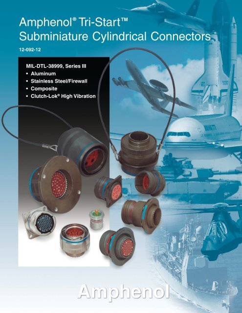
® TMAmphenol Tri-StartSubminiature Cylindrical Connectors12-092-12MIL-DTL-38999, Series III• Aluminum• Stainless Steel/Firewall• Composite• Clutch-Lok ® High Vibration
Table of ContentsPage No.Series III - The Highest Performance MIL-DTL-38999 Connector ..................... 1Tri-Start Series III Versatility and Options ......................................................... 2Shell Styles and Key Design Features .............................................................. 3Test Data .......................................................................................................... 4Specifications ................................................................................................... 5Insert Availability and Identification .............................................................. 6, 7Alternate Positioning ......................................................................................... 8Insert Arrangements ................................................................................... 9-15CrimpTVP00R/CTVP00R Wall Mounting Receptacle ......................................... 16TVP02R/CTVP02R Box Mounting Receptacle ......................................... 17TV06R/CTV06R Straight Plug .................................................................. 18TV26/MTV26 CLUTCH-LOK® Straight Plug ............................................ 19TV07R/CTV07R Jam Nut Receptacle ...................................................... 20TV01R/CTV01R Line Receptacle ............................................................. 21TV09R Flange Mounting Plug ................................................................... 22HermeticTVPS02Y Box Mounting Receptacle ........................................................ 23TVS07Y Jam Nut Receptacle ................................................................... 24TVSIY Solder Mounting Receptacle ......................................................... 25TVSIY Weld Mounting Recepacle ............................................................ 26Fail Safe, Lanyard ReleaseDesign Features, Types ............................................................................ 27D38999/29, D38999/30 Lanyard Release Plug .................................... 28-30D38999/31 TV Fail Safe Lanyard Release Plug for MIL-STD-1760 ..... 31, 32Accessories for Lanyard Release Connectors ......................................... 33AccessoriesReceptacle Protection Caps ..................................................................... 34Plug Protection Caps ............................................................................... 35Dummy Receptacles ................................................................................ 36Cable Clamps ........................................................................................... 37Universal Header Assembly for Flex Print or PC Board Connectors .. 38, 39Contacts, Sealing Plugs, Plastic/Metal Protection Caps ................................. 40Contacts (Printed Circuit Board, Wire wrap) ................................................... 41Application Tools ............................................................................................. 42How to OrderAmphenol® TV, Metal and Amphenol® TV26 CLUTCH-LOK® ................. 43D38999, TV Military, Metal and MTV26 CLUTCH-LOK® .......................... 44Amphenol® CTV, Composite .................................................................... 45D38999, CTV Military, Composite ............................................................ 46Composite Weight Comparisons .................................................................... 47Specials (Fiber Optics, Filter Protection, Flex Assemblies,PCB Applications) .................................................................................... 48Specials (Coax, Twinax, Triax Contacts, Ground Plane Connectors,Press Fit Connectors) ............................................................................. 49Specials (Quadrax Contacts) ......................................................................... 50Specials (Deep Reach Shells, Stand-off Flange Shells, Connectors withIntegral Strain Reliefs, ESD Protection, RJ Field Connectors .................. 51Sales Office and Distributor Listing ................................................................ 52For additional information concerning Amphenol Tri-Start Connectors, or if thereare special application requirements, contact your local sales office orAmphenol Aerospace40-60 Delaware Ave.Sidney, New York 13838-1395Phone: 607-563-5011 Fax: 607-563-5157www.amphenol-aerospace.comAmphenol Aerospace is a Cerfitied ISO9001 Manufacturer.
Amphenol ® Tri-StartSeries III - the highest performanceMIL-DTL-38999 connectorComposite Tri-Start,Qualified to MIL-DTL-38999, Rev. JTri-Start TM MIL-DTL-38999 Series IIIwith Metal Shells - Aluminum, Stainless Steel, Class K FirewallAmphenol ® Tri-Start MIL-DTL-38999* Series III Connectorsoffer the highest performance capabilities for both generalduty and severe environment applications. Meeting or exceedingMIL-DTL-38999 Series III requirements, the Tri-Startconnector with standard metal shells (aluminum or stainlesssteel with several finish options) offers these features:• EMI Shielding - solid metal to metal coupling, groundingfingers, electroless nickel plating, and thicker wall sectionsprovide superior EMI shielding capability of 65dB minimumat 10 GHz• Contact Protection - recessed pins in this 100% scoopproofconnector minimize potential contact damage• Moisture Resistance - improved interfacial seal designhelps prevent electrolytic erosion of contacts• Corrosion Resistance - shells of stainless steel orcadmium over nickel plating withstand a 500 hour salt sprayexposure• Vibration/Shock - operates under severe high temperaturevibration, through 200°C• Firewall Capability - available in a stainless steel shell,class RK, RS• Lockwiring Eliminated - unique, self-locking, quickcoupling connector eliminates lockwiring• Quick Coupling - completely mates and self-locks in a360° turn of the coupling nut• Inventory Support Commonality - uses standard MIL-DTL-38999 contacts, application tools, insert arrangements• Electrostatic Discharge Protection (ESD) - protection forsensitive circuitry without diodes, varistors, etc., with theuse of the Faraday Cage principal which shunts highvoltage, high current discharge events (see page 51)• Ground Plane Connectors - with metallic insert forcommon grounding of coax, triax or twinax contact outershield (see page 49)* MIL-DTL-38999 Series III supersedes MIL-C-38999 Series III.1MIL-Qualified to MIL-DTL-38999, Rev. K, the Amphenol® Composite Tri-Start Connector offers a lightweight,corrosion resistant connector with the same highperformance features as its metal counterpart. TheComposite Tri-Start Connector also includes the followingfeatures:• Lightweight - 17% – 70% weight savings(17–40% weight savings vs. aluminum)(60–70% weight savings vs. stainless steel)See Composite weight comparison chart, pg. 47.• Corrosion Resistance - available in standard MIL-DTL-38999 olive drab cadmium (175°C) and electrolessnickel plating (200°C), both withstanding 2000hours of salt spray exposure. The base material isable to withstand an indefinite exposure to salt spray.• Durability - 1500 couplings minimum (in reference toconnector couplings, not contacts)• Extended Life Contact - Mil-approved platingprocess which provides 1500 couplings minimumCLUTCH-LOK TM MIL-DTL-38999 Series IIIHigh Vibration ConnectorThe latest offering from Amphenol in MIL-DTL-38999,the CLUTCH-LOK connector offers:All advantages of stainless steel/Class K firewall Tri-Start connectors plus a unique clutch design thatactually tightens itself under vibration.Features include:• High degree of differential torque• No settling back to the next ratchet tooth• Completely intermateable with all existingMIL-DTL-38999 Series III connectors• Offers advantage in inaccessible, hard to reachareas where mating torque is difficult to apply andcomplete coupling is not verifiable by inspectionSee page 19 for description, 43 and 44 for ordering.
Amphenol ® Tri-Startoffers more versatility & optionsthan any other interconnection familyThe Tri-Start Connector is the high performance choicein the D38999 Family.Originally designed in order to increase the performance levelsof MIL-DTL-38999 Series I and II, the Series III was createdto meet high performance connector criteria.Dynamic features for performance and reliability that wereneeded for military, aerospace and ground vehicle applicationswere designed into the Series III that include:• Rapid coupling via a triple-start thread• Shell-to-shell or metal-to-metal bottoming• Improved EMI shieldingThe Tri-Start Family of connectors has grown and expandedsince its original addition to the 38999 series in order to meetever-evolving interconnection product needs. Today, the Tri-Start family has styles and options that cover a very widerange to meet not only the highest performance needs ofspace applications, but also general duty connector needs.The Tri-Start Connector Series is second to none interms of versatility and customer options.The broad porfolio includes Tri-Starts with:• Aluminum and nickel plated stainless steel shells• Class K Firewalls• Composite shells• Clutch-Lok® high vibration design• Fiber Optics• Fail-Safe Lanyard Release connectors• Variety of contact options: shielded, coax, matched impedancecoax, triax, twinax, quadrax, thermocouple, PCB tail andwire wrap• Ground plane versions and Press-fit® with compliant pins• ESD (Electrostatic Discharge) protection• Filter/Transient protection• Hermetic versions• Long reach receptacle styles• Numerous shell geometries,finishes and accessoriesSee more on Tri-Start specialson pages 48-51.Fiber Optic Multi-Channel D38999MIL-DTL-38999 withShielded Coax ContactsFilter/TransientProtectionMIL-DTL-38999 Series IIID38999 Ground Plane withMetallic Insert, PowerContacts andShielded TwinaxContactsD38999 with FlexTermination forAttachment to PCBBoardsHermetic Tri-StartMIL-DTL-38999 Series IIIMIL-DTL-38999 Lanyard“Breakaway” ConnectorQualified for MIL-STD-1760D38999 with PC TailCoax Contacts andAlignment Disc2
Amphenol ® Tri-Startshell styles and keydesign featuresCoupling NutQuick CouplingThreadRatchetWall Mount ReceptacleStraight PlugPlugShellSpring Fingers (EMI)Anti-DecouplingDeviceBox Mount ReceptacleJam Nut ReceptacleLine ReceptacleLonger Shell ReceptacleFlange Mounting PlugLanyard Release PlugSolder Mount HermeticReceptacleDesigned for PerformanceNumerous advantages in performance capability are designedinto the Amphenol Tri-Start Connector. A positive metal to metalcoupling design, grounding fingers, and electroless nickel platingprovide superior EMI shielding capability of 65 dB minimumat 10 GHz.Acme threads provide coupling durability. Thicker wall sectionsand a greater coupling surface area improve strength and shockresistance. Blunting of the thread on both the coupling nut andreceptacle eliminates cross coupling. The connector quicklymates and self locks in a 360° turn of the coupling nut.Elongated mounting holes permit the Tri-Start Connector tointermount with various existing MIL-spec box or wall mount receptacles,giving it a design replacement advantage.Shells of stainless steel, or cadmium over nickel plating preventsevere corrosion. Resistance is tested through exposure to a500 hour salt spray. Composite versions provide protection fromsalt spray exposure for 2000 hours. Other finish options are available;see how to order Tri-Start metal and Tri-Start Composite.Recessed pins minimize potential contact damage in this 100%scoop-proof connector. In a blind mating application, mating shellscannot “scoop” the pins and cause a shorting or bending of contacts.The design of the Amphenol Tri-Start interfacial seal meets theMIL-DTL-38999 Series III requirements for electrolytic erosionresistance.A rigid dielectric insert with excellent electrical characteristicsprovides durable protection to the contacts. The socket contactsare probe proof, and all contacts are rear removable. They areplated in the standard 50 micro inches minimum gold, with 100micro inches as an option and are available in standard Tri-Startinsert arrangements and special Pyle® insert arrangements insizes 10 power, 12, 16, 20 and 22D contacts. Special insert patternsare also available with larger contacts in sizes 4 and 0.Applicable Patents:Tri-Start TM Connector Patent 4,109,990.Composite Connector Patents:4,268,103; 4,648,670; 4,682,832; 4,703,987.Clutch-Lok ® Patent 6,152,753.3
Tri-Starttest dataLEAKAGE dB14012010080604020TRI-START, SERIES IIITYPICAL SHIELDING EFFECTIVENESS TEST DATAEMI/EMP SHIELDING EFFFECTIVENESS dBTESTING BY TRIAXIAL METHODNICKEL CLASS F, CLASS MTYPICAL SHIELD EFFECTIVENESS DATANICKEL CLASS F, CLASS MMIL-DTL-38999 REQUIREMENTS0100 200 300 400 500 600 700 800FREQUENCY MEGAHERTZAmphenol ® Tri-Start connectors provideEMI/EMP shielding capability which exceedsMIL-DTL-38999 Series III requirements.The TV and CTV Series III connector with standardsolid metal to metal coupling, EMI grounding fingersand conductive finishes has proven to be the ultimatein EMI/EMP shielding effectiveness. The charts illustrateshielding effectiveness data which is typicalof Tri-Start connectors tested with the nickel finish(Class F-metal, Class M-composite) over a wide frequencyrange.The vibration capability of the Tri-Start Series isshown in the chart below. This illustrates the mostsevere vibration envelope of any qualified connectoravailable today.These capabilities along with a 200°C temperaturerating and superior moisture sealing protection providethe user with a connector that can withstandthe most rigorous application.10.TRI-STARTVIBRATION CRITERIALEAKAGE dB140120100806040TRI-START, SERIES IIITYPICAL SHIELDING EFFECTIVENESS TEST DATAEMI/EMP SHIELDING EFFFECTIVENESS dBTESTING BY MODE STIRRING METHODNICKEL CLASS F, CLASS M20NICKEL CLASS F, CLASS M01 2 3 4 5TYPICAL SHIELD EFFECTIVENESS DATAMIL-DTL-38999 REQUIREMENTSFREQUENCY GIGAHERTZ6 7 8 9 10POWER SPECTRAL DENSITY G 2 /HZ1..1.01.0016dB/octave10in/sec.06 in DA.2 axes @ ambient2 axes @200˚C*(Fail Safe:2 axes @ambient)3 axes @ – 55 Cambient + 200 C*60 G's(Fail Safe: 3 axes@ ambient30 G's).00015 50 HERTZ 500 5000DOUBLE AMPLITUDE(IN) SINE VIBRATION˚˚POWER SPECTRALDENSITY (G 2 /HZ)RANDOM VIBRATIONTest data beyond 2GHz is subject to equipment variation.4* Dependant on shell finishNOTE: for test data information on the newClutch-Lok Tri-Start, high vibration connectors,consult Amphenol Aerospace.
Tri-StartspecificationsCONTACT RATINGTest Current Maximum MaximumContact Millivolt Drop MIllivolt DropSize Crimp Hermetic Crimp* Hermetic*22D 5 3 73 8520 7.5 5 55 6016 13 10 49 8512 23 17 42 8510 (Power) 33 NA 33 NA8 (Power) 46 NA 26 NA4 80 NA 23 NA0 150 NA 21 NA* When using silver plated wire.Crimp Well DataHermetic DataContact Nominal Min. WellSize Well Diameter Well Depth Well Diameter Depth22D .0345 ± .0010 .141 .036+ .004– .000.09420 .047 ± .001 .209 .044+ .004– .000.12516 .067 ± .001 .209 .078+ .004– .002.14112 .100 ± .002 .209 .116+ .004– .002.14110 (Power) .137 ± .002 .355 NA NA8 .181 ± .002 .490 NA NA4 .281 ± .002 .490 NA NA0 .453 ± .002 .585 NA NASERVICE RATINGSuggested Oper. VoltageService (Sea Level) Test Voltage Test Voltage Test Voltage Test VoltageRating AC (RMS) DC (Sea Level) 50,000 Ft. 70,000 Ft. 110,000 Ft.M 400 550 1300 VRMS 550 VRMS 350 VRMS 200 VRMSN 300 450 1000 VRMS 400 VRMS 260 VRMS 200 VRMSI 600 850 1800 VRMS 600 VRMS 400 VRMS 200 VRMSII 900 1250 2300 VRMS 800 VRMS 500 VRMS 200 VRMSPlease note that the establishment of electrical safety factors is left entirely in the designer’s hands, since he is in the best position to know what peak voltage,switching surges, transients,etc. can be expected in a particular circuit.FINISH DATANon-Hermetic Shell ComponentsService ClassFinish Military ProprietaryAnodic Coating (Non-Conductive) C RX**Electroless NickelF (Metal)M (Composite)RFOlive Drab Cadmium Plate Nickel BaseW (Metal)J (Composite)RWStainless Steel with Nickel Plate S RSStainless Steel K RK** Add Suffix (005) to part number.Hermetic Shell ComponentsService ClassMaterial / Finish Military ProprietaryStainless Steel Y YStainless Steel with Nickel Plate N YN5
Tri-Startinsert availability and identificationAMPHENOL TRI-START INSERT ARRANGEMENTSContact SizeShell Military Service Total 22D 20 16 12 12 10 8 8††Size/Arrg. Shell Crimp Hermetics* Rating Contacts (Coax) (Power) (Coax) (Twinax)9-5★ A Grounded 1 19-35 A X P M 6 69-94 ■ A ✦ M 2 29-98 A X P I 3 311-2★ B ✦ I 2 211-5 B ✦ P I 5 511-35 B X P M 13 1311-54 B X II 4 411-98 B X P I 6 611-99 B X I 7 713-4★ C X P I 4 413-8 C X P I 8 813-13 C I, Fiber Optic 4 2 213-35 C X P M 22 2213-98 C X P I 10 1015-4 ■ D ✦ I 4 415-5★ D X P II 5 515-15 D X P I 15 14 115-18 D X P I 18 1815-19 D ✦ P I 19 1915-35 D X P M 37 3715-97 D X P I 12 8 417-2 E X M 39 38 117-6 E X P I 6 617-8★ E X P II 8 817-22★ E ✦ Coax 4 2 217-26 E X P I 26 2617-35 E X P M 55 5517-99 E X I 23 21 219-11★ F X P II 11 1119-18 F X M 18 14 419-28 F X I 28 26 219-31 F ✦ M 15 12 1 219-32 F X P I 32 3219-35 F X P M 66 6621-11★ G X I 11 1121-16★ G X P II 16 1621-29 G X I 27 19 4 421-35 G X P M 79 7921-39 G X P I 39 37 221-41 G X P I 41 4121-75★ ✧ G X M 4 4 (See note)21-79 G X II 19 17 223-6 ★■ H P M 6 623-14 H ✦ I 14 1423-21★ H X P II 21 21X Completely tooled.• Majority of tooling is completed (contact Amphenol Aerospace for availabilty).✦ Not tooled for 02-R.P Pin inserts only (contact Amphenol Aerospace for socket availability).★ Ground plane proprietary option available. Arrg. 9-5 is exclusivelyground plane type. See pg. 49 for further information on ground plane connectors.■ Not Mil-Qualified.✧ 21-75 is Mil-Qualified with twinax contacts only.Note: MS connector 21-75 is supplied with size 8 twinax.Proprietary connector 21-75 is supplied with size 8 coax.6* Hermetic inserts - solder termination standard. (Contact AmphenolAerospace for optional PCB or eyelet termination).** Two size 16 contacts dedicated to fiber optics. Consult AmphenolAerospace catalog 12-352 for fiber optic information.*** For use in MIL-STD-1760 applications (see pages 31 & 32).† For RG 180/U and RG 195/U cables only.†† Size 8 Coax and Twinax are interchangeable.
Tri-Start and Specialsinsert availability and identificationTRI-START ARRANGEMENTS, CONT.Contact SizeShell Military Service Total 22D 20 16 12 12 10 8 8††Size/Arrg. Shell Crimp Hermetics* Rating Contacts (Coax) (Power) (Coax) (Twinax)23-35 H X P M 100 10023-53 H X P I 53 5323-54 ■ H ✦ M 53 40 9 423-55 H ✦ P I 55 5525-4 J X P I 56 48 825-7 J ✦ Twinax 99 97 225-8★ J ✦ Twinax 8 825-11*** J ✦ N 11 2 925-17 ■ J ✦ M 42 36 625-19★ J X P I 19 1925-20*** J ✦ N 30 10 13** 4 325-24★ J X P I 24 12 1225-26 ■ J ✦ I 25 16 5 425-29★ J X I 29 2925-35 J X P M 128 12825-37★ ■ J ✦ I 37 3725-41 J X N/Inst. 41 22 3 11 2 325-43 J ✦ I 43 23 2025-46 ■ J ✦ I 46 40 4 2†25-61 J X P I 61 6125-90 J X I 46 40 4 225-F4 J ✦ M/I 66 49 13 4SPECIAL ARRANGEMENTSContact SizeShell Military Service Total Comments 22D 20 16 12 8††Size/Arrg. Shell Crimp Hermetics* Rating Contacts (Twinax)9-2 A X I 2 formerly Pyle 215-4 D X II 4 formerly Pyle 415-25 D X M 25 formerly Pyle 22 317-20 E X M 20 formerly Pyle 16 421-12 G X I 12 formerly Pyle 3 921-21 G X M/Inst. 41 improved sealing 32 921-99 G X M 16 formerly Pyle 5 1125-90 J X I 46 formerly Pyle 40 4 225-92 J X M 101 formerly Pyle 92 925-97 J X M 42 formerly Pyle 26 3 13SPECIAL ARRANGEMENTS(insert arrangements requiring non-standard shells or larger contacts)Contact SizeShell Service Total 22D 20 8 4 0Size/Arrg. Crimp Hermetics* Rating Contacts25-16 X M 8 6 225-155 X M 155 15525L-3 X II 3 1 225L-7 X II 7 733-3 X II 3 1 233-5 X II 5 533-6 X II 6 2 437-5 X II 4 47X Completely tooled.• Majority of tooling is completed (contact AmphenolAerospace for availabilty).✦ Not tooled for 02-R.P Pin inserts only (contact Amphenol Aerospace forsocket availability).★ Ground plane proprietary option available.Arrangement 9-5 is exclusively ground plane type.■ Not Mil-Qualified.* Hermetic inserts - solder termination standard.(Contact Amphenol Aerospace for optional PCB oreyelet termination).** Two size 16 contacts dedicated to fiber optics.Consult Amphenol Aerospace catalog 12-352for fiber optic information.*** For use in MIL-STD-1760 applications (pgs. 31 & 32).† For RG 180/U and RG 195/U cables only.†† Size 8 Coax and Twinax are interchangeable.Note: 25L-3 and 25L-7 require longer shells.
Tri-Startalternate positioningMaster Key/Keyway PositionAR° BR° CR° DR°Key & keyway or or or orShell arrangement AP° BP° CP° DP°Size identification letter BSC BSC BSC BSCN 105 140 215 265A 102 132 248 3209 B 80 118 230 312C 35 140 205 275D 64 155 234 304E 91 131 197 240N 95 141 208 23611, A 113 156 182 29213, B 90 145 195 252and C 53 156 220 25515 D 119 146 176 298E 51 141 184 242N 80 142 196 293A 135 170 200 31017 B 49 169 200 244and C 66 140 200 25719 D 62 145 180 280E 79 153 197 272N 80 142 196 29321, 23 A 135 170 200 31025, 25L B 49 169 200 24433, 37 C 66 140 200 257D 62 145 180 280E 79 153 197 272A plug with a given rotation letter will mate with a receptacle withthe same rotation letter. The angles for a given connector are thesame whether it contains pins or sockets. Inserts are not rotatedin conjunction with the master key/keyway.ARBSC˚BRBSC˚DRBSC˚CRBSC˚MAINKEYWAYPLUG(front face shown)RECEPTACLE(front face shown)MAINKEYWAY˚APBSCBP˚BSC˚CPBSC˚DPBSC8
Tri-Startinsert arrangementsfront face of pin inserts illustrated5 14 6 23B ACABBAEDCAB10 19 11 23813 127 46 5DCABInsert Arrangement 9-5 9-35 9-94 9-98 11-2 11-5 11-35 11-54Service Rating Grounded M M I I I M IINumber of Contacts 1 6 2 3 2 5 13 4Contact Size 8 Twinax 22D 20 20 16 20 22D 22DAEDF BCEDFGCABDABCGFEABHCDBCDA12122AH BG CK JF DEDCABInsert Arrangement 11-98 11-99 13-4 13-8 13-13 13-35 13-98 15-4Service Rating I I I I I, Fiber Optic M I INumber of Contacts 6 7 4 8 2 2 22 10 4Contact Size 20 20 16 20 16 12 22D 20 12Dedicated toFiber OpticsEDACBKL AMBJHR NPCDG EFL AK M N BT U PJCS RHDGF EM ABL N PCK U V RJ T SDHEG F31121KJAL BHCM DGF EInsert Arrangement 15-5 15-15 15-18 15-19 15-35 15-97Service Rating II I I I M INumber of Contacts 5 14 1 18 19 37 8 4Contact Size 16 20 16 20 20 22D 20 1617130116DEAFCBFGEABHDCDACBAR BP S T CaUbNDZc VMEY WL XGFKJ HInsert Arrangement 17-2 17-6 17-8 17-22 17-26Service Rating M I II Coax INumber of Contacts 38 1 6 8 2 2 26Contact Size 22D 8 Twinax 12 16 12 Coax 8 Coax 209CONTACT LEGEND8 10 12 16 20 22D
Tri-Startinsert arrangementsfront face of pin inserts illustrated171032404 254713535552916 31 4624 39LRKJAP S TYN ZXM WHGBU CVFDEJHKGLFEABCDPNMLKRJASHTUGBCDEFInsert Arrangement 17-35 17-99 19-11 19-18Service Rating M I II MNumber of Contacts 55 21 2 11 14 4Contact Size 22D 20 16 16 22D 8 TwinaxT AS U BRdVCPNcbeZWXDEMa Y FL J GK HV fWUhNSRAKMCBgETSR eP d jNcbM aLKBCUVAfghWXDEY FZJ GH25 3417 4310514581642366639165724 5033 42Insert Arrangement 19-28 19-31 19-32 19-35Service Rating I M I MNumber of Contacts 26 2 2 1 12 32 66Contact Size 20 16 8 Coax 12 22D 20 22DJHKGFLEABCDLKSJRHGAMNPEFBDC19 11817 25161524 271423131211 10232045626 212278921151797161413111Insert Arrangement 21-11 21-16 21-29 21-35Service Rating I II I MNumber of Contacts 11 16 19 4 4 79Contact Size 12 16 20 16 12 22D10CONTACT LEGEND8 10 12 16 20 22D
Tri-Startinsert arrangementsfront face of pin inserts illustratedAU V WBTCjXYS iDk Zh rm a ER g q n bPfc FNdepGMHL JKAV W BUCjXY DT i ksZm EShtran FRg q p bc GPfe dNHMJL KDCABSRPN UMLTKJAHBVGCDEFInsert Arrangment 21-39 21-41 21-75 21-79Service Rating I I M IINumber of Contacts 37 2 41 4 17 2Contact Size 20 16 20 8 Twinax 22D 8 CoaxEDFACBJHKGPNAFLMBCDENMWLK VUJHGPXABRCSDTEF123456725 46 6716 35 56 77886159324 45 66 8534 55 769495 96979899100Insert Arrangement 23-6 23-14 23-21 23-35Service Rating M I II MNumber of Contacts 6 14 21 100Contact Size 8 Twinax 12 16 22DAR S T BUP m n p VCkWN AABBqDzrM h GG CC X Ey HH sL g FF DD YxFEE tf w uaZK e vd bJ c GH24 1 2 321 2223 2542043 44 262742 5251945 46284162951 53 47403039 50 49 48 31718 383217 37 33 836 3416910151413351112AT U V BW CSXm n p YAA q DkR z GG BB r Zj y HH CCEFFaPsi EE DDxFt bN h w ucg vd GfMeHLK JInsert Arrangement 23-53 23-54 23-55Service Rating I M INumber of Contacts 53 40 9 4 55Contact Size 20 22D 16 12 2011CONTACT LEGEND8 10 12 16 20 22D
Tri-Startinsert arrangementsfront face of pin inserts illustratedAZBa CY wvbc DX u GGxEFFdW tHH ye FVs EE LL JJ z fr DD KK AAUg Gq CC BBhTHpkSnm JR N KP LM29 642272167946785247419418 3267 8141 5925 7542 6019 3368 826 2653 76 99159321842878FGEAHBDCInsert Arrangement 25-4 25-7 25-8Service Rating I Twinax TwinaxNumber of Contacts 48 8 97 2 8Contact Size 20 16 22D 8 Twinax 8 TwinaxGHLAJKBDCRPSNZTaUbcABVdq r s ew tpfn v ugkm hCDEWFGKJLUMNTVAPRSBCDEFEMYLKJXHHGFInsert Arrangement 25-11*** 25-17 25-19Service Rating N M INumber of Contacts 2 9 36 6 19Contact Size 20 10 Power 22D 8 Twinax 12SRP ZN Y 47M3XLKA BCT D516WHJU E2FVGPNYMXLKRZWJASaVHBTUGCDEF101191281318 19 20 1425 212417 231617222634155Insert Arrangement 25-20*** 25-24 25-26Service Rating N I INumber of Contacts 10 13 3 4 12 12 16 5 4Contact Size 20 16 8 Twinax 12 Coax 16 12 20 12 8 Coax(With Matched Impedance)*** For use in MIL-STD-1760 applications (see pages 31 and 32).12CONTACT LEGEND8 10 12 16 20 22D
Tri-Startinsert arrangementsfront face of pin inserts illustratedRPbNaMZLKSfYJATcdeXHBCUDVW EFG5948 71362582948 15105 115141257128141212411435 58 70 81 1044793UTSfge qRdPpcNbMLA BVCWhDkXrEm YFn Za GK HJInsert Arrangement 25-29 25-35 25-37Service Rating I M INumber of Contacts 29 128 37Contact Size 16 22D 16PYNdXnMW mc sLkK jbVJABRCeZSp Dq g Ttar hEiUFGHABX Y Z CWpna DVEmbUw qFkcv x rT hd Gu t sSHgeR fJPKN LMVUsrTqS pWtAARznmP ykNhMLAXBu Y CvZDabEwcFdx GegHfJKInsert Arrangement 25-41 25-43 25-46Service Rating N/Inst. I INumber of Contacts 22 3 11 2 3 23 20 40 4 2Contact Size 22D 20 16 12 Coax 8 Twinax 20 16 20 16 8 Coax†Z ABY avbX ucCt GGWHH w d DsFFxNN JJEVeEE PPU r MM KK yf FLLqz g GTDDp BB AA h HCCS ni JR m k jPMKN LVsUrTqSzpAAWR nP mykNhMLtAX BuY Cv ZDaEbwc Fxd Ge Hg fKJ26 27 1 2325 38 39 40 28 29 4243037 50 51 41 42 4323 363161 62 63 52 53 54222160 66 64 552049 59 65 56351958 57481847 46171634 1315 14455632744 8933101112Insert Arrangement 25-61 25-90 25-F4Service Rating I I Size 22D = M, Balance = INumber of Contacts 61 40 4 2 49 13 4Contact Size 20 20 16 8 Twinax 22D 16 12† Coax contacts for RG180/U or RG195/U cable.13CONTACT LEGEND8 10 12 16 20 22D
Specialinsert arrangementsfront face of pin inserts illustratedBAABDC21313144 15162322125 24176212518 117 19 2089 10A 1613 2 15 14413BD5126 7 C 10 118 9Insert Arrangement 9-2 15-4* 15-25 17-20Service Rating I II M MNumber of Contacts 2 4 22 3 16 4Contact Size 20 16 22D 16 22D 12CBDALKJMFHG1JA9210H23 24 11 12B22 25 2632 138321 31 27 1415G20 30 28C19 29 16718 174CDABLMNPJKSRHGEF6E5DEFInsert Arrangement 21-12 21-21 21-99Service Rating I M/Inst. MNumber of Contacts 3 9 32 9 5 11Contact Size 20 12 22D 12 22D 1266 23 1278 56 45 35466724139789FG79A M90557 36BLN981R P e dChSgfcj w u tTvkn ps bD mrU V X Z a3EW YH1014KJInsert Arrangement 25-92 25-97Service Rating M MNumber of Contacts 92 9 26 3 13Contact Size 22D 16 22D 16 12NOTE: Some specials shown here were formerly known as Pylearrangements.Consult Amphenol for how to order information forconnectors with these inserts.For further information on special arrangements consultAmphenol Aerospace, Sidney NY.* Pyle 15-4 does not mate with Amphenol Tri-Start 15-4 insert.14CONTACT LEGEND8 10 12 16 20 22D
Specialinsert arrangements requiring non-standardshells or larger contactsfront face of pin inserts illustratedHGDFB21324457698294107114151222334558708395CAECA119 108130 120140131149141155150BInsert Arrangement 25-16 25-155 25L-3Service Rating M M IINumber of Contacts 6 2 155 1 2Contact Size 20 4 22D 8 4FAAEGBCAEBDCBDCInsert Arrangement 25L-7 33-3 33-5Service Rating II II IINumber of Contacts 7 1 2 5Contact Size 8 4 0 4AAEDFBDCCInsert Arrangement 33-6 37-5Service Rating II IINumber of Contacts 2 4 4Contact Size 8 4 0BNOTE: Some specials shown herewere formerly known as Pylearrangements. Consult Amphenol forhow to order information forconnectors with these inserts.Consult Amphenol Aerospace forlonger shell drawings.15CONTACT LEGEND0 4 8 22D
TVP00R (D38999/20) – crimp, metalCTVP00R (D38999/20) – crimp, compositewall mounting receptacleS2 PLACESR 12 PLACESR 22 PLACESBTHREADLL (TV)LL 1 (CTV)M (TV)M 1(CTV)AAL (TV)L 1 (CTV)V THREADVIEW DFOR SIZE 8 COAXIAL ONLY,RELATIVE TO –A–.861 MAX21.87 MAX(TV)Part number reference.See how to order, pages 43-46to complete.TVP00RW-XX-XXXTVPS00RK-XX-XXXTVPS00RF-XX-XXXTVPS00RS-XX-XXXCTVP00RW-XX-XXXCTVPS00RF-XX-XXXD38999/20PANEL HOLEDIMENSIONSD.909 MAX23.09 MAX(CTV)TT4 PLACES.005 M.13 MT4 PLACESREDBAND †BLUEBAND ††Z (TV)Z 1(CTV)–A–VIEW DFOR SIZE 8 TWINAX ONLY,RELATIVE TO –A–1.037 MAX26.34 MAX(TV)A 1BACK PANELMOUNTING1.240 MAX31.50 MAX† Red band indicates fully mated†† Blue band indicates rear release contact retention system1.084 MAX27.53 MAX(CTV)A 2FRONT PANELMOUNTINGMS B Thread M M 1 A 1 Dia. A 2 Dia. AA LLShell Class 2A L L 1 +.000 +.000 T Z Z 1 Back Front Max. +.006 LL 1 TTShell Size 0.1P-0.3L-TS Max. Max. –.005 –.005 R 1 R 2 S +.008 Max. Max Panel Panel Panel –.000 ±.005 +.008Size Code (Plated) (TV) (CTV) (TV) (CTV) Max. –.006 (TV) (CTV) Mount Mount Thickness (TV) (CTV) –.0069 A .6250 .469 .514 .820 .775 .719 .594 .948 .128 .153 .198 .650 .510 .234 .905 .913 .21611 B .7500 .469 .514 .820 .775 .812 .719 1.043 .128 .153 .198 .800 .620 .234 .905 .913 .19413 C .8750 .469 .514 .820 .775 .906 .812 1.137 .128 .153 .198 .910 .740 .234 .905 .913 .19415 D 1.0000 .469 .514 .820 .775 .969 .906 1.232 .128 .153 .198 1.040 .900 .234 .905 .913 .17317 E 1.1875 .469 .514 .820 .775 1.062 .969 1.323 .128 .153 .198 1.210 1.010 .234 .905 .913 .19419 F 1.2500 .469 .514 .820 .775 1.156 1.062 1.449 .128 .153 .198 1.280 1.130 .234 .905 .913 .19421 G 1.3750 .500 .545 .790 .745 1.250 1.156 1.575 .128 .183 .228 1.410 1.250 .204 .905 .911 .19423 H 1.5000 .500 .545 .790 .745 1.375 1.250 1.701 .154 .183 .228 1.530 1.360 .204 .905 .911 .24225 J 1.6250 .500 .545 .790 .745 1.500 1.375 1.823 .154 .183 .228 1.660 1.470 .204 .905 .911 .242MillimetersMS M M 1 A 1 Dia. A 2 Dia. LLShell L L 1 +.00 +.00 T V Z Z 1 Back Front +.15 LL 1 TTShell Size Max. Max. –.13 –.13 R 1 R 2 S +.20 Thread Max. Max. Panel Panel AA –.00 ±.13 +.20Size Code (TV) (CTV) (TV) (CTV) Max –.13 Metric (TV) (CTV) Mount Mount Max. (TV) (CTV) –.139 A 11.91 13.06 20.83 19.69 18.26 15.09 24.1 3.25 M12X1-6g 3.89 5.03 16.66 13.11 5.94 22.99 23.19 5.4911 B 11.91 13.06 20.83 19.69 20.62 18.26 26.5 3.25 M15X1-6g 3.89 5.03 20.22 15.88 5.94 22.99 23.19 4.9313 C 11.91 13.06 20.83 19.69 23.01 20.62 28.9 3.25 M18X1-6g 3.89 5.03 23.42 19.05 5.94 22.99 23.19 4.9315 D 11.91 13.06 20.83 19.69 24.61 23.01 31.3 3.25 M22X1-6g 3.89 5.03 26.59 23.01 5.94 22.99 23.19 4.3917 E 11.91 13.06 20.83 19.69 26.97 24.61 33.7 3.25 M25X1-6g 3.89 5.03 30.96 25.81 5.94 22.99 23.19 4.9319 F 11.91 13.06 20.83 19.69 29.36 26.97 36.9 3.25 M28X1-6g 3.89 5.03 32.94 28.98 5.94 22.99 23.19 4.9321 G 12.70 13.84 20.07 18.92 31.75 29.36 40.1 3.25 M31X1-6g 4.65 5.79 36.12 32.16 5.18 22.99 23.14 4.9323 H 12.70 13.84 20.07 18.92 34.93 31.75 43.3 3.91 M34X1-6g 4.65 5.79 39.29 34.93 5.18 22.99 23.14 6.1525 J 12.70 13.84 20.07 18.92 38.10 34.93 46.4 3.91 M37X1-6g 4.65 5.79 42.47 37.69 5.18 22.99 23.14 6.15InchesAll dimensions for reference onlyDesignates true position dimensioning16
TV01R – crimp, metalCTV01R – crimp, compositeline receptacleGG (TV)GG 1(CTV)BTHREADLL (TV)LL 1 (CTV)M (TV)M 1(CTV).280 MIN FULL THD7.11 MIN FULL THDV THREADVIEW DFOR SIZE 8 COAXIAL ONLY,RELATIVE TO –A–.861 MAX21.87 MAX(TV)Part number reference.See how to order, 43-45 tocomplete.TV01RW-XX-XXXTVS01RF-XX-XXXCTV01RW-XX-XXXCTVS01RF-XX-XXXD.909 MAX23.09 MAX(CTV)S (TV)S 1(CTV)2 PLACESREDBAND †BLUEBAND ††Z (TV)Z 1(CTV)–A–L (TV)L 1 (CTV)VIEW DFOR SIZE 8 TWINAX ONLY,RELATIVE TO –A–1.037 MAX26.34 MAX(TV)1.240MAX31.50 MAX† Red band indicates fully mated†† Blue band indicates rear release contact retention system1.084 MAX27.53 MAX(CTV)MS M M 1 LLShell B Thread +.000 +.000 L L 1 S S 1 Z Z 1 GG GG 1 +.006 LL 1Shell Size 0.1P-0.3L-TS-2A –.005 –.005 Max. Max. ±.010 ±.010 Max. Max. ±.010 ±.010 –.000 ±.005Size Code (Plated) (TV) (CTV) (TV) (CTV) (TV) (CTV) (TV) (CTV) (TV) (CTV) (TV) (CTV)9 A .6250 .820 .775 .469 .514 .675 .635 .153 .198 .812 .699 .905 .91311 B .7500 .820 .775 .469 .514 .800 .765 .153 .198 .905 .875 .905 .91313 C .8750 .820 .775 .469 .514 .925 .885 .153 .198 1.093 1.007 .905 .91315 D 1.0000 .820 .775 .469 .514 1.050 1.100 .153 .198 1.219 1.140 .905 .91317 E 1.1875 .820 .775 .469 .514 1.238 1.197 .153 .198 1.375 1.229 .905 .91319 F 1.2500 .820 .775 .469 .514 1.300 1.260 .153 .198 1.469 1.380 .905 .91321 G 1.3750 .790 .745 .500 .545 1.425 1.385 .183 .228 1.625 1.493 .905 .91123 H 1.5000 .790 .745 .500 .545 1.550 1.510 .183 .228 1.750 1.626 .905 .91125 J 1.6250 .790 .745 .500 .545 1.675 1.635 .183 .228 1.875 1.777 .905 .911MillimetersMS M M 1 LLShell +.00 +.00 L L 1 S S 1 V Z Z 1 GG GG 1 +.15 LL 1Shell Size –.13 –.13 Max Max ±.25 ±.25 Thread Max Max ±.25 ±.25 –.00 ±.13Size Coded (TV) (CTV) (TV) (CTV) (TV) (CTV) Metric (TV) (CTV) (TV) (CTV) (TV) (CTV)9 A 20.83 19.69 11.91 13.06 17.15 16.13 M12X1-6g 3.89 5.03 20.62 17.75 22.99 23.1911 B 20.83 19.69 11.91 13.06 20.32 19.43 M15X1-6g 3.89 5.03 22.99 22.22 22.99 23.1913 C 20.83 19.69 11.91 13.06 23.50 22.47 M18X1-6g 3.89 5.03 27.76 25.57 22.99 23.1915 D 20.83 19.69 11.91 13.06 26.67 27.94 M22X1-6g 3.89 5.03 30.96 28.95 22.99 23.1917 E 20.83 19.69 11.91 13.06 31.45 30.40 M25X1-6g 3.89 5.03 34.93 31.21 22.99 23.1919 F 20.83 19.69 11.91 13.06 33.02 32.00 M28X1-6g 3.89 5.03 37.31 35.05 22.99 23.1921 G 20.07 18.92 12.70 13.84 36.20 35.18 M31X1-6g 4.65 5.79 41.28 37.92 22.99 23.1423 H 20.07 18.92 12.70 13.84 39.37 38.35 M34X1-6g 4.65 5.79 44.45 41.30 22.99 23.1425 J 20.07 18.92 12.70 13.84 42.55 41.53 M37X1-6g 4.65 5.79 47.63 45.13 22.99 23.14All dimensions for reference onlyInches21
TV09R – crimp, metalflange mounting plugPart number reference.See how to order, page 43 tocomplete.TV09RW-XX-XXXTVS09RF-XX-XXX.190 +.010–.0004.82 +.26–.00GBLUEBAND †RVIEW DFOR SIZE 8 COAXIAL ONLY,RELATIVE TO –A–1.656 MAX42.06 MAXDQRGG3.59 MAX9.12 MAX.591 +.003–.00015.01+.08–.00BTHREAD–A–.138-32UNC-2BHELICAL COIL.005 M.13 MVIEW DFOR SIZE 8 TWINAX ONLY,RELATIVE TO –A–1.797 MAX45.64 MAX† Blue band indicates rear release contact retention systemInchesMS B Thread Q GGShell Shell Size 0.1P-0.3L-TS-2A G Dia. R Dia.Size Coded (Plated) ±.060 Max ±.0059** A .6250 1.106 .859 1.038 1.83811 B .7500 1.106 .969 1.115 1.94813** C .8750 1.106 1.141 1.240 2.12415 D 1.0000 1.106 1.266 1.327 2.24817 E 1.1875 1.106 1.391 1.417 2.37519 F 1.2500 1.356 1.500 1.557 2.49521 G 1.3750 1.356 1.625 1.624 2.56823 H 1.5000 1.356 1.750 1.713 2.72325 J 1.6250 1.356 1.875 1.801 2.848MillimetersMS Q GGShell Shell Size G Dia. R Dia.Size Code ±1.52 Max ±.139** A 28.09 21.82 26.37 46.6911 B 28.09 24.62 28.32 49.4813** C 28.09 28.98 31.50 53.9515 D 28.09 32.16 33.71 57.1017 E 28.09 35.33 35.99 60.3319 F 34.44 38.10 39.55 63.3721 G 34.44 41.28 41.25 65.2323 H 34.44 44.45 43.51 69.1625 J 34.44 47.63 45.75 72.34All dimensions for reference only** Partially tooled. Consult Amphenol Aerospace for availabilityDesignates true position dimensioning22
TVPS02Y (D38999/21) – hermetic, metalbox mounting receptaclePart number reference.See how to order, pages 43, 44to complete.TVPS02Y-XX-XXXTVPS02YN-XX-XXXD38999/21S2 PLACESR12 PLACESR22 PLACES.913 +.011–.00023.19 +.28–.00.093 +.006–.0002.36 +.15–.001TT4 PLACES.005 M.13 MT4 PLACESB THREADREDBAND†.250 MAX6.35 MAX† Red band indicates fully matedNOTE: Consult Amphenol Aerospace for availability of non-glass-sealed versionswith printed circuit tail contacts.InchesMS B ThreadShell Class 2A T TTShell Size 0.1P-0.3L-TS R1 R2 S +.008 +.008Size Code (Plated) ±.010 –.006 –.0069 A .6250 .719 .594 .938 .128 .21611 B .7500 .812 .719 1.031 .128 .19413 C .8750 .906 .812 1.125 .128 .19415 D 1.0000 .969 .906 1.219 .128 .17317 E 1.1875 1.062 .969 1.312 .128 .19419 F 1.2500 1.156 1.062 1.438 .128 .19421 G 1.3750 1.250 1.156 1.562 .128 .19423 H 1.5000 1.375 1.250 1.688 .154 .24225 J 1.6250 1.500 1.375 1.812 .154 .242MillimetersMS T TTShell Shell Size R 1 R 2 S +.20 +.20Size Code ±.25 –.15 –.159 A 18.26 15.09 23.83 3.25 5.4911 B 20.62 18.26 26.19 3.25 4.9313 C 23.01 20.62 28.58 3.25 4.9315 D 24.61 23.01 30.96 3.25 4.3917 E 26.97 24.61 33.32 3.25 4.9319 F 29.36 26.97 36.53 3.25 4.9321 G 31.75 29.36 39.67 3.25 4.9323 H 34.93 31.75 42.88 3.91 6.1525 J 38.10 34.93 46.02 3.91 6.15All dimensions for reference only Designates true position dimensioning23
TVS07Y (D38999/23) – hermetic, metaljam nut receptaclePart number reference.See how to order, pages 43, 44to complete.TVS07Y-XX-XXXTVS07YN-XX-XXXD38999/23CT •PANEL THICKNESS.062 MIN .125 MAX1.57 MIN 3.18 MAXLPANEL HOLEDIMENSIONSD 1 D 2A•KKHS2 PLACESB THREADREDBAND †K REFSHELL SIZES 9/11 – .871 22.12SHELL SIZES 13/25 – .878 22.30.200 MAX5.08 MAXJAM NUTD-HOLEMOUNTING† Red band indicates fully mated★ . 059 dia min.3 lockwire holes1.5 dia min.Formed lockwire hole design (6 holes) is optional.MS B Thread HShell A• Class 2A D 1 D 2 Hex T• KKShell Size +.000 0.1P-0.3L-TS C +.010 +.000 +.017 L S +.010 +.011Size Code –.010 (Plated) Max –.000 –.010 –.016 Max ±.010 –.000 –.0009 A .669 .6250 1.199 .700 .670 .875 .357 1.062 .697 .64211 B .769 .7500 1.386 .825 .770 1.000 .357 1.250 .822 .76613 C .955 .8750 1.511 1.010 .955 1.188 .357 1.375 1.007 .89215 D 1.084 1.0000 1.636 1.135 1.085 1.312 .357 1.500 1.134 1.01817 E 1.208 1.1875 1.761 1.260 1.210 1.438 .357 1.625 1.259 1.14219 F 1.333 1.2500 1.949 1.385 1.335 1.562 .381 1.182 1.384 1.26821 G 1.459 1.3750 2.073 1.510 1.460 1.688 .381 1.938 1.507 1.39223 H 1.575 1.5000 2.199 1.635 1.585 1.812 .381 2.062 1.634 1.51825 J 1.709 1.6250 2.323 1.760 1.710 2.000 .381 2.188 1.759 1.642InchesMillimetersMS A• D 1 D 2 H Hex T• KKShell Shell Size +.00 C +.25 +.00 +.43 L S +.25 +.28Size Code –.25 Max –.00 –.25 –.41 Max ±.25 –.00 –.009 A 16.99 30.45 17.78 17.02 22.23 9.07 26.97 17.70 16.3111 B 19.53 35.20 20.96 19.59 25.40 9.07 31.75 20.88 19.4613 C 24.26 38.38 25.65 24.26 30.18 9.07 34.93 25.58 22.6615 D 27.53 41.55 28.83 27.56 33.32 9.07 38.10 28.80 25.8617 E 30.68 44.73 32.01 30.73 36.53 9.07 41.28 31.98 29.0119 F 33.86 49.50 35.18 33.91 39.67 9.68 46.02 35.15 32.2121 G 37.06 52.65 38.35 37.08 42.80 9.68 49.23 38.28 35.3623 H 40.01 55.85 41.53 40.26 46.02 9.68 52.37 41.50 38.5625 J 43.41 59.00 44.70 43.43 50.80 9.68 55.58 44.68 41.71All dimensions for reference only• D shaped panel cut-out dimensions24
TVSIY (D38999/25) – hermetic, metalsolder mounting receptaclePart number reference.See how to order, pages 43, 44to complete.TVSIY-XX-XXXTVSIYN-XX-XXXD38999/25L.031+.006–.005.79 +.15–.13MKKGGB THREADRED BAND †.375 MAX9.53 MAX† Red band indicates fully matedMS B Thread GG KKShell Class 2A L M Dia. Dia.Shell Size 0.1P-0.3L-TS +.011 +.006 +.011 +.001Size Code (Plated) –.005 –.005 –.010 –.0059 A .6250 .806 .125 .750 .67211 B .7500 .806 .125 .844 .78113 C .8750 .806 .125 .969 .90615 D 1.0000 .806 .125 1.094 1.03117 E 1.1875 .806 .125 1.218 1.15619 F 1.2500 .806 .125 1.312 1.25021 G 1.3750 .806 .125 1.438 1.37523 H 1.5000 .838 .156 1.563 1.50025 J 1.6250 .838 .156 1.688 1.625MillimetersGGKKMS L M Dia. Dia.Shell Shell Size +.28 +.15 +.28 +.03Size Code –.00 –.13 –.25 –.139 A 20.47 3.18 19.05 17.0711 B 20.47 3.18 21.44 19.8413 C 20.47 3.18 24.61 23.0115 D 20.47 3.18 27.79 26.1917 E 20.47 3.18 30.94 29.3619 F 20.47 3.18 33.32 31.7521 G 20.47 3.18 36.53 34.9323 H 21.29 3.96 39.70 38.1025 J 21.29 3.96 42.88 41.28All dimensions for reference onlyInches25
TVSIY (D38999/27) – hermetic, metalweld mounting receptaclePart number reference.See how to order, pages 43, 44to complete.TVSIY-XX-XXXTVSIYN-XX-XXXD38999/27GGLM.375 MAX9.53 MAXB THREADRED BAND †† Red band indicates fully matedInchesMS B Thread GGShell Class 2A L M Dia.Shell Size 0.1P-0.3L-TS +.011 +.006 +.010Size Code (Plated) –.000 –.005 –.0009 A .6250 .806 .125 .97311 B .7500 .806 .125 1.09513 C .8750 .806 .125 1.22115 D 1.0000 .806 .125 1.34717 E 1.1875 .806 .125 1.43419 F 1.2500 .806 .125 1.57921 G 1.3750 .806 .125 1.72123 H 1.5000 .838 .156 1.88625 J 1.6250 .838 .156 1.973MillimetersGGMS L M Dia.Shell Shell Size +.28 +.15 +.25Size Code –.00 –.13 –.009 A 20.47 3.18 24.7111 B 20.47 3.18 27.8113 C 20.47 3.18 31.0115 D 20.47 3.18 34.2117 E 20.47 3.18 36.4219 F 20.47 3.18 40.1121 G 20.47 3.18 43.7123 H 21.29 3.96 47.9025 J 21.29 3.96 50.11All dimensions for reference only26
TV Breakaway Fail Safe Connectorsquick-disconnect with an axial pull of lanyardAmphenol Tri-Start Breakaway Fail Safe Connectorsprovide unequalled performance inenvironments requiring instant disengagement.Designed to provide quick disconnect of aconnector plug and receptacle with an axialpull on the lanyard, the “Breakaway” Fail Safeconnector family offers a wide range ofelectrical and mechanical features:• Instant decoupling and damage freeseparation• Completely intermateable with standardreceptacles (D38999/20 and /24)• Inventory support commonality through theuse of standard insert arrangements andcontactsTYPE 2 TYPE 6 TYPE 1Breakaway un-mating is initiated by applying apull force to the lanyard which causes the operatingsleeve on the plug to move away from thetypes 1, 2 and 6 for Stores Management applications.Amphenol offers a variety of lanyard plug styles including MIL-STD-1760receptacle. Coupling segments on the plug then moveaway from the mating receptacle while expanding, thus releasing the receptacle.After completion of the un-mating sequence, spring compression returns thesleeve and segments to their original positions. Un-mating of the plug may alsobe accomplished by normal rotation of the coupling ring without affecting thebreakaway capability.The Tri-Start Breakaway Fail Safe connector features which provide EMI/EMPshielding in excess of MIL-DTL-38999 Series III requirements:• Solid metal-to-metal coupling• EMI grounding fingers• Conductive finishesAmphenol Breakaway Fail Safe connectors are qualified to MIL-DTL-38999/29, /30 and /31 (for MIL-STD-1760 Stores Management applications). In fact,Amphenol offers more qualified Breakaway shell size and insert combinationsthan any other QPL supplier.In addition to standard Breakaway connectors, Amphenol also manufacturescustom breakaway connectors including those with:• Highly durable non-metallic operating sleeves in a variety of lengths anddiameters• Increased pull-force capability• Low-profile designs• Custom lanyard lengths and backshells• Low force separation capabilities• Low insertion/separation force contacts• Non-cadmium finishesWhether you need a standard Breakaway, one of our custom Breakaways or, aunique Breakaway design, please contact your local Amphenol representative.Contact Amphenol Aerospace for more information on breakaway, quickdisconnectconnectors. Other Amphenol cylindrical families (MIL-DTL-38999Series I & II, MIL-C-26482, MIL-C-83723) also offer breakaway quick-disconnectconnectors.27Breakaway with Coax ContactsSpecial configuration Fail Safe used onspace telescope application. Lanyard isreplaced by a swivel ring for remote disconnectand “wing arms” have been added for manualactuation accessibility by gloved astronauts.
D38999/29 & D38999/30TV Breakaway Fail Safe – crimp, metallanyard release plug.374 MAX9.50 MAXOUTER SLEEVE MOVEMENTDURING UNMATING THREAD RELEASE.359 MAX9.12 MAXPart number reference.See how to order, pages 29, 30to complete.D38999/29 (Pins Only)D38999/30 (Sockets Only)88-5565XX-XX91-5565XX-XXDLANYARDPULLED TAUTAGAINST A.500 ±.03112.70 ±.79DIA MANDRELV THREADMETRIC1.781 MAX45.24 MAXLANYARD LENGTH(See Lanyard Length Table)BLUE BAND †2.375 MAX60.33 MAXB† Blue band indicates rear release contact retention systemInchesMSDShell Shell Size B MaxSize Code Max Accessory Dia.11 B 1.846 1.10913 C 1.972 1.25015 D 2.079 1.37517 E 2.205 1.50019 F 2.301 1.62521 G 2.472 1.75023 H 2.594 1.87525 J 2.705 2.000MillimetersMS D Max VShell Shell Size B Accessory ThreadSize Code Max Dia. Metric11 B 46.89 28.17 M15X1.0-6g13 C 50.09 31.75 M18X1.0-6g15 D 52.81 34.93 M22X1.0-6g17 E 56.01 38.10 M25X1.0-6g19 F 58.45 41.28 M28X1.0-6g21 G 62.79 44.45 M31X1.0-6g23 H 65.89 47.63 M34X1.0-6g25 J 68.71 50.08 M37X1.0-6gAll dimensions for reference only28
D38999/29 & D38999/30TV Breakaway Fail Safelanyard release pluginsert availability, how to orderINSERT AVAILABILITYContact SizeInsert Service Total 22D 20 16 12 12 8 8Arrangement Rating Contacts Coax Coax* Twinax11-2 I 2 211-35 M 13 1311-98 I 6 613-4 I 4 413-8 I 8 813-35 M 22 2213-98 I 10 1015-5 II 5 515-15 I 15 14 115-18 I 18 1815-19 I 19 1915-35 M 37 3715-97 I 12 8 417-6 I 6 617-8 II 8 817-26 I 26 2617-35 M 55 5517-99 I 23 21 219-11 II 11 1119-32 I 32 3219-35 M 66 6621-11 I 11 1121-16 II 16 1621-35 M 79 7921-39 I 39 37 221-41 I 41 4123-21 II 21 2123-35 M 100 10023-53 I 53 5323-54 M 53 40 9 423-55 I 55 5525-4 I 56 48 825-19 I 19 1925-20 N 30 10 13 4 325-24 I 24 12 1225-29 I 29 2925-35 M 128 12825-43 I 43 23 2025-46 I 46 40 4 2*25-61 I 61 61Tri-Start Lanyard Separation ForcesShell Straight Pull 15 Degree PullSize (lbs. max.) (lbs. max.)1113 45 5515171921 90 1002325* For RG 180/U and RG 195/U cables only.(Check Amphenol, Sidney, NY for othercable applications.For availability of other insert arrangementsconsult Amphenol, Sidney, NY.For accessories for lanyard release plugssee page 33.29TABLE IINSERT ARRANGEMENT CODEBasicMIL-DTL-38999PartInsertNumberArrangement88/91-556508 11-206 11-3507 11-9810 13-411 13-813 13-9814 13-3518 15-523 15-1522 15-1819 15-1920 15-3527 17-628 17-829 17-2630 17-3531 17-9937 19-1139 19-3240 19-3547 21-1148 21-1649 21-3550 21-4151 21-3957 23-2158 23-3559 23-5361 23-5460 23-5566 25-1974 25-2067 25-2968 25-3569 25-4370 25-6171 25-472 25-24TABLE IILANYARD LENGTH CODESLanyard Lanyard Lanyard LengthLength (in.) Length (mm) Code For± .236 ± .599 Part Number4.016 102 A4.528 115 B5.000 127 C5.512 140 D6.024 153 E6.535 166 F7.008 178 G7.520 191 H7.992 203 I8.503 216 J9.016 229 K9.528 242 L10.000 254 M10.512 267 N11.024 280 P11.535 293 R12.008 305 S12.520 318 T13.031 331 U14.016 356 V15.000 381 W16.024 407 X17.008 432 Y18.031 458 Z
D38999/29 & D38999/30TV Breakaway Fail Safelanyard release plug – how to order, cont.HOW TO ORDER - BY MILITARY PART NUMBERFAIL SAFE D38999/29 & D38999/30Ordering procedure for example part numberD38999/29FB35EN is shown below:D38999/DOD NumberPrefixSpecificationSheet NumberService ClassShell Size CodeInsert ArrangementLanyard Length CodePolarizing PositionD38999/ 29 F B 35 E NDOD Number PrefixD38999/ designates MIL-DTL-38999,Series III Tri-Start ConnectorsSpecification Sheet Number29 designates Lanyard Release Plug with pin contacts30 designates Lanyard Release Plug with socket contactsService ClassF designates electroless nickel plated aluminum,optimum EMI shielding effectiveness –65dB @ 10 GHzspecification min., 48 hour salt spray, 200°CW designates corrosion resistant olive drab cadmiumplate aluminum, 500 hour extended salt spray,EMI –50dB @ 10 GHz specification min., 175°CShell Size CodeMIL-DTL-38999, Sizes 11 thru 25A* B C D E F G H J MIL Shell Size9* 11 13 15 17 19 21 23 25 AmphenolShell Size* Shell size 9 not availableInsert ArrangementMIL-DTL-38999, see insert availability chart on page 29.Lanyard Length CodeSee Table II (page 29) for lanyard length code number.Polarizing PositionFor alternate positions of connector (to prevent crossmating)see alternate positioning on page 8. (N indicatesnormal)30HOW TO ORDER - BY PROPRIETARY PART NUMBERFAIL SAFE 88-5565( ) & 91-5565( )Ordering procedure for example part number 88-556529-EP isshown below:FinishConnector Type IdentificationShell Size and InsertArrangement CodeLanyard Length CodeContact Type/Alternate Insert Rotation88 – 5565 29 – E PFinish88 designates corrosion resistant olive drab cadmiumplate over nickel, 500 hour extended salt spray,EMI –50dB @ 10 GHz specification min., 175°C91 designates electroless nickel plated aluminum,optimum EMI shielding effectiveness –65dB @ 10 GHzspecification min., 48 hour salt spray, 200°CThese are standard finishes. Consult Amphenol Aerospace,Sidney, NY for variations.Connector Type Identification88/91-5565 designates MIL-DTL-38999, Series III Tri-StartLanyard Release PlugShell Size and Insert Arrangement CodeShell sizes are MIL-DTL-38999, Series III from 11 thru 25. Thebasic part number selected specifies the insert arrangement.See Table I (page 29) for coded part number that correlates toinsert arrangement.Lanyard Length CodeSee Table II (page 29) for lanyard length code number.Contact Type/Alternate RotationsP designates pin, S designates socket for normal positioningof contacts. When an alternate position of the connector isrequired to prevent cross-mating, a different letter (other thanP or S) is used. See alternate positioning on page 8, thenconvert to Amphenol proprietary coding by the following chart.Pin ContactsSocket ContactsMS Letter Amphenol Letter MS Letter Amphenol LetterPN P (normal) S S (normal)PA G SA HPB I SB JPC K SC LPD M SD NPE R SE T
D38999/31 for MIL-STD-1760TV Breakaway Fail Safe – crimp, metallanyard release plug.100 MAX2.54 MAXOUTER SLEEVE MOVEMENTDURING UNMATINGTHREAD RELEASE.359 MAX9.12 MAXPIN CONTACTS ONLY,SHELL SIZE 25 ONLY.374 MAX9.50 MAXOUTER SLEEVE MOVEMENTDURING UNMATINGTHREAD RELEASE.359 MAX9.12 MAXPart number reference.See how to order, page 32 tocomplete.D38999/3188-555875/7691-555875/7688-558518/1991-558518/19Type 6Type 2T3W-16B25-XXXX Type 12.000 MAX50.80 MAXACCESS.DIA**2.008 MAX51.00 MAX2.000 MAX50.80 MAXACCESS.DIA**2.705 MAX68.71 MAXMETRICTHREADM37X1.0-6g0.100R1.687 MAX42.85 MAX2.030 MAX51.56 MAXLANYARD LENGTH(See Lanyard Length Table)2.000 MAX50.80 MAXACCESS.DIABLUEBAND †METRICTHREADM37X1.0-6g1.781 MAX45.24 MAX2.375 MAX60.33 MAX0.100RLANYARD LENGTH(See Lanyard Length Table)TYPE 6 TYPE 2METRICTHREADM37X1.0-6g0.100R.280 MIN7.11 MINFULLTHREAD2.499 MAX63.47 MAXLANYARD LENGTH(See Lanyard Length Table).359 MAX9.12 MAX2.008 MAX51.00 MAXBLUEBAND †Pin Contact Data for MIL-STD-1760Insert Service Total ContactArrangement Rating Contacts 20 16* 12 (coax) 8 (twinax)25-20 N 30 10 13* 4 3TYPE 1 (LONGER SHELL)† Blue band indicates rear releasecontact retention system** Lanyard pulled taut against a.500 ± .13 dia. mandrelAll dimensions for reference onlyContacts for 25-20 PatternStandard ContactShell Arrangement Number Size Service ContactSize Number of Contacts Contacts Rating Location Pin Socket3 8 Twinax A, H, K M39029/90-529 M39029/91-5304 12 Coax 2, 3 M39029/28-211 M39029/75-416W, 5 M39029/102-558 M39029/103-55925 -20 13 16 N C, D, E, F, M39029/58-364 M39029/56-352J, M, N, PR, T, U, Y, Z10 20 N B, G, L, S M39029/58-363 M39029/56-351V, X, 1, 46, 7Insert Service Total Contact SizeArrangement Rating Contacts 20 10 (power)25-11 N 11 2 9BLUEBAND †Tri-Start Lanyard Separation ForcesShell Straight Pull 15 Degree PullSize (lbs. max.) (lbs. max.)25 90 100INSERT AVAILABILITYFAIL SAFE D38999/31FOR MIL-STD-1760NPM3XLGRYHSZ4LF7K5WJAAJE6K1HBCT D2BDUGEFV25-20Primary Interface Signal Set25-11Auxillary Power Signal SetContactLegend8 (twinax) 10 (power) 12 (coax) 16 20C31
D38999/31 for MIL-STD-1760TV Breakaway Fail Safefor Stores Management applicationslanyard release plug – how to orderHOW TO ORDER - BY MILITARY PART NUMBERFAIL SAFE D38999/31Ordering procedure for example part number D38999/31WE20PN1 isshown below:D38999/DOD NumberPrefixSpecificationSheet NumberService ClassLanyard Length CodeInsert ArrangementContact StylePolarizing PositionType NumberD38999/ 31 W E 20 P N 1DOD Number PrefixD38999/ designates MIL-DTL-38999, Series III Tri-Start ConnectorsSpecification Sheet Number31 designates Lanyard Release Plug for MIL-STD-1760with pin contactsService ClassF designates electroless nickel plated aluminum,optimum EMI shielding effectiveness –65dB @ 10 GHzspecification min., 48 hour salt spray, 200°CW designates corrosion resistant olive drab cadmiumplate aluminum, 500 hour extended salt spray,EMI –50dB @ 10 GHz specification min., 175°CLanyard Length CodeSee Table III for lanyard length code number.Insert ArrangementOnly 11 or 20 are available contact arrangement numbers.See page 31.Contact StyleOnly P and A are valid contact style options. P replaces the “no designation”option in the PIN on revision C and eariler revisions of the Mil-Spec.A designates supplied less contacts.Polarizing PositionsN is required for normal position.Type NumberType 1, 2 or 6. See drawings on page 31.For accessories for lanyard release plugs see page 33.32TABLE IIILANYARD LENGTH CODESLanyard Lanyard Lanyard LengthLength (in.) Length (mm.) Code For± .236 ± 6.0 Part Number6.024 153.0 E6.535 166.0 F7.008 178.0 G7.520 191.0 H7.992 203.0 I8.504 216.0 J9.016 229.0 K9.528 242.0 L
TV Breakaway Fail Safe – accessoriesbackshells, dummy contacts, wire combsAmphenol offers a full range of accessoriesthat are designed to enhance the performanceof Amphenol Breakaway connectors.Low Profile Backshells in shell size 25 withthe following features:• Olive drab cadmium finish• 90 degree termination• Low profile design with threeheights ranging from 1.010 to 1.660• Rear access covers to help easeharness assembly and repairability• Amphenol part numbers:10-640000-XXX and 10-559672-XXXBackshells are offered for use with Breakaway Fail Safe Connectorsin three heights.Dummy Contacts• Available in size 12 and size 8• Provide a cost effective alternative for sealingunused contact cavities• Size 8 part number: T3-4008-59P• Size 12 part number: T3-4012-59PWire Combs• Available for the 25-20 insert pattern to help tostabilize and prevent contact side loading• Amphenol part number: 21-33626-XXXFor information on how to order these accessoryproducts for Breakaway Fail Safe connectorsconsult Amphenol Aerospace.Accessory products for Breakaway Connectors:Dummy Contacts and Wire Combs33
Tri-Start – accessoriesreceptacle protection capA.797 MAX20.24 MAXA.578 MAX14.68 MAXB.167 +.010–.0054.24 +.25–.136.000 APPROX152.40 APPROX*10-552943-XXXB*10-553310-XXXA.797 MAX20.24 MAXDB*10-553970-XXX6.000 APPROX152.40 APPROX*10-553120-XXX3.500 APPROX88.90 APPROX* To complete order number, add shell size and suffix number.For example, shell size 11 with olive drab cadmium nickelbase, 10-552943-119A Thread B D Dia.Shell Class 2B Dia. +.010Size 0.1P-0.3L-TS Max –.0009 .6250 .875 .70311 .7500 1.000 .84413 .8750 1.125 1.01615 1.0000 1.250 1.14117 1.1875 1.438 1.26619 1.2500 1.500 1.39121 1.3750 1.625 1.51623 1.5000 1.750 1.64125 1.6250 1.875 1.766InchesFinishOlive drab, cadmium,nickel baseElectroless nickel10-NoSuffix-XX9-XXGConsult Amphenol Aerospace for availabilityof stainless steel protection caps.All dimensions for reference only.For MS protection caps, see page 40.MillimetersMS B D Dia.Shell Shell Size Dia. +.25Size Code Max –.009 A 22.23 17.8611 B 25.40 21.4413 C 28.58 25.8115 D 31.75 28.9817 E 36.53 32.1619 F 38.10 35.3321 G 41.28 38.5123 H 44.45 41.6825 J 47.63 44.8634
Tri-Start - accessoriesplug protection capB1.166 MAX29.62 MAX*10-552944-XXXN5.000 APPROX127.00 APPROX.167 +.010–.0054.24 +.25–.13DB1.166 MAX29.62 MAX*10-553998-XXXN5.000 APPROX127.00 APPROX* To complete order number, add shell size and suffix number.For example, shell size 11 with olive drab cadmium nickelbase, 10-552944-119A Thread D Dia. NShell Class 2B +.010 Dia.Size 0.1P-0.3L-TS –.000 Max9 .6250 .516 .89511 .7500 .641 1.00013 .8750 .766 1.17115 1.0000 .891 1.29917 1.1875 1.016 1.43619 1.2500 1.141 1.54321 1.3750 1.266 1.67023 1.5000 1.343 1.78725 1.6250 1.516 1.914InchesFinishOlive drab, cadmium,nickel baseElectroless nickel10-NoSuffix-XX9-XXGConsult Amphenol Aerospace for availabilityof stainless steel protection caps.All dimensions for reference only.For MS protection caps, see page 40.MillimetersMS D Dia. NShell Shell Size +.25 Dia.Size Code –.00 Max9 A 13.11 22.7311 B 16.28 25.4013 C 19.46 29.7415 D 22.63 32.9917 E 25.81 36.4719 F 28.98 39.1921 G 32.16 42.4223 H 34.11 45.3925 J 38.51 48.6235
Tri-Start – accessoriesdummy receptaclePart number reference.See note below to complete.* 10-553974-XXXS2 PLACESR 12 PLACESR 22 PLACESMWTT4 PLACES.005 M.13 MT4 PLACESB THREAD* To complete order number, add shell size and suffix number.For example, shell size 11 with olive drab cadmium nickelbase, 10-553974-119InchesFinishOlive drab, cadmium,nickel baseElectroless nickel10-NoSuffix-XX9-XXGB ThreadMS Class 2A M T TTShell Shell Size 0.1P-0.3L-TS +.020 R 1 R 2 S +.008 W +.008Size Coded (Plated) –.000 ±.010 –.006 ±.010 –.0069 A .6250 .822 .719 .594 .938 .128 .098 .21611 B .7500 .822 .812 .719 1.031 .128 .098 .19413 C .8750 .822 .906 .812 1.125 .128 .098 .19415 D 1.0000 .822 .969 .906 1.219 .128 .098 .17317 E 1.1875 .822 1.062 .969 1.312 .128 .098 .19419 F 1.2500 .822 1.156 1.062 1.438 .128 .098 .19421 G 1.3750 .791 1.250 1.156 1.562 .128 .125 .19423 H 1.5000 .791 1.375 1.250 1.688 .154 .125 .24225 J 1.6250 .791 1.500 1.375 1.812 .154 .125 .242MillimetersMS M T TTShell Shell Size +.51 R 1 R 2 S +.20 W +.20Size Code –.00 ±.25 –.15 ±.25 –.159 A 20.88 18.26 15.09 23.83 3.25 2.49 5.4911 B 20.88 20.62 18.26 26.19 3.25 2.49 4.9313 C 20.88 23.01 20.62 28.58 3.25 2.49 4.9315 D 20.88 24.61 23.01 30.96 3.25 2.49 4.9317 E 20.88 26.97 24.61 33.32 3.25 2.49 4.9319 F 20.88 29.36 26.97 36.53 3.25 2.49 4.9321 G 20.09 31.75 29.36 39.67 3.25 3.18 4.9323 H 20.09 34.93 31.75 42.88 3.91 3.18 6.1525 J 20.09 38.10 34.93 46.02 3.91 3.18 6.15All dimensions for reference onlyDesignates true position dimensioning36
Tri-Start – accessoriescable clamps (metal and composite)LStraight Style*10-552681-XXX metal coupling*10-576995-XX composite couplingFFKKV THREADF 1U.270 +.010–.0206.86 +.25–.51KK90 Degree Elbow Style*10-552682-XXX metal coupling*10-576996-XX composite couplingLLF 2 F 1.270 +.010–.0206.86 +.25–.51V THREADF 2FFAVIEW AT A* To complete order number, see suffix chart below. Examples:Clamp with metal couplng nut for shell size 11 with olive drab cadmium nickel base, 10-552681-119.Clamp with composite coupling nut for shell size 11, 10-576995-11 (no suffix letter neededafter shell size).InchesFinishOlive drab, cadmium,nickel baseElectroless nickelComposite coupling nut,unplated10-NoSuffix-XX9-XXG-XXF 1 F 2MS Min. Max. FF KKShell Shell Size Dia. Dia. L U Dia. Dia. LLSize Code Cable Cable Max. Max. Max. Max. Max.9 A .094 .203 1.431 .656 .347 .629 1.01511 B .141 .250 1.431 .688 .394 .756 1.06213 C .172 .323 1.431 .750 .467 .883 1.12515 D .203 .422 1.431 .859 .566 1.011 1.32817 E .234 .500 1.431 .937 .644 1.138 1.39219 F .265 .562 1.431 1.000 .706 1.265 1.45321 G .297 .625 1.492 1.062 .769 1.393 1.60923 H .328 .703 1.492 1.141 .847 1.488 1.65625 J .359 .765 1.492 1.203 .909 1.616 1.719MillimetersMS F 1 F 2 V FF KKShell Shell Size Min. Dia. Max. Dia. L U Thread Dia. Dia. LLSize Code Cable Cable Max. Max. Metric Max. Max. Max.9 A 2.39 5.16 36.35 16.66 M12X1-6H 8.81 15.98 25.7811 B 3.58 6.35 36.35 17.48 M15X1-6H 10.01 19.20 26.9713 C 4.37 8.20 36.35 19.05 M18X1-6H 11.86 22.43 28.5815 D 5.16 10.72 36.35 21.82 M22X1-6H 14.38 25.68 33.7317 E 5.94 12.70 36.35 23.80 M25X1-6H 16.36 28.91 35.3619 F 6.73 14.27 36.35 25.40 M28X1-6H 17.93 32.13 36.9121 G 7.54 15.88 37.90 26.97 M31X1-6H 19.53 35.38 40.8723 H 8.83 17.86 37.90 28.98 M34X1-6H 21.51 37.80 42.0625 J 9.12 19.43 37.90 30.56 M37X1-6H 23.09 41.05 43.66All dimensions for reference only.37
Tri-Start – accessoriesuniversal “header assembly” for flex print orPC board mountingMounts to all MIL-DTL-38999 andMIL-C-26482 ConnectorsThe use of connectors with printed circuit terminationis rapidly gaining popularity due tothe rise of high volume, vapor phase or wavesolder manufacturing processes. Terminationof this style of connector to flex print or aprinted circuit board represents a major costin the manufacturing process for users. Whenadding flex or printed circuit board assembliesto an expensive filter or filter/transientprotection connector, the total cost of a failedsolder joint, a bent pin, or an unanticipated electrical failure becomes prohibitive.The universal header assembly from Amphenol will provide for easy separationof the connector from the board on these occasions.Header Assemblies Provide Cost SavingsIncorporation of the header assembly provides the user with time and cost savingpotentials. These header assemblies can be vapor phase or wave soldered toflex or printed circuit boards prior to the receipt of the EMI/EMP connector.Headers can be installed to standard connectors, allowing for electrical testingthat would adversely affect the sensitive diodes, MOV’s or capacitors in theEMI/EMP connectors. Expensive connector assemblies can be easily removedfrom and reattached to the header assembly as the manufacturing processdictates.Mounting ApplicationsShell modifications are recommended, but are not necessary. The header assemblycan be attached to connectors with standard flange placement or directlyto the circuit board. The ideal application would involve either a singleflange moved all the way to the rear of the connector or a double flange. Cinchnuts can be installed in either flange to allow easier mounting to the panel or theheader assembly. The forward flange would mount the connector to the panel;the rear flange would be used to mount the header assembly. Various types ofcaptivated or loose attaching screws can be utilized for unique applications.Amphenol universal headers are slotted to allow mounting to all series of MIL-DTL-38999 or MIL-C-26482 connectors without special alterations. They are ofsimilar dimension as the flange of the mounting connector and would be approximately.185 inches (4.70 mm) thick.Incorporates a Shorter Pin/Socket ContactThe heart of the header assembly is a short pin/socket contact. The tail of thecontact would accommodate standard through-hole diameters and thickness ofthe flex or printed circuit board materials. The socket is imbedded in the moldedmaterial, making electrical engagement with the printed circuit tail of the connector.Headers provide easyseparation of theconnector from the PCboard.Cylindrical Configuration• 3 PCB stickout dimensions are available.• Size 22D contacts use .175 thick headers• Size 16 to 20 contacts use .195 thickheaders• Consult Amphenol, Sidney NY for additionalconfigurations.• Headers for cylindrical connectors accommodateup to 128 pins. Consult Amphenolcatalogs for mating connector contactlayouts (12-092 and 12-090 for MIL-DTL-38999 and 12-070 for MIL-C-26482)Mounting to Rectangular ARINC Connectors• Headers for ARINC connector arrangementsaccommodate up to 150 pins• Consult Amphenol, Sidney, NY for ARINCconfigurations and detailed dimensions.Materials• Body is molded from Torlon or PPS(Polyphenylene Sulfide)• Electrical engagement areas of the headercontact are plated with .00003 inchesminimum of gold over .00005 inchesminimum of nickel.See drawing of standard header on next page.38
Tri-Start – accessoriesuniversal “header assembly” for flex print orPC board mounting, cont.The drawing below shows the standard universal adapter for use with MIL-DTL-38999 and MIL-C-26482 connectors.Consult Amphenol Aerospace, Sidney NY for drawings of headers for ARINC configurations.SVISUALINDICATOR NOTCHFOR TOP C L OFINSERT PATTERN(SIZE & CONFIGURATIONOPTIONAL)R1R2TGSIZE 22CONTACT VIEW.020 ± .001TTF RADIUSAssembly Shell F G S T R1 R2 TTPart Number Size Radius ± .005 ± .005 + .008 TP† TP† + .008– .006 – .00621-904008-XX( ) 8/9 .094 .938 .128 .719 .594 .21621-904010-XX( ) 10/11 .094 1.031 .128 .812 .719 .19421-904012-XX( ) 12/13 .094 1.125 .128 .906 .812 .19421-904014-XX( ) 14/15 .125 1.219 .128 .969 .906 .17321-904016-XX( ) 16/17 .125 1.312 .128 1.062 .969 .19421-904018-XX( ) 18/19 .125 1.438 .128 1.156 1.062 .19421-904020-XX( ) 20/21 .125 1.562 .128 1.250 1.156 .19421-904022-XX( ) 22/23 .125 1.688 .154 1.375 1.250 .24221-904024-XX( ) 24/25 .125 1.812 .154 1.500 1.375 .242See Suffix Chart† TP designates true position dimensioning.Assemblies containing Size 22 contacts only: .175Assemblies containing Size16 or 20 contacts: .195.050GBPCB STICKOUT(SEE SUFFIX CHART BELOW)SIZE 16 AND 20CONTACT VIEWBPCB STICKOUT(SEE SUFFIX CHART BELOW).040 ± .001 (SIZE 20).0625 ± .0010 (SIZE 16)NOTE:Size 22 accepts .018 to .022 dia. PCB tails.Size 16 accepts .048 to .064 dia. PCB tails.Size 20 accepts .037 to .043 dia. PCB tails.HOW TO ORDER INFORMATIONFor Universal Adapter Used with MIL-DTL-38999 ConnectorsUse coded number as follows:21-9040 XX - XX XDesignates AmphenolInterface AdapterShell size designation forMIL-DTL-38999 Series III.See Suffix chart.Arrangement number - See MIL-STD-1560or MIL-STD-1669. See insert availability charts onpages 6 and 7.Contact PCB Stickout designationSee Suffix chart.Universal adapters are also used with MIL-DTL-38999 Series I and II and with MIL-C-26482,Series 1 and 2. For how to order information on adapters to be used with ARINC connectors,consult Amphenol, Sidney NY.39ASSEMBLY NUMBER SUFFIX CHARTShell Size Arrangement ContactDesignation* Number PCB Stickout**Suffix*** Suffix B ± .015Stickout08 1 .12010 Insert2 .18512 Arrangement 3 .270141618202224SuffixfromMIL-STD-1560or MIL-STD-1669*Shell size designation for MIL-DTL-38999 Series I, II, III and IV andMIL-C-26482 Series 1 and 2.Examples: Shell size 9 use 08. Shell size 25 use 24.** Size 22 contacts available in all 3 stickout lengths.Size 16 and 20 contacts available only in .185 and .270 lengths.*** Insert arrangement 14-97 and 15-97 are not available at this time.Consult Amphenol, Sidney NY for information.
Tri-Start – accessoriescontacts, sealing plugs, protection capsSTANDARD 500 CYCLE CONTACTS FOR TV AND CTV, P & SContact TV/CTV Pins TV/CTV SocketsSize Military No. Supersedes Military No. Supersedes8 (Coax)* M39029/60-367 MS27536 M39029/59-366 MS275358 (Power) N/A N/A N/A N/A8 (Twinax) M39029/90-529** N/A M39029/91-530 N/A10 (Power) M39029/58-528 N/A M39029/56-527 N/A12 M39029/58-365 MS27493-12 M39029/56-353 MS27490-1216 M39029/58-364 MS27493-16 M39029/56-352 MS27490-1620 M39029/58-363 MS27493-20 M39029/56-351 MS27490-2022D M39029/58-360 MS27493-22D M39029/56-348 MS27490-22D4 N/A N/A N/A N/A0 N/A N/A N/A N/AAbove part numbers include standard 500 cycle finish designation - gold plating over suitableunderplate in accordance with MIL-C-39029. For other finish variations, consult Sidney, NY.*For use with RG180B/U and RG195A/U cable. For other size 8 coax or optional sizes 12and 16 coax contacts available for use in Tri-Start connectors, see catalog 12-130 or consultAmphenol, Sidney, NY** For use with M17/M176-00002 cable.† Optional design - see slash sheet MS39029.For other contact options available for use in Tri-Start connectors,(wire wrap, thermocouple, fiber optic) consult Amphenol. Wire wrapdata given on next page.1500 CYCLE CONTACTS FOR CTV, CLASSES H & JContact CTV Pins CTV SocketsSize Proprietary No Military No Supersedes Proprietary No Military No Supersedes12 10-597072-2X M39029/107-623 – 10-597073-2X M39029/106-617 –16 10-597068-2X M39029/107-622 – 10-597069-2X M39029/106-616 –20 10-597064-2X M39029/107-621 – 10-597065-2X M39029/106-615 –22D 10-597058-3X M39029/107-620 – 10-597061-2X M39029/106-614 –PLASTIC PROTECTION CAPSShell Plug RececptacleSize9 10-70506-14 10-70500-1011 10-70506-16 10-70500-1213 10-70500-18 10-70500-1415 10-70500-20 10-70500-1617 10-70500-22 10-70500-1919 10-70500-24 10-70500-2021 10-70524-1 10-70500-2223 10-70506-28 10-70500-2425 10-70500-28 10-70524-1SEALING PLUGSContact Proprietary MilitarySize No. No.8 (Coax) 10-482099-8 N/A8 (Twinax) T3-4008-59P N/A8 (Power) 10-405996-81 MS27488-8-110 (Power) 10-576225 N/A12 10-405996-121 MS27488-12-116 10-405996-161 MS27488-16-120 10-405996-201 MS27488-20-122D 10-405996-221 MS27488-22-14 10-405996-41 MS27488-4-10 10-405996-01 MS27488-0-140MS METAL PROTECTION CAPSShell MS Shell MS Plug MS ReceptacleSize Size Code Protection Cap Protection Cap9 A D38999/32W9X* D38999/33W9X*11 B D38999/32W11X* D38999/33W11X*13 C D38999/32W13X* D38999/33W13X*15 D D38999/32W15X* D38999/33W15X*17 E D38999/32W17X* D38999/33W17X*19 F D38999/32W19X* D38999/33W19X*21 G D38999/32W21X* D38999/33W21X*23 H D38999/32W23X* D38999/33W23X*25 J D38999/32W25X* D38999/33W25X** To complete order number, replace X with applicable letter as follows:R - designates eyelet typeN - designates washer typeMS metal protection caps are supplied with service class W which designatescorrosion resistant olive drab cadmium plate aluminum.Consult Amphenol, Sidney, NY for more detailed information on ordering MSMetal protection caps.
Tri-Startcontacts – printed circuit board, wire wrapSOCKETSContact Stickout Max/Min(See Illustration below)PCB D38999/24Socket Tail D38999/20 D38999/26 TV07Contacts Size Dia TVP00 TV06 Metal Composite10-497623-15 22D .019 .291 .316 .285 .242.226 .251 .222 .18210-497623-25 22D .019 .868 .893 .862 .819.803 .828 .802 .75910-497623-35 22D .019 .348 .373 .342 .299.283 .308 .282 .23910-497623-45 22D .019 .208 .233 .202 .159.143 .168 .142 .09910-497623-75 22D .019 .146 .171 .140 .097.081 .106 .080 .03710-497623-105 22D .019 .028 .053 .022 .021NS .000 NS NS10-497623-145 22D .019 .609 .634 .603 .560.539 .564 .538 .49510-497623-155 22D .019 .423 .448 .417 .374.358 .383 .357 .31410-497643-15 20 .019 .348 .373 .342 .299.294 .319 .293 .25010-497643-25 20 .019 .213 .238 .207 .164.159 .184 .158 .11510-497643-35 20 .019 .555 .580 .549 .506.501 .526 .500 .45710-497643-45 20 .019 .138 .163 .132 .089.084 .109 .083 .04010-497650-15 16 .040 .255 .280 .249 .206.201 .226 .200 .157Wire Wrap TailContacts Square10-497577-15 22D .025 .155 .180 .149 .106.090 .115 .089 .04610-497577-25 22D .025 .002 .027 NS NSNS NS NS NS10-897577-35 22D .025 .201 .226 .195 .152.136 .161 .135 .09210-497577-55 22D .025 .566 .591 .560 .517.501 .526 .500 .45710-497621-15 20 .025 .151 .176 .145 .102.101 .126 .100 .05710-497621-25 20 .025 .605 .630 .599 .556.555 .580 .554 .51110-497621-35 20 .025 .308 .333 .302 .259.258 .283 .257 .214CONTACTSTICK OUT MAX/MINAll dimensions for reference only.Consult Sidney, NY for specific contactcontour stickout data.NS designates No Stickout.See also catalog 12-170, AmphenolCylindrical Connectors for PCBApplications. This catalog provides themost commonly used insert patternpin-out drawings which have beentooled for the purpose of attachingcylindrical connectors to printed circuitboards.41PINSContact Stickout Max/Min(See Illustration below)PCB D38999/24Pin Tail D38999/20 D38999/26 TV07Contacts Size Dia TVP00 TV06 Metal Composite10-407552-15 22M .019 .335 .360 .329 .286.280 .305 .279 .23610-407552-55 22M .019 .224 .249 .218 .175.169 .194 .168 .12510-407552-85 22M .019 .060 .085 .054 .011.010 .035 .009 NS10-407552-95 22M .019 NS NS NS NS10-407552-115 22M .019 .002 .023 NS NSNS NS10-497640-15 20 .019 .348 .373 .342 .299.298 .323 .297 .25410-497640-25 20 .019 .213 .238 .207 .164.163 .188 .162 .11910-497640-45 20 .019 NS NS NS NS10-497640-65 20 .019 .138 .163 .132 .089.088 .113 .087 .04410-497596-15 20 .025 .058 .083 .052 .009.012 .037 .011 NS10-497596-25 20 .025 .148 .173 .142 .099.102 .127 .101 .05810-497596-35 20 .025 .229 .254 .223 .180.183 .208 .182 .13910-497596-55 20 .025 .346 .371 .340 .297.300 .325 .299 .25610-497695-15 16 .040 .255 .280 .249 .206.205 .230 .204 .16110-497630-25 16 .062 .348 .373 .342 .299.298 .323 .297 .25410-497630-35 16 .062 .060 .085 .054 .011.010 .035 .009 NS10-497630-45 16 .062 .108 .133 .102 .059.062 .087 .061 .01810-597502-15 12 .081 .228 .252 .222 .179.178 .203 .177 .134Wire Wrap TailContacts Square10-407572-15 22D .025 .014 .498 .008 NSNS .007 NS NS10-407572-35 22D .025 .155 .180 .149 .106.105 .130 .104 .06110-407572-45 22D .025 .255 .280 .249 .206.205 .230 .204 .16110-407572-75 22D .025 .521 .546 .515 .472.475 .500 .474 .43110-407584-25 20 .025 .605 .630 .599 .556.559 .584 .558 .51510-407584-35 20 .025 .308 .333 .302 .259.262 .287 .261 .218PCB Socket and pin part numbers include finish designation - gold plating oversuitable underplate in accordance with MIL-C-39029. For other finish variations,consult Amphenol, Sidney, NY.Note: 22M and 22D contacts are interchangeable.For other contact options available for use in Tri-Start connectors (thermocouple,fiber optic), consult Amphenol, Sidney, NY.
Tri-Starthow to order – (Amphenol ® TV, metal)how to order – (Amphenol ® TV26 CLUTCH-LOK ® )Proprietary Part NumberAmphenol® Tri-Start Connectors (metal) can be ordered by coded part number.Ordering procedure is illustrated by part number TVPS00RF-9-35PB( ) as shown below:Connector TypeShell StyleService ClassShell SizeInsert ArrangementContact TypeAlternate PositionsSpecial VariationsTVPS 00 RF - 9 -35 P B (XXX)Connector TypeTV designates Tri-Start Series ConnectorTVP designates back panel mounted receptacleTVS designates 200°C ratedTVPS designates back panel mounted, 200°C rated receptacleShell Style00 designates wall mount receptacle01 designates line receptacle02 designates box mount receptacle06 designates straight plug26 designates proprietary CLUTCH-LOK high vibration straightplug (available in service classes RK and RS only)07 designates jam nut receptacle09 designates flange mounted plugI designates solder mounted receptacle, hermetic onlyIY designates weld mounted receptacle, hermetic onlyService ClassRX alternate finish, requires special variation suffix. Example:non-conductive, anodic coated aluminum is defined byvariation suffix 005. Consult Amphenol, Sidney NY fordetails, options and availability of non-cadmium or nickelfinishes.RF electroless nickel plated aluminum, optimum EMIshielding effectiveness –65dB @ 10GHz specificationmin., 48 hour salt spray, 200°CRGF** electroless nickel plated ground plane aluminum, 200°CRGW** olive drab cadmium plated ground plane aluminum, 175°CRK* corrosion resistant stainless steel, firewall capability, plus500 hour salt spray resistance, EMI –45 dB @ GHzspecification min., 200°CRW corrosion resistant olive drab cadmium plate aluminum,500 hour extended salt spray, EMI –50 dB @ 10 GHzspecification min., 175°C43RQF same as RF except with Quadrax contactsRGQF same as RGF except with Quadrax contactsRGQW same as RGW except with Quadrax contactsRQK same as RK except with Quadrax contacts and notfirewall capableRQW same as RW except with Quadrax contactsY hermetic seal, passivated stainless steel, 200°CRS* (non-hermetic connectors), nickel plated stainlesssteel, optimum EMI shielding effectiveness –65dB@ 10 GHz specification min., 500 hour salt spray,200°C, firewall barrierYN (hermetic connectors), nickel plated stainless steel,200°CShell SizeMIL-DTL-38999, Sizes 9-25.A B C D E F G H J MIL Shell Size9 11 13 15 17 19 21 23 25 AmphenolShell SizeInsert ArrangementMIL-DTL-38999, see insert arrangement charts, pgs. 6 & 7.Contact TypeP designates pin contactsS designates socket contactsAlternate PositionsLocksmith keying - rotation of minor keys. See page 8.“N” not required for normal position.Special VariationsConsult Amphenol Aerospace, Sidney, NY for variations.* Coaxial arrangements are not available in these classes.** For more information on Coax/Triax/Twinax Ground PlaneConnectors see page 49.
Tri-Starthow to order – (D38999, TV military, metal)how to order – (MTV26 CLUTCH-LOK ® )Military Part NumberTo more easily illustrate ordering procedure of Tri-Start Connectors (metal) by militarydesignation, part number D38999/20F A35PB is shown as follows:Connector TypeShell StyleService ClassShell SizeInsert ArrangementContact TypeAlternate PositionsD38999/ 20 F A 35 P BConnector TypeD38999/ designates MIL-DTL-38999 Series III ConnectorMTV designates military D38999/26 CLUTCH-LOK high vibrationstraight plug (available in service class RK only)Shell Style20 designates wall mount receptacle21 designates box mount receptacle, hermetic23 designates jam nut receptacle, hermetic24 designates jam nut receptacle25 designates solder mount receptacle, hermetic26 designates straight plug27 designates weld mount receptacle, hermeticLanyard Release Connectors (See pages 28-32 for ordering)29 designates lanyard release plug with pin contacts30 designates lanyard release plug with socket contacts31 designates lanyard release plug for MIL-STD-1760 withpin contactsProtection Caps (See page 40 for ordering MS protection caps)32 designates plug protection cap33 designates receptacle protection capService ClassC non-conductive, anodic coated aluminum, 500 hour saltspray, 200°CF electroless nickel plated aluminum, optimum EMIshielding effectiveness –65dB @ 10GHz specificationmin., 48 hour salt spray, 200°CG space grade, electroless nickel, 48 hour salt spray, 200°CK corrosion resistant stainless steel, firewall capability, plus500 hour salt spray resistance, EMI –45 dB @ GHzspecification min., 200°CL corrosion resistant steel, electrodeposited nickel, 48 hoursalt spray, 200°C44W corrosion resistant olive drab cadmium plate aluminum,500 hour extended salt spray, EMI –50 dB @ 10 GHzspecification min., 175°CY hermetic seal, passivated stainless steel, 200°CS (non-hermetic connectors), nickel plated stainlesssteel, optimum EMI shielding effectiveness –65dB@ 10 GHz specification min., 500 hour salt spray,200°CN (hermetic connectors), nickel plated stainless steel,200°CShell SizeMIL-DTL-38999, Sizes 9-25.A B C D E F G H J MIL Shell Size9 11 13 15 17 19 21 23 25 AmphenolShell SizeInsert ArrangementMIL-DTL-38999, see insert arrangement charts, pgs. 6 & 7.Contact TypeP designates pin contactsS designates socket contactsA designates same as “P” except supplied less pincontactsB designates same as “S” except supplied less socketcontacts (A & B designates non-standard contactapplications)X designates eyelet contacts, hermetics onlyAlternate PositionsLocksmith keying - rotation of minor keys. See page 8.“N” not required for normal position.Special VariationsConsult Amphenol Aerospace, Sidney, NY for variations.
Tri-Starthow to order – (Amphenol ® CTV, composite)Proprietary Part NumberAmphenol® Tri-Start Composite Connectors can be ordered by coded part number.Ordering procedure is illustrated by part number CTVPS00RF-9-35PB as shown below:Connector TypeShell StyleService ClassShell SizeInsert ArrangementContact TypeAlternate PositionsCTVPS 00 RF – 9 – 35 P BConnector TypeCTV designates Tri-Start Series ConnectorCTVP designates back panel mounted receptacleCTVS designates 200°C ratedCTVPS designates back panel mounted, 200°C rated receptacleShell Style00 designates wall mount receptacle01 designates line receptacle02 designates box mount receptacle*06 designates straight plug07 designates jam nut receptacleService ClassRF electroless nickel plated composite, 200°CRW olive drab cadmium plated composite, 175°CRGF** electroless nickel plated ground plane composite,200°CRGW** olive drab cadmium plated ground plane composite,175°CRQF same as RF composite except with Quadrax contactsRQW same as RW composite except with Quadrax contactsRGQF same as RGF composite except with Quadrax contactsRGQW same as RGW composite except with Quadrax contactsShell Size9 thru 25 availableInsert ArrangementMIL-DTL-38999, see insert arrangement charts, pgs. 6 &7.Contact TypeH designates 1500 cycle pin contactsJ designates 1500 cycle socket contactsP designates 500 cycle pin contactsS designates 500 cycle socket contactsAlternate PositionsLocksmith keying - rotation of minor keys. “N” not requiredfor normal position, see page 8.* Consult Amphenol Aerospace, Sidney, NY for availability.** For more information on Coax/Triax/Twinax Ground Plane Connectorssee page 49.Amphenol® Federal Vendor Identification/FSCM 7782045
Tri-Starthow to order – (D38999, CTV military, composite)Military Part NumberTo more easily illustrate ordering procedure of Tri-Start Composite Connectors by militarydesignation, part number D38999/20JG35PN is shown as follows:Connector TypeShell StyleService ClassShell SizeInsert ArrangementContact TypeAlternate PositionsD38999/ 20 J G 35 P NConnector TypeD38999/ designates MIL-DTL-38999 Series III ConnectorShell Style20 designates wall mount receptacle24 designates jam nut receptacle26 designates straight plug(Consult Amphenol Aerospace for availability of composite boxmount receptacles)Service ClassJ olive drab cadmium plate (175°C),2000 hrs. dynamic salt sprayM electroless nickel plate (200°C),2000 hrs. dynamic salt sprayShell SizeMIL-DTL-38999, Sizes 9-25A B C D E F G H J MIL Shell Size9 11 13 15 17 19 21 23 25 AmphenolShell SizeInsert ArrangementMIL-DTL-38999, see insert arrangement charts, pg. 6 & 7.Contact TypeH designates 1500 cycle pin contactsJ designates 1500 cycle socket contactsP designates 500 cycle pin contactsS designates 500 cycle socket contactsA designates same as “P” except supplied less pincontactsB designates same as “S” except supplied less socketcontacts(A & B designate non-standard contact applications)Alternate PositionsLocksmith keying - rotation of minor keys. See page 8.(Use N for normal)46
Tri-Startweight comparisons (composite vs. metal)Depending on the shell style, shell size and contact count, weight savings can rangefrom 17% to 40% compared to standard aluminum product.Tri-Start Weight in ounces (includes contacts)Wall Mount Receptacle (00) Jam Nut Receptacle (07) Plug (06)Size/ Stainless Stainless StainlessArrange- Steel Aluminum Composite Steel Aluminum Composite Steel Aluminum CompositementPin Socket Pin Socket Pin Socket Pin Socket Pin Socket Pin Socket Pin Socket Pin Socket Pin Socket9-35 .7216 .7840 .3248 .3777 .2588 .3121 1.1472 1.2096 .4416 .5040 .3489 .4413 1.0736 1.1360 .4236 .4625 .2606 .29949-98 .7216 .7776 .2496 .3056 .1664 .2224 1.1472 1.2032 .4416 .4976 .3744 .4640 1.0736 1.1296 .3968 .4624 .2991 .233711-35 .9488 1.0800 .3632 .4960 .2753 .4081 1.4304 1.5632 .5936 .7264 .4679 .6007 1.2480 1.3808 .5312 .6389 .3450 .458211-98 .9488 1.0620 .3632 .4768 .2753 .3889 1.4304 1.5440 .5936 .7072 .4679 .5815 1.2480 1.3616 .5330 .6283 .3468 .445713-8 1.2096 1.3888 .4800 .6592 .3696 .5488 1.9104 2.0896 .7664 .9456 .6560 .8352 1.8048 1.9840 .7936 .9728 .5237 .595213-35 1.2160 1.4320 .4864 .7024 .3762 .5922 1.9168 2.1328 .7728 .9888 .6136 .8296 1.8112 2.0272 .8000 .8472 .5301 .653113-98 1.2160 1.4016 .4864 .6720 .3762 .5618 1.9168 2.1024 .7728 .9584 .6136 .7992 1.8112 1.9968 .7978 .9856 .5244 .715715-5 1.5312 1.7904 .6352 .8944 .5027 .7619 2.3792 2.6384 .9728 1.2320 .7749 1.0341 2.2704 2.5456 .9632 1.1719 .6450 .846715-18 1.5456 1.8416 .7760 .9456 .6432 .8128 2.3936 2.6896 .9872 1.2832 .8544 1.1504 2.2848 2.5808 .9776 1.2736 .6594 .820815-35 1.5424 1.8768 .6464 .9808 .5139 .8483 2.3904 2.7344 .9840 1.3280 .7861 1.1301 2.2816 2.6256 1.2179 1.3184 .8961 1.000217-6 2.1488 2.5904 .9360 1.3776 .7812 1.2228 2.9152 3.3568 1.2336 1.6752 .9940 1.4356 2.5008 3.1024 1.1408 1.7424 .8160 1.417617-26 2.1344 2.5600 .9216 1.3472 .7668 1.1924 2.9008 3.3264 1.2192 1.6448 .9796 1.4052 2.4864 2.9120 1.1264 1.3343 .8017 .806217-35 2.1360 2.6640 .9232 1.4512 .7684 1.2964 2.9024 3.4304 1.2208 1.7488 .9812 1.5092 2.4880 3.0160 1.1280 1.5497 .8033 1.214419-11 2.2592 2.6656 .9696 1.4528 .7925 1.2757 3.4352 3.9184 1.4720 1.9552 1.2033 1.6865 2.9808 3.4640 1.3472 1.8304 .9632 1.446419-32 2.1888 2.7264 .9760 1.5136 .7989 1.3365 3.4416 3.9792 1.4784 2.0160 1.2097 1.7473 2.9872 3.5248 1.3536 1.8912 .9696 1.507219-35 2.1920 2.8432 .9792 1.6304 .8021 1.4533 3.4448 4.0960 1.4816 2.1328 1.2129 1.8641 2.9904 3.6416 1.3568 2.0080 .9728 1.624021-11 2.7456 3.4640 1.3088 2.0272 1.1088 1.8272 3.9712 4.6896 1.8128 2.5312 1.6128 2.3312 3.4448 4.1632 1.7344 2.5312 1.3039 1.871021-16 2.6784 3.3168 1.2416 1.8800 1.0422 1.6806 3.9040 4.5424 1.7456 2.3840 1.4505 2.0889 3.3776 4.0160 1.6672 2.3168 1.2352 1.873621-35 2.6672 3.4992 1.2304 2.0624 1.0310 1.8630 3.8928 4.7248 1.7344 2.5664 1.4393 2.2713 3.3664 4.1984 1.6560 2.2309 1.2255 1.800321-41 2.6768 3.3600 1.2400 1.9232 1.0406 1.7238 3.9024 4.5856 1.7440 2.4272 1.4489 2.1321 3.3760 3.5792 1.6656 1.8688 1.2336 1.436823-21 3.0352 3.8624 1.4496 2.2768 1.2279 2.0551 4.2368 5.0640 1.9440 2.7712 1.6368 2.4640 3.7920 4.6192 1.9216 2.7488 1.4637 2.289623-35 3.0240 4.0448 1.4384 2.4592 1.2167 2.2375 4.2256 5.2464 1.9328 2.9536 1.6256 2.6464 3.7808 4.8016 1.9104 2.6087 1.4525 2.150723-53 2.8992 3.9072 1.4560 2.4816 1.2343 2.2599 4.2432 5.1088 1.9504 2.8160 1.6432 2.5088 3.7984 4.6640 1.9280 2.7936 1.4672 2.238425-4 3.4512 4.4800 1.7312 2.8816 1.4864 2.1904 4.8048 5.8272 2.2016 3.2480 1.9568 2.8720 4.2224 5.2496 2.2128 3.2560 1.7133 2.416325-19 3.5312 4.7264 1.8112 3.0064 1.5664 2.7616 4.8848 6.0816 2.2816 3.4784 2.0368 3.2336 4.3024 5.4992 2.2928 3.4896 1.7933 2.705825-20 3.8190 4.7150 2.0173 3.1125 1.7733 2.8512 5.1430 6.0380 2.4877 3.5421 2.1872 3.2416 4.4350 5.3300 2.2580 3.0182 1.8288 2.892825-35 3.4416 4.6656 1.7216 2.9456 1.4776 2.7016 4.7952 6.0192 2.1920 3.4160 1.8915 3.1155 4.2128 5.4368 2.2032 3.4272 1.7037 2.927725-61 3.4304 4.4848 1.7282 2.7648 1.4841 2.5208 4.7840 5.8384 2.1808 3.2352 1.8803 2.9347 4.2016 5.2560 2.1920 3.2464 1.6912 2.7456All weight measurements are for reference only.47
Tri-Start – specialsfiber optics, filter protection, PCB applicationsFIBER OPTICAmphenol multi-channel fiber optic connectors offer a precision opticinterconnect system within the high performance MIL-DTL-38999Series III connector. The metal-to-metal feature of the Tri-Startconnector provides protection from damage in severe environmentaland physical conditions. Optical performance is optimized utilizing theceramic alignment featuresemployed by the termini. Insertionlosses are typically .8dB and canrange from .5 to 1.5 dB, dependingon test conditions.Ask for publication 12-352 forcomplete information on FiberOptic Connectors.Multi-ChannelFiber Optic ConnectorsTRANSIENT PROTECTIONTri-Start Connectorswith MT Ferrule Fiber OpticsEMI/EMP protection devices canbe integrated into the MIL-DTL-38999 Series III connector toprovide a cost effective alternative to discrete devices mounted insidethe box. These unique, high performance designs provide weight andspace savings necessary for modern electronic systems.Ask for publication 12-120 for complete information on AmphenolFilter/Transient Protection Connectors.FLEX TERMINATION ASSEMBLIES FORPRINTED CIRCUIT BOARD APPLICATIONSAmphenol provides flex termination assemblies for printed circuitboard attachment through Amphenol ACT, Advanced Circuit Technology.Flex circuits are available for MIL-DLT-38999 connectors in flat orsculptured styles. Sculptured ® Flexible Circuits with built-in terminationseliminate the failures associated with crimped or solder-oncontacts, and they are designed to geometrically fit the tight spacerequirements within a unit. Theyplug into a printed circuit board andcreate a self-locking terminal padwhich eliminates the need for anadditional interconnect to the PCB.Filter/Transient Protection ConnectorsTRI-START CONNECTORSWITH PC TAIL CONTACTSPrinted circuit tail twinax contactsare currently supplied in 8, 12 and16 coax type, 8, 10 and 12 twinaxtype, and 8 triax socket type. Theseprovide a cost effective packagingsolution for limited space applicationswhere connectors areattached to printed circuit boards.Ask for catalog 12-170, AmphenolCylindrical Connectors for PCBApplications and catalog 12-130,Amphenol High Frequency Contactsfor Multi-pin Connectors.Flex Termination Assemblies48PC Tail Contacts
Tri-Start – specialscoax, twinax and triax contacts,ground plane connectors, press fit connectorsAmphenol MIL-DTL-38999 Series III connectors are the mostcommonly used connectors for incorporation of shielded contactsalong with traditional crimp contacts and also with contacts for databus, LAN and coax/triax/twinax transmission lines with conductiveinserts that ground the outer conductor of the coax, triax, twinaxcontact to the shell. These connectors are sold “less contacts”. Theywill accommodate size 8 coax, triax or twinax contacts or size 12 and16 coax contacts.The insert availability chart on pages 6 and 7 indicates the patternsthat are available in a ground plane version, (see those designatedwith a star symbol), and consult how to order pages for orderingprocedures.Concentric Twinax ContactsQualified to M39029/90 and /91CONNECTORS WITH SHIELDED COAX CONTACTSFor shielded wire applications, coaxial contacts can be incorporatedinto MIL-DTL-38999 connectors. Designed-in crimp or solder typesare available to fit various RG and special cables. High performancecoaxial contacts eliminate discontinuities orimpedance variations due to movement ofparts under axial load.CONNECTORS WITH CONCENTRICTWINAX CONTACTSThe size 8 concentric twinax contact wasdeveloped for use in MIL-STD-1553 Airbornemultiplex data bus applications which requirehigh performance interconnect characteristicsin multi-pin connectors. Ideal for this applicationneed is the high performance Tri-Startconnector with its fully scoop-proof feature ofrecessed pins. The concentric twinax contact iscrimp terminable to twisted-shielded cable.SHIELDED TRIAX CONTACTSTriax contacts have three conductors and areoffered in sizes 8, 10 and 12. They provideadditional shielding when terminated to triaxcable having solid or stranded center conductors.Each of the three conductors of the triaxcontact is separated by dielectric insulation toisolate ground planes and to improve shieldingeffectiveness.High speed data transmission quadraxcontacts are now available for use in MIL-DTL-38999 connectors.38999 Series III Connectorwith Twinax Contacts andStandard ContactsShielded Coax ContactsGround Plane Connector with TwinaxContacts and Insulated Power/SignalContactsPRESS FIT CONNECTORSTri-Start connectors are also designed for theapplication of solderless mounting to printedcircuit boards. The Press Fit connector performancesare compatible with Series IIIMIL-DTL-38999 Series IIIConnectors with Compliant PinContacts for Solderless Mountingon Printed Circuit Boards49Consult the following Amphenol literature for furtherinformation:Product Data Sheet 139 for Ground Plane Connectors.Product Data Sheet 188 for Press Fit Connectors.<strong>Catalog</strong> 12-130 for High Frequency Contacts for MultipinConnectors.
Tri-Start – specialsquadrax and differential twinax contactsSIZE 8 HIGH SPEED QUADRAX AND DIFFERENTIAL TWINAXCONTACTS FOR USE IN MIL-DTL-38999 CONNECTORSQuadrax Contacts consist of an outer contact with four strategicallyspaced inner contacts forming two 100 or 150 Ohm matched impedancedifferential pairs.Differential Twinax Contacts consist of an outer contact with two innercontacts spaced to form one 100 or 150 Ohm matched impedancedifferential pair.Both contacts can be used in connectors for Ethernet 100 Base-T-100Ohm, Fibre-Channel-150 Ohm and IEEE 1394B FireWire-110 Ohmapplications.TYPICAL ELECTRICAL PERFORMANCE• Bandwidth: Up to 3 Gigahertz• Data rate: Exceeding 2 Gbits/sec.• Voltage rating: 500 Vrms max. @ sea level• Dielectric withstanding voltage:1000 VACrms between all inner contacts @ sea level500 VACrms between inner and outer contacts @ sea levelD38999 Series III Groundplane Connector withQuadrax PCB Sockets InstalledContacts front are Differential Twinax (left) andQuadrax (right)Quadrax contacts are also available in ARINC 600 Rectangular connectors. See photoon right; consult Amphenol Aerospace for further information.Also available are Quadrax and Twinax Transition Adapters which provide a method oflaunching from the high speed connectors to PCB boards.Consult Amphenol Aerospace, Sidney NY for ordering information for MIL-DTL-38999Series III connectors with quadrax and differential twinax contacts. Below is a chartthat provides contact part numbers available, but not limited to, the cables listed. Allcontacts are available kitted with or installed into specially modified MIL-DTL-38999connectors. Consult Amphenol for cables not listed.CONTACT PART NUMBERS AND APPLICABLE CABLESFOR USE IN D38999 CONNECTORSDescription Part Number Cable Part Number ImpedanceQuadrax Socket 21-33385-21 Draka Fileca F-4703-3 100 Ohm21-33385-31 Tensolite 26473/02006X-4(LD) 150 Ohm21-33385-51 Tensolite NF24Q100 100 Ohm21-33385-61 Tensolite NF22Q100 or Thermax 956-5 100 Ohm21-33385-61 Tensolite 24450/03089X-4(LD) 110 Ohm21-33385-71 Tensolite NF26Q100 100 Ohm21-33385-91 JSFY02 110 Ohm21-33397-21 PCB (1.035 length) 100 Ohm21-33397-31 PCB (.866 length 100 OhmQuadrax Pin 21-33384-21 Draka Fileca F-4703-3 100 Ohm21-33384-31 Tensolite 26473/02006X-4(LD) 150 Ohm21-33384-51 Tensolite NF24Q100 100 Ohm21-33384-61 Tensolite NF22Q100 or Thermax 956-5 100 Ohm21-33384-61 Tensolite 24450/03089X-4(LD) 110 Ohm21-33384-71 Tensolite NF26Q100 100 Ohm21-33384-91 JSFY02 110 Ohm21-33398-21 PCB (1.035 length) 100 Ohm21-33398-31 PCB (.866 length) 100 Ohm21-33425-1 Right Angle Special 100 OhmDifferential Twinax Socket 21-33388-21 Tensolite 24463/9P025X-2(LD) 100 Ohm21-33388-31 Tensolite 26483/03071X-2(LD) 100 Ohm21-33835-1 PCB (1.035 length)Differential Twinax Pin 21-33387-21 Tensolite 24463/9P025X-2(LD) 100 Ohm21-33387-31 Tensolite 26483/03071X-2(LD) 100 Ohm21-33834-1 PCB (1.035 length)50Quadrax Contact for use inARINC 600 Connectors
Tri-Start – specialsdeep reach and stand-off shells, connectors withintegral strain reliefs, ESD protection, RJ FieldOTHER SPECIALS WITHIN THETRI-START FAMILY OF CONNECTORS:• Deep Reach Shells – for increased panelthicknesses.• Stand-off Flange Shells – for attachment toprinted circuit boards• Connectors with Integral Strain Reliefs –cost savings through integration of strain relefto the shell.• Electrostatic Discharge (ESD) Protection –Amphenol has developed a design feature forthe Tri-Start connector which will protectsensitive components from ElectrostaticDischarge without diodes, varistors, gastubes, or “experimental” semiconductivematerials. These connectors utilize theFaraday Cage principal to shunt electrostaticdischarge events to the conductive enclosureon which the connector is mounted, thusnever allowing the high voltage, high currentdischarge event to reside on any contacts.The ESD protected connectors have the samephysical envelope as their standard counterparts,and do not require special mounting orterminating techniques. All of the contactsremain fully functional, and electrical characteristicssuch as capacitance are not effected.For more information on ESD protectedconnectors, ask for Product Data Sheet 171.Also publication L-2075, “ESD AttenuationTest Procedure for Connectors with FaradayCage Protective Structures” is available as areference document.Tri-Start with Integral Strain ReliefElectrostatic Discharge (ESD) Testingon Tri-Start Filter ConnectorTri-Start Jam Nut Receptaclewith Deep Reach ShellTri-Start with Stand-off FlangeRJ FIELD CONNECTORSAmphenol Socapex offers the RJF TV within theMIL-DTL-38999 connector shell for Ethernetconnection. The RJ Field is designed for usewhere it is necessary to go beyond the protectedoffice environment of most Ethernetapplications, to the harsher environments ofindustrial and even mil-aero applications. Allowsuse of Ethernet Class D/Cat. 5e connection for10 BaseT, 100 BaseTX, or 1000 Base Tnetworks.Consult Amphenol Socapex for further information.RJF TV Connectors for Ethernet Connection51