Operation Manual - Home Mega Global Solution
Operation Manual - Home Mega Global Solution Operation Manual - Home Mega Global Solution
4. INSTALLATION INSTRUCTIONSThe model DSE 606 Module has been designed for front panel mounting. Fixing is by 4 spring loadedclips for easy assembly.4.1 PANEL CUT-OUT194.00mm276.00mmFIG 2In conditions of excessive vibration the module should be mounted on suitable anti-vibrationmountings.4.2 COOLINGThe module has been designed to operate over a wide temperature range -15 to +55º C. Howeverallowances should be made for the temperature rise within the control panel enclosure. Care shouldbe taken NOT to mount possible heat sources near the module unless adequate ventilation isprovided. The relative humidity inside the control panel enclosure should not exceed 85%.4.3 UNIT DIMENSIONS105mmABD192.00mm216.0mmCFE1 2EARTH9.0mmPanel Cut-out: 276mm(w) x 194mm (h)298.0mmAll dimensions in mm.18FIG 3606 OPERATING MANUAL ISSUE 2 11/27/00 MR
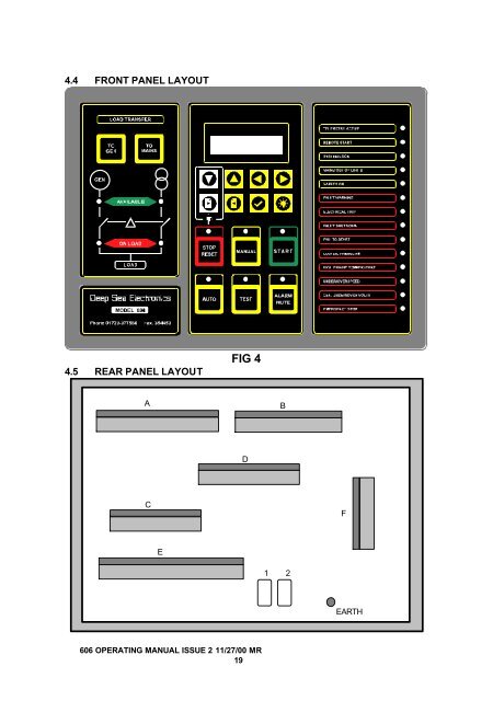
4.4 FRONT PANEL LAYOUT4.5 REAR PANEL LAYOUTFIG 4ABDCFE1 2EARTH606 OPERATING MANUAL ISSUE 2 11/27/00 MR19
- Page 1 and 2: Deep Sea Electronics PlcMODEL 606OP
- Page 3 and 4: 9. TYPICAL WIRING DIAGRAM..........
- Page 5 and 6: 1. OPERATION1.1 CONTROLControl of t
- Page 7 and 8: attempts to start have been complet
- Page 9 and 10: BATTERY HIGH VOLTAGE, if the module
- Page 11 and 12: AUXILIARY INPUTS, if an auxiliary i
- Page 13 and 14: NOTE:- If the following screen is d
- Page 15 and 16: This LED indicates that the module
- Page 17: i.e.:-Display shows:-EMERGENCY STOP
- Page 21 and 22: 29 Output 6 Normally open 0.5mm “
- Page 23 and 24: PLUG “E” 20 WAYPIN DESCRIPTION
- Page 25 and 26: 5.2 CONNECTOR FUNCTION DETAILSThe f
- Page 27 and 28: PLUG “E” 20 WAYPIN DESCRIPTIONN
- Page 29 and 30: 6. SPECIFICATIONDC Supply8.0 to 35
- Page 31 and 32: 8. FAULT FINDINGSYMPTOMPOSSIBLE REM
- Page 33: 10. APPENDIX606 OPERATING MANUAL IS
4.4 FRONT PANEL LAYOUT4.5 REAR PANEL LAYOUTFIG 4ABDCFE1 2EARTH606 OPERATING MANUAL ISSUE 2 11/27/00 MR19


