Télécharger PDF - Paul Forrer AG
Télécharger PDF - Paul Forrer AG Télécharger PDF - Paul Forrer AG
Assembly instructionsMontageanleitung37° flare flangesBördelflansche 37°Instructions de montageBrides d’évasement 37°C6. Minimum length of straight tubeend in tube bends and minimumstraight tube length.(see table)6. Mindestlänge für geradesRohrende bei Rohrbogen undminimale gerade Rohrlänge.(siehe Tabelle)6. Longueur minimale de l’extrémitédu tube droit dans un cintragede tube et longueur minimale detube en ligne droit.(voir tableau)7. Insert the centre unit inthe flangeMake sure the captive seals fit correctly.Fit the centre unit into the flaredtube, centring element first. Slide theflange over the centre unit. The centringelement does not serve to securethe centre unit in the tube!7. Zwischenring in FlanscheinlegenAuf ordnungsgemäßen Sitz der Weichdichtungenist zu achten. Zwischenringmit der Zentrierung voran in das aufgebördelteRohr legen. Flansch überZwischenring schieben. Die Zentrierungdient nicht zur Befestigungdes Zwischenringes im Rohr!7. Placer le cône intermédiairedans la brideOn veillera à ce que les joints moussoient correctement ajustés. Engagerle cône intermédiaire précédé du dispositifde centrage dans le tube évasé.Glisser la bride sur le cône intermédiaire.Le dispositif de centrage ne sertpas à fixer le cône intermédiaire dansle tube!8. Montage des visEngager 4 vis - vis hexagonales ouvis à six pans creux - dans les trousdébouchants prévus à cet effet.Vis à six pans creux (DIN DIN EN ISO4762) - Vis hexagonale (DIN EN ISO4014) -8. Fit the screwsInsert 4 screws - hexagon head orhexagon socket screws - in thethrough-holes provided for this purpose.Hexagon socket screw (DIN EN ISO4762) - Hexagon head screw(DIN EN ISO 4014) -8. Schrauben montieren4 Schrauben - Sechskant- oder Innensechskantschrauben- in die dafür vorgesehenenDurchgangslöcher stecken.Innensechskantschraube (DIN EN ISO4762) - Sechskantschraube(DIN EN ISO 4014) -9. Fit the flangePlace the flange on the connectingpoint. (When connecting two tubes,bring the two flanges into contact).Screw the screws into the threads byhand.9. Flansch anbringenFlansch auf die Anschlußstelle auflegen.(Bei Verbindung zweier Rohre beideFlansche gegeneinander auf Anlagebringen). Schrauben in Einschraubgewindemit der Hand eindrehen.9. Montage de la brideAppliquer la bride sur le point de jonction.(Pour un raccord de deux tubes,mettre les deux brides en appui l'unecontre l'autre). Procéder au serragemanuel des vis dans les trous taraudés.10. Tighten the screwsThe screws must be tightened accordingto torque (see below). Path-basedtightening is not permissible!Tighten the screws in cross-overfashion (1-2-3-4) and in several torquesteps until the maximum torque isreached!10. Schrauben anziehenSchrauben müssen nach Drehmoment(siehe unten) angezogen werden. Einedrehwegbezogene Montage ist nichtzulässig! Schrauben in mehreren Drehmomentstufenüber Kreuz (1-2-3-4) anziehen,bis max. Drehmoment erreicht ist!Achtung! Abweichende Drehmomentereduzieren die Nenndruckleistung unddie Lebensdauer der Verbindung. Leckagensind die Folge.10. Serrage des visLes vis doivent être serrées enappliquant un couple défini (voirci-dessous). Un montage par nombrede tours n'est pas admis! Serrer lesvis en diagonale et en plusieurs étapes(1-2-3-4) jusqu'à ce que le couplemaximal soit atteint!FlangeFlanschBride3000 PSI[“]ScrewSchraubeVisFlangeFlanschBride6000 PSI[“]ScrewSchraubeVisTorque M for screw 8.8Drehmoment M für Schraube 8.8Couple M pour vis 8.8(Nm)1/23/411 1/41 1/22M8 x 30M10 x 35M10 x 35M10 x 40M12 x 40M12 x 451/23/41M8 x 30M10 x 35M12 x 452553951 1/41 1/22M14 x 55M16 x 60M20 x 60150220390For screws having a strength of 8.8, the safetyfactor is 2.5.Bei Schrauben der Festigkeit 8.8 besteht eineSicherheit von 2,5Pour les vis ayant une résistance de 8.8, lecoefficient de sécurité est de 2,5.C56 EATON Walterscheid Fluid Conveyance Products E-MEFI-MC001-M1 03/2007
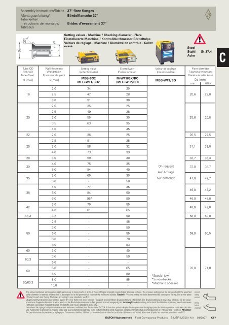
Assembly instructions/TablesMontageanleitung/TabellenteilInstructions de montage/Tableaux37° flare flangesBördelflansche 37°Brides d’évasement 37°Setting values - Machine / Checking diameter - FlareEinstellwerte Maschine / Kontrolldurchmesser BördeltulpeValeurs de réglage - Machine / Diamètre de contrôle - ColletévaséSteelStahl St 37.4AcierCTube ODRohr-ADTube Ø ext.d [mm]Wall thicknessWandstärkeEpaisseur de parois [mm]Setting value(potentiometer)MEG-BO2MEG-WF1/BO2Einstellwert(Potentiometer)M-WF385X/BO(MEG-WF2/BO)Valeur de réglage(potentiomètre)MEG-WF3/BOFlare diameterTulpendurchmesserDiamètre du collet évaséDa [mm]min max2,03420162,5472820,622,03,051302,035252,54928203,0553025,626,83,563354,0-45222,0362526,527,52,55135253,0583231,133,04,07339283,0593032,733,330354,05,03,05,0758465-35403050On requestAuf AnfrageSur demande37,041,838,742,7384,05,07784355046,047,26,095*5046,048,0423,04,07081556548,849,848,33,2-5058,059,02,5-483,0-50505,0-5559,060,56,0-708,0-83603,0-4060,33,65,6--50-6060/60,35,06,08,010,0----658095-*Special jaw*Sonderbacke*Mâchoire spéciale70,071,0The above-mentioned setting values apply exclusively to tubes made of St 37.4. Tubes of higher strength require higher pressure settings. The pressure setting must be increased until the specifiedcollar diameter is reached and the flare is developed to its full geometrical shape at the inside and outside. Caution! Pressure setting not to be determined by subsequent flaring. Use a new pieceof tube for each test flaring. Materials according to new standards see B12.Obige Einstellwerte gelten nur für Rohr aus St 37.4. Für Rohre mit einer höheren Festigkeit ist eine höhere Druckeinstellung erforderlich. Die Druckeinstellung ist soweit zu erhöhen, bis der vorgeschriebeneKragendurchmesser erreicht wird und die Bördeltulpe innen und außen geometrisch voll ausgeprägt ist. Achtung! Druckeinstellung nicht durch Nachbördeln ermitteln, jeweils ein neuesRohrstück verwenden (Probebördelung). Werkstoffe nach neuen Standards siehe B12.Les valeurs de réglage indiquées ci-dessus sont seulement valables pour des tubes en St 37.4. Il faut donc prévoir de plus hautes pressions de réglage pour des tubes ayant une résistance plus élevée.Augmenter la pression de réglage jusqu’à ce que le diamètre prescrit du collet soit atteint et le collet évasé soit complètement effectué géométriquement à l’intérieur et à l’extérieur. Attention!Ne pas déterminer la pression de réglage par l’évasement ultérieur. Utiliser un nouveau bout de tube le cas échéant (évasement d’essai). Materiaux d’après les nouveaux standards voir B12.correctrichtigcorrectwrongfalschincorrectEATON Walterscheid Fluid Conveyance Products E-MEFI-MC001-M1 03/2007 C57
- Page 82 and 83: CTurning-angle-controlled assembly
- Page 84 and 85: Assembly instructionsMontageanleitu
- Page 86 and 87: Assembly instructionsMontageanleitu
- Page 88 and 89: CAssembly instructionsMontageanleit
- Page 90 and 91: Assembly instructionsMontageanleitu
- Page 92 and 93: Assembly instructionsMontageanleitu
- Page 94 and 95: Assembly instructionsMontageanleitu
- Page 96 and 97: WALRingCAssembly instructionsMontag
- Page 98 and 99: Assembly instructionsMontageanleitu
- Page 100 and 101: Assembly instructionsMontageanleitu
- Page 102 and 103: Assembly instructionsMontageanleitu
- Page 104 and 105: Assembly instructionsMontageanleitu
- Page 106 and 107: +CAssembly instructionsMontageanlei
- Page 108 and 109: Assembly instructionsMontageanleitu
- Page 110 and 111: Assembly instructions/TablesMontage
- Page 112 and 113: +CAssembly instructionsMontageanlei
- Page 114 and 115: Assembly instructionsMontageanleitu
- Page 116 and 117: Assembly instructions/TablesMontage
- Page 118 and 119: +-MCAssembly instructionsMontageanl
- Page 120 and 121: Assembly instructionsMontageanleitu
- Page 122 and 123: CAssembly instructionsMontageanleit
- Page 124 and 125: Assembly instructionsMontageanleitu
- Page 126 and 127: Assembly instructions/TablesMontage
- Page 128 and 129: Assembly instructions/TablesMontage
- Page 130 and 131: CAssembly instructionsMontageanleit
- Page 134 and 135: Assembly instructions/TablesMontage
- Page 136 and 137: Assembly instructions/TablesMontage
- Page 138 and 139: CAssembly instructionsMontageanleit
- Page 140 and 141: Assembly instructionsMontageanleitu
- Page 142 and 143: Assembly instructionsMontageanleitu
- Page 144 and 145: Instructions for tube bending (6-18
- Page 146 and 147: Instructions for tube bending (Tube
- Page 148 and 149: Instructions for tube bending (Tube
- Page 150 and 151: Assembly instructionsMontageanleitu
- Page 152 and 153: Nuts and rings for profile ring tub
- Page 154 and 155: Nuts and rings for WALFORM tube fit
- Page 156 and 157: Connecting parts for flare tube fit
- Page 158 and 159: Connecting parts for flare tube fit
- Page 160 and 161: DD10 EATON Walterscheid Fluid Conve
- Page 162 and 163: Male stud coupling (body only)Gerad
- Page 164 and 165: Male stud coupling (body only)Gerad
- Page 166 and 167: Male stud coupling (body only)Gerad
- Page 168 and 169: Male stud coupling (body only)Gerad
- Page 170 and 171: Male stud elbow (body only)Winkel-E
- Page 172 and 173: Straight coupling (body only)Gerade
- Page 174 and 175: Equal elbow (body only)Winkel-Stutz
- Page 176 and 177: Reducing Tee (body only)T-Reduziers
- Page 178 and 179: Bulkhead coupling (body only)Gerade
- Page 180 and 181: Weldable stud (body only)Anschweiß
Assembly instructions/TablesMontageanleitung/TabellenteilInstructions de montage/Tableaux37° flare flangesBördelflansche 37°Brides d’évasement 37°Setting values - Machine / Checking diameter - FlareEinstellwerte Maschine / Kontrolldurchmesser BördeltulpeValeurs de réglage - Machine / Diamètre de contrôle - ColletévaséSteelStahl St 37.4AcierCTube ODRohr-ADTube Ø ext.d [mm]Wall thicknessWandstärkeEpaisseur de parois [mm]Setting value(potentiometer)MEG-BO2MEG-WF1/BO2Einstellwert(Potentiometer)M-WF385X/BO(MEG-WF2/BO)Valeur de réglage(potentiomètre)MEG-WF3/BOFlare diameterTulpendurchmesserDiamètre du collet évaséDa [mm]min max2,03420162,5472820,622,03,051302,035252,54928203,0553025,626,83,563354,0-45222,0362526,527,52,55135253,0583231,133,04,07339283,0593032,733,330354,05,03,05,0758465-35403050On requestAuf AnfrageSur demande37,041,838,742,7384,05,07784355046,047,26,095*5046,048,0423,04,07081556548,849,848,33,2-5058,059,02,5-483,0-50505,0-5559,060,56,0-708,0-83603,0-4060,33,65,6--50-6060/60,35,06,08,010,0----658095-*Special jaw*Sonderbacke*Mâchoire spéciale70,071,0The above-mentioned setting values apply exclusively to tubes made of St 37.4. Tubes of higher strength require higher pressure settings. The pressure setting must be increased until the specifiedcollar diameter is reached and the flare is developed to its full geometrical shape at the inside and outside. Caution! Pressure setting not to be determined by subsequent flaring. Use a new pieceof tube for each test flaring. Materials according to new standards see B12.Obige Einstellwerte gelten nur für Rohr aus St 37.4. Für Rohre mit einer höheren Festigkeit ist eine höhere Druckeinstellung erforderlich. Die Druckeinstellung ist soweit zu erhöhen, bis der vorgeschriebeneKragendurchmesser erreicht wird und die Bördeltulpe innen und außen geometrisch voll ausgeprägt ist. Achtung! Druckeinstellung nicht durch Nachbördeln ermitteln, jeweils ein neuesRohrstück verwenden (Probebördelung). Werkstoffe nach neuen Standards siehe B12.Les valeurs de réglage indiquées ci-dessus sont seulement valables pour des tubes en St 37.4. Il faut donc prévoir de plus hautes pressions de réglage pour des tubes ayant une résistance plus élevée.Augmenter la pression de réglage jusqu’à ce que le diamètre prescrit du collet soit atteint et le collet évasé soit complètement effectué géométriquement à l’intérieur et à l’extérieur. Attention!Ne pas déterminer la pression de réglage par l’évasement ultérieur. Utiliser un nouveau bout de tube le cas échéant (évasement d’essai). Materiaux d’après les nouveaux standards voir B12.correctrichtigcorrectwrongfalschincorrectEATON Walterscheid Fluid Conveyance Products E-MEFI-MC001-M1 03/2007 C57


