HS-1000 User's Manual
HS-1000 User's Manual
HS-1000 User's Manual
- No tags were found...

Create successful ePaper yourself
Turn your PDF publications into a flip-book with our unique Google optimized e-Paper software.
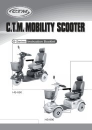
C.T.M. Mini Power Chair<strong>HS</strong>-<strong>1000</strong> <strong>User's</strong> <strong>Manual</strong>
<strong>HS</strong>-<strong>1000</strong><strong>User's</strong> <strong>Manual</strong>TABLE OF CONTENTSINTRODUCTION---------------------------------------------------------1IMPORTANT PRECAUTIONS------------------------------------------2ELECTROMAGNETIC INTERFERENCE AND WARNINGS-------3IDENTIFICATION OF PARTS------------------------------------------5OPERATING YOUR POWER CHAIR---------------------------------8DISASSEMBLING / RE-ASSEMBLING YOUR POWER CHAIR-11INSTALLATION OF BATTERIES-------------------------------------12CHARGING THE BATTERIES----------------------------------------14CARE AND MAINTENANCE------------------------------------------16TROUBLESHOOTING-------------------------------------------------18TECHNICAL SPECIFICATIONS --------------------------------------20
<strong>HS</strong>-<strong>1000</strong><strong>User's</strong> <strong>Manual</strong>3.Long-range transmitters and transceivers such as commercial broadcast transmitters(radio and TV broadcast antenna towers) and amateur (HAM) radios.Other types of hand-held devices, such as cordless phones, laptop computers,AM/FM radios, TV sets, CD players, and cassette players, and small appliances,such as electric shavers and hair dryers, so far as we know, are not likely tocause EMI problems to your motorized scooter.Power Chair Electromagnetic InterferenceBecause EM energy rapidly becomes more intense as one moves closer to the transmittingantenna (source), the EM fields from hand-held radio wave sources (transceivers) are ofspecial concern. It is possible to unintentionally bring high levels of EM energy very closeto the power chair control system while using these devices. This can affect power chairmovement and braking. Therefore, the warnings listed below are recommended to preventpossible interference with the control system of the power chair.WarningsElectromagnetic interference (EMI) from sources such as radio and TV stations, amateurradio (HAM) transmitters, two-way radios, and cellular phones can affect the power chair.Following the warnings listed below should reduce the chance of unintended brake releaseor power chair movement, which could result in serious injury.1.Do not operate hand-held transceivers (transmitters-receivers), such as citizens band(CB) radios, or turn ON personal communication devices, such as cellular phones,while the power chair is turned ON;2.Be aware of nearby transmitters, such as radio or TV stations, and try to avoid comingclose to them;3.If unintended movement or brake release occurs, turn the power chair OFF as soonas it is safe;4.Be aware that adding accessories or components, or modifying the power chair, maymake it more susceptible to EMI; and5.Report all incidents of unintended movement or brake release to the distributor listedon the inside front cover of this manual. Note whether there is a source of EMI nearby.Important Information1.20 volts per meter (V/m) is a generally achievable and useful immunity level against EMI(as of May 1994). The higher the level, the greater the protection.2.The immunity level of this product is 20 V/m.4
<strong>HS</strong>-<strong>1000</strong><strong>User's</strong> <strong>Manual</strong>IDENTIFICATION OF PARTSBefore attempting to drive this power chair on your own, it is important that you familiarizewith controls and how to operate.Width AdjustableArmrests18" Mid-Back Swivel Seatw/ Adj. Headrest & Seat BeltExtendedFootplatewith 3-AngleAdjustmentZero Effort SingleFree Wheel LeverFlat Free TiresFigure 1 - <strong>HS</strong>-<strong>1000</strong> Power Chair Front ViewSpeed Control ButtonSelf DiagnosticWarning Lights &Battery GaugeArm WidthAdjustmentThumbscrewsRear BagArm HeightAdjustmentThumbscrewsJoystickOn/OffButtonChargingPortCiricuitBreakerChargingIndicator/AmmeterHornRear ReflectorsFigure 2 - <strong>HS</strong>-<strong>1000</strong> JoystickFigure 3 - <strong>HS</strong>-<strong>1000</strong> Power Chair Rear View5
<strong>HS</strong>-<strong>1000</strong><strong>User's</strong> <strong>Manual</strong>JOYSTICKSpeed Dial KnobBy turning knob clockwise, you could increase speed. Turning knob counterclockwisewill decrease speed.Self Diagnostic Warning LightsFlashing of lights indicates there is a problem within power chair. See page 18 for moreinformation.Battery GaugeThere are six LED lights on joystick. When all LED lights are on, batteries are fullycharged; The Battery Gauge is used to indicate power on and provides an estimateof the remaining battery capacity.Any green LEDs lit indicate well charged batteries.If only amber and red LEDs are lit, the batteries are moderately charged. Rechargebefore undertaking a long trip.If only red LEDs are lit, the batteries are running out of charge. Recharge as soon aspossible.Swing Away BracketThe joystick is able to extend and retract. With joystick retracted, this enables you topull up to any table.ARMRESTFigure 4Armrest width Adjustment ThumbscrewsLoosen two thumbscrews to adjust armrest width; tighten again to lock in desiredposition.Figure 56
<strong>HS</strong>-<strong>1000</strong><strong>User's</strong> <strong>Manual</strong>FOOTPLATEFootplateThe footplate can be adjusted according to your specific needs. It can be adjustedvertically or horizontally. To adjust footplate, loosen screw (A) and arrange height todesired position, then, tightened screw (A) to secure plate in place.(A)POWER BASEFigure 6Free-Wheeling LeverWhen lever is in N (Neutral) position, power chair can be moved manually.When lever is in D (Drive) position, power chair can be driven. Normal position is D.Figure 7Circuit BreakerThis is to protect your power chair from overloaded current within the electrical parts.If power chair suddenly stops, push circuit breaker (A) back in will help resolve thisproblem.Charging portWhen charging your power chair, use power cordprovided. To correctly charge your power chair, connectone end to power chair (B) and the other end to awall outlet. See Charging the Batteries, page 14 forfurther instructions.7Figure 8
<strong>HS</strong>-<strong>1000</strong><strong>User's</strong> <strong>Manual</strong>OPERATING YOUR SCOOTERBefore beginning your journey with your new power chair, make sure power chair is ona level surface and clear of any obstacle. Although your power chair is able to climb slopes,it is safer to practice on a leveled surface.1.Before operating with your power chair, check the following:free-wheeling lever is on D.speed dial is at the lowest speed (fully turned counterclockwise).2.Sit on chair and fasten seatbelt.Figure 93.When power is turned on, all battery gauge LED lights should be lit lighting. The selfdiagnosticwarning lights should not be blinking.4.While resting your arm on armrests, joystick should be within reach. By pushing joystickslightly forward, power chair will move forward slowly, and pushing joystick fully forward,chair will move at normal speed. And adjusting speed dial will also decrease or increasespeed. Also, with joystick, you are able to turn chair in 360 o . When joystick is let go andback in center position, chair will stop.Figure 105.Practice driving where there is no obstacle. Start at slowest speed and move forwardand backward; make some turns. As you get more comfortable, you can increase thespeed by turning speed dial knob clockwise.8
<strong>HS</strong>-<strong>1000</strong><strong>User's</strong> <strong>Manual</strong>6.When the Battery Gauge is lighting in only few sections, you should plan to rechargethe batteries very soon.7.If power chair suddenly stops, and does not function, locate circuit breaker at the rearof power chair, then push it in and try driving again.Figure 118.When you are finished riding, turn power off before getting out. For safety it isrecommended you lift armrest first and get out from side.Release knob (D) to adjust to desired height then tighten knob (D).DDFigure 12While standing up, avoid stepping on footplate as it may cause injury.9.The batteries should be charged as soon as possible after each ride.See CHARGING THE BATTERIES on page 14.Keep in mind these rulesUse your power chair only where it is safe for walking.Drive in low speed when reversing, riding downhill on ramp or curb or on uneven surface.9
<strong>HS</strong>-<strong>1000</strong><strong>User's</strong> <strong>Manual</strong>Other Operating InformationHill climbing : You may need to use a higher speed. For a higher speed, turn speed dialclockwise.Down slopes : Proceed with dawnward slope slowly, and turn speed dial counterclockwise.This enables good control when speed is set in slower motion. However,your power chair will not self accelerate down hills due to. automaticbraking, taking effect should you attempt to drive too fast.Curb climbing : Approach slowly from right angles to the curb. A direct approach isneeded. Do not attempt greater than a 2" curb.If Self-Diagnostic Warning Lights start to flash, identify problem from chart on page 18and take action.If power chair breaks down and must be moved, please follow below directions :1.Get off power chair.2.Push free-wheeling lever to N.3.Move power chair slowly to a safe location.4.Push free-wheeling lever back to D.10
<strong>HS</strong>-<strong>1000</strong><strong>User's</strong> <strong>Manual</strong>DISASSEMBLING / RE-ASSEMBLINGYOUR POWER CHAIRTaking apart your power chair enables you to save space when keeping it in storage orcarrying it along in your vehicle. Having power chair disassembled is easier than eversince no tools are required.Seat RemovalPlease follow instructions below to remove seat from power base.1.Unplug joystick cable at rear of power chair.(See Fig. 13)2.Bend chair back forward and press lock pins underneath front and along seat sides tounlock, then lift chair up to remove.(See Fig. 14)(B)Figure 13 Figure 14Body Shroud Removal3.Removing shroud also requires no tools.4.Make sure free-wheeling lever is set to D so motors are engaged. (See Fig. 15) Theshroud is held by Velcro and is easily removed by lifting up. (See Fig. 16)Figure 15 Figure 16Re-assembleTo re-assemble your power chair, you can repeat disassembly directions in reverse.11
<strong>HS</strong>-<strong>1000</strong><strong>User's</strong> <strong>Manual</strong>INSTALLATION OF BATTERIESPlease follow instructions below to install batteries.1.Refer to page 11 on "DISASSEMBLING / RE-ASSEMBLING YOUR POWER CHAIR"before installing batteries.2.Make sure free-wheeling lever is set to "D" to engage motors.3.Once the shrouds are removed, fasten Velcro straps that will hold batteries in place.(See Fig. 17)Figure 174.Locate nuts and bolts that fasten battery cables to battery and then put them aside.5.Install new batteries, facing each other.batteryredblackblackredbatteryFigure 18 Figure 196.Locate one side of cables and make sure wire, marked (+), is connected to the closestpositive (red) battery terminal (See Fig. 18). Next, secure wires with nuts and boltsprovided (See Fig. 19). And then use a 10 mm wrench to tighten hardware (See Fig. 20).7.On the same cable, connect wire, marked (-), to the closest negative (black) batteryterminal on another battery (See Fig. 18). Next, secure wires with nuts and bolts provided(See Fig. 19). And then use a 10 mm wrench to tighten hardware (See Fig. 20).Warning: DO NOT attach one set of cables to the SAME battery, as it will not functioncorrectly.12
<strong>HS</strong>-<strong>1000</strong><strong>User's</strong> <strong>Manual</strong>Figure 208.Follow steps 6 - 7 for another side of the cables. (See Fig. 21)Figure 219.Make sure battery cables are tight and use Velcro strap to secure batteries in place.(See Fig. 22)Figure 22The stickers on frame should match battery cables (negative and positive).10.Re-assemble shroud and seat once above is completed.(Refer to page 11," DISASSEMBLING / RE-ASSEMBLING YOUR POWER CHAIR"for guidance).13
<strong>HS</strong>-<strong>1000</strong><strong>User's</strong> <strong>Manual</strong>CHARGING THE BATTERIESYour C.T.M. power chair is equipped with two, service free 12V 36Ah rechargeablebatteries and one 24V/3A on-board charger. Batteries must be charged before usingpower chair for the first time and it is recommended to be charged up to 8 - 14 hoursafter each day's use. Be sure power switch is in OFF position and free-wheelinglever is in "D" position.1.Insert charger cord into charger output at rear of power chair.Figure 232.Plug the other end of power cord into a standard electrical wall outlet.3.The purpose of ammeter is to indicate how much capacity is needed to fully chargebatteries. Once charger is warmed up, the ammeter needle may move up to threeamps, or as low as zero amps, as a sign in charging.4.The ammeter needle will then vibrate on the zero once the batteries are fully charged.5.Once batteries are fully charged, please unplug power cord from wall outlet and powerchair. The power cord should be stored in a safe and dry area until next use.6.If charging your power chair for over 8 - 14 hours and it does not function, please check :fuse is not burned outpower chair is turned offcircuit breaker is pushed inif none of above is the problem, contact your authorized dealer.The time needed to recharge will vary depending on depletion of batteries.Charging for longer than necessary will not harm batteries. They cannotbe overcharged.Keep in mind these rulesFully charge batteries at least once a month; more if you use power chair regularly.Charge after each trip exceeding 3 kilometers / 1.86 miles.If storing your power chair for some time (one month or more) make sure batteriesare fully charged, and on returning, charge them again before using power chair.14
<strong>HS</strong>-<strong>1000</strong><strong>User's</strong> <strong>Manual</strong>Batteries will only give maximum performance after power chair has been used, andbatteries have been recharged up to 10 times.For safety, please follow guidelines below.1.DO NOT use charger if power cord is damaged.2.DO NOT use an extension cord when charging batteries. A risk of fire and/or electricshock could be encountered.3.DO NOT take charger apart, as this will void warranty.15
<strong>HS</strong>-<strong>1000</strong><strong>User's</strong> <strong>Manual</strong>CARE AND MAINTENANCETaking care of your power chair will keep it in top-notch condition. It is recommendedthat you have your dealer to provide a thorough inspection and servicing. Regular cleaningwill reveal loose or worn parts and enhance the smooth operation of your powered scooter.Routine maintenance will extend the life and efficiency of your power scooter. Here arefew maintenance guidelines:BODY SHROUD:If your power chair is dirty, use a damp or lightly soapy cloth to wipe it down. Do not userunning water to wash or rinse power chair in order to protect electrical parts. Polishwith an automotive liquid polish.SEAT AND ARMRESTS:The seat material used by C.T.M. is of high quality and will remain in good condition formany years if treated responsibly. Using a damp cloth helps clean the upholstery greatly.Please note that using power chair outdoors could lead to sun damage to upholsterymaterial, and normal wearing and tearing is not covered under warranty.SEAT BELT:A damp cloth with mild soapsuds should only be used to clean seat belts. Wipe seat beltsgently and remove residue. Do not use any chemical products to clean seat belts as fabricwill be weakened.An authorized dealer should handle all maintenance and repair associatingwith electronics, batteries, motor parts, and tires. Here are the guidelinesthat can be followed by authorized dealer.FLAT SPOT (for solid tires only):During storage period, a flat spot may occur to solid tires. Weather conditions and storageperiod determine the condition of flat spots. By driving power chair 20 to 30 minutes, flatspots could be eliminated.16
<strong>HS</strong>-<strong>1000</strong><strong>User's</strong> <strong>Manual</strong>TIRE PRESSURE (for air-filled tires only):The condition of tires and maintenance of specified tire pressures not only influencetire life, but also effect road safety to a very considerable extent. Incorrect pressure isoften a cause of tire problems and could result in an accident. The recommended tirepressure is 35 psi.TIRE TREAD:Inspect the tires frequently for any signs of damage, such as unusual wearing or insufficienttread depth. Tread depth should not be allowed to drop below 1 mm.ELECTRICAL CONNECTIONS:.Make sure battery terminals and all plug connectors are secured and firmly attached. Ifbattery terminals are corroded, please contact your dealer for replacement.HARDWARE:Check that all hardwares and are securely fastened. Replace any missing hardware bycontacting your dealer.Additional InformationSTORING:Also between uses, your power chair is best stored in a dry location at room temperature.17
<strong>HS</strong>-<strong>1000</strong><strong>User's</strong> <strong>Manual</strong>TROUBLESHOOTINGFlash codes indicate the nature of an abnormal condition directly from the SHARK lnformationGauge. Without the use of any servicing tools, the condition can be simply diagnosed.Flash Code1234567891011User FaultBattery FaultLeft Motor FaultRight Motor FaultLeft Park Brake FaultRight Park Brake FaultSHARK Remote FaultSHARK Power ModuleFaultSHARKCommunications FaultUnknown FaultIncompatible RemoteDescriptionPossible stall timeout or user error.Release the joystick to neutral and try again.Try charging the batteries.Batteries may require replacing.Check the batteries and cabling.Check the left motor, connections andcabling.Check the right motor, connections andcabling.Check the left park brake, connections andcabling.Check the right park brake, connections andcabling.Check the SHARK Communications Busconnections and wiring.Replace the Remote.Check SHARK connections and wiring.Replace the Power Module.Check Battery voltage is greater than 17V.Check SHARK Bus Cable.Replace the SHARK Power Module.Replace the SHARK Remote.Check all connections and wiring.Consult a service agent.The Remote is incompatible with the PowerModule.Ensure the brand of the Power Modulematches that of the Remote.18
<strong>HS</strong>-<strong>1000</strong><strong>User's</strong> <strong>Manual</strong>Other ProblemsPower chair will not move when power is turned on :1.Check Battery Gauge on joystick. All LED lights should be on.2.Check Self-Diagnostic Warning Light. It should be steady; if it is flashing, see thechart on page 18 for problem identification.3.Check all electrical connections to be sure they are tight.4.Make sure batteries are connected correctly. Refer to "Installation of Batteries" onpage 12.5.If none of above correct problem, contact your authorized dealer.If charging your scooter for over 14 hours and light on charger does not change to green,then contact your authorized dealer.19
<strong>HS</strong>-<strong>1000</strong><strong>User's</strong> <strong>Manual</strong>SPECIFICATIONOverall LengthOverall WidthOverall HeightWheels: FrontWheels: MiddleWheels: RearWeight w/ BatteriesMax. SpeedWeight CapacityGround ClearanceGrade ClimbableCurb ClimbingTurning RadiusBrakeSeat WidthDrive TrainBattery WeightMotor SizeTravel RangeBatteryChargerElectronicsSeat Type37.5"23.2"40.2"7"N/A10"176.8 lbs4 mph300 lbs2.4"8 degree1.6"31.7"Electro-Mechanical18"2-Motor Rear-Wheel Drive55 lbs420W 4600 r.p.m15.2 Miles(2) 12V . 36Ah3A On BoardSHARKMid-back Swivel Seat w/ Adj.Headrest & Seat Belt*Subject to change without notice.20