BASICS OF INTERFEROMETRY - CMI
BASICS OF INTERFEROMETRY - CMI
BASICS OF INTERFEROMETRY - CMI

Create successful ePaper yourself
Turn your PDF publications into a flip-book with our unique Google optimized e-Paper software.
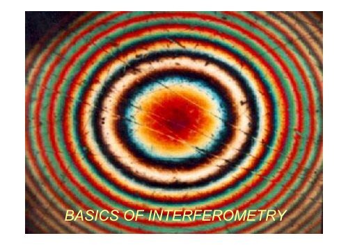
<strong>BASICS</strong> <strong>OF</strong> <strong>INTERFEROMETRY</strong>
CCD2
Interferometer
Typical InterferometerTest armCCDSampleReference armReferenceMirrorBeamsplitterOptical Path Difference (OPD)- difference in optical path lengths thatbeams travel in Reference and Test arms.•The expanded beamexiting from the lightsource is divided by aBeamsplitter into twobeams.•One beam is reflectedfrom the ReferenceMirror, and the other onefrom the Sample.•These two beams arerecombined by theBeamsplitter to interfere.•The imaging lensimages the interferogramonto the CCD camera.4
Tilt of one of Mirrors in InterferometerCCDSampleBeamsplitterReferenceMirrorIf one of the mirrors isslightly tilted,then the reflected beam(wavefront) also is tilted.If mirror and flatsample are perfectlyperpendicular, thenreflected wavefrontsare parallel.For two tilted and flat wavefronts, aninterferogram of straight, parallel, light anddark bands will be formed.5
Interferogram
Interferogram for Flat Wavefronts with TiltMultiple λ distancesbetween wavefronts,where λ is the wavelengthof the source.Interference betweentwo wavefronts isconstructive at thesemultiple λ points,destructive at others,forming aninterferogram.Fringe spacingcorresponds to λ pathdifference betweenwavefronts.Tested beam(wavefront)λ 2λ 3λReference beam (wavefront).4λTwo interferingwavefrontsIntensity profileof interferogram.Interferogram,(interference patternor fringe pattern)7
Change in Tilt Causes Change in Number of Fringes.NULL FRINGESWhen wavefronts are parallel thenthe fringes are nulled and almostuniform intensity is visible in thefield of view.Press EnterTestReferenceThe number and spacing of fringeschanges with tilt.8
Shape of fringes
Interferograms forSpherical SampleWhen one wavefront is spherical and the other is flat, and in additionditionthere is some tilt between interfering wavefronts, then the fringeswill be curved. When tilt is not present, the fringes are circular.10
Interferograms forSpherical SampleThe fringes can represent a concave wavefront instead convexwavefront as on previous slide.11
Typical Interferogram forSpherical SurfaceFringesPhase map13
Typical Interferogram forCylindrical SurfacesFringesPhase map14
Interference Microscope
Filter Bandwidthand Number of Fringes• Narrow bandwidth filter(3nm) (in PSI)• Medium bandwidth filter(40nm)• Wide bandwidth filter(300nm) - white light (inVSI)# of fringes ≈ 2λ/∆λ16
InterferenceDetector ArrayMicroscope DiagramDigitized IntensityDataFilters all but the redlight from white lightof halogen lampIlluminatorFilterBeamsplitterTranslatorLight SourceApertureStopFieldStopMicroscopeObjectiveMirauInterferometerSample17
Michelson Interferometer1.5X, 2.5X, 5Xsmall divergence of beamlong working distanceMicroscopeObjectiveWorkingdistanceBeamsplitterCubeReferenceMirrorNew workingdistanceSample18
Mirau InterferometerMicroscopeObjectiveReferenceBeamsplitterPlateSample19
Mirau Interferometer for Small Magnification?1.5X, 2.5X, 5Xsmall divergence of beamlong working distanceMicroscopeObjectiveReferenceLARGE central obscurationBeamsplitterPlateSample20
Surface Stats:Rq: 344.18 nmRa: 255.14 nmRt: 2.62 um22
Surface Stats:RMS: 7.23 umPV: 23.64 um29