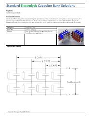
PowerBud White Paper
PowerBud White Paper
PowerBud White Paper

You also want an ePaper? Increase the reach of your titles
YUMPU automatically turns print PDFs into web optimized ePapers that Google loves.
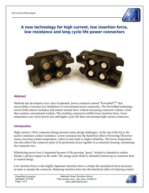
A new technology for high current, low insertion force,low resistance and long cycle life power connectorsAbstractMethode has developed a new class of patented power connector named “<strong>PowerBud</strong> TM ” thatsuccessfully overcomes key limitations of conventional power connectors. The <strong>PowerBud</strong> technologylowers both contact resistance and contact normal force without increasing connector volume, a featthat counters conventional wisdom. The resulting connectors exhibit lower insertion force, lowertemperature rise, lower power loss and higher cycle life than conventional high current connectors.IntroductionHigh current (>50A) connector design presents many design challenges. At the top of the list is theneed to minimize contact resistance. Lower resistance has the beneficial effect of lowering I 2 R powerlosses, lowering contact temperature, which in turn leads to higher reliability. The lower temperaturerise also allows the connector pairs to be positioned closer together in a connector housing, minimizingthe connector size.Minimizing power loss is important because of the growing “green” initiatives intended to reducehuman’s adverse impact on the earth. The energy used which is ultimately burned up as connector heatis wasted energy.Low insertion force is also highly important. Insertion force is simply the mechanical force necessaryto mate or unmate the connector. Reducing insertion force has the beneficial effect of reducing contact<strong>PowerBud</strong> connectorReleased 9/17/09Page 1 of 9Methode Power Solutions Group1750 Junction Ave., San Jose, CA 95112www.cablecotech.com
surface wear, a major contributing cause of connector failure. Previous efforts concentrated almostentirely on developing improved contact surface coatings and materials. Other design efforts modifiedthe pin shape to minimize the insertion force.This paper discusses the design tradeoffs and innovative methods to optimize current rating, contactresistance and insertion force, and how those tradeoffs led to the development of an innovative newpower connector technology.Conventional connector challengesManufacturers finely polish and plate mating contactsurfaces in order to increase contact surface area, leadingto a general misconception that current flows through theentire mated surface area. However, the actual percentageof that area which actually makes contact with the matingconnector is very small. Fig. 1 shows that a polishedgold-plated mating surface, viewed on a microscopiclevel, consists of peaks and valleys called asperities.Electrical current is concentrated and passes through theasperities which are in actual contact.Manufacturers have adapted to the limited amount ofcontact area using different methods to maintain low contact resistance, includingFigure 1: Surface topography showingasperities on a polished, gold-plated berylliumcoppercontact surface1. Increasing the size of the mating contacts, which yields many more microscopic points ofcontact. The result is a larger, more costly connector.2. Increasing the “normal force” pressing the two mating surfaces together, which slightlydeforms the asperities thereby increasing contact surface area. The result is a connector withhigh friction force that is more difficult to mate, or an expensive connector mechanism toprovide the additional force after mating.3. Using a manufacturing process to reduce the surface asperitiesThe need to mechanically force the mating surfaces together has led to many design compromises.Since copper is one of the very best reasonably-priced electrical conductors (excluding gold, silver andother exotic materials), it would be a good choice for the mating parts of the connector. However,copper has poor mechanical spring properties. If both mating surfaces were pure copper, the connectorwould also require an additional spring to maintain copper-to-copper contact. In the connector world,that yields an expensive product.A more practical solution is to choose a material with both spring and conductive qualities such asberyllium copper or tin copper. While less conductive than pure copper, these copper alloys are easilyfabricated into a part that serves both as spring and conductor. This solution is widely used today inlow cost connectors.<strong>PowerBud</strong> connectorReleased 9/17/09Page 2 of 9Methode Power Solutions Group1750 Junction Ave., San Jose, CA 95112www.cablecotech.com
Microscopic look at plated contactsThe actual points of contact between matedsurfaces can have a relatively high resistanceand therefore a relatively high voltage drop.Each of these points of contact has a finiteresistance.One way to minimize the overall contactresistance is to have many points of contact.By placing lots of contacts “in parallel”,junction resistance is reduced.Figure 2. First Contact x/z cross-sectional view takenacross Au contact interface showing potential valuesrepresented as gray scale and height.Tribotek technology developed by Massachusetts Institute of Technology researchersMethode’s original WovenBud was developed by a MIT professor and graduate students investigatingtribology, the science and technology of interacting surfaces in relative motion. It includes the studyand application of the principles of friction, lubrication and wear. The company name Tribotekoriginates from the word tribology.The researchers developed a prototype powerconnector with superior qualities compared toconventional, commercial power connectors.The Tribotek connector, as it was later called,had very low contact resistance as well asvery low insertion force, without acommensurate connector volume increase.Figure 3: Illustration of Tribotek connectorbasic elements showing pure copper wirewrapped around Kevlar tensioning fiber andheld in contact to a copper mating pin.Tribotek connector performance is based onmaximizing the number of discrete points ofcontact rather than attempting to increase thecontact surface area or polish the matingsurfaces to a finer degree. Furthermore, theconductors are pure copper to minimizeresistance. Tribotek fabricated a socket-styleconnector by weaving pure copper wirearound a Kevlar non-elastic cord held undertension to produce a connector with manypoints of contact around the circumference ofthe mating pin.<strong>PowerBud</strong> connectorReleased 9/17/09Page 3 of 9Methode Power Solutions Group1750 Junction Ave., San Jose, CA 95112www.cablecotech.com
The connector technology handles almost 500A with very low voltage drop and very low insertionforce. Because the fabrication of this connector is labor-intensive, it tends to be used for high valueapplications.Contact Termination BodyMetal springConducting wireTensioning Fiber (Kevlar)Mating pinFigure 4: Photograph of practical Tribotekstyleconnector showing wound copper wire,Kevlar cord and tensioning spring.How the WovenBud lowers contactresistanceA single conductor weave has at least fourpoints of contact and possibly many moredepending on the number of asperities oneach mating surface. Each electrical pathcan be modeled as a resistor in a matrix,which results in four parallel paths. Inaddition, the resistance contributed by thecopper wire itself is 4 times lower than themore frequently used beryllium copper.The Kevlar spring need only provideenough force to assure surface intimacy.The resulting lower insertion force meansless sliding resistance to mate the contactand therefore less wear over time.Figure 5: Equivalent resistancemodel of a single weave. Figure6 (left): equivalent resistance ofmultiple weavesBy arranging all individual weaves in a circular assembly results inmassively parallel contact points, significantly lowering overall connectorresistance. Low contact resistance means less heat generated under highcurrent loads and less power loss.<strong>PowerBud</strong> connectorReleased 9/17/09Page 4 of 9Methode Power Solutions Group1750 Junction Ave., San Jose, CA 95112www.cablecotech.com
This design approach has yielded a new type ofconnector with exceptionally low contactresistance as well as very low insertion force. Theonly drawback to this approach is the cost ofassembly, which limits the use of this connector tohigh value applications.Methode develops the <strong>PowerBud</strong>technologyMethode acquired Tribotek in 2008 and continued todevelop the Tribotek connector. The result was the<strong>PowerBud</strong>, an evolution of the WovenBudtechnology. It embodies the same design approach –massively parallel points of contact – but using amechanical design that is adaptable to massproduction. The resulting connector has many of thesame electrical qualities of the WovenBud with alower production cost.Figure 7 (above): <strong>PowerBud</strong> mechanicalconstruction showing dual contact points on eachfinger. Figure 8 (below)photomicrograph of a<strong>PowerBud</strong> connector.The <strong>PowerBud</strong> uses two rows of conductors arrangedone over the other. Instead of using pure copper forcontacts, the <strong>PowerBud</strong> uses a proprietaryperformance-engineered copper alloy material that issubstantially better than the more commonly usedberyllium copper alloy. The conductors have a largercross-section than those on the WovenBud connectorto minimize resistance.The high performance copper alloy is easilyfabricated using automated processes. In addition,each copper alloy beam includes a slight indentationin the finger tip to create dual contact points, addingto the massively parallel contact points.The easily fabricated fingers are primarily responsiblefor lowering the cost of the connector compared tothe WovenBud (Tribotek) design with little sacrificein performance.<strong>PowerBud</strong> connectorReleased 9/17/09Page 5 of 9Methode Power Solutions Group1750 Junction Ave., San Jose, CA 95112www.cablecotech.com
This figure shows the relationshipsbetween three connectors with respectto contact resistance and insertionforce. Competitive connectors have ahigher contact resistance and higherinsertion force than either the<strong>PowerBud</strong> or WovenBud.<strong>PowerBud</strong> performancePow erBud vs. competition voltage drop, 6.4mm or equivalent pin35.030.025.020.0mV15.010.05.00.0140 160 180 200 220 240 260AmpsCompetitor Vdrop (mV)Pow erBud Vdrop (mV)<strong>PowerBud</strong> connectorReleased 9/17/09Page 6 of 9Methode Power Solutions Group1750 Junction Ave., San Jose, CA 95112www.cablecotech.com
Pow erBud vs. competition temp rise, 6.4mm or equivalent pin454035Centigrade degrees302520151050140 160 180 200 220 240 260AmpsCompetitor temp rise ºC Pow erBud temp rise ºC<strong>PowerBud</strong> vs. competition mating / unmating force, 9.1 mm pinMateUnmate<strong>PowerBud</strong> 4N (0.9 lb) 4N (0.9 lb)Competitor 21N (4.7 lb) 13N (3 lb)<strong>PowerBud</strong> vs. competition cycle life<strong>PowerBud</strong>Competitor10,000 cycles1,000 cycles est<strong>PowerBud</strong> connectorReleased 9/17/09Page 7 of 9Methode Power Solutions Group1750 Junction Ave., San Jose, CA 95112www.cablecotech.com
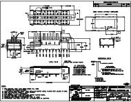
<strong>PowerBud</strong> versionsThe PQ panel connectors feature four <strong>PowerBud</strong> contactsin a molded thermal plastic housing designed for blindmateapplications. Each connector half floats undershoulder mounting hardware and self-aligns to the matingconnector half. This connector uses a 9.1mm pin rated at300A @ 400VAC per contact.The MQuad is similar to and slightly smaller than the PQpanel connector. MQuad panel connectors are alsodesigned for blind-mate applications. Each connector halffloats under shoulder mounting hardware and self-alignsto the mating connector half. Contact terminations can becrimp wire, wired lugs or busbar attached. The MQuad issmaller than the PQ, and uses a 6.4mm pin rated at 100A@ 600VAC per contact with a 30ºC temperature rise.The Slim Latch is designed for compact applications inwhich connector current must be optimized while limitingconnector volume. The Slim Latch connector includes anintegral locking mechanism, eliminating the need foradditional means to mechanically secure the connector. Ituses a 2.4mm pin designed for 10 AWG wire and is ratedat 50A @ 600VAC per contact.The embedded <strong>PowerBud</strong> connectors have knurledouter side walls allowing direct press-fit insertion intobusbars, printed circuits boards and FusionLugs TM .Installation or press-in is accomplished using any flatsurface and does not require any special tooling. Thecurrent rating is dependent on the physical size of the pinand the heat-sinking capability of the mounting medium.<strong>PowerBud</strong> connectorReleased 9/17/09Page 8 of 9Methode Power Solutions Group1750 Junction Ave., San Jose, CA 95112www.cablecotech.com
ConclusionThe <strong>PowerBud</strong> is a new class of power connector offering lower voltage drop resulting in lowertemperature rise and lower insertion force than competitive connectors and much less thanconventional connectors. The unique mechanical construction evolved from the Tribotek connector, apioneer design which delivers a quantum improvement in power connector performance.<strong>PowerBud</strong> allows more current to pass through a connector that occupies a small volume, potentiallyreducing package footprint. The lower voltage drop can eliminate the need for a local voltage regulatormodule. The lower temperature rise reduces system thermal load.The <strong>PowerBud</strong> is suitable for systems that require connectors capable of handling hundreds of amps ofcurrent. It is particularly suitable for systems that require the connector to be mated and unmatedfrequently.<strong>PowerBud</strong> connectorReleased 9/17/09Page 9 of 9Methode Power Solutions Group1750 Junction Ave., San Jose, CA 95112www.cablecotech.com