Multi-Camera Based Surveillance System - KPIT
Multi-Camera Based Surveillance System - KPIT
Multi-Camera Based Surveillance System - KPIT

Create successful ePaper yourself
Turn your PDF publications into a flip-book with our unique Google optimized e-Paper software.
<strong>Multi</strong>-<strong>Camera</strong> <strong>Based</strong> <strong>Surveillance</strong> <strong>System</strong>Reena Kumari Behera, Pallavi Kharade, Suresh Yerva, Pranali Dhane, Ankita Jain, and Krishnan KuttyCenter for Research in Engineering Sciences and Technology (CREST)<strong>KPIT</strong> Cummins Infosystems LimitedPune 411057, IndiaAbstract—In recent years, surveillance systems have gainedincreased importance in order to increase the safety andsecurity of people. These systems have applications in variousdomains like home or bank security, traffic monitoring,defense; and in public places like railway stations, malls,airports, etc. Our goal is to develop an intelligent real-timesurveillance system that can help in increasing the efficiency ofthe system. In order to cover a large area, we need to installmore number of cameras that leads to more number of videosthat are to be monitored simultaneously. This in turn increaseshuman intervention and makes it error prone. Therefore, it isof utmost importance to automate the complete system. In theproposed system, cameras are placed in such a way that thereis a significant overlap between the field of view of thecameras. This helps in establishing an association between thecameras. The proposed real time surveillance system detectsand tracks the objects in motion and provides automaticwarning in case of suspicious activities such as unidentifiedobject and restricted zone monitoring. The system providesdifferent views in different cameras, thereby helping inresolving the occlusion in a simple and novel way. Thealgorithm has been tested on a CPU platform (Intel dual corewith 4 GB RAM) with four wireless IP cameras (1.3 MPEDiMAX camera with night vision support) with a processingrate of 10 fps. This system can handle up to eight cameras on aGPU platform (NVIDIA GeForce GTX 480) with frame rate of25fps.Keywords- <strong>Multi</strong>-camera, surveillance, homography,handshaking, occlusion.I. INTRODUCTION<strong>Surveillance</strong> system helps to monitor a given area ofinterest. <strong>Multi</strong>ple cameras are used to cover a large area. Inorder to track objects successfully in multiple cameras, oneneeds to handshake among objects captured in multiplecameras. The key elements of our proposed surveillancesystem include change detection, tracking, cameracoordination, occlusion handling and suspicious activitymonitoring.Change detection is a basic module of any surveillancesystem. The detected changes can be considered asforeground objects by modeling the background. Generally,background subtraction and its variants are used to extractthe foreground objects from the video stream taken from astationary camera [1, 2]. However, detecting the foregroundobjects becomes hard when the background includesvariations due to light, shadows and insignificant periodicchanges of background objects (e.g. swaying trees). Bayesdecision framework is used to extract foreground objectsfrom a real-time complex video [3]. This method consumesmore memory owing to the number of parameters used,thereby increasing the processing time as compared toGaussian Mixture Model (GMM). GMM framework [4] canovercome these limitations. The value of each pixel ismodeled as a mixture of Gaussians. According to thepersistence and variance of each mixture of Gaussians, thepixel is determined whether it belongs to foreground orbackground.Once an object is detected, tracking is required toestimate its trajectory in the image plane. In other words, atracker assigns consistent labels to the tracked objects acrossdifferent frames of a video. Some of the algorithms used fortracking include detection of discontinuities using Laplacianand Gaussian filters; and are often implemented using asimple kernel. These algorithms are simple, but sensitive tonoise, and hard to generalize [5]. Fatih Porikli et al. havedescribed tracking using multiple kernels centered at the highmotion areas [6]. Other algorithms make use of patternrecognition, such as neural networks, maximum-likelihoodand support vector machines. The majority of patternrecognition algorithms require a set of training data to formthe decision boundary [7].Suspicious activity detection is an essential part ofeffective surveillance system. Real time surveillance systemcollects large amount of videos and it is important toautomate the system to extract useful information aboutdifferent types of suspicious behavior. Ismail Haritaoglu etal. [1] have described a system that monitors suspiciousactivities such as depositing an object, exchanging bags, orremoving an object etc.Benjamin et al. [8] presented an overview of a multicamera surveillance system that can automatically extractuseful information from a given scene. It also alerts the userif any of the tracked objects breaks certain defined rules.Xiaogang Wang [9] gives an overview of the recentadvances in the field of multi camera video surveillance. Itcompares the existing solutions and also describes theprevalent technical challenges.Steve Shafer et al. [10] have described prototypearchitecture and technologies for building intelligentenvironments that facilitate the unencumbered interaction ofpeople with other people, with computers and with devices.Kiosk [11] is a vision based human sensing applicationwhich uses color stereo tracking and graphical output tointeract with several users. The system can detect and trackthe arrival and departure of potential users in the vicinity ofthe kiosk and can identify individual users during multipersoninteraction. Kidrooms [12] is an indoor trackingsystem where multiple isolated objects can be tracked inreal-time.10.1109/WICT.2012.6409058 © 2012 IEEE
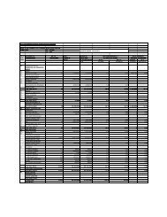
TABLE I.COMPARISON OF THE PROPOSED SYSTEM WITH PREVIOUS WORK IN TERMS OF COVERAGE AND FUNCTIONALITYArea Sensor <strong>Camera</strong> Detection People Tracking<strong>System</strong>Indoor(I)Outdoor(O)Color(C)Grayscale(G)Single (S)Stereo (O)<strong>Multi</strong>ple (M)Single Gaussian (S)Bimodal (B)Mixture of Gaussian(M)Single Isolated (S)<strong>Multi</strong>ple Isolated (M)<strong>Multi</strong>ple in Group (G)EasyLiving[10] I C M,O S MS.Kiosk[11] I C S,O S SKidsroom[12] I C M S MM.Mirror[13] I C O S MPfinder[14] I C S S STI [15] I G M S SSRI [16] I G M S SMIT [4] O C M M MCMU [17] O C M S MW 4 [1] O G S B M,GLOTS [18] O G S S MProposed Approach I,O C M M MDarrell et al. [13] presents a real time system for trackingpeople; stereo processing is used to isolate people from otherobjects and background. Color and face detection modulesare also included to make the system robust. Pfinder [14]works when there is only a single person in the field of viewof camera. Silhouettes are used to detect human body and 2Dcontour shape analysis is used to identify the head, hands andfeet locations. TI’s system [15] uses change detection torecognize moving objects. The detected objects are trackedusing first-order prediction and nearest neighbor matching.Events are recognized by applying predicates to the graphformed by linking corresponding objects in successiveframes. SRI’s system [16] uses stereo information forcontinuous detection and intensity image correlation fortracking. The system provides information for 3D detectionand tracking, even in the presence of crowded scenes,blurred objects, and large-scale changes. MIT’s system [4]uses GMM to model the background and tracks people inindoor environment, people and cars in outdoor environment,fish in a tank etc. CMU [17] uses temporal differencing todetect moving objects and these objects are classified ashuman, vehicle or background by using template matching.This system rejects background clutter and continuouslytracks intended objects despite occlusion and appearancechanges. Ismail Haritaoglu et al. [1] have explained a realtime visual surveillance system for detecting and trackingmultiple people and monitoring their activities in an outdoorenvironment. LOTS [18] suggested background subtractionfollowed by connected component labeling to detect multipleisolated moving bodies. It can detect people even in case ofcamouflage. The proposed approach uses multiple camerasto track multiple isolated people in indoor as well as outdoorenvironment.This paper presents a set of techniques integrated into alow-cost PC based real-time visual surveillance system, forsimultaneously tracking people, and monitoring theiractivities. The rest of the paper is organized as follows.Section II describes the system setup. Section III givesdetailed description of the methodology used in the proposedsystem. This is followed by conclusion and future work inSection IV and V.II.MULTI-CAMERA SETUPTable 1 shows the comparison of the proposed multicamerasurveillance system with the systems existing inliterature. In the proposed approach, cameras are set up insuch a way that there is a significant overlap between theirfield of view (FOV).In our experimental set up, a minimum of 30% overlap ismaintained. The cameras can be placed at different heightsand orientations. Fig. 1 gives an overview of the setup for theproposed multi-camera surveillance system.Figure 1. <strong>Multi</strong>-camera set upA. Association between camerasThe proposed system deals with multiple cameras. Eachcamera has its own local coordinate system. In order toestablish an association between the objects in differentcameras, the coordinate system of these cameras needs to beassociated.Any two camera views can be associated using anappropriate transformation matrix. In this paper,homography-based transformation is used for establishingthe association.Projective transformations or homographies have eightdegrees of freedom. The transform can be represented byX0 HX(1)Where, H HS HA HP , X represents the coordinatesin camera view 1 and X 0 represents the correspondingcoordinates in camera view 2. Here H S represents a similaritytransformation, H A represents an affinity and H P represents aprojective transformation [19].The Direct Linear Transform (DLT) algorithm is used tosolve the homography matrix. Consider two images for10.1109/WICT.2012.6409058 © 2012 IEEE
which homography matrix have to be calculated. Therelation between two corresponding pointsT( x y 1)andT( u v 1)in two images can be written as:u x cv Hy 1 1Where c is any non-zero constant andh1h2h3 H h4h5h6 h7h8h9Subtracting first and second rows from third row in (2)yields: h ( )1x h2y h3 h7x h8y h9 u 0 (4) h x h y h ( h x h y h ) 9v 0 (5)4 5 6 7 8Equations (4) and (5) can be written in matrix form as:A i h = 0 (6)WhereA x y 10 0 0 xu yu u i 0 0 0 x y 1 xv yv v And Th h1h2h3h4h5h6h7h8h9A minimum of four corresponding points is sufficient tosolve for the coefficients of the homography matrix. Sinceeach point correspondence provides two equations, fourcorrespondences are sufficient to solve for the eight degreesof freedom of H. In this paper, singular value decomposition(SVD) is used to solve the homography matrix.B. Field Of View(FoV) LinesIn order to establish the relation between differentcamera’s field of view (FOV), the FOV of a given camera ismarked in the overlapping FOV of other cameras. The FOVof a given camera can be represented by an area bounded bya maximum of four lines in any other camera’s FOV.Considering a setup of two cameras, the following stepsillustrate the methodology to obtain FOV lines using thehomography matrix. H 12 represents the homographytransformation from camera 1 to camera 2 and H 21 representsthe homography transformation from camera 2 to camera 1.The matrices H 12 and H 21 can be calculated as explained insection II-A.The FOV of a given camera can be defined using arectangular region as shown in Fig. 2. The FOV lines ofcamera 1 are denoted by L 11 , L 12 , L 13 , L 14 and for camera 2by L 21 , L 22 , L 23 , L 24 respectively. The projection of L 11 , L 12 ,L 13 , L 14 lines in camera 2’s FOV are denoted by L 11 ’, L 12 ’,L 13 ’, L 14 ’.Extracting FOV Lines:1. Consider the co-ordinates of the points on theboundary of camera 1 i.e., on lines L 11 , L 12 , L 13 , L 14as shown in Fig. 2.(2)(3)Figure 2.FOV lines2. Transform the boundary co-ordinates of camera 1using H 12 transformation matrix.3. The transformed co-ordinates result in the linesL 11 ’, L 12 ’ and L 13 ’. L 14 ’ is not represented becausethe transformed coordinates do not lie within thelimits of the size of the image.4. Repeat steps 1, 2 and 3 to obtain the FOV lines ofcamera 2 on camera 1.III.METHODOLOGYFig. 3 provides an overview of the proposed multicamerasurveillance system.A. Change DetectionThe change detection module detects and separates theforeground changes from the background in a given frame.A background model corresponding to each camera view isbuilt using the K-Gaussian mixture models (GMM) [4]. Inthe background model, recently observed values of eachpixel of gray image are retained in the form of mixture ofGaussians based on their weights (ω) and are arranged inascending order of the value of ω/σ, where σ is standarddeviation. Value of each pixel (X t ) of a frame at time ‘t’ ischecked against K-Gaussian mixture models. If matchfound, then its mean (µ t ) and variance (σ t 2 ) are updatedusing following equations:Where,(0, 0) (0, 0)2t ( 1) X(7)tt 1t12T (1 ) (X ) ( X ) (8)tt X , )(9)(t k kα is learning rate and η is Gaussian probability density.In addition, weights corresponding to K- Gaussiandistributions are updated using following equation: 1)(M )(10)k, t(k,t 1 k,tThe time taken to adapt a foreground object as abackground object depends on the learning rate (α). Thevalue of learning rate is taken depending on the scene onwhich GMM is to be applied. Morphological operations areperformed on foreground objects, which are obtainedttt10.1109/WICT.2012.6409058 © 2012 IEEE
through GMM. Finally, the objects are segmented usingconnected component labeling as explained in Fig. 4. Thesystem handles variations due to light and eliminatesshadows and insignificant periodic changes of backgroundobjects.Input from multiple camerasChange detection and object tracking to detectmoving objectsBhattacharya distance( u)( u)( D) p * q (11)mu12 2D/ 2 (1/ 2)* e(12)weightHere, p and q are histograms of current and previousstate of any given change respectively.2 = variance of previous state of a changeFor each change, weighted mean of centers of itscorresponding new probable states is considered as center ofits new state. Histogram of the new state is computed usingfollowing equation where α is the learning rate.histogram of new state [ * histogram of previous state] [(1 ) * histogram of new state]Handshaking between the camerasOcclusionHandlingUnauthorized Object IdentificationCheck for unauthorized objectDisplay warning if unauthorizedobject foundZone MonitoringAccept zone from userMonitor the selected zone anddisplay appropriate warningFigure 3. <strong>System</strong>-level block diagramB. TrackingA tracking algorithm is used to establish correspondencebetween the changes detected in consecutive frames. In thispaper, particle-filtering method with histogram as a featureis used to achieve correspondence [20]. The algorithmretains changes (i.e. blobs) of previous frame in the form ofa data structure called “state”. The elements of ‘State’ arehistogram, position, center, height, and width of a changedblob. For each change, using the particle filtering approach,we consider certain regions in the neighborhood as probablenew states. For instance, if there is only one change in theprevious frame with center (13, 21), height 10 and width 6then we can consider a region with center (12, 18), height 10and width 6 as the probable state. In the proposed approach,Bhattacharya distance measure is used to compute thesimilarity between the histogram of any given change in thecurrent and previous state.Figure 4. Change Detection and TrackingC. HandshakingIn multi-camera environment, an object might be in theFOV of one or more cameras. The identity of the objectneeds to be consistent across the cameras, which is achievedthrough handshaking. A particular point in camera 1 is inthe overlapping FOV of camera 2 if the homographytransformation of that point in camera 2 yields a co-ordinatewhich is within the size limits of the given image.Whenever, a new object enters the overlapping FOV of acamera, all the other cameras having overlapping FOVregion with the current camera are checked for handshaking.We have implemented two variants for handshaking asdescribed in section a) and b).10.1109/WICT.2012.6409058 © 2012 IEEE
Our Approach for handshaking:a) As shown in Fig. 5, the result of transformation ofobject 1’ in camera 2 is H(obj 1’) in camera 1. Object1 in camera 1 is nearest to H(obj 1’). Hence, object 1in camera 1 is the probable candidate to be associatedwith object 1’ in camera 2.b) The distance between the center of the object andFOV lines is used in this section [21]. Consider that an object enters the FOV of camera 2through line L 24 (as shown in Fig. 5). Thecorresponding line L 24 ’ of camera 1 should be takeninto consideration for further calculations. Consider the possible scenarios listed below:Single object entering the FOV:i. The perpendicular distance of the objects thatare in the overlapping zone of camera 1 and 2,in camera 1 from L 24 ’ i.e., D 1 and D 1 ’ iscalculated as shown in Fig. 5.ii. The object with the minimum perpendiculardistance is the probable candidate to behandshaked with the new object i.e., object 1’have to be handshaked with object 1 (Fig. 5).More than one object entering the FOV:i. If more than one object enters the FOV at thesame time, the perpendicular distances mightbe similar. In order to overcome this situation,an additional distance is calculated fromanother point on the FOV line.ii. If P 1 ’ is equal to P 1 (Fig. 5), the distance P 2 ’and P 2 are compared with distance D 2 ’ and D 2 .iii. P 2 ’ > P 2 and D 2 ’ > D 2 implies that object 1’and object 2’ have to be handshaked withobject 1 and object 2 respectively.Figure 5. FOV line based handshakingFig. 6 shows the output after performing handshaking.Figure 6. Result of handshakingD. Occlusion Detection and Handling:In real-time scenarios, where multiple objects are beingmonitored using surveillance systems, quite often overlap ofsome of these objects is observed. This is termed asocclusion. Consequently, there is loss of information ofoccluded objects. In order to prevent loss of information insuch scenarios, we need to detect and handle occlusion.Fig. 7(a) shows the situation before occlusion where twopersons have different identities. However, during occlusiontwo persons are detected as a single object with same identityas shown in Fig. 7(b).Occlusion can be detected by monitoring the differencebetween centers of any two objects in a frame usingfollowing equation:X differenceW2W2( 1 2 ) cx cx 12OccludingobjectOccludedobject(a)(b)Figure 7. (a) Before occlusion (b) Situation of occlusion(13)( H1 H2Y ) cy122 2cydifference (14)Where,W 1 , H 1 = width and height of first object respectively.W 2 , H 2 = width and height of second object respectively.( cx1 , cy1 ) = center of first object( cx2, cy2 ) = center of second objectIf X difference and Y difference are positive then we say thatocclusion is detected and objects’ information is stored. In anocclusion scenario, there are two types of objects as shownin Fig. 7(b) occluding object (the object which is clearlyvisible), occluded object (the object which is partly orcompletely invisible). Assume that the origin is at the top leftcorner of the image. The occluding object always has highervalue of y-coordinate than that of the occluded object in theimage (Because occluding object is near to the camera thanthe occluding object). Thereafter, percentage overlapbetween the two objects which are in occlusion is calculatedusing the following equation.XdifferenceYdifferencePercentage overlap (15)W 1 H 1If the percentage overlap is less than 50%, then theobjects are tracked separately otherwise those objects aretracked together considering them as a single object. Theobjects which are tracked together would be trackedseparately again when percentage overlap becomes less than50% using the information that we stored when occlusionwas detected for the first time. Fig. 8 shows the situation10.1109/WICT.2012.6409058 © 2012 IEEE
where occlusion is resolved and two persons get back thesame identity which they had before occlusion.Figure 8. Occlusion resolvedE. Suspicious activity monitoring:Merely tracking people continuously might not sufficein most of the surveillance systems. There might be somerestricted events that have to be prevented from happening.This can be achieved by defining the restricted events at thefirst place. In case any such event is detected, a suitableaudio/visual warning is issued.1) Unauthorized object detection:Whenever a person tries to leave a baggage/object, twoseparate objects are originated from a single object in theconsecutive frame.Person Awith bagPersonAFrame 2Figure 9. Splitting ConditionFig. 9 illustrates the condition of splitting that is used indetection of unauthorized baggage.The following steps illustrate the methodology:1. Detecting the splitting of a single object into twoobjects [22].2. Monitoring the split objects continuously todistinguish between the stationary object and theobject in motion.3. The stationary object is tagged as suspicious withthe identity of the object in motion.The situation of splitting of a single object into twoobjects also occurs in case of multiple persons movingtogether. This can be resolved using the fact that a suspiciousobject is in stationary condition. Fig. 10 shows that theperson has left a baggage and is detected as suspect.Bag1 1 2Frame 1Figure 10. Unauthorized object detection2) Restricted zone monitoring:In certain high-security zones, there might be some areaswhere entry is prohibited. These areas have to be monitoredcontinuously and an alarm is to be raised in case oftrespassing.Pt11 2 3 4Pt21 2 3Figure 11. Detecting a point in polygonAs shown in Fig. 11, consider a zone of any arbitraryshape. Let us take any point Pt1 outside the zone. Draw a raystarting from point Pt1and going in any fixed direction andcalculate the number of times it intersects the edges ofpolygon. From Fig.11 it is clear that if point is inside thepolygon, it intersects the edges of polygon for odd number oftimes. While if point is outside the polygon, number ofintersection points are even. <strong>Based</strong> on this condition, it canbe detected whether point is inside or outside the polygon.Fig. 12 explains the steps followed for zone monitoring.Mark zone that needs to be monitoredMonitor the foot position of the objectDraw a ray passing through foot positionof the object in any fixed directionCount points ofintersectionOddEvenObject inside zone, generate warningObject outsidezoneFigure 12. Flow chart of restricted zone monitoring10.1109/WICT.2012.6409058 © 2012 IEEE
Fig. 13 shows the warning when person enters inside therestricted zone.Figure 13. Person inside the restricted zoneIV.CONCLUSIONWe have developed an intelligent real time multi-camerasurveillance system that can detect and track people. Thisframework, by virtue of its simplicity, allows tracking peoplewho are trespassing restricted zones and detect suspiciousobjects that are left unattended. In order to associate objectsin multiple cameras, homography based transformation isused. Changes are detected using Gaussian Mixture Model(GMM) and tracking is done using particle filtering. Both theoutputs are passed to the association module. This modulelinks the change detection blob with corresponding trackingblob. The proposed system is also capable of detecting andhandling occlusion.The proposed system is implemented on CPU platformcomprising of Intel dual core with 4 GB RAM on a 320*240resolution image accessing four IP cameras simultaneouslywith a frame rate of 10fps. The processing time isapproximately 100ms per instance. The system is alsoimplemented on GPGPU (NVIDIA GeForce GTX 480) toimprove performance of the system. It takes 20-40ms perinstance at 25fps on a resolution of 320x240 pixels for eightcamera inputs.V. FUTURE WORKThe proposed framework allows an object to be viewedin multiple cameras, thereby providing multiple views of thesame object. This would facilitate in creating a best view ofany particular object by using specified characteristics orparameters of the object such as size, shape, resolution, etc.Moreover, by using pan-tilt-zoom (PTZ) camera, in additionto the proposed framework, a person detected as suspicious,can be tracked by the PTZ camera; which can zoom in totake a high-resolution image of the person’s face. Othersuspicious activities like a person suddenly changing his/herdirection or group of persons moving in haphazard motioncan also be detected. Implementation of pipeliningarchitecture would further improve the system performanceabove 25 fps on the GPGPU platform.REFERENCES[1] I. Haritaoglu, D. Harwood, and L. Davis,“W4: Real-time surveillanceof people and their activities,” IEEE Trans. Pattern Analysis andMachine Intelligence, VOL. 22, NO. 8, pp-809–830, August 2000.[2] C. Stauffer and W. Grimson, “Learning patterns of activity using realtimetracking,” IEEE Trans. Pattern Analysis and MachineIntelligence, 22(8):747–757, August 2000.[3] Liyuan Li, Weimin Huang, Irene Y.H. Gu and Qi Tian, “ForegroundObject Detection from Videos Containing Complex Background,”Proceedings of the eleventh ACM international conference on<strong>Multi</strong>media, Berkeley, CA, USA, November 02-08, 2003.[4] Chris Stauffer and W.E.L Grimson,“Adaptive background mixturemodels for real-time tracking,” Proceedings of IEEE ComputerSociety Conference on Computer Vision and Pattern Recognition,1999.[5] Rafael C. Gonzalez and Richard E. Woods, Digital Image Processing,Prentice-Hall, Inc., second edition, 2001.[6] Fatih Porikli, Oncel Tuzel, “<strong>Multi</strong>-Kernel Object Tracking,” IEEEInternational conference on <strong>Multi</strong>media and Expo(ICME), pp. 1234-1237, July 2005.[7] Peter E. Hart, Richard O. Duda and David G. Stork, PatternClassification, Wiley & Sons, Inc., second edition, 2001.[8] W. Benjamin Justin, L. Post Benjamin, K. Estes Kyle, L. MilbertRandy, “TENTACLE: <strong>Multi</strong>-<strong>Camera</strong> Immersive <strong>Surveillance</strong><strong>System</strong>”, Small Business Innovative Research (SBIR) Phase I Report,Air Force Research Laboratory, 2011.[9] Xiaogang Wang, “Intelligent <strong>Multi</strong>-<strong>Camera</strong> Video <strong>Surveillance</strong>: AReview”, Pattern Recognition Letters 00 (2012), pp. 1–25, 2012.[10] A. Shafer, J. Krumm, B Brumitt, B. Meyers, M. Czerwinski, and D.Robbins, “The New EasyLiving Project at Microsoft,” Proc.DARPA/NIST Smart Spaces Workshop, 1998.[11] J. Rehg, M. Loughlin, and K. Waters, “Vision for a Smart Kiosk,”Computer Vision and Pattern Recognition, 1997.[12] A. Bobick, J. Davis, S. Intille, F. Baird, L. Cambell, Y. Irinov, C.Pinhanez, and A. Wilson., “Kidsroom: Action Recognition in anInteractive Story Environment,” Technical Report 398, M.I.T.Perceptual Computing, 1996.[13] T. Darell, G. Gordon, M. Harville, J. Woodfill, “Integrated PersonTracking Using Stereo, Color, and Pattern Detection,” ComputerVision and Pattern Recognition, 1998.[14] C. Wren, A. Azarbayejani, T. Darrell, and A. Pentland, “Pfinder:Real-Time Tracking of the Human Body,” IEEE Trans. PatternAnalysis and Machine Intelligence vol. 19, no. 7, July 1997.[15] T. Olson and F. Brill, “Moving Object Detection and EventRecognition Algorithms for Smart <strong>Camera</strong>s,” Proc. DARPA ImageUnderstanding Workshop, pp. 159-175, 1997.[16] D. Beymer and K. Konolige, “Real-Time Tracking of <strong>Multi</strong>ple PeopleUsing Stereo,” Proc. IEEE Frame Rate Workshop, 1999.[17] A. Lipton, H. Fujiyoshi, and R. Patil, “Moving Target Detection andClassification from Real-Time Video,” Proc. IEEE WorkshopApplication of Computer Vision, 1998.[18] T. Boult, “Frame-Rate <strong>Multi</strong>body Tracking for <strong>Surveillance</strong>,” Proc.DARPA Image Understanding Workshop, 1998.[19] Elan Dubrofsky, “Homography Estimation,” 2009.[20] Katza Nummiaro, Esther Koller-Meier, and Luc Van Gool, “AnAdaptive Color based Particle Filter,” Elsevier Science, September2002.[21] Sohaib Khan, Omar Javed, and Mubarak Shah, “Tracking inUncalibrated <strong>Camera</strong>s with Overlapping Field of View”, Proc. 2ndIEEE Int. Workshop on PETS, 2001.[22] Tao Yang, Stan Z.Li, Quan Pan, and Jing Li, “Real-time <strong>Multi</strong>pleObjects Tracking with Occlusion Handling in Dynamic Scenes”,IEEE Computer Society Conference on Computer Vision and PatternRecognition (CVPR), vol. 1, pp. 970-975, 2005.10.1109/WICT.2012.6409058 © 2012 IEEE