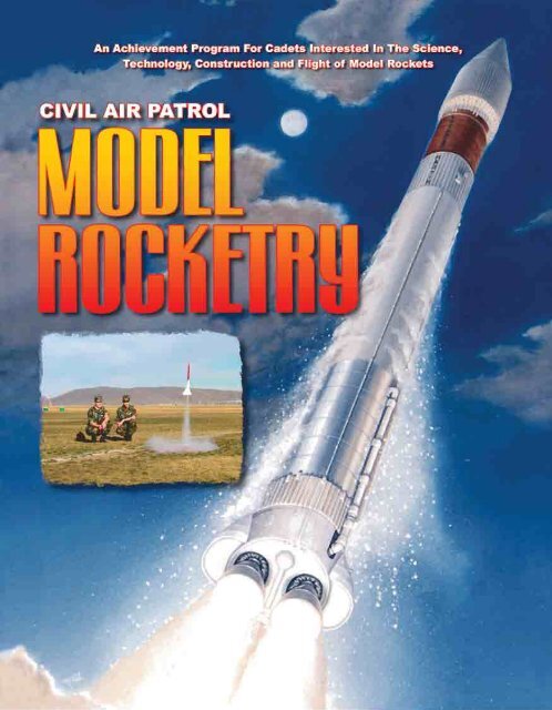
Model Rocketry - Civil Air Patrol
Model Rocketry - Civil Air Patrol
Model Rocketry - Civil Air Patrol
- No tags were found...

You also want an ePaper? Increase the reach of your titles
YUMPU automatically turns print PDFs into web optimized ePapers that Google loves.
d. OR, if the cadet lives in an area where solid-fuel model rockets are outlawed, he/she mayelect to build an air-powered rocket of his/her own design from scratch. It may be launched bya commercial launcher such as the Estes or <strong>Air</strong> Burst. If this is the case, the cadet must giveproof of the altitude attained, by the scratch-built model, using an astrolabe or a commercialmodel such as the Estes Astrotrak®. This must be verified by the QSM as part of the OWL sign-off.4. The Official Witness Log For Flight and Recovery of the <strong>Model</strong>sA qualified senior member (QSM) must witness the launch and safe recovery of the rocket. All of theNAR Safety Guidelines must be followed and the Official Witness Log (OWL) must be signed bythe QSM after these flights.5. The Role of the Squadron Commander.The squadron commander is required to sign the OWLs for the Saturn stage. After completion of thisstage, the cadet is entitled to receive the official CAP <strong>Model</strong> <strong>Rocketry</strong> Badge. It is recommended that thishonor be given to the cadet at a squadron awards ceremony.3
REDSTONEStage One4
REDSTONERequirements1. THE WRITTEN PHASEThe cadet must successfully pass a written examination on rocket history and the lives of rocket pioneers.2. THE OFFICIAL WITNESS LOG (OWL) AND TESTINGThe cadet must have the Squadron Testing Officer (STO) administer the written examination and sign theOfficial Witness Log (OWL) after a successful score is achieved by the cadet.3. THE HANDS-ON PHASEThe cadet is required to build two non-solid fuel rockets, with alternate sources of power. There are fouroptions in this text; the cadet must complete two.4. THE OFFICIAL WITNESS LOG (OWL) AND MODEL ROCKETFLIGHTSThe cadet must have a Qualified Senior Member (QSM) witness the successful launch of the two modelsbuilt with alternate sources of power.5. THE SQUADRON COMMANDERAfter completion of all the above requirements, the cadet is entitled to the Redstone certficate. TheSquadron Commander must review the completed Official Witness Logs and sign this certificate so thecadet may advance to the Titan stage. It is recommended that the certificate be presented at a squadronawards ceremony.5
REDSTONEWritten PhaseA BRIEF HISTORY OF ROCKETRY AND ITS GREAT PIONEERSPerhaps the first true rockets were "accidents!" Inthe first century AD the Chinese were reported to haveexperimented with a simple explosive powder madefrom saltpeter, sulfur and charcoal. Although these powderswere used to create small explosions in religiousfestivals, they eventually ended up in a weapon. TheChinese would fill bamboo tubes with this mixture andattach them to arrows. These "fire arrows," as they werecalled, were used at the battle of Kai-Keng where theChinese repelled the Mongol invaders with a "rocketbarrage." This occurred in the year 1232.Much later, in 1405, a German engineer by thename of Konrad Kyeser von Eichstadt devised a rocketthat was propelled by gunpowder. Another Europeancountry, France, used rockets to defend Orleans againstthe British in 1429 and again at the siege of Pont-Andemer in 1449.During the Thirty Year War (1618-1648) rocketsweighing as much as 100 pounds were fired. Theseexploded and sent small pieces of shrapnel in all directions.Rockets were extensively used in India when theywere fired at the British in the battles of Seringapatam(1792 and 1799).During the latter part of the 17th century the scientificfoundations for modern rocketry were laid by SirIsaac Newton, a great British scientist. Newton organizedhis understanding of physical motion into three scientificlaws (covered in the Titan Stage of this text).Newton's laws soon began to have a practical impactupon the design of rockets in those days. During the18th century, rockets experienced a brief revival as aweapon of war. India used rockets with great successagainst the British in 1792 and this caused ColonelWilliam Congreve, a British artillery expert, to start usingmore of a scientific approach to the development ofsophisticated rockets. He standardized the compositionfor gunpowder explosives and then added flight-stabilizingguide sticks. Congreve was able to increase therocket's range from approximately 300 to over 3000yards. Approximately 25,000 Congreve rockets wereused in 1807 at the battle of Copenhagen.In the War of 1812 between Britain and the UnitedStates, the British used rockets against the U.S. troops.During a typical siege the rockets would light up thenight sky and in the battle at Fort McHenry, in 1812,Francis Scott Key witnessed the display. This inspiredhim to write a poem which later became part ofAmerica's National Anthem, the "Star SpangledBanner."Even with William Congreve's technological developmentsthe accuracy of rockets still left much to bedesired. William Hale, an Englishman, developed atechnique called spin stabilization. In this technology,the escaping exhaust gases struck small vanes at thebottom of the rocket, causing it to spin like a bullet inflight. This gave the rocket much greater stability andaccuracy.Even with improvements in stabilization the rocketwas never used as a major military weapon until the20th century. Standard artillery was much more widelyused because of the superior accuracy of a cannon projectilefor hitting a specific target.By the end of the 19th century, men were beginningto dream of traveling into space and reaching otherplanets. To accomplish such a feat required a machinethat had great power and speed. At first, the scientificcommunity scoffed at the idea of space flight, but a fewbrave scientists continued to dream and even developexperiments using rocket power.FOUR OF THE GREATROCKET PIONEERSKonstatin Eduardovich Tsiolkovsky(1857-1935)Tsiolkovsky was a Russian teacher who madesome of the first mathematical computations for rocketflights into space. He was born in Izhevskoe, Russia,and was the 5th of 18 children. His father was a foresterby trade.6
Konstatin Eduardovich TsiolkovskyHe was a visionary and is still considered by hiscountrymen to be the first scientist to lay the foundationfor space exploration. At the age of ten, he came downwith scarlet fever and was handicapped with near totaldeafness for the rest of his life. This disability forced himto turn inward and he developed a lifelong passion forbooks. The hearing impairment forced him to leave publiceducation, and it was then young Konstatin decidedto educate himself at home. In the early 1870's, his familyrecognized the boy's brilliance and sent him toMoscow to study. Here he met Nikolai Fedorov, aneccentric philosopher who shared his radical theorieson "cosmism." This relationship had a profound effecton the future thinking of the young Tsiolkovsky.Historians agree that Nikolai Fedorov's theories inspiredTsiolkovsky's interest in space flight. In his quest to readeverything about the subject, he discovered the novelsof Jules Vern and was especially fascinated with thenovel Earth To The Moon (1865).He decided to try his own luck at writing science fictionand his work reflected technical expertise that wasbased on real science, not fantasy. This included suchpreviously unknown concepts such as microgravity,space suits and control of a rocket outside the atmosphere.Years of study paid off when Tsiolkovsky passed theexamination to become a certified teacher. He moved tothe town of Borovsk where he was assigned to teachmathematics. During this period, he met and marriedVarvara Sokolova in 1880. Over the next few years, theteacher-scientist wrote a piece titled SvobodnoeProstranstvo or "Free Space." It was never publishedduring his lifetime, but was later put into print in the midtwentiethcentury. In this historic text he spoke of vacuum,weightlessness and many of the other dangers facingfuture space voyagers. He also talked about usinggyroscopes to control the orientation of a spacecraft.In 1903, Tsiolkovsky published an article titled "TheExploration of the World Space with Jet PropulsionInstruments" in Nauchnoe Obozrenie (ScientificReview) magazine. Experts now recognize this asbeing the first true, scientifically-based proposal forspace exploration. In the article, he formulated relationshipsbetween the changing mass of a rocket as itburned fuel, the velocity of exhaust gases and the rocket'sfinal velocity. His work also included, and illustrated,a rocket engine that was fueled by liquid hydrogen andoxygen, a fuel combination that is used to this day in theSpace Shuttle. In later works, he spoke of multi-stagerockets, rocket-powered airplanes, an orbiting spacestation and eventually colonization of the galaxy.Although he never built an actual rocket, he did laymuch of the groundwork in theoretical aerospace engineering.He was a humble teacher who is, today, held inthe highest regard by the people of Russia. He is recognizedas the Father of Space Travel.Hermann Oberth(1894-1989)Hermann Julius Oberth was born on June 25, 1894in the town of Hermannstadt, Transylvania. In some circleshe too is given the title of "Father of Space Travel."His interest in rocketry started in 1905 when he was 11years old. Once again the book From the Earth To TheMoon, by Jules Verne, excited his imagination about thepossibilities of manned space exploration. After carefulstudy, Oberth realized that many of the "fantasies"found in the book, had sound scientific principles behindthem. By age 14, Oberth theorized that a "recoil rocket"Hermann Oberth7
intercontinental ballistic missiles against Great Britain.After World War II, both the U.S. and Russiaacquired German rocket scientists. These men formedthe nucleus of a program that developed into the powerfullaunch vehicles used today.DR. WERNER von BRAUN(1912-1977)Werner von Braun was one of the most importantfigures in the advancement of space exploration inaerospace history. As a youth, he was inspired, likemany others, by the fictional works of Jules Verne andH.G. Wells. During his teen years, von Braun becameinvolved in a German rocket society and used this connectionto further his desire to build large rockets. Hewas also a great follower of Hermann Oberth andworked with him in the thirties and during the developmentof German rocketry during World War II. He continuedhis college work and eventually received a PhD.in physics.Werner von Braun was the team leader of a groupthat developed the V-2 ballistic missile for the Nazisduring WWII. Today, there is still controversy over hisrole in the use of slave labor to build the highly successfulrockets. The V-2 was incredible for its time andwas eventually used in the rocket development programof the United States. The V-2 was 46 feet long, weighed27,000 pounds and had a sophisticated, but reliable liquidfuel propellant system. The rocket could fly atspeeds in excess of 3,000 miles per hour and woulddeliver a 2,200-pound warhead to a distance of 500miles from its launch site. Before the end of WWII, vonBraun managed to get many of his top rocket scientiststo surrender to the Americans. This enabled the U.S. toget most of the science and test vehicles from theGermans before the Russians.For 15 years after the war, von Braun worked withthe U.S. Army in the development of ballistic missiles.As part of the military operation, known as "ProjectPaperclip," von Braun and his team were sent to FortBliss, Texas, and did the experimental launch work atWhite Sands Proving Ground in New Mexico.Eventually, the team moved to the Redstone Arsenalnear Huntsville, Alabama.In 1960, the rocket center transferred from theArmy to a newly established organization called NASA,or National Aeronautics and Space Administration. Itwas during this time that von Braun was given the taskof developing the giant Saturn rockets. He was tobecome the chief architect of the Saturn V launch vehiclethat propelled American astronauts to the moon.He became one of the most prominent spokesmenof space exploration for the United States during thelatter part of his career. In 1970, NASA asked him tomove to Washington, D.C., to head up the strategicplanning efforts of the Administration. He leftHuntsville, Alabama, but in less than two years, retiredfrom NASA and went to work for Fairchild Industries.He died in Alexandria, Virginia, on June 16, 1977.Werner von BraunRocket posters make great cadet bulletin boardlearning tools. This poster features many of the rocketsthat were the result of pioneering work of the scientistsfeatured in this unit. It can be purchased from the Pitscocompany for under $10 and is titled as "Space Rockets."Pitsco's toll-free number is 1-800-835-0686 and itemnumber is AA52715. Cadets left to right are NathanCuellar, Kyle Drumm and Alec Atwood, of the ValkyrieSquadron, Denver, Colorado.9
REDSTONEOfficial Witness LogWRITTEN PHASE EXAMINATIONA cadet is required to have a basic knowledge of rocket history and the livesof aerospace pioneers Robert H. Goddard, Konstantin Tsiolkovsky, Werner vonBraun and Hermann Oberth. Once the cadet has studied the text and feels ready,he/she must take an examination administered by the Squadron Testing Officer(STO). The minimum passing grade for this examination is 70%. Upon successfulpassage of this test, the cadet must have the STO sign this document.CADET _________________________________________________________of______________________________________________________________Squadron, has successfully passed the written examination required of theRedstone phase.As the STO, I have administered the test and found that Cadet____________________________________________________________passed with a score that meets or exceeds the minimum requirements of theRedstone phase of the <strong>Model</strong> <strong>Rocketry</strong> achievement program.___________________________________________STO10
REDSTONEHands-on Option OneTHE FIZZY FLYERThe Completed RocketOBJECTIVE: This “Fizzy Flyer” is designed to be an entry-levelrocket. It is a rocket that is incredibly easy to build,incredibly cheap to operate, and incredibly fun forcadets.11
MATERIALS:1. 4” X 4” Piece of paper2. 1 cone shaped paper drinking cup3. tape4. scissors5. Alka SeltzerÔ or other effervescentantacid tablet6. 35mm film cannister with lid that fitsinside cannister (see page 9)PROCEDURE:Cut a sheet of paper to 4” x 4”.Apply tape to two sides of the paper asshown.Remove lid from cannister and tape oneedge to the open end about 1/2 inch upfrom opening.Carefully wrap the paper around the cannisterto form a tube. Press the remaining taped edgeto seal the tube.A common cone drinking cup is placed ontop of the tube. By holding the cone and tubeup to a light you will be able to see the top ofthe tube inside the cone and mark it asshown.To attach the nose cone, leave little tabsso that you can tape it to the rocket’stubular body. The base of the drinkingcup now becomes the rocket’s nosecone.You can make tail fins from the remainder of thedrinking cup, or from the remainder of the paperfrom which the tubular body was cut. Put tapeon the fin as shown.The fins are taped to the bottom of the rocketbody next to the cannister opening asshown. This one was made from the remainderof the drinking cup.Tape 3 fins to the rocket base to make itmore stable.12
A trash bag on a table or the floor makes a good launch pad andeasier clean-up.You are now ready to load the“fuel.” Hold the rocket nosedown, pour in 1 teaspoon of water and drop in 1/2 Alka Seltzerä.Press on the cap and position the rocket on the trash bag andwait. Countdowns are fun but it’s a little difficult to tell when theFizzy Flyer is going to take off. But that’s part of the fun.Fin PatternCut 3Fold LineFold LineFold LinePut tape ontwo edgesTape the paper to thefilm cannister here.4” x 4” Patternfor Body of RocketFor better results, use heavyweight paper, approximately60 lb. cover stock. It can bepurchased at any office supplystore.Lid that fits insidecannister13
REDSTONEHands-on Option TwoTHE GODDARD ROCKETThe completed Goddard Rocket - a foam rocket that can be built for a quarter!OBJECTIVE: This activity allows cadets to build an inexpensive,safe, flying model of a rocket.14
AN EXAMPLE: THE T.P. TORPEDOThe "T.P. Torpedo!" is made from a toilet paper cylinder, a drinking cup, one rubber band, a drinkingstraw and the fins are made from index cards. In test flights, this "junk rocket" went more than 60 feet!Not a bad performance for a freebie!MATERIALS:1. The "T.P." part of this activity is a cylinder from a roll of toilet paper.2. The "propulsion" mechanism will be a rubber band that is secured inside a cone-shaped drinking cup.3. The drinking cup will be attached to the top of the toilet paper cylinder.4. Fins are made of index cards and attached to the toilet paper cylinder.The very tip is cut off of a coneshapeddrinking cup as shown.A piece of soda straw is bent overand taped to a #64 rubber band.The rubber band is drawn throughthe hole in the cup.The cone is now cut so that it fitsthe top of the toilet paper cylinder.Cut small tabs into the cup so that itmay be taped to the t.p. cylinder.Fins like these can be cut fromindex cards and taped to the cylinder.Voila! “T.P. Torpedo,” a JunkRocket!To launch, put one thumb in the tail pipe of the cylinder, stretch the rubber band with the other and let go.Hot Glue GunCone Drinking CupToilet PaperCylinder or PaperTowel TubeTape FinFinA large blob of hot glueinside the cup holds therubber band in place andseals the hole in the cone.ElectricCord#64 Rubber BandTapeTapeTape Fin HereFin18
After countless teacher workshops andCAP activities, it has been found that thestandard PepsiÔ and CokeÔ two-liter bottlesseem to work the best.PROCEDURE:You will be adding weight to the rocketto make it come straight back down.Cut off the bottom of one of the twoliterbottles. The bottoms of the bottles mustbe identical.The idea is to mount several washers to thetop of the bottom of a pop bottle. The bottomof the bottle will become the top or nose ofthe rocket. To do this, washers are going tobe duct-taped to a rocket bottle and securedwith a cap from another pop bottle.The washers are positioned as shown ontop of the rocket bottle.The bottom cap that you removed from theother pop bottle is now placed over thewashers and duct-taped to the rocket bottle.Fins can be made from just about anything;however, cardboard works very well andtakes the abuse of repeated flights.The fin pieces are split about 1” up from thebottom as shown. A snap knife works wellfor this task.The reason for the splitting of the fin can beseen here. Each "flap" is used to secure thefin in place on the rocket bottle. Duct tapeworks very well for this mounting.Here's your completed pop bottle rocket. Tomake it fly, add a little water, mount it on alaunching platform, secure it with a pin, adda little pressure (start out small and workupward in pressure) then pull the pin.20
Cut off bottom ofanother bottleSteel washerDuct tapeupper capto bottleDuct tapesplit fin tobottleSplit cardboard finWater Rockets I-IIITeacher Handbook,a highly recommended guide isavailable from Pitsco. See page 78for address and toll free number.21
22. Drill bits, 5/8" and 7/32".23. Dremmel tool.24. Hack saw.25 Hammer.26. Broom handle.LET'S BUILD IT!PROCEDURE:1. Using a saw, cut a piece of ¾" to 1" plywood to a 1" x 4" x 16". Ifyou look around, places like Home Depot will often have scraps thatare free. In some instances, they will even cut the piece if you tellthem you are doing a CAP project in rockets!2. Your electrical box will have two holes pre-drilled on each side.Ream out four of these holes (two each on opposite sides with a7/32" bit.) These holes will be used to secure the U-shaped retainingpin made from the 3/16" rod.3. Drill a 5/8" hole in the middle of the base. The hole should be approximately7" from one end. Enlarging this opening slightly witha Dremmel tool will allow for easier assembly.4. Using a hack saw, cut a 12" length of the 3/16" diameter rod. Bendthe rod around a broom handle. That makes a nice "U" shape.Now test it in the electrical box so that slides easily in all four holesas shown in the illustration.5. Attach the legs to the bottom of the launch pad using 1" woodscrews.6. A large nail will be used to hold the launcher to the ground. A ½" to5/8" hole should be drilled in one of the elevation blocks to hold thenail when not in use.7. Attach a stop block into position as shown in the illustration. It willtake two 2" screws to keep it secured to the launch pad. A 7/32"inch hole should be drilled into this stop block so that the nylon pullcord can be attached to the U-shaped retaining pin and a handle onthe other end.8. Punch out the center hole of the electrical box. Attach it to the baseplatform so that the hole in the bottom of the box is over the 5/8"opening. Also make sure that the holes for the retaining pin arealigned as shown in the illustration. Use two ¾" #10 wood screwsto secure the electrical box to the launch platform.9. Drill an additional 5/8" hole in the opposite end of the pad from thestop block. This will be an anchor hole and will go all the waythrough the pad. A large nail goes through this hole and securesthe pad to the ground during launch.10. Using something like a liquid detergent, lubricate the inside of theends of your garden hose piece.11. Slip the PVC elbow into one end of the garden hose and secure itwith a hose clamp as shown in the illustration.12. Place the large end of the valve stem into the other end of the hose.Place the hose clamp slight ahead of the valve stem bulge and thentighten. This is essential to stop the valve stem from being blown outof the hose as pressure is added.13. Place the PVC elbow through the 5/8" air inlet hole in the base platform.You may have to tap it in with your hammer. Secure theelbow with the ½ " Conduit strap and wood screws (#8 wood screws).14. Add one or two 5/8" metal washers, then slip the cone gasket overthe end of the PVC pipe.23
15. Drill a 7/32" hole through the center of the handle and threadthe cord through this hole. Knot it. Slip the cord through the holein the stop block and tie the other end to the "U-shaped" retainingpin.16. The cone washer is mounted over the elbow and when in position,will seal the pop bottle. The retaining pin will keep it frommoving while pressure is applied.Compressed <strong>Air</strong>Inlet holePressure Hose AssemblyPVC Elbow5’ x 5/8”ValveStemScrewsConduitStrapHoseClampElectrical BoxAnchorHoleConeWasherLaunch PlatformLegsValve StemStopBlockGardenHosePermission to use the features of these illustrations granted by Insights Visual Productions, Inc.24
REDSTONEOfficial Witness LogHANDS-ON PHASEWhen a cadet completes the written examination, he/she isrequired to have a Qualified Senior Member (QSM), witness thesuccessful launch of TWO non-solid fuel rockets with alternatesources of power. After witnessing the successful flight of theserockets, the QSM must sign this Official Witness Log (OWL).CADET ______________________________________________of___________________________________________________Squadron, has selected the following two rockets to build of thefour listed below.1. The Fizzy Flyer2. The Goddard Rocket (a foam tube and rubber band rocket)3. The Junk Rocket (a paper tube, rubber band, paper cup andfins model)4. The Pop Bottle Rocket (a compressed air model using a oneor two liter pop bottle for the main body of the rocket)As the QSM, I have witnessed the successful flight of each ofthe chosen rockets.___________________________________________STO/QSM25
REDSTONE STAGESquadron Commander’sApprovalI have reviewed the Official Witness Logs, both writtenand hands-on, of Cadet_________________________________________________and have found that this individual has successfullypassed the Redstone Stage requirements and is now qualifiedto advance to the Titan Stage of the <strong>Model</strong> <strong>Rocketry</strong>Program of the <strong>Civil</strong> <strong>Air</strong> <strong>Patrol</strong>.The cadet will be now be awarded a certificate ofCompletion of the Redstone Stage.___________________________________________Squadron Commander26
TITANStageTwo27
TITANRequirements1. THE WRITTEN PHASEThe cadet must successfully pass a written examination on Newton’s Laws of Motion andthe Rocket Aerodynamics.2. THE OFFICIAL WITNESS LOG (OWL) AND TESTINGThe cadet must have the Squadron Testing Officer (STO) administer the written examination and sign the Official Witness Log (OWL) after a successful score is achieved by thecadet.3. THE HANDS-ON PHASEThe cadet is required to build a commercial, single-stage, solid-fuel model rocket, or if livingin an area where model rockets are banned, launch an air-powered rocket. (See thesection on TITAN AIR-POWER OPTION at the end) The cadet is also required to build asingle stage model rocket that is a replica of one that was part of aerospace history.4. THE OFFICIAL WITNESS LOG (OWL)FOR CONSTRUCTION ANDFLIGHT OF THE REQUIRED MODEL ROCKETSA QSM must first examine and then witness the successful launch, flight and recovery ofthe model rockets required in this stage. It is the responsibility of the QSM to see that allNAR Safety Code guidelines are followed in the rocket launches.5. THE ROLE OF THE SQUADRON COMMANDERThe squadron commander must sign the Titan Certificate.28
<strong>Model</strong> RocketSAFETY CODEThis official <strong>Model</strong> <strong>Rocketry</strong> Safety Code has been developed and promulgated by the National Association of <strong>Rocketry</strong>.(Basic Version, Effective February 10, 2001)1. MATERIALS. I will use only lightweight,non-metal parts for the nose, body and fins of myrocket.2. MOTORS. I will use only certified, commercially-maderocket motors, and will not tamperwith these motors or use them for any purposesexcept those recommended by the manufacturer.3. IGNITION SYSTEM. I will launch myrockets with an electrical launch system andelectrical motor igniters. My launch system willhave a safety interlock in series with the launchswitch, and will use a launch switch that returnsto the “off” position when released.4. MISFIRES. If my rocket does not launchwhen I press the button of my electrical launchsystem, I will remove the launcher’s safety interlockor disconnect its battery, and will wait 60seconds after the last launch attempt beforeallowing anyone to approach the rocket.5. LAUNCH SAFETY. I will use a countdownbefore launch, and will ensure that everyoneis paying attention and is a safe distance ofat least 15 feet away when I launch rockets withD motors or smaller, and 30 feet when I launchlarger rockets. If I am uncertain about the safetyor stability of an untested rocket, I will check thestability before flight and will fly it only after warningspectators and clearing them away to a safedistance.6. LAUNCHER. I will launch my rocket froma launch rod, tower, or rail that is pointed to within30 degrees of the vertical to ensure that therocket flies nearly straight up, and I will use ablast deflector to prevent the motor’s exhaustfrom hitting the ground. To prevent accidental eyeinjury, I will place launchers so that the end of thelaunch rod is above eye level or will cap the endof my launch rod when it is not in use.7. SIZE. My model rocket will not weigh morethan 1500 grams (53 ounces) at liftoff and will notcontain more than 125 grams (4.4 ounces) ofpropellant or 320N-sec (71.9 pound-seconds) oftotal impulse. If my model rocket weighs morethan one pound (453 grams) at liftoff or has morethan 4 ounces (113grams) of propellant, I willcheck and comply with Federal AviationAdministration regulations before flying.8. FLIGHT SAFETY. I will not launch myrocket at targets, into clouds or near airplanes,and will not put any flammable or explosive payloadin my rocket.9. LAUNCH SITE. I will launch my rocketoutdoors, in an open area at least as large asshown in the accompanying table, and in safeweather conditions with wind speeds no greaterthan 20 miles per hour. I will ensure that there isno dry grass close to the launch pad, and that thelaunch site does not present risk of grass fires.Installed TotalImpulse (N-sec)0.00 - 1.252.26 - 2.502.51 - 5.005.01 -10.0010.01 - 20.0020.01 - 40.0040.01 - 80.0080.01 - 160.00160.01 - 320.00EquivalentMotor Types1/4A,1/2AABCDEFGTwo G’sMinimum SiteDimensions (ft)501002004005001,0001,0001,0001,50010. RECOVERY SYSTEM. I will use a recoverysystem such as a streamer or parachutein my rocket so that it returns safely and undamagedand can be flown again, and I will use onlyflame-resistant or fireproof recovery systemwadding in my rocket.11. RECOVERY SAFETY. I will not attemptto recover my rocket from power lines, tall trees,or other dangerous places.29
anced. The surface of the pad pushes the rocket upwhile gravity pulls it down. As the engines ignite, thethrust from the rocket unbalances the forces, and therocket travels upward. Later, when the rocket runs out offuel, it slows down, stops at the highest point of its flight,then falls back to Earth.Objects in space also react to forces. A spacecraftmoving through the solar system is in constant motion.The spacecraft will travel in a straight line if the forceson it are in balance. This happens only when the spacecraftis very far from any large source of gravity sourcessuch as the Earth or other planets. If the spacecraftcomes near a large body in space, the gravity of thatbody will unbalance the forces and curve the path of thespacecraft. This happens, in particular, when a satelliteis sent by a rocket on a path that is parallel to the Earth'ssurface. If the rocket shoots the spacecraft fast enough,it will orbit the Earth. As long as another unbalancedforce, such as friction with gas molecules in orbit or thefiring of a rocket engine in the opposite direction from itsmovement, does not slow the spacecraft, it will orbit theEarth forever.A formal statement of Newton's First Law of Motionis: a body in a state of rest and a body in motion tend toremain at rest or in uniform motion unless acted upon bysome outside force.NEWTON'S SECOND LAW OF MOTIONThe second law states: The rate of change in themomentum of a body is proportional to the force actingupon the body and is in the directon of that force. Thislaw is essentially a statement of a mathematical equation.The three parts of the equation are "mass" (m),"acceleration" (a) and "force." (f). The basic formula isf = m x a. The amount of force required to accelerate abody depends on the mass of the body. The more mass,the more force required to accelerate it.The term "acceleration" is defined as the rate ofchange in velocity with respect to time. Use a cannon asan example to help understand the application of thelaw. When the cannon is fired, an explosion propels acannon ball out the open end of the barrel. The projectileflies to its target. At the same time, the cannonrecoils, or is pushed backward. The force acting on thecannon and the projectile is the same. Since f = m x a,if the mass increases, the acceleration decreases; onthe other hand, if the mass decreases, the accelerationincreases.Applying this example to a rocket, replace themass of the cannon projectile with the mass of thegases being ejected out the rocket engine. Replace themass of the cannon with the mass of the rocket movingin the other direction. Force is the pressure created bythe controlled explosion taking place inside the rocket'sengine. That pressure accelerates the gas one way andthe rocket the other.NEWTON'S THIRD LAW OF MOTIONBeyond any doubt, this is Newton's most oftenquoted scientific law! Imagine Sir Isaac, in his eloquentEnglish voice, stating, "For every action there is anequal and opposite reaction." The law is so profound,so important, it is the foundation of "rocket science".The engine creates the action and the forward motion ofthe rocket is the "opposite reaction".A rocket can lift off from a launch pad only when itexpels gas out of its engine. The rocket pushes on thegas and the gas in turn pushes on the rocket. Theaction is the expulsion of gases out of the engine; thereaction is the movement of the rocket in the oppositedirection.NEWTON'S LAWS COMING TOGETHERAn unbalanced force must be exerted for a rocketto lift off from a launch pad or for a craft in space tochange speed or direction (Newton's First Law). Theamount of thrust (force) produced by a rocket enginewill be determined by the mass of rocket fuel that isburned and how fast the gas escapes the rocket(Newton's Second Law). The reaction, or forwardmotion, is equal to and in the opposite direction of theaction, or thrust, from the engine (Newton's Third Law).ROCKET AERODYNAMICSBASICS OF STABILITYAND FORCES IN FLIGHTA rocket is very much like an arrow. It has a longcylindrical body with fins at the back for stability. If arocket is stable, it will fly well; on the other hand, if it isunstable its flight will be erratic, at best.All matter, regardless of size, mass, or shape has acenter of gravity. The center of gravity is the exact spotwhere all of the mass of the object is perfectly balanced.You can easily find the center of gravity of an object,such as a ruler, by balancing it on your finger. If thematerial used to make the ruler is of uniform thicknessand density, the center of gravity should be at thehalfway point between one end of the stick and theother. If the ruler were made of wood, and a glob of claywere stuck on one end, the center of gravity would shifttoward the weight and away from the middle. You wouldthen have to move your finger toward the weighted endto find the balance point.It is easy to see this concept when applied to arocket. When the engine is installed, the center of gravitywill move toward the rear. If a payload is added to the31
front of the rocket, the center of gravity will again shiftand most likely end up at a different balance point thanwhen the rocket was empty. A change in the center ofgravity will also occur when fuel is burned off in the rocketengine.One of the first things a rocket builder learns is thata model will not fly right unless it is aerodynamically stable.Stability means that it will tend to keep its nosepointed in the same direction through its upward flight.Good aerodynamic stability keeps the rocket on a trueflight path even though outside forces try to make itbecome erratic and unpredictable. The end result of theflight may be tumbling and a possible crash.In the illustration below you see a line going from noseto tail. This is the longitudinal axis and a movement aroundthis axis is called roll. A line going through the center of gravity,from side to side, is known as the lateral axis and movementaround this axis is called pitch, or nose-up, nosedown.When the nose of a rocket swings from side to side,the tail moves in the opposite direction because the rotationoccurs around its vertical axis. When the nose moves right,the tail moves left, and vice versa. Movement around thisaxis is called yaw.Notice in the illustration there is another “center,”and it is known as the center of pressure. The center ofpressure exists only when air is flowing past the movingrocket. This flowing air, rubbing and pushing against theouter surface of the rocket, can cause it to begin movingaround one of its three axes. For an example of thisconcept, think of a weather vane shaped like an arrow.This arrow is mounted on a rooftop and is used fortelling wind direction. The arrow is attached to a verticalrod that acts as its pivot point. The arrow is balanced sothat the center of gravity is right at the pivot point. Now,when the wind blows, the arrow turns, and the head ofthe arrow points into the on-coming wind. The reasonthat the weather vane arrow points into the wind is thatthe tail of the arrow has a much larger surface area thanthe arrowhead. The flowing air imparts a greater forceto the tail.If the center of pressure were in the same place asthe center of gravity, neither end of the arrow would befavored by the wind and the arrow would not point. Thecenter of pressure is between the center of gravity andthe tail end of the arrow. This means that the tail endhas more surface area than the nose end.It is extremely important that the center of pressureof a model rocket be located toward the tail and the centerof gravity be located more toward the nose. If theyare very near each other, the rocket will be unstable inflight. With the center of pressure located in the rightplace, the rocket will remain stable.FLIGHT TESTThe model is tested by first loading it with theengine, wading and all other attachments. A loop in theend of a six to ten foot long string is attached to themodel at the center of gravity. When suspended, thestring should be at 90° to the rocket’s body. Slide theloop to the proper position around the rocket and secureit with a small piece of tape.With the rocket suspended at its center of gravity,swing it around in a circular path. If the rocket is verystable, it will point forward into the wind created byits forward motion. This wind, by the way, is known asthe relative wind.Some rockets, although stable, will not point forwardon their own accord unless they are started32
straight. This is done by holding therocket in one hand with an armextended and then pivoting the entirebody as the rocket is started on its circularpath. It may take severalattempts before a good start isachieved.If it is necessary to hold the rocketto start it, an additional test couldbe made to determine when themodel is stable enough to fly. Movethe loop back on the body until thetube points down at about a 10° anglebelow the horizon. Repeat the swingtest. If the model points its noseahead once started, it should be stableenough to launch.It is recommended that a rocketnot be launched until it has passedthe stability test. If the rocket does notpass the stability test, it can usuallybe made stable. Two methods can beused: the balance point can bemoved forward, or the fin area can beenlarged. To move the balance pointforward, add weight to the nose cone.For models with hollow plastic nosecones, simply pack some modelingclay into the tip of the nose. To addweight to balsa nose cones, attachwashers to the base of the coneswhere the parachute is attached. Thecenter of gravity can also be movedforward by adding a payload sectionto the model. Fins can either bereplaced with larger ones or additionalfins can be added to the model.Once modifications are made, swingtest the model until it flies in aSTRAIGHT ARC.A MODEL THAT IS BUILT ANDTESTED PROPERLY WILL BE AJOY TO FLY.The model is tested by first loading it with the engine, wading and all other attachments.A loop in the 6-10' string is attached to the model at the center of gravity. When suspended,the string should be at 90° to the rocket's body. Secure it with a small piece of tape.With the rocket suspended at its center of gravity, swing it around in a circular path. If therocket is very stable, it will point forward into the wind created by its forward motion. Thisis known as the relative wind.33
TITANOfficial Witness LogWRITTEN PHASE EXAMINATIONThe cadet is required to take an examination on Newton's Laws andRocket Aerodynamics. Once the cadet has studied the text and feels ready,he/she must take an examination administered by either the SquadronTesting Officer (STO) or other qualified Senior Member (QSM). The minimumpassing grade for this examination is 70%. Upon successful passage of thistest, the cadet must have the STO or QSM sign this document.CADET______________________________________________________of__________________________________________________________Squadron, has successfully passed the written examination on Newton’sLaws and Rocket Aerodynamics of the Titan Stage of the <strong>Model</strong> <strong>Rocketry</strong>Program.As the STO, or QSM, I have administered the test and found that Cadet__________________________________________ passed with a scorethat meets or exceeds the minimum requirements of the Titan phase of the<strong>Model</strong> <strong>Rocketry</strong> achievement program.___________________________________________STO/QSM34
TITANHands-on Option OneCOMMERCIAL SINGLE-STAGE MODEL ROCKETThe Completed Estes Alpha RocketOBJECTIVE: This is the cadet’s first opportunity to build an entrylevel, solid fuel powered, single-stage commercialrocket.35
BUILDING THE ESTES ALPHA,A CLASSIC ENTRY-LEVEL MODEL ROCKETTo meet the hands-on requirements of this phase, itis necessary for the cadet to build a single-stage, solidfuelmodel rocket. The author has elected to use, forillustration purposes, the Estes Alpha; it has beenaround for years and is still one of the best to learn thebasics. The author realizes that the majority of cadetshave already built model rockets, many to a veryadvanced level. However, after observing thousands of<strong>Civil</strong> <strong>Air</strong> <strong>Patrol</strong> and secondary school model projects,one thing stands out above all others, very few buildersreally know how to properly finish a model. So manyrockets end up looking like cardboard toys that havebeen hastily built and quickly launched.With great appreciation and thanks, Ann Grimm,Director of Education for Estes-Cox Incorporated, hasprovided the author with permission to use all of theinstructions and illustrations from those published withtheir model rocket line. We begin with the instructionsfor the Estes Alpha.The author has included the "<strong>Model</strong> RocketNomenclature" first. This will allow the cadet to learn the"language" of a model rocket. Following this is the"<strong>Model</strong> Rocket Flight Profile", and it will acquaint thebuilder with a picture of the launch-to-touchdown action.At this time, the cadet is asked to review thenomenclature, list of parts ("Exploded View"), neededsupplies, and building steps. Then it is recommendedthat the cadet buy a model rocket similar to the Alpha inbasic construction. The author will take the cadetbeyond the instructions into the exciting realm of modelpaint and finishing. Once completed, it should be arocket that will be a source of great pride for the builder.The model featured in this unit has graphics that aresimilar to the <strong>Civil</strong> <strong>Air</strong> <strong>Patrol</strong>'s search and rescue airplanes.It is a striking red, white and blue finish with anofficial CAP seal. Let the fun begin!EngineHolderAssemblyEngine Holder TubeNose ConeEyeletAdapter RingShock CordShroudLinesEngine HookShock Cord MountBody TubeLaunch LugLeading EdgeTipRootEdge(Attachesto BodyTube)Engine HolderAssemblyParachuteTrailing EdgeALPHA ROCKETPARTSFin Part NamesFins36
MATERIALS:In the Estes Alpha instruction sheet, it states, "you will need these construction supplies. Each step showswhich supplies will be required." You will need a ruler, pencil, hobby knife, glue (white or yellow), scissors, sandpaper,masking tape, sanding sealer and paint.PROCEDUREAll too often, cadets get in ahurry and construct a model rocketwith very little reference to theinstructions. It is highly recommendedthat the builder go overeach step carefully and arrangethe parts in the order that they willbe used in construction.Cadet Nathan Cuellar, of theValkyrie Squadron, in Denver,Colorado, reads over the EstesAlpha instruction sheet beforebeginning the project.601001502404006001500Grit GuideCoarseMediumFineVery FineSuper FineUltra FineUltra Micro FineNot everybody knows the differencein sandpaper. To be sure, follow thisgrit guide and purchase a sheet thatwon't damage the balsa used onmodel rockets. Something in therange of 150-240 works well forsanding fins.Masking tape can be used to hold sandpaperto a flat surface. This makes a solidbase for sanding edges and flat surfaces.The builder can also use a sanding block.The paper is wrapped around a block forsanding the balsa pieces. This creates aflat surface when sanded.The fins can be held together and the surfacessanded. This makes all of the finsuniform.The leading edges can be rounded usingthe same technique.It is highly recommended that the builderuse a sanding sealer on the balsa. Thisseals the surface and makes a more professionallooking paint finish.The body can also be sealed. Sandableautomotive primer surfacer also works well.37
For sanding rounded surfaces, you can purchasea foam sanding pad at most hobbyshops and some home supply stores.Cadet Alec Atwood applies one of two of therecommended adhesives for this type ofmodel rocket. Both white and yellow glueswork well.When the fins are properly aligned andglued, there should be no glue showing. It isimportant to have the Alpha fins 120° apart.To make a really outstanding finish, theauthor recommends that the builder start outwith a sandable automobile primer, or primersurfacer. The rocket body can be held by arolled piece of paper stuffed in the open endand the first primer coat should be a "mist,"or very light application. Follow with two wetcoats after the mist coat dries. Let the twowet coats set for several hours, or overnight, so the primer can "gas out." Thismeans that all of the solvents in the primerhave a chance to evaporate. Make sure thatthe primer is applied in a well-ventilatedarea.White putty, purchased at a hobby shop, canbe used to fill in the imperfections in theprimer finish. It can also be used to make anice, rounded fillet between the fins and body.When using sandpaper, be careful of thistechnique. The finger pressure can actuallydig into the surface and make it uneven.When sanding the area where the fin hasbeen bonded to the body, be very careful.To make a round sanding "tube," roll a pieceof sandpaper around a dowel rod or pencil.It is recommended that very fine sandpaper be used for the final step. After spraying oneor two final coats of automotive primer, carefully sand the surface with a finer grade ofpaper. It is recommended that the builder let the rocket set for at least two days so theprimer has a chance to cure.38
Once the finish is flawless, it's time to paint.The author recommends a high qualityhobby grade of paint for the rocket's base, orfirst, coat.For the rocket used in this publication, theauthor used Tamiya TS 16 Pure White as thebase coat. The rocket was held with a dowelrod while being sprayed. The first two coatsare light mist followed by two wet coats. Letthe model dry for about 15 minutes betweencoats.Once the builder is satisfied with the finish, itis highly recommended that the rocket beallowed to set overnight. As a matter ofsafety, ALWAYS PAINT YOUR MODELS INWELL VENTILATED AREAS. NEVERPAINT NEAR A STOVE OR ANY OPENFLAME. SOME PAINTS WILL IGNITE. Andof course, wear eye protection.If the builder wants to have a custom finish,with several colors, thin masking tape will beneeded. These small roles can be purchasedat hobby and automotive paint supplystores.The thin (1/8 or 1/16) tape is applied to makea graphic such as this curved line. (See thephotograph of the finished rocket).To make a larger masking paper, applymasking tape so that ½ of the tape is on thepaper and the other ½ is open.The masking tape open edge is laid downon the thin tape line. Make sure that it isproperly aligned and sealed so that spraypaint won't "bleed" through.Tamiya's TS 19 Metallic Blue was used for asecond color. First apply a mist coat allowingsome drying time between coats. If thebuilder gets in a hurry, runs and sags mayoccur.After the mist coat dries, apply a full colorcoat. Let dry for at least 20 minutes.39
Two wet coats are applied and it is recommendedthat the builder let it dry overnight.The masking paper and thin line tape can beremoved after the paint is cured.Here is a tip for making some spectaculargraphics. Go to a shop that makes vinylsigns and see if they have some scraps inthe colors you want. Most of the vinyl usedon computer signs is as thin as a coat ofpaint! It is recommended that the builderexperiment with these scrap sheets of vinylon something like a two-liter pop bottle,before putting it on the body of the rocketmodel. Automotive striping tape shownabove also works on models. The stripingtape comes in various widths and colors.The author used automotive striping tape forsecond line shown here. Next, a piece was cutfrom the vinyl sheet to make the graphic forone of the fins.LAUNCH SUPPLIESTo finish off the "look," the author used theCAP seal that was purchased from theBookstore catalog. They are inexpensiveand give the rocket an "official" look!The finished product can beseen on the TITAN Hands-OnOption One page.MISFIRESTo launch your rocket you will need the following items:1. Estes Electrical Launch Controller and Launch Pad2. Estes Recovery Wadding No 22743. Recommended Estes Engines: A8-3 (First Flight), A8-5.B4-4, B4-6, B6-4, B6-6, B8-5,C6-5 or C6-7To become familiar with your rocket’s flight pattern, use an A8-3 engine for your first flight. Use only Estes products to launchthis rocket.FLYING YOUR ROCKETA. Choose a large field away from power lines, tall trees, and lowflying aircraft.Try to find a field at least 76 meters ( 250 feet)square. The larger the launch area, the better your chance ofrecovering your rocket. Football fields and playgrounds aregreat.B. Launch area must be free of dry weeds and brown grass.Launch only during calm weather with little or no wind and goodvisibility.C. Don’t leave parachute packed more than a minute or so beforelaunch during cold weather [colder than 4 o Celsius(40 o ) Fahrenheit].Parachute may be dusted with talcum powder to avoid sticking.If the igniter functions properly but the propellant does notignite, keep in mind the following: An estes igniter will functionproperly even if the coated tip is chipped. However, if the coatedtip is not in direct contact with the engine propellant, it will onlyheat and not ignite the engine.When an ignition failure occurs, remove the safety key fromthe launch control system and wait one minute before approachingthe rocket. Remove the expended igniter from the engine andinstall a new one. Be certain the coated tip is in direct contact wihthe engine propellant, then reinstall the igniter plug as ilustratedabove. Repeat the countdown and launch procedure.FOR YOUR SAFETY AND ENJOYMENTAlways follow the NAR (National Association of <strong>Rocketry</strong>) MODELROCKETRY SAFELY CODE while participating in any model rocketryactivities.COUNTDOWN AND LAUNCH10.....BE CERTAIN SAFETY KEY IS NOT IN LAUNCHCONTROLLER40
9......Remove safety cap and slide launch lug overlaunch rod to place rocket on launch pad. Make sure therocket slides freely on the launch rod.8......Attach micro-clips to the igniter wires. Arrange theclips so they do not touch each other or the metal blastdeflector. Attach clips as close to protective tape on igniteras possible.7......Move back from your rocket as far as launch wire willpermit (at least 5 meters - 15 feet).6......INSERT SAFETY KEY to arm the launch controller.Give audible countdown 5...4...3...2...1LAUNCH!!FINLAUNCHLUGFINMATCH LINESALPHATUBE MARKINGGUIDEFINLAUNCHLUGFINALPHAPATTERNSSHOCK CORDMOUNTSECTION 3PUSH AND HOLD LAUNCH BUTTON UNTIL ENGINEIGNITES.REMOVE SAFETY KEY FROM LAUNCH CONTROLLER.KEEP SAFETY KEY WITH YOU OR REPLACE SAFETYKEY AND SAFETY CAP ON LAUNCH ROD.FINMATCH LINESOVERLAP TABFINSECTION 2SECTION 1If you use the ultrasafe E2Ô or CommandÔ LaunchControllers to fly your models, use the following launchsteps:A. After attaching micro-clips, etc., insert the safety keyinto the controller recepticle. If the igniter clips havebeen attached properly to the igniter, the red L.E. D. willnow begin to flash on and off and the audio continuity indicatorwill beep on and off.B. Hold the yellow (left) arm button down. The L. E. D. willstop flashing and the audio indicator will produce asteady tone.C. Verbally count down from five to zero loud enoughfor the bystanders to hear. Still holding the yellow armbuttondown, push and hold the orange (right) button downuntil the rocket ignites and lifts off.Launching the rocket is Cadet Kristopher Turner.Standing by is Cadet David Van der Vieren. Bothare members of the Dakota Ridge CompositeSquadron, Littleton, Colorado.Cadet Stark watches as Cadet Kevin Rutherford prepareshis rocket for lift off.41
5. <strong>Model</strong> reaches peakaltitude. Ejectioncharge activatesrecovery system.6. Recoverysystems aredeployed4. Tracking smokegenerated duringtime delay/coastphase3. Engine burns outand rocket continuesto climb during thecoast phase.MODELROCKETFLIGHTPROFILE7. Rocket safelyreturns to2. Rocket acceleratesand gains altitude1. Electrically ignitedrocket engine provides8. Touchdown!Replace the engine,igniter, and recoverywading.Ready to launch42
TITANHands-on Option TwoCOMMERCIAL SINGLE-STAGE MODEL ROCKETThe Estes Mercury-Redstone with Liberty Bell 7OBJECTIVE: The cadet can opt to build a scale model of an actual rocket that was asignificant part of aerospace history. At this writing, there were numerous offerings suchas the Phoenix, the V-2, the AGM-57X Heatseeker, and Saturn, all by Estes-CoxCorporation, and from Quest there is DCY Space Clipper, and the Tomahawk SLCMCruise Missile, just to name a few. The requirements are that the model be a single-stagerocket and the cadet must show proof that the model is a replica of one that actuallyexisted.The model selected for an example is the currently offered Redstone-Mercury with theLiberty Bell 7 capsule. Recently, this capsule was recovered from the ocean and is beingshown around the United States at various locations. The author recommends this onebecause of the incredible amount of documentation available on both the rocket and the43
The author recommends thebook LOST SPACECRAFT, TheSearch For Liberty Bell 7. This givesnot only a fascinating account ofhow a team actually recovered thesunken capsule, it also covers thelife history of astronaut GusGrissom and the United Statesspace program of that time (1961).The Liberty Bell 7 was lost at sea onJuly 21, 1961, during America's secondmanned space mission. Anaccident happened shortly after thecapsule returned from its flight and thecontroversy still rages to this dayconcerning its sinking.Because of its importance inaerospace history and the mysterysurrounding the sinking of the capsule,the author has selected theEstes Redstone-Mercury modelrocket with a replica of Grissom'sLibery Bell 7 for the example"option" in this stage.It is recommended that thecadet research the model that wassignificant in aerospace history. Theauthor has selected for this option,the Mercury-Redstone that carriedGus Grissom aloft in Liberty Bell7.PROCEDURE:As always, it is good idea to laythe parts out and spend some timereading the instructions. One of themost important benefits is to learnthe sequence of building a rocketthe right way.The author has chose the Estes Mercury-Redstone with Liberty Bell 7 as the samplemodel.The author found that theescape tower mechanism proved tobe difficult. It is suggested that just asmall amount of plastic be clippedfrom the edges of this triangularpiece. It allows the tower structureto be glued without distortion.Every effort should be made not toget the plastic cement on the fingers;smearing this on the surface ofthe model will damage it.Once the structure is cemented,according to the instructions, the capsulecan be painted flat black and the towerstructure a flat red.This is what the engine assembly looks likewhen completed. The horizontal structureswill hold the fins when properly mounted inthe body of the rocket.A fascinating book, LOST SPACECRAFT, anda Discovery Channel VHS video, In Search ofLiberty Bell 7, are outstanding sources ofinformation about the controversial sinking,and recovery, of one of NASA's spacecraft.The mission patch shown is a replica of theone issued for America's second mannedspace flight.In some kits, the tower structure is white, inothers it's red. The white one was used forclarity.Once the engine housing isinserted into the body, it is a goodidea for the builder to "pre-fit" thefins. To make the fins fit the slot, ahobby knife can be used to trim thetabs.MATERIALS:A model kit of a rocket that wassignificant in aerospace history.While the escape tower structureis drying, the builder can starton the Liberty Bell 7 capsule. Thisgoes together reasonably well, butcare should be used when fitting thesides of the three parts together.44
Before the fins are glued to the engine mounting,the lower body graphics must be applied.Now the upper graphics and "United States" decals areto be applied. Note that the capsule has been painted flatblack and the escape tower has been painted red.. It's time to launch "Gus" so check to make sure theproper amount of wading is placed in the body along withthe two required parachutes.There is a coupling ring that has to be glued inposition to bring the upper and lower body halvestogether. Be careful when gluing this and make surethe body tube is perfectly aligned.Cadets Jesse Macku and Kevin Rutherford, of the Dakota RidgeComposite Squadron, Littleton, Colorado, prepare the Redstone forlaunch.The parachutes are glued into the body asshown in the Kit instruction sheet. Before launching,these chutes should be removed and dusted withtalcum powder.Cadet Kevin Rutherford presses thefiring button on the Quest launcherand Redstone heads skyward!45
The completed Mercury-Redstone is an awesome-looking model. To make the Liberty Bell 7 capsule look even more realistic,Estes has included the proper graphics showing the "crack" painted on the surface.46
TITANThe <strong>Air</strong> Power OptionTHIS OPTION IS NOT FOR EVERYONE!Cadet Ryan Lacy brings the pressure to nearly 80pounds for a launch of the <strong>Air</strong> Burst rocket. FirstLieutenant Chuck Sellers witnesses the launchThis option is only available to cadets who live in a city, county, or state, wherecommercial, solid-fuel model rockets are against the law and only after a cadet presentswritten proof that solid-fuel rockets are against the law in the city, county, orstate surrounding the squadron to which the cadet belongs.OBJECTIVE: The cadet is required to launch an air-powered model rocket, determineits altitude and recover it safely.47
TITANAIR POWER OPTIONRequirements1. THE WRITTEN PHASEThe cadet must successfully pass a written examination on Newton’s Laws of Motion andthe Rocket Aerodynamics.2. THE OFFICIAL WITNESS LOG (OWL) AND TESTINGThe cadet must have the Squadron Testing Officer (STO) administer the written examination and sign the Official Witness Log (OWL) after a successful score is achieved by thecadet.3. THE HANDS-ON PHASEThe cadet is required to purchase, borrow, or share a commercial air-powered rocket andlauncher. The apparatus must then be constructed according to the manufacturer’s instructions.Once built, the cadet must safely launch and recover the air-powered rocket. Thecadet must then determine the altitude of the air launched rocket by using an altitudetracker (as featured in Aerospace Dimensions, Module 4, Rockets), or a commercial altitudetracker, such as Estes AltitrackÔ. The cadet may also use the equations and tables,illustrated in the text of the “It’s Rocket Science” article found in the test, to show how todetermine the rocket’s altitude using mathematics.4. THE OFFICIAL WITNESS LOG (OWL)A QSM (Qualified Senior Member) must witness the cadet’s launch, altitude determination,and safe recovery of the air-powered rocket. The cadet is also required to have aworking knowledge of the NAR Safety Code and must apply those guidelines which wouldbe relevant to air powered flight. Once the QSM feels the cadet has met the basic requirementsof this Option, he/she may sign off on the Titan Hands-on phase of the OfficialWitness Log.48
AIR POWERED ROCKETS ARE GAINING IN POPULARITY<strong>Model</strong> rocketry is a very excitinghobby and literally millions havebeen launched since they wereintroduced in the sixties. Aside fromthe traditional hobbyist, classroomteachers have built entire unitsaround model rockets as a supplementto regular curriculum. Severalunits of advanced <strong>Civil</strong> <strong>Air</strong> <strong>Patrol</strong>cadets have gone several stepsbeyond the basics to build re-loadablecomposite fuel rockets. Thepossibilities are endless and thetechnology seems to be getting betterand better.But there is one drawback tosolid fuel rockets that eventually hasto be considered by model buildersat all levels - the cost. Engines arenot all that expensive, but for someonetrying to live on a limitedallowance, or money from a parttimejob, it can add up to be quite asum. This is where the air-poweredmodel has the advantage. Sincecompressed air is used to propel therocket model, it can be fired repeatedlywithout any cost involved otherthan the original purchase price ofthe system and a bicycle pump.The Estes model HL-X150 evencomes with its own pump!There is another side to modelrocketry that limits some hobbyists;model rockets are not alwaysallowed, by law, to be launched. Ifthis is the case, the air poweredrocket can be launched and recoveredlegally just about anywhere.If the cadet qualifies for the <strong>Air</strong>Power Option, there are currentlythree systems available that meetthe requirements of this alternative.ARBOR SCIENTIFICAIR POWEREDROCKETArbor Scientific produces aunique air powered model rocketand launcher that can be used inboth a classroom or squadron setting.Everything is ready to go as akit and it only takes a few minutes toassemble.The Arbor Scientific launch padhas a hinged platform designed tobe used with an air-powered rocket.The Launch Pad makes it easyto launch the rocket consistently atvarious angles. Note the angledwooden wedges. This allows alaunch angle from 30° to 50°.The Arbor Scientific Hinged PlatformThe Arbor Scientific system hasfour "thrust washers" that areattached to the top of the launcher.These are snapped into positionand then the nosecone is mountedon to the top of the rocket. Onceeverything is snapped into position,the launcher is attached to thehinged platform using two wing nuts.The Arbor Scientific System Parts"It's Simple and Safe"The Arbor Scientific's instructionsheet gives the following for alaunch sequence:49(1) Select a launching site clear ofobstructions and preferablyabout 50 meters in diameter.Attach the Arbor Scientific airpump and adjust the launch padto the desired angle. Set therocket in launching position.(2) Select the super, high, mediumor low thrust washer accordingto desired altitudes. Snap thethrust washer onto the launcher.(3) Push the rocket completely ontothe launcher and attach thenose cone. Push the cone ononly about 2".(4) Stand sideways to pump andpump until the rocket automaticallylaunches.(5) Have a student retrieve therocket and nose cone.(6) Push the thrust washer out ofthe end of the rocket with yourthumb or finger and repeat theabove steps for the next launch...again and again, all at no additionalcost.At the time of this writing, theentire cost of the Arbor Scientific airrocket system was $58.11. Thisincluded the Rocket Launch Pad,Rocket, Angle Wedges and shipping.Their address is ArborScientific, P.O. Box 2750, Ann ArborMichigan 48106. Email ismail@arborsci.com. Their toll-freenumber is 1-800-367-6695. The webaddress is www.arborsci.com.
THE AIR BURST ROCKETA company by the name of Mondo-Tronics,Inc., produces an excellent air rocket called the"<strong>Air</strong> Burst" and specifically, their projectile is knownas the Pulsar. The rocket is launched using a bicyclepump, much like the others; however, a smallwafer is required for each launch. When the pressurefrom the bicycle pump is applied, the waferwill eventually rupture and this sends a surge of airinto the tube that holds the rocket. The rocketlaunches and when the whole process is ready foranother launch, another wafer has to be installed.The small wafers are the only expense associatedwith the launch and they are far less expensivethan a solid-fuel engine.The <strong>Air</strong> Burst box says,"World's Highest andFastest <strong>Air</strong>Rockets!"The <strong>Air</strong> Burst LauncherSystem is not as hefty as theArbor Scientific apparatus, butit is very portable and easilycarried to an open area.The red "wafer" is required to seal the system.A bicycle pump is used to raise thepressure and once it reaches the pointwhere the wafer ruptures, a blast of airshoots the rocket skyward.A group of Dakota Ridge (Colorado) Cadets prepare for the countdown.Sometimes the rocket will launch when everyone least expects it andthis adds to the excitement.“It’s Rocket Science”ANSWERING THE QUESTION:HOW HIGH DID MY AIR POWERED ROCKET GO?ROGER G. GILBERTSONroger@<strong>Air</strong>BurstRockets.comI. A LITTLE HISTORY“In 1666, as tradition has it, [Sir Isaac] Newtonobserved the fall of an apple in his garden atWoosthorpe, later recalling, ‘In the same year I began tothink of gravity extending to the orb of the Moon.’Newton’s memory was not accurate. In fact, all evidencesuggests that the concept of universal gravitationdid not spring full-bloom from Newton’s head in 1666but was nearly 20 years in gestation. Ironically, RobertHooke helped give it life. In November 1679, Hooke ini-50
tiated an exchange of letters that bore on the questionof planetary motion. Although Newton hastily broke offthe correspondence, Hooke’s letters provided a conceptuallink between central attraction and a forcefalling off with the square of distance.”From “Sir Isac Newton”by Dr. Robert A. HatchUniversity of FloridaNewton and Hook’s key observation about gravity, thatthe force of gravity decreases in proportion to the secondpower of the distance, also explains the “up anddown” flight of a ballistic object like air powered rockets.II. SOME NOT-SO-SCARY EQUATIONSThe following equation gives the time t for a fallingobject to cover a given distance x, in a gravitational fieldthat provides an acceleration force of g.t =Ö 2xgAt the surface of Earth, the acceleration of gravity,g, is equal to 9.8 meters per second squared.(Notice how no factor in equation 1.1 involves themass of the object falling...this means that all objects fallthe same regardless of their mass! In the vacuum on theMoon, a feather and a hammer fall at the same rate. Ofcourse, on Earth air resistance plays a big factor in rocketperformance. More about that later.)Now, if you only know t, the time it took an object tofall, you can calculate the distance it fell by rewriting theequation:(1.2)x = (t 2 g)/2(1.1)With air powered rockets, the maximum speedoccurs at the moment the rocket leaves the launcher,since no further force can be applied to it once itdeparts.If we consider the rocket to be on a ballistic flightunder ideal conditions (i.e. no friction due to the air), therocket will travel upwards to its peak and return to theground in equal amounts of time ( time up = time down).If you know the total time of flight, ttotal, then divide it bytwo to get the time to maximum altitude, and use theequation below to get the maximum altitude.Maximum Altitude = ((tIII. SOME USEFUL TABLES/2) 2 g)/2(1.3)If you have the total flight time of your rocket (fromlaunch to hitting the ground), table 1 below gives arough estimate of the maximum altitude it must havereached, using equation 1.3.However, in actual flights, the climb and fall timesare not equal. In general, the time to climb to maximumaltitude is less than half of the flight time, due to the highinitual speed of the rocket, and the time to fall backdown to Earth is more than half of the flight time, due tothe air resistance that limits the maximum speed of thefalling rocket (known as the “terminal velocity”).In our tests, performed with actual rockets at sealevel at a variety of power levels, we’ve found an averageratio for climb time versus fall time of around 4:5.The factor f is the percentage of the total flight time usedin the climb portion of flight (in this example 4/9 or about0.44). Adjusting equation 1.3 to include this ratio thusgives:Maximum Altitude = ((f t .) 2 g)/2 (1.4)And substituting equation 1.4 into Table 1 give thefollowing adjusted calculated altitudes in Table 2 below.So go fly some rockets, measure the times ( use avideo camera with a frame counter for real accuracy),then plug in the times to the above equations and seehow high they went.Happy flying!Roger G.With thanks to Zach Radding and Mark Forti.Permission to reprint this article was granted by Roger Gilbertson of<strong>Air</strong> Burst RocketstotaltotalAcc. of gravity (meters/sec^2)Total flight time (in seconds)Max Altitude ( in meters)Max Altitude ( in feet)9.811.2424.9163113742065531102644147760200878261999331101224081114849412176588132076901424080015276919163141045Table 1. Rough estimate of altitude from total. flight time.Ratio Climb Time to Fall TimeAcc. of gravity (meters/sec^2)Total flight time (in seconds)Max Altitude ( in meters)Max Altitude ( in feet)49.811.03:523.913392941552524816351167471588622069782611097323111173901213946513164545141906321521872616248826Table 2. Better estimate of altitude by including ratio of rise time to fall time.51
TITANOfficial Witness LogHANDS-ON PHASEWhen a cadet completes the written examination, he/she is required tohave a Qualified Senior Member (QSM), witness the successful launch oftwo solid fuel rockets. After witnessing the successful flight of these rockets,the QSM must sign this Official Witness Log (OWL).CADET______________________________________________________of___________________________________________________________squadron has completed the following requirements:1. Commercial single stage basic model rocket.2. A commercial single stage model rocket from aerospace history.As a Qualified Senior Member (QSM), I have witnessed the successfulflight of each of the required rockets.________________________________________(QSM)52
TITAN STAGESquadron Commander’s ApprovalI have reviewed the Official Witness Logs, both writtenand hands-on, of Cadet_________________________________________________and have found that this individual has successfullypassed the Titan Stage requirements and is now qualifiedto advance to the Saturn Stage of the <strong>Model</strong> <strong>Rocketry</strong>Program of the <strong>Civil</strong> <strong>Air</strong> <strong>Patrol</strong>.The cadet will receive a certificate as a testimony of thecompletion of the second stage of this program.___________________________________________Squadron Commander53
SATURNStageThree54
SATURNRequirements1. THE WRITTEN PHASEThe cadet is required to pass an examination on how to determine a model rocket's altitudeat the apogee of its flight. The cadet is required to pass a second component of the examinationthat deals with model rocket engines.2. THE OFFICIAL WITNESS LOG (OWL) AND TESTINGThe Squadron Testing Officer (STO) must administer the written examination and oncepassed, sign the OWL for the cadet.3. THE HANDS-ON PHASEThe cadet is required to build one of the following options:a. The cadet may elect to build a two-stage rocket that requires two engines to reachaltitude.b. OR The cadet may elect to build a model rocket that is capable of carrying a payloadof at least 3 ounces to an altitude of 300' or more.c. OR..If the cadet lives in an area where solid-fuel rockets are banned, he/she mayelect to take the <strong>Air</strong> Power Option. If this is the case, the cadet is required to scratchbuilda model rocket that works on a commercial launcher (like one of those featuredin the Titan section). This rocket must achieve an altitude of at least 100 feetand proof must be given by either mathematical calculations or an altitude trackingdevice.d. OR..If the cadet is taking the <strong>Air</strong> Power Option, he/she must also build a static plasticmodel of a rocket that was significant in aerospace history. This rocket and a shortpresentation must be made to the squadron.e. All cadets in this program must have a working knowledge of the NARs SafetyCode.4. THE OFFICIAL WITNESS LOG FOR FLIGHT AND RECOVERY OFMODELSA Qualified Senior Member must witness the launch of all flights. Once it is determined, bythe QSM, that the cadet has met the requirements, he/she will sign the OWL for the Hands-On Phase.5. THE ROLE OF THE SQUADRON COMMANDERThe Squadron Commander will sign the OWL and in an awards ceremony, present thecadet with the <strong>Model</strong> <strong>Rocketry</strong> Badge.55
<strong>Model</strong> RocketSAFETY CODEThis official <strong>Model</strong> <strong>Rocketry</strong> Safety Code has been developed and promulgated by the National Association of <strong>Rocketry</strong>.(Basic Version, Effective February 10, 2001)1. MATERIALS. I will use only lightweight,non-metal parts for the nose, body and fins of myrocket.2. MOTORS. I will use only certified, commercially-maderocket motors, and will not tamperwith these motors or use them for any purposesexcept those recommended by the manufacturer.3. IGNITION SYSTEM. I will launch myrockets with an electrical launch system andelectrical motor igniters. My launch system willhave a safety interlock in series with the launchswitch, and will use a launch switch that returnsto the “off” position when released.4. MISFIRES. If my rocket does not launchwhen I press the button of my electrical launchsystem, I will remove the launcher’s safety interlockor disconnect its battery, and will wait 60seconds after the last launch attempt beforeallowing anyone to approach the rocket.5. LAUNCH SAFETY. I will use a countdownbefore launch, and will ensure that everyoneis paying attention and is a safe distance ofat least 15 feet away when I launch rockets withD motors or smaller, and 30 feet when I launchlarger rockets. If I am uncertain about the safetyor stability of an untested rocket, I will check thestability before flight and will fly it only after warningspectators and clearing them away to a safedistance.6. LAUNCHER. I will launch my rocket froma launch rod, tower, or rail that is pointed to within30 degrees of the vertical to ensure that therocket flies nearly straight up, and I will use ablast deflector to prevent the motor’s exhaustfrom hitting the ground. To prevent accidental eyeinjury, I will place launchers so that the end of thelaunch rod is above eye level or will cap the endof my launch rod when it is not in use.7. SIZE. My model rocket will not weigh morethan 1500 grams (53 ounces) at liftoff and will notcontain more than 125 grams (4.4 ounces) ofpropellant or 320N-sec (71.9 pound-seconds) oftotal impulse. If my model rocket weighs morethan one pound (453 grams) at liftoff or has morethan 4 ounces (113grams) of propellant, I willcheck and comply with Federal AviationAdministration regulations before flying.8. FLIGHT SAFETY. I will not launch myrocket at targets, into clouds or near airplanes,and will not put any flammable or explosive payloadin my rocket.9. LAUNCH SITE. I will launch my rocketoutdoors, in an open area at least as large asshown in the accompanying table, and in safeweather conditions with wind speeds no greaterthan 20 miles per hour. I will ensure that there isno dry grass close to the launch pad, and that thelaunch site does not present risk of grass fires.Installed TotalImpulse (N-sec)0.00 - 1.252.26 - 2.502.51 - 5.005.01 -10.0010.01 - 20.0020.01 - 40.0040.01 - 80.0080.01 - 160.00160.01 - 320.00EquivalentMotor Types1/4A,1/2AABCDEFGTwo G’sMinimum SiteDimensions (ft)501002004005001,0001,0001,0001,50010. RECOVERY SYSTEM. I will use a recoverysystem such as a streamer or parachutein my rocket so that it returns safely and undamagedand can be flown again, and I will use onlyflame-resistant or fireproof recovery systemwadding in my rocket.11. RECOVERY SAFETY. I will not attemptto recover my rocket from power lines, tall trees,or other dangerous places.56
SATURNWritten PhaseALTITUDE TRACKINGIt's great fun to launch and recover model rockets,but let's face it, after so many it "loses some of itsexcitement" and the average builder wants more. Sowhat is the "next step?" Most model rocket buildersadvance to longer bodies, larger engines, multiplestages and various experiments with payloads. If youare short on cash and still have the excitement, there isanother way to enjoy your current "inventory," yet stillkeep the interest alive.It is recommended that you take the time to learnmore about the science of model rockety. In otherwords, the cadet is urged to study performance variables.Two very important parameters are altitudedetermination and engine performance. Both are coveredas part of the Written Phase of the Saturn Stage.ALTITUDE DETERMINATIONBy definition, apogee is the highest point in the flightof a model rocket. It is the point at which a rocket reachesits highest altitude and begins a return to Earth.There are several ways to determine the altitude atwhich a rocket reaches its apogee. The methoddescribed in Aerospace Dimensions, Module 4, ROCK-ETS, uses a sighting device called an "Altitude Tracker."It is part of Activity Three-Altitude Tracking. The cadet isurged to read the text, on pages 29, 30, 31, and to buildthe "Altitude Tracker" and use it as described. The cadetmay also elect to purchase a commercially-built one likethe Estes AltitrakÔ (retails for around $24.00).With permission from Estes, the author will explainhow to determine the altitude of a model rocket usingsimple trigonometry. In the illustration "Using the degreescale to calculate altitude," first notice the term "baselinedistance." This is essentially the base of a right triangleand the length is the distance from an observer tothe launch pad of a model rocket. Refer now to number“1”, in their diagram that shows how to use the Altitrak.The observer is asked to pace off a distance of 500’, orin other words, make a baseline distance of 500' (150meters). Once the observer is ready, he/she signals thelauncher. The AltitrakÔ, or astrolabe as it is know in scientificterms, is aimed at the rocket. This is shown inillustration "2." As the rocket is launched it will climb toits apogee and then start a return to earth. The triggeris released and this will record the desired angle.Refer now back to "Using the degree scaled to calculatealtitude." Once this angle is known, the observer,or team, looks up the corresponding tangent on theAngle Tangent Chart. The altitude at which the rocketreached its apogee is found by:Baseline Distance X Angle Tangent = Altitude.Example: Baseline Distance is 500'; Angle observed is50°; Tangent number from chart 1.19.500' x 1.19 = 595' altitude at apogeeForward SightAngleScaleHeightScaleSwing ArmTrigger--Pull to releaseswing arm.Release to lockswing arm.1. Pace off 500 ft. from launch pad at a right angle to thewind. ( A pace equals the average walking stride of a 10-12 year old - approximately 2 1 /2 ft.)NOTE: For low altitude rockets, pace off 250 ft. and divide heightby 2. For high altitude rockets, pace off 1,000 ft. and multiplyheight by 2.57
2. Hold the AltitrakÔ at arm’s length, pointed atrocket. Pull & hold trigger then signal for launch.Releasetriggerhere.3. Track rocket through forward sight. When rocket reaches apogee(maximum altitude) release the trigger. Read the height indicated onswing arm.To convert feet to meters: 1 foot x 3.28 = 1 meterUsing the degree scale to calculate altitude:Altitudeo= Angle Tangent x Baseline Distance30 Angle = .58, Baseline = 500 ft.Altitude = .58x500 ft. (150 m)= 290 ft. (84 m)AngleBaseline DistanceANGLE TANGENT CHARTAngle Tan. Angle Tan. Angle Tan. Angle Tan.12345678910111213141516171819200.020.030.050.070.090.110.120.140.160.180.190.210.230.250.270.290.310.320.340.3621222324252627282930313233343536373839400.380.400.420.450.470.490.510.530.550.580.600.620.650.670.700.730.750.780.810.8441424344454647484950515253545556575859600.870.900.930.971.001.041.071.111.151.191.231.281.331.381.431.481.541.601.661.7361626364656667686970717273747576777879801.801.881.962.052.142.252.362.482.612.752.903.083.273.493.734.014.334.705.145.67Cadets Brandon Ybarra and Bronson Montield demonstratethe use of the Estes AltitrakÔ58
SATURNWritten PhaseMODEL ROCKET ENGINESThe model rocket engine is a very powerful, yet reliablesource of thrust. Several companies market theseengines including Quest, Estes and Pitsco. All enginescomply with the National Fire Protection Associationand are certified by the National Association of <strong>Rocketry</strong>(NAR).The model rocket engine is made up of a ceramicnozzle, a solid propellant for lift-off and acceleration, adelay and smoke tracking chemical, an ejection charge,a clay retainer cap and all of this is enclosed in a heavypaper casing.PaperClay RetainerEjectionDelay andSolidEjection Charge forfor Deployment Deployment of ofRecovery SystemEjectionChargeHigh Thrust ChargeCharge for Lift-off for and Lift-AccelerationCeramic Nozzle59
Thrust—Push Power!The model rocket engine is designed to providethrust and to provide forward motion. When the solidfuel is ignited, usually by electrical means, a chemicalreaction occurs and the gases created in this reactionare forced out the nozzle. According to Newton's ThirdLaw of Motion, this is an action and propels the rocketskyward as a reaction. The altitude, speed and weightliftingcapability is determined by amount of solid fueland the duration of the chemical reaction.The thrust that an engine creates is measured interms of "Newtons" over a period of time in "seconds."When the two terms are spoken in terms of performance,it is said "maximum thrust was achieved in ‘somany' Newton Seconds." Another term is total impulseand this is the total power produced by the engine. Theengines are classified according to letters of the alphabet.The further into the alphabet, the more powerful.Here's how it works:ENGINE1/4 A1/2 AABC6C11DEIMPULSE0.313-0.625 (Newton-seconds)0.626-1.25 (Newton-seconds)1.26-2.50 (Newton-seconds)2.51-5.00 (Newton-seconds)5.01-10.00 (Newton-seconds)5.01-10.00 (Newton-seconds)10.01-20.00 (Newton-seconds)20.01-30.00 (Newton-seconds)ENGINE TYPESMiniStandard (also Mini)Standard (also Mini)StandardStandardIn “D” sizeD sizeE sizeUsing a common engine, the B6-4, let's investigatewhat the lettering on the rocket engine means:The "B" is the total impulse, or power, (inNewton-seconds) produced by the engine. Eachsucceeding letter has up to twice the total poweras the previous letter. An example of this is theletter "B." It has up to twice the power of an "A"engine and this, in turn, means that it shouldreach approximately twice the altitude, given thesame rocket. In higher powered engines, forexample, a "G" has 160 Newton Seconds of totalimpulse!The "6" shows the engine's average thrust,or how fast the engine powers the rocket. Thisparameter is measured in just Newtons. It mightbe noted that the 4.45 Newtons = 1 pound ofthrust, or 0.225 pounds equal one Newton.The next letter, in this case the "4" means the"Time Delay." This number gives you the timedelay in seconds between the end of the thrustburn-out and ignition of the ejection charge. Itshould be noted that engine types that end in"O" have no time delay, or ejection, and areused for booster stages only.Engine Coding for Quick and EasyIdentificationMaterial Courtesy Estes-Cox Corporation. Used with permission.Label color indicates recommended use of theengine.a. Green...........Single stage rocketsb. Purple...........Upper stage or Single stage,if used in very light rocketsc. Red.............*Booster and intermediatestages of multi-stage rocketsd. Black...........*Special plugged engines forR/C gliders*These contain no delay or ejection charge.CODE1/2 AABCDTOTAL IMPULSECLASSIFICATIONHOW HIGH WILL YOUR ROCKET GO?The chart below shows the approximate altitudes thatcan be achieved with single stage rockets.ENGINESIZE1/2A6-2A8-3B6-4C6-5POUND-SECONDSO.14 - 0.281.26 - 2.502.51 - 5.001.12 - 2.242.24 - 5.00ALTITUDE RANGEDEPENDING ON ROCKETSIZE AND WEIGHT100’200’300’400’totototo400’650’1000’1500’NEWTON-SECONDSO.625 -1.251.26 - 2.502.51 - 5.005.01 - 10.0010.01 - 20.00APPROXIMATE ALTI-TUDE IN A TYPICAL190’450’750’1000’(Some high performance rockets will reach higheraltitudes than shown above.Material Courtesy Estes-Cox Corporation. Used with permission.60
This illustration was provided courtesy of Pitsco, Inc.Safety First and ForemostThe model rocket engine of today is a very safe, reliable powerplant. Cadets, students, seniors and teachersmust, however, take every precaution to maintain a high level of safety. The National Association fo<strong>Rocketry</strong> has eleven guidelines that will help promote safety in the building of model rockets. It is highlyrecommended that these rules be followed during every launch. The <strong>Model</strong> <strong>Rocketry</strong> Safety code is foundon page 54.62
SATURNOfficial Witness LogWRITTEN PHASEThe cadet is required to have a basic knowledge of ALTITUDE TRACK-ING and MODEL ROCKET ENGINES.The cadet is also required to have aworking knowledge of the NAR Safety Code. Once the cadet has studied thetext and feelsready, he/she must take an examiniation The cadet is requiredto take an examination administered by the Squadron Testing Officer (STO)The minimum passing score is 70%. Upon successful passage of this test,the cadet must have the STO sign this document.CADET______________________________________________________of___________________________________________________________squadron has successfully passed the written examination required of theSaturn Stage on altitude tracking and model rocket engines.As the STO I have administered the test and found that Cadet passedwith a score that meets or exceeds the minimum requirements of the SaturnStage of the <strong>Model</strong> <strong>Rocketry</strong> Achievement Program________________________________________STO64
SATURNHands-on Option OneA MODEL ROCKET DESIGNED TO CARRY A PAYLOADThis Elite rocket has a fresh egg sealed in its nose section. The object is to launch it to an altitude ofat least 300' and return the egg safely to the ground.OBJECTIVE: The purpose of this project is to acquaint the cadet with advancedrockets. The cadet is required to build a model rocket capable of carryingload to an altitude of at least 300 feet and returning it safely to theground. In the example featured in this unit, the author used an eggcarryingmodel offered by Custom Rocket Company. If you're interestedin this model, you may write them at P.O. Box 1865, Lake HavasuCity, AZ 86405.65
It's always a good idea to lay out the parts and make sure nothing ismissing.After carefully reading the instructions, it's time to get started.Matching, sanding and preparing the fins for mounting is the firststep.A good quality white or yellow glue is used to properly mountthe fins.The rocket engine structure is constructed as shown in the Elite plans.Always make sure that your measurements are exact. A model rocket isengineered by experts and it is the cadet's responsibility to build it accordingto their specifications.Because of the size of the egg-carrying nosecompartment, two small pieces have to beinstalled so that the nose cone stands awayfrom the launch rod.A simple skewer stick was used to alignthe launch lugs.It is highly recommended that the builderuse sanding sealer on all wood parts. Thiskeeps the final paint coat from soaking in.Once the glue sets, it is time to prepare the model for painting. If the cadet wants the model to be "show quality," it is recommendedthat the procedures featured on the Alpha rocket (in the Redstone Stage) be followed. However, the object with this model is to lift weightand paint adds weight. If color is to be added, the minimum preparation would be brushing in sanding sealer on the wooden parts and thenspraying one mist and two color coats of satin or flat black.66
One of the most important parts of this model isthe parachute. Since the parachute is going tohave to bring both a rocket and an egg safelyback to earth, it's important that it is constructedproperly and fully operational when ejectedduring flight.Make sure that the shroud lines are allexactly the same length. This is importantwhen maximum drag is required.To prepare for a flight, the proper amount ofwading is first stuffed into the body. Readthe instructions and follow their recommendations.The egg is first put in a plastic bag “…just incase it breaks!"A folded tube or dowel rod can hold therocket while paint is applied. The recommendedcolor for the elite was flat or satinblack.A folded tube or dowel rod can hold the rocketwhile paint is applied. The recommendedcolor for the elite was flat or satin black.When the egg is loaded, the front coneis held in the plastic with black electricaltape.The egg fits and is ready to be sealed in thepayload compartment.The payload compartment is sealed.The black Elite has some interesting silver graphics.Your rocket is ready for its engine. It's time to headout to the launch site!67
The finished rocket on the launch pad.68
SATURNHands-on Option TwoBUILDING A TWO-STAGEMODEL ROCKETThe finished sample of the Quest Zenith II PayloaderOBJECTIVE: The second option is to have the cadet build a rocket that requires twoengines to achieve its maximum altitude. Each stage must be safely recovered.The QSM and cadet must discuss, before launching, the performanceand altitude expectations of the model as recommended in the commercialkit application. Using knowledge gained in the written phase, the cadet andQSM must work together to determine the proper engines to use and to calculatethe altitude each rocket achieved.69
For our example model, the author selected the Quest Zenith II Payloader On the package that contained therocket parts, it states, "Skill level 3 for Advanced <strong>Model</strong>ers." It also stated, "High-performance, two-stage rocket(that) flies up to 1500 ft. (457m)." It has a 14" parachute for recovery and features die-cut balsa fins. It is 22.75inches long, weighs 1.4 ounces. The engine recommendations are A6-4,B6-4, C6-3 or C6-5 for the upper stageand B6-0 or C6-0 for the booster stage. For a Quest catalog of other fine rockets, it is recommended that the cadetwrite Quest Aerospace, P.O. Box 42390, Phoenix, AZ 85080-2390.MATERIALS:1. White glue2. plastic cement3. a hobby knife4. sandpaper5. masking or office tape6. scissors7. sandpaper8. sanding sealerThe paint preparation is featuredin this “how-to” and it is recommended,by the author, that thefinish prodecure be followed for aprofessionally built model.It’s always a good idea to layout the parts and check everythingagainst the “parts list” as in the pictureto the right.The first 8 steps involves building the MotorMount Assembly. Follow the instructionscarefully. The Kevlar cord keeps the first andsecond stages together.The tube marking guide gives the exactplacement of fins and launch lug.The black tube coupler joins the main bodyand payload section. Using plastic cement,these components are glued together.Follow your instructions for insertion depth.The booster section is now assembled.When gluing, make sure the booster finsalign with the main body fins. After the gluehas cured, paint the fins with several coatsof sanding sealer.Automotive sandable primer was used bythe author. This can be purchased at mostautomotive aftermarket supply stores. It isalso called "automotive primer surfacer."Regular sandpaper in the grit range of 240-320 can be used to carefully smooth out thecured primer. Another technique is to usesanding pads, such as 3M's Scotchbrite.These work very well on rounded surfaces.70
After two or three primer coats, even finersandpaper can be used to perfect the finish.A white undercoat will make all other colors,applied over it, much more vivid. Since theauthor elected to use a candy final coat,Tamiya Pure White was sprayed first.Testor's Gold and Candy Red are applied inseparate stages. The gold is applied first andthen the red. The final finish is spectacular.The upper section is taped off using maskingtape and paper. Supermarket bags,plastic trash bags and newspaper work well.The gold is applied first to the body section……then the nose cone.The Translucent Candy Apple Red isapplied over the gold. Apply two mist coatsand then, after at least 30 minutes, two wetcolor coats. Let dry overnight.Don't get in a hurry. Let the candy finish drythoroughly.The parachute is very important to properrecovery. Remember that this chute will besupporting more weight than usual so buildit correctly.Once assembled properly, theparachute is attached to the shockcord, which is attached to theengine assembly which is attachedto the body tube—a very well-engineeredrecovery system!71
The payload compartment can carry, "…insects, electronics or otherexperiments" according to the Quest package. The nose cone isheld in place with electrical tape so that the payload remains inplace during flight.The rocket is finished with the CAP seal. The candy finish and payloadcompartment all blend together to make a very professionallookingmodel.Cadet Ryan Lacy and Dylan Stark prepare the two-stage QuestRocket for Launch.The moment of truth....Zenith II blasts off!72
SATURNOfficial Witness LogHANDS-ON PHASEThe cadet is required to build two model rockets to complete this requirement.One of the rockets must be have two engines that fire in two stagesand the other must be capable of carrying a payload. The launch must be witnessedby a designated Qualified Senior Member (QSM). Finally, the cadetmust have a working knowledge of the NAR Safety Code.CADET______________________________________________________of __________________________________________________________squadron, has successfully built, launched and recovered one of the followingoptions:1. A model rocket capable of carrying a payload to an altitude of 300'.2. A two-stage model rocket.3. A rocket equipped with a glider both of which return safely to earth.4. OR, in the event a cadet is required to take the air-power optiondue to local restrictions, a scratch-built, air-powered rocket isrequired as stated in the text. The cadet is required to track andrecord the altitude of the air-powered rocket.The cadet must have a working knowledge of the 11 parts of the NARSafety Code.As a Qualified Senior Member (QSM), I have found that the cadet hassuccessfully met the requirements of this phase of the Saturn Stage.________________________________________(QSM)73
SATURN STAGESquadron Commander’sApprovalI have reviewed the Official Witness Logs, both writtenand hands-on, of Cadet_________________________________________________and have found that this individual has successfullypassed the Saturn Stage requirements.and is now qualifiedto receive the official <strong>Model</strong> <strong>Rocketry</strong> Badge of the<strong>Civil</strong> <strong>Air</strong> <strong>Patrol</strong> Cadet Program.___________________________________________Squadron Commander74
ONE STEP BEYONDThe Project of the Valkyrie Cadet Squadron,Denver, Colorado.This 122 cadet squadron has won several Wing,Regional and National honors. Their commander isCaptain Courtney Walsh, of Englewood, Colorado.Rocket enthusiast, Preston Prunty, and cadets ofthe Valkyrie Cadet Squadron, built an awesome rocketthat was launched on the second day of June, 2001.Prior to that, over a five-month period, Prunty and thecadets scratch-built an advanced model rocket that hadthe following dimensions:· Height 12' 8 inches· Weight 31.3 pounds (launch ready )· Power - 24 Class C and Class G motors. Thisincluded 4 sustainer motors, 4 secondary motors, 7main motors, and 9 outboard motors.Initial planning began in November of 2000, and itwas finally launched on the second of June, 2001.Every Tuesday evening, and most Saturday mornings,cadets worked on the basic construction at their meetingsite in the Wings Over the Rockies AerospaceMuseum located in Denver, Colorado. The rocket beganlife as two large cardboard tubes reinforced with fiberglass.The overall configuration was scaled to look likea Delta II/III rocket. All of the engine design and much ofthe detail work was completed by Preston while thecadets worked on the main airframe.The Moment of TruthIt was a chilly June morning when the scheduledlaunch sequence began. It started with 7 main and 9outboard motors all igniting at once. The 9 outboardsburned for 7.5 seconds and the mains burned for 1.5seconds. The sustainer motors burned for 2 secondsafter liftoff. All of the 9 outboard motors separated fromthe rocket and were scheduled to be recovered by parachutes.Secondary sustainer motors ignited 7.5 secondsinto the sequence and burned for 1.5 seconds.Four seconds after burn-out of the final thrust stage,payload separation was scheduled to occur and deploymentof two parachutes were to bring the Vision safelyback to the surface. On the day of the launch, not everythingwent as planned, but it did roar into the sky overBuckley <strong>Air</strong> Force Base and the cadets of ValkyrieSquadron all said, "…it will fly again!"The Valkyrie Vision isbeing prepared forLaunch. In the background,Preston Prunty(NASA t-shirt) workswith CAP Brig. GeneralJames Bobik (foreground)to get the igniterassembly ready. Theawesome 12 foot tallrocket was an impressivesite to nearly 100honored guests whoshowed up for thelaunch.The power of aerospace education takesto the skies over Denver, Colorado.75
GLOSSARY ofMODEL ROCKETRYTERMSAerodynamics - The science andstudy of air in motion.Acceleration - A rate of change inthe speed of an object over a unitof time.Accelerometer - An instrumentthat measures acceleration.Aerospace - A compound termused to describe the atmosphereand space as one medium. Thescience of aeronautics and spacespoken as one.Altimeter - A device, usually ananeroid barometer, that reads infeet of altitude based on atmosphericpressure in inches of mercury.Apogee - The highest pointreached in the flight of a rocket.<strong>Air</strong>foil - A component of an airplaneor a rocket that causes adynamic reaction from the airthrough which it moves. A fin is anairfoil.Armed - A ready-to-launch conditionin which a safety key is inserted.Ballistic - A projectile that receivesan initial thrust from a powersource then continues in motiondue to momentum. A bullet is anexample of a ballistic missile.Ballast - Added weight, such asclay in a nose cone.Blast - A burst of hot rocket motorexhaust.Blast Deflector - A device that isdesigned to deflect the exhaust in adirection away from the source.Boost - An additional source ofpower or thrust.Boost Phase - The period in amodel rocket's flight where a motoris providing thrust.Burn - The time in which a modelrocket motor is providing thrust.Burn-out - The point where all ofthe fuel is expended and thrust isno longer provided.Center of Gravity - The balancingpoint of all of the mass. This isalso known as the Center of Mass.Center of Pressure - The pointwere all of the aerodynamic forceswill balance while the rocket is inmotion. This is usually behind thecenter of gravity near the tail of themodel.Cluster - A group of rocket motorsworking together.Coasting - A time in the flight of amodel rocket right after the fuel isexpended and the ejection chargeis not yet fired.Combustion - A chemical reactionthat occurs inside the combustionchamber and provides a controlledexplosion resulting in thrust.Deceleration - Slowing down ordecreasing speed.Drag - Forces acting upon anobject to slow it down.Duration - The length of time inflight.Ejection - To be forcefully moved.Ejection Charge - A component offuel in a model rocket's motor thatprovides enough thrust to blow therecovery system out of the body.Elevation - An angle measuredabove the horizon.FAA - Federal AviationAdministration. This is the governingbody that controls all of the airspaceabove the USA.Fillet - A filler added at the junctureof two components. In the case ofa model rocket, a fillet is a layer ofglue or putty that smooths out aright angle joint. This can addstrength and improve aerodynamicflow.Fin - An airfoil attached to thebody. In the example of a modelrocket, a fin is attached to aft sectionand adds stability in flight.Finish - The final surface of amodel rocket.Fuel - The chemical, which reactswith oxygen to create thrust.G - A unit of gravity.Glide - The non-powered descentof a model with airfoils controllingpart of the descent.High-Power <strong>Rocketry</strong> - Anadvanced segment of the modelrocketry hobby where motors largerthan a "D" are used for thrust.Igniter - An electrical device, usuallynichrome wire, that providesenough heat to cause the chemicalreaction between the fuel and theoxidizer.Impulse - A motion-producingforce.Ignition - A point where fuel andoxidizer combine.Lateral axis - The axis runningthrough the center of gravity fromside to side as viewed from thefront. Movement about this axis iscalled "Pitch."Launch - The takeoff.76
Launch controller - An electricalsystem that provides a current tothe igniter.Launch lug - A tube that isattached to the body of the rocketfor the purpose of guiding themodel up the launch rod duringliftoff.Launch rod - A rod used to guidea model rocket in the first momentsof ascent. This rod provides a pathin the first seconds of launch.Launch tower - A structure thatprovides a path for the rocket, duringlaunch, by exerting slight pressuresupon the fins.Leading Edge - The front edge ofan airfoil. This is the edge thatencounters the oncoming wind first.Longitudinal axis - The axis goingfrom the nose to the tail throughthe body of the rocket. Movementabout this axis is called "Roll."Mass Ratio - A ratio between themass (weight) of a rocket at liftoffto its mass after the fuel hasburned off.Maximum Thrust - The greatestamount of thrust created during thecombustion process.Momentum - Mass times velocityequals momentum.Motor - A device that convertschemical energy into thrust. Theword is used interchangeably with"engine."Multi-Stage - A rocket having twoor more sections that operate oneafter the other.NAR - The National Association of<strong>Rocketry</strong>. This is the official governingbody of the model rockethobby.Newton - In scientific terms, it ismethod of measuring impulse. Itis the amount of force necessary tomove one kilogram of massthrough a distance of one meterper second per second.Nichrome - An alloy wire used toignite model rocket motors when anelectrical current is passed throughit.Nozzle - A small area of a rocketmotor where exhaust gases passthrough and are directed outward.Oxidizer - A chemical in a rocketmotor that reacts with the fuel toprovide combustion.Payload - An object (s) that is carriedon board of a rocket during itsflight. The payload is not normallya permanent fixture of the rocket.Propellant - The combined massof the fuel and the oxidizer.Propulsion - The act of moving therocket forward.Range - An outdoor launch area.Recovery System - A system builtinto a model rocket to bring it safelyback to Earth after a flight.Relative Wind - As a rocket movesthrough the air, it creates a "wind"that travels in the opposite direction.This is the relative wind.Shock cord - An elastic cord thatattaches the parts that separatewhen the ejection charge is ignited.Shroud Line - The lines that makeup the parachute.Solid Propellant - When the fueland oxidizer are dry chemicals,they make up the solid propellant.Specific Impulse - The number ofpounds of thrust delivered by consumingone pound of propellant inone second.77Stability - A measure of performancebased on the ability of a rocketto maintain a desired course.Streamer - A strip, or ribbon, ofmaterial used to slow the descentof a model rocket-other than aparachute.Swing Test - A method of testingthe basic stability of a model rocket.Thrust - A force produced whenthe propellant burns.Trajectory - The flight path of amodel rocket.Velocity - The speed per unit oftime in a given direction.Vertical Axis - The axis goingthrough the center of gravity and90° to the lateral and horizontalaxes. Movement around this axisis known as "yaw."Wadding - A flame resistant material(usually paper) that is packedbetween the motor (ejectioncharge) and the recovery system.This keeps the heat from damagingthe parachute, payload and/orstreamer.
MODEL ROCKET MANUFACTUR-ERS, SUPPLY HOUSESand ORGANIZATIONSAssociations and PublicationsNational Association of <strong>Rocketry</strong> (Safety Rules featuredin Text)P.O. Box 177Altoona, WI 54720www.nar.orgTripoli <strong>Rocketry</strong> Association, Inc. (High Power<strong>Rocketry</strong>)P.O. Box 339Kenner, LA 70063www.tripoli.orgSport <strong>Rocketry</strong> Magazine (The official magazine of theNAR)P.O. Box 177Altoona, WI 54720www.nar.orgAcademy of <strong>Model</strong> Aeronautics (An organization thatwelcomes free flight, radio control, control line, rockets,boats and kites)5151 E. Memorial Dr.Muncie, IN 47302www.modelaircraft.orgThe following businesses offer a line of productsrelated to model rocketry. It is recommended thatthe cadet search the internet to see what is available.Apogee1130 Elkton Dr., Ste AColorado Springs, CO 80907www.apogeerockets.com<strong>Air</strong> Burst Rockets (<strong>Air</strong> Powered <strong>Model</strong> Rockets/ featuredin text)MMI Mondo-tronics, Inc.PMBN 4286 Redwood Hwy.San Rafael, CA 94903True <strong>Model</strong>er's Rocket KitsP.O. Box 186Harbeson, DE 19951www.truemodeler.comPitsco, Inc.915 E. JeffersonP.O. Box 1708Pittsburg, KS 66762This company is primarily a school supply, however,they have a huge inventory of model rockets and relatedcomponents.1-800 835-0686Fliskits, Inc.6 Jennifer DriveMerrimack, N.H. 03054www.fliskits.com<strong>Civil</strong> <strong>Air</strong> <strong>Patrol</strong> Bookstore30 S. Arnold StMaxwell AFB, AL 361121-800-633-8768Estes Industries (Featured in Text)1295 H StreetPenrose, CO 81240www.estesrockets.comQuest Aerospace (Featured in Text)350 E. 18th St.Yuma, AZ 85364www.questrockets.comCustom Rocket Co. (Elite model featured in text)P.O. Box 1865Lake Havasu, AZ 86405www.greathobbies.comArbor Scientific (<strong>Air</strong> Powered kits / featured in text)P.O. Box 2750Ann Arbor, MI 48106www.arborsci.com78