

1. Shipment Inspection 2. Pre-Installation Checklist 3 ... - Grundfos
1. Shipment Inspection 2. Pre-Installation Checklist 3 ... - Grundfos
1. Shipment Inspection 2. Pre-Installation Checklist 3 ... - Grundfos

You also want an ePaper? Increase the reach of your titles
YUMPU automatically turns print PDFs into web optimized ePapers that Google loves.
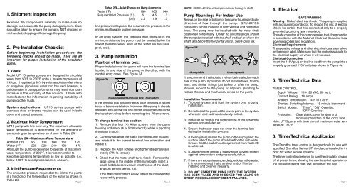
<strong>1.</strong> <strong>Shipment</strong> <strong>Inspection</strong>Examine the components carefully to make sure nodamage has occurred to the pump during shipment. Careshould be taken to ensure the pump is NOT dropped ormishandled; dropping will damage the pump.<strong>2.</strong> <strong>Pre</strong>-<strong>Installation</strong> <strong>Checklist</strong>Before beginning installation procedures, thefollowing checks should be made. They are allimportant for proper installation of the circulatorpump.<strong>1.</strong> Uses:Model UP 15 series pumps are designed to circulatewater from 50°F to 230°F up to a maximum pressure of145 psi. If required, a 50% by volume solution of ethyleneor propylene glycol and water can be used, however, apsi decrease in pump performance may result due to anincrease in the viscosity of the solution. Check withmanufacturer for information regarding suitability ofpumping other fluids.System Applications: UP15 series pumps withstainless steel or bronze volutes can be used in bothopen and closed systems.<strong>2.</strong> Maximum Water Temperature:UP15 pump with line cord only. The maximum allowablewater temperature is determined by the ambient orsurrounding air temperature as shown in Table 2A.Table 2A – Maximum Water TemperatureAmbient (°F) 95 130 140 160 175Water (°F) 230 220 210 190 175Although the pump is designed to operate at maximumwater temperature of 230°F, it is recommended tokeep the operating temperature as low as possible (i.e.below 140°F to avoid precipitation of calcium).3. Inlet <strong>Pre</strong>ssure RequirementsThe amount of pressure required at the inlet of the pumpis a function of the temperature of the water as shown inTable 2B.Table 2B – Inlet <strong>Pre</strong>ssure RequirementsWater (°F) 190 165 140Required Inlet <strong>Pre</strong>ssure (ft.) 5 4.5 3(psi) <strong>2.</strong>2 <strong>1.</strong>9 <strong>1.</strong>3In a pressurized system, the required inlet pressure is theminimum allowable system pressure.In an open system, the required inlet pressure is theminimum distance the pump must be located below thelowest possible water level of the water source (tank,pool, etc.).3. Pump <strong>Installation</strong>Position of terminal box:Proper installation of the pump will have the terminal boxlocated to one side of the pump or the other, with theconduit entry down. See Figure 3A.Figure 3ARecommended Terminal Box OrientationIf the terminal box position needs to be changed, it is bestto do so before installation. However, if the pump is alreadyinstalled, ensure that the line cord is unplugged and closethe isolation valves before removing the Allen screws.To change terminal box position:<strong>1.</strong> Remove the four (4) Allen screws from the pumphousing and stator (4 or 5mm wrench) while supportingthe stator (motor).<strong>2.</strong> Carefully separate the stator from the pump housingand rotate it to the correct terminal box orientation andreseat it.3. Replace the Allen screws and tighten diagonally andevenly (7 ft.-lb. torque).4. Check that the motor shaft turns freely. Remove thelarge screw in the middle of the nameplate, insert asmall flat blade screwdriver into the end of the shaft,and turn gently (see fig. 7a).If the shaft does not turn easily, repeat the disassembly/reassembly process.NOTE: UPS15-42 does not require manual turning of shaft.Pump Mounting: For Indoor UseArrows on the side or bottom of the pump housing indicatedirection of flow through the pump. GRUNDFOScirculators can be installed in both vertical and horizontallines. The pump must be installed with the motor shaftpositioned horizontally. Under no circumstances shouldthe pump be installed with the shaft vertical or where theshaft falls below the horizontal plane. See Figure 3B.Figure 3BAcceptableUnacceptableIt is recommend that isolation valves be installed on eachside of the pump. If possible, do not install elbows, branchtees, and similar fittings just before or after the pump.Provide support to the pump or adjacent plumbing toreduce thermal and mechanical stress on the pump.<strong>Installation</strong> Requirements<strong>1.</strong> Thoroughly clean and flush the system prior to pumpinstallation.<strong>2.</strong> Do not install the pump at the lowest point of the systemwhere dirt and sediment naturally collect.3. Install an air vent at the high point(s) of the system toremove accumulated air.4. Ensure that water does not enter the terminal boxduring the installation process.5. (Open System) Install the pump in the supply line; thesuction side of the pump should be flooded with water.Ensure that the static head requirement from Table 2Bis achieved.6. (Closed System) Install a safety relief valve to protectagainst temperature and pressure build-up.7. If there are excessive suspended particles in the water,it is recommended that a strainer and/or filter beinstalled and cleaned regularly.8. DO NOT START THE PUMP UNTIL THE SYSTEMHAS BEEN FILLED AND CHECKED FOR LEAKS OROTHER POSSIBLE COMPONENT FAILURES.4. ElectricalSAFE WARNINGWarning - Risk of electrical shock - This pump is suppliedwith a grounding conductor. To reduce the risk of electricshock, be certain that it is connected only to a properlygrounded grounding type receptacle.The safe operation of this pump requires that it be groundedin accordance with the National Electrical Code and localgoverning codes and regulations.Electrical RequirementsThe operating voltage and other electrical data are markedon the motor label. Make sure that the motor is suitable forthe electrical supply on which it will be used.Electrical ConnectionInsert the 115V plug on the line cord from the pump into aproperly grounded 115V outlet as shown in Figure 4a.5. Timer Technical DataTIMER CONTROLSupply Voltage: 115-120 VAC, 60 hertzContact Rating: 16 ampsAmbient Temperature: -4°F to 175°FShortest Switching Interval: 15 minute incrementSwitch Modes: “Timer”, “ON” Override,“OFF” OverrideProtection: Clear plastic cover for dust andmoisture protection of the clock face.Note: UP15 pump with timer control maximum water temperature:150°F6. Timer Technical ApplicationThe <strong>Grundfos</strong> timer control is designed only for use withspecified <strong>Grundfos</strong> Series UP circulators installed in indoorhot water service systems.The timer control is designed to turn the circulator on andoff at preset times, allowing the user to select operation ofthe circulator during high use periods of the day.Page 1 Page 2 Page 3 Page 4
7. Timer Operation 9. Limited WarrantySetting and Operating the Timer Controland Starting the PumpNOTE: Before the circulator is started, the system mustbe filled with liquid and vented.<strong>1.</strong> Set the timer switch to the actual time by turning theprogramming ring in the direction of the arrow untilthe timing arrow points to the actual time on the ring.<strong>2.</strong> Switch on the power supply to the circulator and setthe manual switch to the “ON” position. The circulatorwill now start.3. Set the required “ON”/”OFF” times on the programmingring by pushing the programming tabs eitheraway from or toward the center of the ring. Tabspushed away from the center indicate the circulatoris switched ”ON” while tabs pushed toward the centerindicate the circulator is switched “OFF”.Figure 6bPROGRAMMINGRINGTIMING ARROWMANUAL SWITCHPROGRAMMINGTABSFigure 6a5. For continuous operation, set the manual switch tothe “ON” position. To switch the circulator off, set themanual switch to the “OFF” position. The “ON”/”OFF”modes may be used without affecting the function ofeither the programming ring or the timer switch.6. In case of power outage the timer will not keep time.After power has been restored, the correct time ofday must be reset by rotating the programming ringin the direction of the arrow until the timing arrowpoints to the actual time on the ring.8. Failure to OperateWhen the pump is first started, the shaft may rotate slowlyuntil water has fully penetrated the bearings. If the pumpdoes not run, the shaft can be rotated manually. Toaccomplish this, switch off the electrical supply, and closethe isolation valves on each side of the pump. Removethe indicator plug in the middle of the nameplate. Inserta small flat blade screwdriver into the end of the shaft,and gently turn until the shaft moves freely (see Figure7a). Replace and tighten the plug. Open the isolationvalves and wait 2 to 3 minutes for the system pressureto equalize before starting the pump.Figure 7aProducts manufactured by GRUNDFOS PUMPS CORPORATION(GRUNDFOS) are warranted to the original user only to be free of defectsin material and workmanship for a period of 18 months from date ofinstallation, but not more than 24 months from date of manufacture.GRUNDFOS' liability under this warranty shall be limited to repairing orreplacing at GRUNDFOS' option, without charge, F.O.B. GRUNDFOS'factory or authorized service station, any product of GRUNDFOSmanufacture. GRUNDFOS will not be liable for any costs of removal,installation, transportation, or any other charges which may arise inconnection with a warranty claim. Products which are sold but notmanufactured by GRUNDFOS are subject to the warranty provided by themanufacturer of said products and not by GRUNDFOS' warranty.GRUNDFOS will not be liable for damage or wear to products caused byabnormal operating conditions, accident, abuse, misuse, unauthorizedalteration or repair, or if the product was not installed in accordance withGRUNDFOS' printed installation and operation instructions.To obtain service under this warranty, the defective product must be returnedto the distributor or dealer of GRUNDFOS products from which it waspurchased together with proof of purchase and installation date, failure date,and supporting installation data. Unless otherwise provided, the distributoror dealer will contact the GRUNDFOS factory or authorized service stationfor instructions. Any defective product to be returned to the factory or servicestation must be sent freight prepaid; documentation supporting the warrantyclaim and/or a Return Authorization must be included if so instructed.GRUNDFOS WILL NOT BE LIABLE FOR ANY INCIDENTAL ORCONSEQUENTIAL DAMAGES, LOSSES, OR EXPENSES ARISINGFROM INSTALLATION, USE, OR ANY OTHER CAUSES. THERE ARENO EXPRESS OR IMPLIED WARRANTIES, INCLUDINGMERCHANTABILITY OR FITNESS FOR A PARTICULAR PURPOSE,WHICH EXTEND BEYOND THOSE WARRANTIES DESCRIBED ORREFERRED TO ABOVE.Some jurisdictions do not allow the exclusion or limitation of incidental orconsequential damages and some jurisdictions do not allow limitations onhow long implied warranties may last. Therefore, the above limitations orexclusions may not apply to you. This warranty gives you specific legalrights and you may also have other rights which vary from jurisdiction tojurisdiction.<strong>Grundfos</strong> Pumps Corporation17100 W.118th TerraceOlathe, Kansas 66061Telephone: (913) 227-3400Fax: (913) 227-3500<strong>Grundfos</strong> Canada, Inc.2941 Brighton Rd.Oakville, Ontario L6H 6C9Telephone: (905) 829-9533Fax: (905) 829-9512L-UP-TL-018 02/05PRINTED IN USABombas <strong>Grundfos</strong> de Mexico, S.A. de C.V.Boulevard TLC #15, Parque IndustrialStiva AeropuertoC.P. 66600 Apodaca, N.L. MexicoTelephone: 52-81-8144-4000Fax: 52-81-8144-4010<strong>Installation</strong> & Operating InstructionsMainintenance-Ftenance-Free ee Cirirculaculators with th LineineCorord d and Optionaonal Timer Conontrtrol<strong>Shipment</strong> <strong>Inspection</strong>.................... page <strong>1.</strong><strong>Pre</strong>-<strong>Installation</strong> <strong>Checklist</strong>. ............ page <strong>1.</strong>Pump <strong>Installation</strong>. ........................ page <strong>2.</strong>Electrical....................................... page 4.Timer Control Technical Dataand Application. ........................... page 4.Timer Operation. .......................... page 5.Failure to Operate. ....................... page 6.Warranty. ....................................... page 7.4. Set the manual switch to the “TIMER” position. Thecirculator will now start/stop according to the settingsof the programming tabs.Page 5 Page 6


