W1GHZ W1GHZ
W1GHZ W1GHZ
W1GHZ W1GHZ

Create successful ePaper yourself
Turn your PDF publications into a flip-book with our unique Google optimized e-Paper software.
W2IMU feed - bad imitation, by NEC2Figure 6.5-3E-plane0 dB -10 -20 -30H-planeDish diameter = 14.3 λ Feed diameter = 1.43 λFeed Phase Angle90E-plane67.5H-plane4522.50-22.5-45-67.5-900 10 20 30 40 50 60 70 80 90Rotation Angle around specifiedPhase Center = 0 λ beyond aperture908070MAX Possible Efficiency with Phase errorMAX Efficiency without phase error AFTER LOSSES:REAL WORLD at least 15% lowerIlluminationSpilloverFeed Blockage1 dBEfficiency %6050403020102 dB3 dB4 dB5 dB6 dB7 dB8 dB0.250.3 0.4 0.5 0.6 0.7 0.8 0.9Parabolic Dish f/D<strong>W1GHZ</strong> 1998
W2IMU dual-mode horn calculationsA sketch of the W2IMU dual-mode feed is shown in Figure 6.5-4. The input circular waveguideflares out to a larger output section. Only the TE mode will propagate in the smaller input11waveguide, but both the TE and TM modes can propagate in larger output waveguide. Our goal is1111for the relative phases and amplitudes of the TE and TM modes to cancel the electric field at the1111aperture boundary.The electric field for the TE mode in a circular waveguide 5 is shown in Figure 6.5-5a at an instant of11peak voltage. The desired TM mode that will result in field cancellation at the aperture is shown in11Figure 6.5-5b; note how the field arrows for the two modes are in opposite directions at the top andbottom of the waveguide, so that they cancel. In the center of the guide, the field arrows for the twomodes point in the same direction, so that the fields will add together. The result is a stronger electricfield in the center of the aperture and no field at the edges; this is analogous to a smaller aperture, sothat the resulting radiation pattern in the E-plane will be broader and match the H-plane pattern.The length of the output section controls the relative phase of the two modes, while the flare anglecontrols the relative amplitude of the two modes. To achieve cancellation of current in the rim of thehorn and thus minimize lobes, we must find the right combination of flare angle and output phasingsection length.
6.5.2 W2IMU dual-mode feed examplesAs examples of actual dual-mode feeds, we will start with three versions of the W2IMU feed whichhave been published in Britain, then examine a dual-mode feed for 47 GHz by G0IVA, and finallylook at larger dual-mode feedhorns for offset dishes. The British versions attempt to achieve properdimensions using available materials; making some compromises in the dimensions. I modeled themusing NEC2 in order to evaluate performance — we will see if the compromise dimensions aresuccessful.The first example is a 10 GHzversion described by G3PHO 7 usingBritish plumbing fittings, shown inthe photo in Figure 6.5-7. Theperformance plot in Figure 6.5-8shows a clean pattern and excellentdish efficiency for an f/D around0.6, a bit smaller than the DSSdishes require, but very usable. Theequivalent f/D for the DSS dishes,and many other offset dishes, isaround 0.68; this feed would providevery slight under-illumination,but the efficiency would still beexcellent. Perhaps we can find away to import some of these plumbingfittings into the USA. Thephase center of the feed is at thecenter of the aperture. Peter hasdone a good job with this version.The second example is the 5.7 GHz “plumbers delight” by G0HNW 8 . Paul states that the aperturewith the available plumbing is a bit small for an offset dish. The plot in Figure 6.5-9 bears this out,showing best efficiency for an f/D of about 0.4. In fact, the aperture diameter is 1.21λ, which issmaller than the cutoff wavelength for the TM mode, so it is unlikely that this feed supports dualmodeoperation. Further evidence is the radiation pattern with several significant sidelobes, including11one rather large one. I suspect that it is behaving more like a simple coffee-can feed. Despite thesidelobes and lack of dual-mode operation, calculated efficiency is very high, so it would be quite agood feed for f/D in the 0.45 to 0.5 range. The phase center is very close to the center of the aperture.However, for a dual-mode feed to provide good illumination of an offset reflector, a largeraperture diameter around 1.5λ, or about 3 inches at 5760 MHz, would be required.
Feed Radiation PatternG3PHO 10 GHz dual-mode feedhorn, by NEC2Figure 6.5-8E-plane0 dB -10 -20 -30H-planeDish diameter = 16 λ Feed diameter = 0.1 λFeed Phase Angle90E-plane67.5H-plane4522.50-22.5-45-67.5-900 10 20 30 40 50 60 70 80 90Rotation Angle around specifiedPhase Center = 0.06 λ inside apertureParabolic Dish Efficiency %9080706050403020MAX Possible Efficiency with Phase errorMAX Efficiency without phase error AFTER LOSSES:REAL WORLD at least 15% lowerIlluminationSpilloverFeed Blockage1 dB2 dB3 dB4 dB5 dB6 dB7 dB8 dB100.250.3 0.4 0.5 0.6 0.7 0.8 0.9Parabolic Dish f/D<strong>W1GHZ</strong> 1998
Although this version is not optimized for an offset dish, Paul reports a significant improvementcompared to a triband feed. Since the triband feed is basically a dipole feed, which gives best resultswith very deep dishes, we would expect performance like Figure 6.2-1. At the high equivalent f/Dneeded to feed an offset dish, efficiency is very low. In addition, the triband feed has been shown tobe rather lossy at 5.7 GHz, further reducing efficiency. Almost anything is better than a triband feedfor an offset dish at 5.7 GHz.The third British dual-mode example is a 24 GHz version by G8ACE 9 . The plumbing fitting used inthis version provides an aperture of 22mm, or1.75λ, which is about right for an offset dish. The inputwaveguide is 10mm pipe, and there are apparently no plumbing reducers from 22mm to 10mm.Instead, a reducer to an intermediate size of 15mm is used, so that there are two flare sections with alength of 15mm waveguide between them. This combination makes it difficult to predict how the twomodes will end up, so I calculated the radiation pattern using NEC2. The results are shown in Figure6.5-10. The E-plane pattern has large sidelobes and a null at about 30º off-axis, suggesting thatmodes do not have the desired relationship at the aperture. As a result, calculated efficiency is mediocre,and the phase center is displaced about 0.4λ inside the horn.Rapid changes in amplitude, like the null in the E-plane pattern, areusually accompanied by rapid phase changes. This is clearly illustratedin Figure 6.5-10 — the feed phase plot in the upper rightexhibits a large change in phase around 30º off-axis. The effect ondish efficiency is evident in the lower graph, showing significantphase error at larger illumination angles.We can deduce from this last example that a single flare sectionoffers much better mode control for dual-mode operation. At 24GHz, dimensions are small enough so that it should be easy tofabricate a short conical section. The HDL_ANT program willprepare a paper template for any desired flare dimensions.All three examples thus far are attempts at different frequencies tofabricate a W2IMU dual-mode feed using available materials. A 47GHz feedhorn 10 by G0IVA uses the opposite approach — it ismachined from solid brass. Figure 6.5-11 shows the feed attachedto a DB6NT transverter; this combination plus an offset dish hasbeen successful over distances >100km. G3PHO sent me thesketch shown in Figure 6.5-12; the dimensions are very close tobeing a scaled-down copy of the W2IMU 1296 MHz horn. Theonly difference is that the large diameter section is 0.04 wavelengthstoo long — and the result is slightly larger sidelobes. Calculatedefficiency from the NEC2 radiation patterns is not harmed,as shown in Figure 6.5-13. The discrepancy of 0.04 wavelengths isabout 0.012 inches - about 10 strokes with a file!
Feed Radiation PatternG8ACE dual-mode feed for 24 GHz, by NEC2Figure 6.5-10E-plane0 dB -10 -20 -30H-planeDish diameter = 18 λ Feed diameter = 1.8 λFeed Phase Angle90E-plane67.5H-plane4522.50-22.5-45-67.5-900 10 20 30 40 50 60 70 80 90Rotation Angle around specifiedPhase Center = 0.4 λ inside apertureParabolic Dish Efficiency %9080706050403020MAX Possible Efficiency with Phase errorMAX Efficiency without phase error AFTER LOSSES:REAL WORLD at least 15% lowerIlluminationSpilloverFeed Blockage1 dB2 dB3 dB4 dB5 dB6 dB7 dB8 dB100.250.3 0.4 0.5 0.6 0.7 0.8 0.9Parabolic Dish f/D<strong>W1GHZ</strong> 1998
Feed Radiation PatternG0IVA 47 GHz dual-mode feedhorn, by NEC2Figure 6.5-13E-plane0 dB -10 -20 -30H-planeDish diameter = 13 λ Feed diameter = 1.3 λFeed Phase Angle90E-plane67.5H-plane4522.50-22.5-45-67.5-900 10 20 30 40 50 60 70 80 90Rotation Angle around specifiedPhase Center = 0.04 λ beyond apertureParabolic Dish Efficiency %9080706050403020MAX Possible Efficiency with Phase errorMAX Efficiency without phase error AFTER LOSSES:REAL WORLD at least 15% lowerIlluminationSpilloverFeed Blockage1 dB2 dB3 dB4 dB5 dB6 dB7 dB8 dB100.250.3 0.4 0.5 0.6 0.7 0.8 0.9Parabolic Dish f/D<strong>W1GHZ</strong> 1998
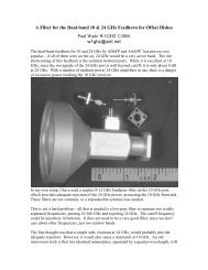
Most of the offset-fed dishes that I have found require an illumination angle equivalent to an f/D ofabout 0.7. The calculated efficiency for the large W2IMU feedhorn in Figure 6.5-2 is very high withbest f/D around 0.8, so I thought that a slightly smaller aperture would work well for an offset feed.The optimum diameter for 10 GHz is between standard plumbing sizes, larger than 1 ½” and smallerthan 2” copper pipe, so I had to search for an intermediate size. At a scrap-metal yard I located alength of brass pipe with an i.d. of 1.85”, or 1.63λ. Using the equations seen earlier in this section,I calculated a flare half-angle of 27.4° and an output section length (C) of 2.8λ, or 3.19 inches at10.368 GHz.The radiation patterns calculated by NEC2 for these dimensions, plotted in Figure 6.5-14, show lowsidelobes and excellent calculated efficiency. I made a template for the flare section usingHDL_ANT and soldered it to a length ofthe brass pipe, with standard ¾” copperpipe as the input waveguide. The finishedhorn is shown in Figure 6.5-15, alongwith an even larger version describedbelow. Measured performance using sunnoise is also excellent: on a one-meteroffset dish, the efficiency was slightlyhigher than measured with the rectangularfeedhorn of Figures 6.4-11 and 6.4-12.Since the rectangular feedhorn has demonstratedhigh measured efficiency andexcellent field performance, achieving
Feed Radiation PatternW2IMU large dual-mode feed, 1.63λ diameter, by NEC2Figure 6.5-14E-plane0 dB -10 -20 -30H-planeDish diameter = 15.8 λ Feed diameter = 0.5 λFeed Phase Angle90E-plane67.5H-plane4522.50-22.5-45-67.5-900 10 20 30 40 50 60 70 80 90Rotation Angle around specifiedPhase Center = 0 λ beyond apertureParabolic Dish Efficiency %9080706050403020MAX Possible Efficiency with Phase errorMAX Efficiency without phase error AFTER LOSSES:REAL WORLD at least 15% lowerIlluminationSpilloverFeed Blockage1 dB2 dB3 dB4 dB5 dB6 dB7 dB8 dB100.250.3 0.4 0.5 0.6 0.7 0.8 0.9Parabolic Dish f/D<strong>W1GHZ</strong> 1998
higher calculated and measured efficiency with the dual-mode feed is an accomplishment. In fact,efficiency with the dual-mode feed measured 1% higher using circular polarization than with linearpolarization — a capability you can’t get with a rectangular horn.I also have another offset dish, 0.8m diameter, which requires a narrower illumination angle equivalentto f/D = 0.8, just right for the original large W2IMU dual-mode horn. The closest material Icould find to the desired 1.88λ diameter (dimension B)was standard 2” copper pipe, with an i.d. of2.04” or 1.79λ at 10.368 GHz (I had to buy a full ten-foot length, if anyone needs some!). Thecalculated dimensions for this aperture diameter are: flare half-angle = 24.9° and output sectionlength (C) = 3.52λ, or 4.01 inches at 10.368 GHz. Figure 6.5-16 is a reminder how the flare angledecreases and the length increases with increasing diameter.FlareHalf-AngleInputWaveguideABCW2IMU DUAL-MODE HORNFigure 6.5-16The larger offset dual-mode horn also exhibits excellent performance, both from the NEC2 calculationsplotted in Figure 6.5-17 and from sun noise measurements on the 0.8 meter dish. If it wasn’tapparent from Figure 6.5-15, it is worth noting that these two horns are not precision fabrications;they were built in my basement with hand tools and a torch. The smaller one still has a few solderlumps inside that need to be filed down. Yet they are both good performers — so don’t be afraid tobuild your own!
Feed Radiation PatternW2IMU dual-mode feed, 1.79λ diameter, by NEC2Figure 6.5-17E-plane0 dB -10 -20 -30H-planeDish diameter = 17.9 λ Feed diameter = 1.79 λFeed Phase Angle90E-plane67.5H-plane4522.50-22.5-45-67.5-900 10 20 30 40 50 60 70 80 90Rotation Angle around specifiedPhase Center = 0 λ beyond apertureParabolic Dish Efficiency %9080706050403020MAX Possible Efficiency with Phase errorMAX Efficiency without phase error AFTER LOSSES:REAL WORLD at least 15% lowerIlluminationSpilloverFeed Blockage1 dB2 dB3 dB4 dB5 dB6 dB7 dB8 dB100.250.3 0.4 0.5 0.6 0.7 0.8 0.9Parabolic Dish f/D<strong>W1GHZ</strong> 1998
Feed Radiation Pattern2" plumbing adapter makes poor W2IMU feed, by NEC2Figure 6.5-18E-plane0 dB -10 -20 -30H-planeDish diameter = 10 λ Feed diameter = 1 λFeed Phase Angle90E-plane67.5H-plane4522.50-22.5-45-67.5-900 10 20 30 40 50 60 70 80 90Rotation Angle around specifiedPhase Center = 0.8 λ inside apertureParabolic Dish Efficiency %9080706050403020MAX Possible Efficiency with Phase errorMAX Efficiency without phase error AFTER LOSSES:REAL WORLD at least 15% lowerIlluminationSpilloverFeed Blockage1 dB2 dB3 dB4 dB5 dB6 dB7 dB8 dB100.250.3 0.4 0.5 0.6 0.7 0.8 0.9Parabolic Dish f/D<strong>W1GHZ</strong> 1998