S3.25 Leg Press Station - Precor
S3.25 Leg Press Station - Precor
S3.25 Leg Press Station - Precor
- No tags were found...

Create successful ePaper yourself
Turn your PDF publications into a flip-book with our unique Google optimized e-Paper software.
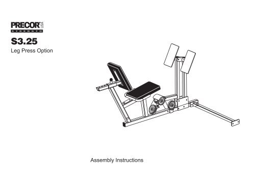
<strong>S3.25</strong> <strong>Leg</strong> <strong>Press</strong> Option Assembly Instructions1Before You BeginThank you for purchasing the <strong>Leg</strong> <strong>Press</strong> Option foryour <strong>Precor</strong> equipment. This option will add a newdimension to your strength-training regimen. Forproper installation, please read this guide thoroughlyand follow the assembly instructions.Unpacking the EquipmentThe <strong>Leg</strong> <strong>Press</strong> Option is carefully tested and inspectedbefore shipment. <strong>Precor</strong> ships the unit in several piecesthat require assembly. Two people are required toassemble this equipment. Ask for assistance duringthe assembly process.• Review the Installation Requirements on thenext page.• Carefully unpack the pieces and lay them onthe floor near the place where you plan to usethe equipment.If any items are missing, contact the dealer from whomyou purchased the unit or call 1-800-4-PRECOR to findthe dealer nearest you.Before You Beginpage 4
<strong>S3.25</strong> <strong>Leg</strong> <strong>Press</strong> Option Assembly Instructions2 PreparationsCAUTION: To set up this equipment, you will needassistance. Do not attempt assembly by yourself.You must review and follow the instructions in thisguide. If you do not assemble and use the <strong>Leg</strong> <strong>Press</strong>Option according to the following guidelines, you couldvoid the <strong>Precor</strong> limited warranty.Required ToolsYou need to obtain these tools before assemblingthe unit:❑❑❑❑❑❑❑❑¾-inch socket wrench¾-inch box-end wrench⁹⁄₁₆-inch socket wrench⁹⁄₁₆-inch box-end wrenchTwo adjustable pliers or crescent wrenchesStandard set of metric Allen wrenchesUtility knife or scissorsMeasuring tapeInstallation RequirementsFollow these installation requirements whenassembling the unit:• Fill out and mail the limited warranty card.The warranty card is found on the back cover ofthis guide.• Set up the <strong>Leg</strong> <strong>Press</strong> Option on a solid, flatsurface. A smooth, flat surface under the unit helpskeep it level. A level unit has fewer malfunctions.• Provide ample space around the machine.Open space around the machine allows for easieraccess.• Insert all bolts in the same direction. Foraesthetic purposes, insert all the bolts in the samedirection unless specified (in text or illustrations) todo otherwise.• Leave room for adjustments. Tighten fastenerssuch as bolts, nuts, and screws, so that the unit isstable, but leave room for adjustments. Do not fullytighten fasteners until instructed in the assemblysteps to do so.Assembly Tips• A 6-inch scale is provided at the bottom of everyassembly instruction page. Use this scale to identifythe correct size bolts and spacers. The head of abolt is not used in measuring the length of a bolt.To find out the length of a particular bolt, measure itsshank (the long, narrow part beneath the head). Referto the following diagram.• Read all caution notes on each page beforecompleting that step.Bolt headBolt threadsShankTo determine thelength of a bolt,measure its shank.• Some pieces have extra holes that you will not use.Use only those holes indicated in the instructionsand illustrations.• While you may be able to assemble the <strong>Leg</strong> <strong>Press</strong>Option by using the illustrations only, refer to thetext for important safety cautions and notes.Preparationspage 5
<strong>S3.25</strong> <strong>Leg</strong> <strong>Press</strong> Option Assembly Instructions3AssemblyInstructionsAssembly of the <strong>Leg</strong> <strong>Press</strong> Option takes professionalinstallers about 1 hour to complete. If this is the first timeyou have assembled this type of equipment, plan onsignificantly more time.Professional installers are highly recommended!CAUTION: Obtain assistance! Do not attemptto assemble the <strong>Leg</strong> <strong>Press</strong> Option by yourself.Because of the weight and size of the <strong>Leg</strong> <strong>Press</strong>Option, you could be injured or damage theequipment. Review the Installation Requirementson page 5 before proceeding.The <strong>Leg</strong> <strong>Press</strong> Option comes in one box. It can beinstalled on either the <strong>S3.25</strong> or S3.45 <strong>Precor</strong> StrengthTraining Equipment. Note that the location where youattach the Cross Brace to the Seat Frame differs.As you read through the assembly instructions, besure that you are using the correct mounting holes foryour unit.Be careful to assemble the components in thesequence presented in this guide.Note: As with any assembled part, proper alignment andadjustment is critical. While tightening the fasteners, besure to leave room for adjustments. Do not fully tighten thefasteners until instructed to do so.1 2 3 4 5 6Assembly Instructionspage 6
<strong>S3.25</strong> <strong>Leg</strong> <strong>Press</strong> Option Assembly Instructions1. Remove the ShroudImportant: For ease of assembly, the fasteners andhardware for each step are labeled and packaged inseparate bags.Note: If you are assembling the <strong>Leg</strong> <strong>Press</strong> Option alongwith your <strong>S3.25</strong>, go directly to Step 2.Top BeamBefore you can attach the <strong>Leg</strong> <strong>Press</strong> Option to the unit, youmust remove the Shroud.A. Remove the Shroud by loosening and removingsix 2¾-inch boltssix washerssix locknutsB. Pull the Shroud away from the <strong>S3.25</strong> and lay it andits fasteners on the floor in a secure place.Note: The top of the Shroud has a notch in it tohelp you clear the Top Beam fastener.Notch in Shroud fitsaround Top BeamfastenerA6 - 2¾" bolts6 - washers6 - locknutsBRemove Shroud1 2 3 4 5 6Step 1. Remove the Shroudpage 7
<strong>S3.25</strong> <strong>Leg</strong> <strong>Press</strong> Option Assembly Instructions2. Attach the Cross Brace to the<strong>S3.25</strong>Note: If you are assembling the <strong>Leg</strong> <strong>Press</strong> Option alongwith the <strong>S3.25</strong>, you should complete Step 10 in the<strong>S3.25</strong> Assembly and Maintenance Guide beforeattaching the Cross Brace.A. Align the Cross Brace to the <strong>S3.25</strong> Rear Uprightand secure it usingtwo 3-inch boltsfour washerstwo locknutsWrench tighten.A2 - 3" bolts4 - washers2 - locknutsCross Brace1 2 3 4 5 6Step 2. Attach the Cross Brace to the <strong>S3.25</strong>page 8
<strong>S3.25</strong> <strong>Leg</strong> <strong>Press</strong> Option Assembly Instructions3. Assemble the FrameA. With someone helping you, lift the Seat Frameupright. Have your assistant hold it in place while youattach the Cross Brace in the next step.B. Attach the Cross Brace to the holes found at thefront of the Seat Frame usingtwo 3-inch boltsfour washerstwo locknutsWrench tighten.CBackpadSupportBackpadSupportPop PinImportant: A label on the Seat Frame indicates themounting holes you must use to attach the CrossBrace to the <strong>S3.25</strong> <strong>Leg</strong> <strong>Press</strong> Option.C. Slide the Backpad Support into the Seat Frame,locking it in place with the Pop Pin.ASeat FrameHave an assistant holdthe Seat Frame stableand upright while youattach the Cross BraceCross BraceLabel indicates mountinglocation for the <strong>S3.25</strong>B2 - 3" bolts4 - washers2 - locknuts1 2 3 4 5 6Step 3. Assemble the Framepage 9
<strong>S3.25</strong> <strong>Leg</strong> <strong>Press</strong> Option Assembly InstructionsD. Assemble the Footrest by resting the Pivot Armon the Rubber Bumper. Make sure that the redarrow on the back of the Footrest points towardthe ceiling.E2 - large ½" x 3¼" bolts4 - ½" diameter washers2 - large ½" lock nutsE. Attach the Footrest to the Pivot Arm and PivotTube usingtwo large ½-inch by 3-¼-inch boltsfour ½-inch-diameter washerstwo large ½-inch locknutsWrench tighten enough to allow free movement ofthe Pivot Arm.F2 - 3" bolts4 - washers2 - locknutsF. Attach the Handle to the Seat Frame usingtwo 3-inch boltsfour washerstwo locknutsWrench tighten.FootrestPivot ArmHandlePop PinFootrestSeat FrameRed Arrow LabelPivot ArmPivot TubeRubber BumperDRest the Pivot Arm on theRubber Bumper1 2 3 4 5 6Step 3. Assemble the Frame, Continuedpage 10
<strong>S3.25</strong> <strong>Leg</strong> <strong>Press</strong> Option Assembly Instructions4. Assemble the Seat PadsA. Attach one of the Seat Pads to the Seat BracketSupport usingtwo 1¼-inch boltstwo washersWrench tighten.Seat Padused as aback restSeat Bracket SupportBLift the PopPin to slidethe back restB. Lift the Pop Pin and slide the Seat Pad out of theway to assemble the other Seat Pad.C. Attach the remaining Seat Pad to the Seat Frameusingtwo 3-inch boltstwo washersWrench tighten.Note: Make sure that the seams on the Seat Padsface down toward the frame.HandleA2 - 1¼" bolts2 - washersNote: If you are assembling the <strong>Leg</strong> <strong>Press</strong> Option andthe <strong>S3.25</strong> simultaneously, return to Step 11 in the<strong>S3.25</strong> Assembly and Maintenance Guide now.Seat FrameSeat PadC2 - 3" bolts2 - washers1 2 3 4 5 6Step 4. Assemble the Seat Padspage 11
<strong>S3.25</strong> <strong>Leg</strong> <strong>Press</strong> Option Assembly Instructions5. Route the CableAs you route the Cable through the pulleys on the <strong>Leg</strong><strong>Press</strong> Option, wrench tighten the fasteners on eachpulley as you go. Make sure that the Cable slides freelyalong the pulley (and beneath the cable retainer). Makesure that you are using the correct Cable before youtighten the fasteners.A. Attach the barrel end of Cable 40538-101 to theSeat Frame usingone 4-inch boltone washerone locknutWrench tighten so that the barrel end of the Cablerotates freely.B. Loosen all the fasteners that attach the pulleys tothe Seat Frame.C. Push the Pivot Arm forward so that the pulleys areeasily accessible.D. Route the Cable around the pulley inside the PivotArm Cover that is on the same side as the barrelend of the Cable (see illustration). The Cableshould slide along the pulley beneath the cableretainer. Wrench tighten this pulley’s fasteners.E. You may need to slide the bolt out of the Pivot ArmCover to wrap the Cable around the pulley.F. Continue to route the Cable around the pulleys asshown in the illustration. Make sure that the Cableslides freely along the pulleys (and beneath thecable retainers) before you wrench tighten theirfasteners.G. Wrap the Cable around the 4½-inch pulley (andbeneath its cable retainer) that is attached to theCross Brace. Wrench tighten.PivotArmPush the PivotArm forward1 - 4" bolt1 - washer1 - locknutCALoosen the pulleyB fastenersNote: The Seat Pad is not shown.Pivot ArmDEFSeat FrameCable 40538-1011 2 3 4 5 6GWrap the Cable around the4½" pulley attached to theCross BraceStep 5. Route the Cablepage 12
<strong>S3.25</strong> <strong>Leg</strong> <strong>Press</strong> Option Assembly Instructions6. Assemble the Cable andPulleysYou can identify Cables by the white numbers placed atthe end of the Cable.A. Place <strong>Leg</strong> <strong>Press</strong> Option Cable 40538-101 between acable retainer and one 3½-inch pulley. Attach thepulley to the Lower Pulley Bracket located at thebase of the Rear Upright usingone 2-inch bolttwo washersone locknutWrench tighten.B. From the Top Beam, remove the surgical tube andits fasteners.Note: Discard the fastenersone 3¼-inch boltone one-inch barrel spacertwo washersone locknutCable RetainerRear UprightAttach thisend to theCable TreeCable 40538-1013½" PulleyThis end isattached to the<strong>Leg</strong> <strong>Press</strong>A1 - 2" bolt2 - washers1 - locknutNote that no pulley isattached to this bolt holeLower Pulley BracketSurgicalTubeB Discard1 - 3¼" bolt1 - 1" barrelspacer2 - washers1 - locknutSurgicalTubeCable Tree1 2 3 4 5 6Step 6. Assemble the Cable and Pulleyspage 13
<strong>S3.25</strong> <strong>Leg</strong> <strong>Press</strong> Option Assembly InstructionsC. Reattach the end of the original Surgical Tube fromthe Cable Tree to its prior location and place the newSurgical Tube that came with the <strong>Leg</strong> <strong>Press</strong> Optionto the outside of the Top Beam usingone 4-inch bolttwo washerstwo ½-inch barrel spacersone locknutWrench tighten.CNew SurgicalTube1 - 4" bolt2 - washers2 - ½" barrel spacers1 - locknutD. Place the ball-end of <strong>Leg</strong> <strong>Press</strong> Option Cable 40538-101 up through the Cable Tree and placeit securely in the U-clip.E. Remove the buttonhead bolt and nylock nut fromthe U-clip.F. Attach the end of the original surgical tube to theCable Tree using the 1¼-inch buttonhead bolt andthin nylock nut removed in Step 6E. Wrench tighten.Note: If you are assembling the <strong>Leg</strong> <strong>Press</strong> Option andthe <strong>S3.25</strong> simultaneously, go to Step 21 in the <strong>S3.25</strong>Assembly and Maintenance Guide now.1 - 1¼" button head bolt1 - thin nylock nutEOriginalSurgical TubeCable TreeNew SurgicalTubeU-clipDAttach ballendof Cableto U-clipCable Tree Cable 40538-101(from <strong>Leg</strong> <strong>Press</strong>)1 2 3 4 5 6Step 6. Assemble the Cable and Pulleys, Continuedpage 14
<strong>S3.25</strong> <strong>Leg</strong> <strong>Press</strong> Option Assembly Instructions7. Replace the ShroudA. Pick up the Shroud and fasteners from the locationwhere you left them in Step 4B.Top BeamB. Replace the Shroud by realigning the mountingholes and insertingsix 2¾-inch boltssix washerssix locknutsWrench tighten.Notch in Shroud fitsaround Top BeamfastenerAReplace ShroudB6 - 2¾" bolts6 - washers6 - locknuts1 2 3 4 5 6Step 7. Replace the Shroudpage 15
<strong>S3.25</strong> <strong>Leg</strong> <strong>Press</strong> Option Assembly Instructions4 AdjustmentsAfter the <strong>Leg</strong> <strong>Press</strong> Option is assembled, you shouldcheck the Cables for proper tension. These are someobvious signs that cable problems exist:✔✔✔Excess slack exists in the Cable.The Top Cap Weight does not rest squarely on theWeight Stack.The Cable rubs the inside edges of the pulleys.Top Cap WeightTop WeightWeight PinACAUTION: Take the time to perform the followingsteps. If the Cables do not havethe proper tension, you could damage themachine and void the <strong>Precor</strong> Limited Warranty.Note: To adjust the Selector Stem, refer to the<strong>S3.25</strong> Assembly and Maintenance Guide.1. Stretch the CableA. Sometimes a new cable must be stretched so thatthe Top Cap Weight rests on the Weight Stack. Tolengthen the Cable, insert the Weight Pin at acomfortable weight level.B. Push up on the Chest <strong>Press</strong> Arms, and then slowlylower them.C. Make sure the Top Cap Weight rests squarely onthe Weight Stack. If it does, no more adjustmentsare needed, and the <strong>Leg</strong> <strong>Press</strong> Option is ready touse. If the Top Cap Weight does not rest on the TopChest <strong>Press</strong> Arms1 2 3 4 5 6BCTop CapWeightAdjustmentspage 16
<strong>S3.25</strong> <strong>Leg</strong> <strong>Press</strong> Option Assembly InstructionsWeight then further adjustments are needed.Continue with steps 2 and 3.2. Rotate the Cam WasherIf the Top Cap Weight does not rest on the Top Weight,you must make further adjustments.A. Remove excess tension from the Cable by placingthe Weight Pin into the Selector Stem just under theTop Cap Weight.B. To tighten or loosen the Cable tension, rotate theCam Washer.C. Look to see that Top Cap Weight rests squarely onthe Weight Stack. If it does, no more adjustments areneeded and the <strong>Leg</strong> <strong>Press</strong> Option is ready to use. Ifthe Top Cap Weight does not rest on the TopWeight, then further adjustments are needed.Continue with step 3.Top CapWeightATop WeightWeight PinBRotate theCam WasherTop CapWeightC1 2 3 4 5 6Step 2. Rotate the Cam Washerpage 17
<strong>S3.25</strong> <strong>Leg</strong> <strong>Press</strong> Option Assembly Instructions3. Adjust the Rubber Bumper onthe <strong>Leg</strong> <strong>Press</strong> OptionIf the Top Cap Weight still does not rest on the TopWeight, you can make one final adjustment.A. If the Cable tension still needs adjusting, push thePivot Arm up so that you can adjust the RubberBumper on the <strong>Leg</strong> <strong>Press</strong> Option.B. Rotate the Rubber Bumper up or down to tighten orloosen the Cable tension.Important: Tighten the locknut against the bracketafter you have properly adjusted the Cable tension.C. Check the weights. Move the Weight Pin to eachWeight and Selector Stem location and replace theWeight Pin in the Weight Stack.With the slack removed from the Cables, you are nowready to use the <strong>Leg</strong> <strong>Press</strong> Option. Thank you forchoosing <strong>Precor</strong> Strength-Training Equipment.Note: For maintenance instructions, refer to your <strong>S3.25</strong>Assembly and Maintenance Guide.BAAdjust theRubber BumperPush the Pivot Arm up to adjustthe Rubber BumperRubber BumperCWeight PinBracketLocknut1 2 3 4 5 6Step 3. Adjust the Rubber Bumper on the <strong>Leg</strong> <strong>Press</strong> Optionpage 18
Residential Equipment Limited Warranty<strong>Precor</strong> Incorporated warrants that all new <strong>Precor</strong> products are free of manufacturing defects inworkmanship and materials. Parts repaired or replaced under the terms of this warranty will bewarranted for the remainder of the original warranty period only. This warranty becomes effectiveat the invoice date of the original purchase.Elliptical Fitness Crosstrainers and Motorized Treadmills (excluding EFX5.17 andTreadmills: 9.2 and 9.4 series) — Labor is covered for one year, parts are covered for five yearsplus a lifetime frame weld warranty covering parts-only repair or replacement parts. (Labor is notcovered on frame replacement after one year.)Products (StretchTrainer, Strength Equipment — formerly Pacific Fitness) other thanElliptical Fitness Crosstrainer and Motorized Treadmills (except options)StretchTrainer — Labor is covered for a period of 90 days, parts are covered for a period of one yearplus a lifetime frame weld warranty covering parts-only repair or replacement parts. (Labor is not covered onframe replacement after one year.)Pacific Fitness Branded Strength Products and <strong>Precor</strong> Strength Products S3.xxThis is a parts only warranty. Labor costs are not covered.1. Frame & Welds: Defective parts pertaining to frame structure, including all welded assemblyparts, will be warranted for Lifetime.2. Bearings, Guide rods, Cams, Pulleys, Belts, Cables, Hand grips, and Miscellaneous parts will bewarranted for a period of three years. Note that for the <strong>Precor</strong> Strength Products S3.xx, andthe Pacific Fitness Solana and Zuma, the warranted period is five years.3. Upholstery will be warranted for a period of one year. A three month warranty applies toNaugahyde upholstery for Pacific Fitness Branded Strength Products only.Return Policy: Proof of purchase is required to determine whether service on a <strong>Precor</strong> Strength Product/Pacific Fitness Product during its warranty period will commence. Claims should be made to the dealerfrom whom you purchased the product. The purchaser is responsible for all transportation and insurancecosts on returned or replaced equipment or parts. The purchaser also assumes any costs associated withthe disassembling or reassembling of the replacement parts. WARRANTY BECOMES VOID IF PRECORFINDS THE DEFECT A RESULT OF INCORRECT INSTALLATION, MISUSE, LACK OF PROPER MAINTE-NANCE OR ANY MODIFICATION NOT APPROVED BY PRECOR.Options / Accessories / Battery-powered or Self-Operated DevicesMany options or accessories have components that are connected internally or mounted insidethe electronic console. The following guidelines determine the warranty for these components. Ifthe internal components are installed by the factory or by an authorized dealer as part of theoriginal sale and delivery, they have a warranty that is identical to the warranty of the equipmentin which they are connected or mounted. If the internal components are not installed by thefactory or by an authorized dealer as part of the original sale and delivery, they have a 90 daysparts and labor limited warranty. All components that are not internally connected have a 90 daysparts only limited warranty. Satisfactory proof of purchase is required in all cases.PRECOR'S SOLE LIABILITY IS LIMITED TO REPAIR OR REPLACEMENT OF PARTS ACCORDING TOTHE TERMS AND CONDITIONS OF THESE LIMITED WARRANTIES, AND ANY IMPLIED WARRANTIESOF MERCHANTABILITY OR FITNESS FOR A PARTICULAR PURPOSE ARE LIMITED TO THE DURATIONOF THE ABOVE WRITTEN WARRANTIES. IN NO EVENT WILL PRECOR OR THE SELLING DEALER BELIABLE FOR INCIDENTAL OR CONSEQUENTIAL DAMAGES SUCH AS INCONVENIENCE, COMMERCIALLOSS, LOST PROFITS OR DAMAGE TO OTHER PROPERTY.Some states do not allow the exclusion or limitation of incidental or consequential damages, so the abovelimitation may not apply to you. This warranty gives you specific legal rights, and you may also have otherrights which vary from state to state.Keep this for your records. Purchased From:Phone Number:Product/Model:Serial #:Effective 01 August 2001P/N 36287-108ConditionsThis warranty is valid only in accordance with theconditions set forth below.1. Warranty applies to the <strong>Precor</strong> product only whileA) it remains in the possession of the originalpurchaser and proof of purchase is demonstrated,B) it has not been subjected to accident, misuse,abuse, improper service, or non-<strong>Precor</strong> modificationand C) claims are made within the warranty period.2. Warranty of all <strong>Precor</strong> products applies to residentialuse only (unless specifically stated by the factory, inwriting, to be warranted for commercial use) and is voidwhen products are used in a non-residential environmentor installed in a country other than where sold.3. This warranty does not cover damage or equipmentfailure caused by residential wiring not in compliancewith electrical codes or <strong>Precor</strong> owner’s manualspecifications, or failure to provide reasonable andnecessary maintenance as outlined in the owner'smanual.4. During the labor period <strong>Precor</strong> compensatesServicers for warranty trips within their normalservice area to repair motorized treadmills andelliptical fitness crosstrainers at the customer’slocation. You may be charged a trip charge outsidethe service area, or for on-site warranty repairs, orfor on-site warranty repairs of strength products,within the service area.5. <strong>Precor</strong> Limited Warranty service may be obtainedby contacting the authorized dealer from whereyou purchased the equipment or by contacting a<strong>Precor</strong> Factory Authorized Service Center, or bycalling 1-800-4-PRECOR (1-800-477-3267).6. Except in Canada, <strong>Precor</strong> does not pay labor outsidethe United States. Equipment limited warranty isvoid when equipment is installed in a country otherthan where sold. For specific warranty details,contact a local <strong>Precor</strong> dealer.This Limited Warranty shall not apply to:1. Software (PROM) limitations or corrections.2. Batteries or other consumables, or cosmeticitems, grips, seats, labels, or wheels.3. Repairs performed on <strong>Precor</strong> equipment missing aserial number or with a serial tag that has been alteredor defaced.4. Service calls to correct installation of the equipmentor instruct owners on how to use the equipment.5. Pick-up, delivery, or freight charges involved with repairs.6. Any labor costs incurred beyond the applicable laborwarranty period.Please fill out the Warranty Registration andmail it to <strong>Precor</strong>.Please detach and return this portion.Purchaser's Signature ____________________________________________________________Serial #Serial number is located on the shipping box and on the product.City State Zip Code–Purchased FromCity State Zip Code–AddressPhone Number–▼Contact PersonMr.Ms.Name of FacilityThe undersigned hereby acknowledges receipt of the <strong>Precor</strong> Limited Warranty and affirms that the date of purchase was_____________20___; further, that the undersigned has read and understands the conditions and terms of the <strong>Precor</strong> Limited Warranty in its entirety. Foryour protection, complete the <strong>Precor</strong> Limited Warranty registration card within 10 days from date of purchase and mail it to <strong>Precor</strong>. In theevent of a safety modification or for other reasons <strong>Precor</strong> might deem necessary, we will contact you directly.Thank you for purchasing a PRECOR product. In order that we may continue to serve you in the future, please take a few minutes tocomplete and return this warranty registration.Residential Equipment Limited Warranty