Power Switching Module R&S TS-PSM1 - Rohde & Schwarz
Power Switching Module R&S TS-PSM1 - Rohde & Schwarz
Power Switching Module R&S TS-PSM1 - Rohde & Schwarz

Create successful ePaper yourself
Turn your PDF publications into a flip-book with our unique Google optimized e-Paper software.
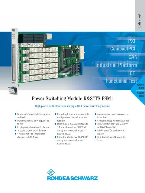
Data sheetVersion01.00<strong>Power</strong> <strong>Switching</strong> <strong>Module</strong> ¸<strong>TS</strong>-<strong>PSM1</strong>August2004High-power multiplexer and multiple DUT power switching module◆ <strong>Power</strong> switching module for suppliesand loads◆ <strong>Switching</strong> module for voltages of upto 70 V◆ 8 high-power channels with 16 A max.◆ 10 power channels with 2 A max.◆ 4 high-power 4-to-1 multiplexerchannels with 16 A max.◆ Indirect high-current measurementson high-power channels via shuntresistors◆ Direct current measurements up to1 A in all channels via ¸<strong>TS</strong>VPanalog measurement bus and¸<strong>TS</strong>-PSAM◆ Selftest of all relays via ¸<strong>TS</strong>VPanalog measurement bus and¸<strong>TS</strong>-PSAM◆ Analog measurement bus access to8 bus lines◆ Control interface based on CAN bus◆ Deployment in ¸Compact<strong>TS</strong>VPand ¸<strong>Power</strong><strong>TS</strong>VP◆ LabWindows/CVI device driversupport◆ G<strong>TS</strong>L test software library in DLLformat
Product introductionThe ¸<strong>TS</strong>-<strong>PSM1</strong> is a power switchingmodule controlled by a CAN-businterface. Its innovative technology andversatile functionality provide excellentsuitability for automotive and high-currentswitching applications, e.g. powermanagementand test-load paradigms.The special design of the moduleensures ideal routing of supply and loadpaths through the test system. High-currentforce channels and sense channelsfrom voltage or current sources can beswitched and routed to the DUTs via themodule. In the opposite direction, singlepoleor multipole loads can be appliedto the DUTs. High-power multiplexers onthe module provide selectability of differentload simulations that may be integratedin the ¸<strong>TS</strong>VP (Test SystemVersatile Platform) base units.The currents and voltages can be measuredor monitored at all switchingnodes by means of additional relays onthe module and the <strong>Rohde</strong> & <strong>Schwarz</strong>analog bus. Shunt resistors are integratedfor measuring high currents.This characteristic is particularly importantif the power consumption of theDUT must be measured during normaloperation and in standby modes. Additionally,the tests of various operatingmodes and their current consumptioncan be executed without interruptingthe DUT’s powerpath.The <strong>Power</strong> <strong>Switching</strong> <strong>Module</strong>¸<strong>TS</strong> <strong>PSM1</strong> can be used in the¸Compact<strong>TS</strong>VP and in the¸<strong>Power</strong><strong>TS</strong>VP. It is a CAN-buscontrolledmodule which takes up onlyone slot.Flexible signal routingThe design of the switching module andthe wide voltage and current rangesensure high flexibility and a wide applicationrange.Even complex yet flexible load systemswith original or electronic loads canbe configured to obtain a high- current¸<strong>Power</strong><strong>TS</strong>VP switching instrumentby means of device-internal connectionof the multiplexed power channels.When lower power signals are measured,the signal concept relies on the systemwideanalog bus.The appropriate way of handling analogsignals led to the interconnection solutionof the ¸<strong>TS</strong>VP analog bus. The analogbus is located immediately above thefront connector area where space is providedfor on-board signal conditioningand signal routing by coupling relays forthe analog bus. This distance to the digitalsignals on the backplane significantlyimproves signal quality.Additionally, the dedicated switchingmodules such as the ¸<strong>TS</strong>-<strong>PSM1</strong> arecontrolled via the low-noise and interference-resistantCAN bus, which ensuresoverall high reliability and signal quality,especially in the vicinity of high-currentsignals.2 <strong>Power</strong> <strong>Switching</strong> <strong>Module</strong> ¸<strong>TS</strong>-<strong>PSM1</strong>
Direct current measurement via the analogmeasurement bus is limited to 1 A, butmeasurements up to 16 A can be performedby forwarding the shunt resistorvoltages of the ¸<strong>TS</strong>-<strong>PSM1</strong> viathe analog bus to a precise multimetersuch as the ¸<strong>TS</strong>-PSAM in the¸Compact<strong>TS</strong>VP.Typical applications◆ <strong>Switching</strong> of voltage or currentsources to DUTs◆ <strong>Switching</strong> of DUT loads as originalloads or simulated/electronic loads◆ <strong>Power</strong> multiplexer for DUT signals totest devices◆ Analog functional test for generalpurposesignals◆ Switch simulation for DUTsSoft front panel for the ¸<strong>TS</strong>-<strong>PSM1</strong>Software supportSecurity by selftest anddiagnostic featuresA LabWindows/CVI driver accordingto the IVI standard is available for theswitching functions of the module.Function panels and online help areavailable as common features for theLabWindows/CVI driver.¸<strong>TS</strong>-<strong>PSM1</strong>The built-in selftest capability of themodule ranges from fast diagnosticsto the complete, automated evaluationof all relays and switching paths(¸<strong>TS</strong>-PSAM required). DiagnosticLEDs on the module front panel speed upsystem integration and allow proper operationto be determined at a glance.Certified Quality SystemISO 9001DQS REG. NO 1954 QMCertified Environmental SystemISO 14001DQS REG. NO 1954 UMAnalog bus (AB)IL1, IL2Analog busX30ABA1LABA1ABA2LABA2ABB1LABB1ABB2LABB2ABC1LABC1ABC2LABC2ABD1LABD1ABD2LABD2CouplingrelaisLocal analogbus (LAB)GNDFunctional block diagram of the ¸<strong>TS</strong>-<strong>PSM1</strong>Front connector X10IL1noIL1comIL2noIL2comCH9noCH9comCH10noCH10comCH11noCH11comCH12noCH12comCH13noCH13comCH14noCH14comCH15noCH15comCH16noCH16comIL1IL2A B C DCH1noCH2noCH3noCH4noCH5noCH6noCH7noCH8noBD0R010R010R010R01LABA1LABC1LABB2LABD20R010R010R010R01LABA2LABC2LPBALPBBCH1comTCH2comECH3comRM CH4comI CH5comN CH6comA CH7comLCH8comLPBDLPBCIL1comIL2comCH9comCH10comCH11comCH12comCH13comCH14comCH15comCH16comX1Extension connector X20GNDCHA-GNDGNDlines<strong>Power</strong> <strong>Switching</strong> <strong>Module</strong> ¸<strong>TS</strong>-<strong>PSM1</strong> 3
SpecificationsApplication in the ¸<strong>TS</strong>VP¸Compact<strong>TS</strong>VP1 slot required¸<strong>Power</strong><strong>TS</strong>VP1 slot requiredInterfaceControl busCAN 2.0b (1 Mbit/s)DUT connector (front)DIN 41612, 96 pinsRear I/O connectorCompactPCI connector J2, 110 pinsControl logicLocal microprocessorST10, 16 bit, 40 MHz<strong>Switching</strong> characteristicsHigh-power switching channelsNumber / type of relays8 / Zettler AZ764Contact configuration8 × SPST<strong>Switching</strong> voltage DC / AC max. 70 V DC, 46 V peak, 33 V rms<strong>Switching</strong> current max.16 A / 16 A rms (continuously)<strong>Switching</strong> power max.480 W / 4000 VA (resistive load)Current measurementIndirect via shunt 5 mΩ shunt resistor ±0.6 %±60 ppm/K (for 20 °C to 60 °C)Direct via analog buswith ¸<strong>TS</strong>-PSAM,1 A (10 W) max.High-power multiplexerNumber / type of relays16 / Zettler AZ764Contact configuration4 multiplexers 4-to-1<strong>Switching</strong> voltage DC / AC max. 70 V DC, 46 V peak, 33 V rms<strong>Switching</strong> current max.16 A / 16 A rms (continuously)<strong>Switching</strong> power max.480 W / 4000 VA (resistive load)Medium-power switching channelsNumber / type of relays10 / Zettler AZ832Contact configuration10 × SPST<strong>Switching</strong> voltage DC / AC max. 70 V DC, 46 V peak, 33 V rms<strong>Switching</strong> current max.2 A / 2 A rms (continuously)<strong>Switching</strong> power max.150 W / 250 VA (resistive load)Current measurementDirect via analog buswith ¸<strong>TS</strong>-PSAM,1 A (10 W) max.Monitor switching channelsNumber / type of relays6 / Meder RM-05Contact configuration12 multiplexers 4-to-1<strong>Switching</strong> voltage DC / AC max.<strong>Switching</strong> current max.<strong>Switching</strong> power max.Current measurementDirect via analog busAnalog measurement bus accessGeneral data70 V DC, 46 V peak, 33 V rms1 A / 1 A rms (1.5 A carry)10 Wwith ¸<strong>TS</strong>-PSAM,1 A (10 W) max.8 lines<strong>Power</strong> consumption+5 V / 4.0 A max.(all relays switched)EMC compliancecompliant with EMC directive89 / 336 / EEC and EMC standardEN 61326Safety CE, EN 61010 Part 1Mechanical loadingVibration test, sinusoidal5 Hz to 55 Hz: 2 g, MIL-T-28800D,class 5; 55 Hz to 150 Hz: 0.5 g,MIL-T-288800D, class 5Vibration test, random10 Hz to 300 Hz, 1.2 gShock test 40 g, MIL-STD-810, classes 3 and 5Temperature loadingOperating +5 °C to +40 °CPermissible 0 °C to +50 °CStorage –40 °C to +70 °CHumidity+40 °C, 95 % rel. humidityDimensions316 mm × 174 mm × 20 mmWeight0.75 kgCalibrationnot requiredOrdering informationDesignation Type Order No.<strong>Power</strong> <strong>Switching</strong> <strong>Module</strong> ¸<strong>TS</strong>-<strong>PSM1</strong> 1143.0139.02¸Compact<strong>TS</strong>VP Test andMeasurement Chassis ¸<strong>TS</strong>-PCA3 1152.2518.02¸<strong>Power</strong><strong>TS</strong>VP Industrial<strong>Switching</strong> Application Chassis ¸<strong>TS</strong>-PWA3 1157.8043.02More information atwww.rohde-schwarz.com(search term: <strong>TS</strong>-<strong>PSM1</strong>)www.rohde-schwarz.com¸is a registered trademark of <strong>Rohde</strong> & <strong>Schwarz</strong> GmbH & Co. KG · Trade names are trademarks of the owners · Printed in Germany (Pe bb)PD 0758.0616.32 · ¸<strong>TS</strong>-<strong>PSM1</strong> · Version 01.00 · August 2004 · Data without tolerance limits is not binding · Subject to change