Create successful ePaper yourself
Turn your PDF publications into a flip-book with our unique Google optimized e-Paper software.
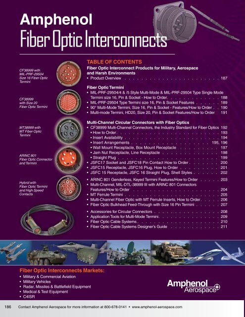
<strong>Fiber</strong> <strong>Optic</strong> <strong>Interconnects</strong>Product OverviewAmphenolAerospace38999IIIHDDualokIIISJTAccessoriesAquaconHerm/SealPCB<strong>Fiber</strong> <strong>Optic</strong>s in MIL-DTL-38999 Series III ConnectorsAmphenol Aerospace offers a wide range of fiber opticintercon nect solutions for use in the harsh environments found inmilitary and aerospace applications. Amphenol Aerospace hasestablished the rugged and reliable MIL-DTL-38999 as a com monconnector shell platform that houses a wide variety of fiber optictermini including MIL-PRF-29504 commercial equivalent*,HDF20, ARINC 801 and MT ferrules.*MIL-PRF-29504 supersedes MIL-T-29504. (MIL-T-29504 is stillavailable; consult Amphenol Aerospace for more information.)MIL-DTL-38999 Series III Tri-Start connectors areavailable in various insert arrangements, materials andfinishes to meet any type of environmental requirement.Our MIL-PRF-29504 style and HD20 termini can becombined with most of our copper contacts to create alarge assortment of hybrid fiber/copper connectorcombinations.Connector Termination FeaturesHighSpeed<strong>Fiber</strong><strong>Optic</strong>sContactsConnectorsCablesEMI FilterTransient26482Matrix 2MIL-PRF-29504CF38999 pin and socket termini that feature high precision, preradiusedceramic ferrules to help improve insertion loss performanceand reduce pol ishing time. Products are available in both single modeand multi-mode versions. The socket has a plastic protective shroudover the ceramic alignment sleeve thatincorporates a built-in anti-rotation fea ture.HD20 - Pin and socket termini that have the same benefits of theMIL-PRF-29504 termini, but in a smaller size 20 contact that allowsfor increased density in D38999 connector shells.83723 IIIMatrix|Pyle26500PyleJSFTight tolerance, nickel-plated composite plugs and receptaclesapproved for use in F35/JSF applications.5015Crimp RearReleaseMatrixARINC 801 terminiMT ferrulesGenderless fiber optic termini that use a precision 1.25 mm ceramicferrule. Preci sion inserts with guide pins and keyed termini enhancemulti-mode and single mode performance. ARINC 801 terminifacilitate an angled polish for improved return loss.Industry-standard, very high density plastic ferrules available in either12-fiber or 24-fiber versions, in multi-mode PC, single mode PC, andsingle mode APC configurations.Amphenol Aerospace also supplies a wide range of rectangular interconnect products containingMIL-PRF-29504 style, HD20 and MT <strong>Fiber</strong> <strong>Optic</strong> termini. Our rectangular interconnect products includea variety of applications including LRM surface mount and rack & panel styles - all available in hybridfiber/copper configurations22992Class LBack-ShellsOptionsOthersContact Amphenol Aerospace for more information at 800-678-0141 • www.amphenol-aerospace.com187
38999IIIHDDualokIIISJTAccessoriesAquaconHerm/SealPCBHighSpeed<strong>Fiber</strong><strong>Optic</strong>sContactsConnectorsCablesEMI FilterTransient26482Matrix 2AmphenolAerospaceOrdering Information for <strong>Fiber</strong> <strong>Optic</strong> PinsAmphenolPart Number<strong>Fiber</strong> Size†Core/CladdingMIL-PRF-29504/4 & /5 Style Multi-Mode,MIL-PRF-29504 Type Single Mode TerminiA Dia.Ref.(Microns)How to Order, Size 16, Pin and SocketFerruleHoleToleranceReference OnlyM29504/4-XXXXCF-198142-125 9/125 125 +1,–0 M201504/4-4300*CF-198142-25A 9/125 125.5 +1,–0 M29504/4-4208*CF-198142-126 9/125 126 +1,–0 M29504/4-4209*CF-198036-010CF-198142-01050/125 &62.5/12550/125 &62.5/125127 +2,–0CF-198036-017 100/140 145 +3,–0Superseded byMIL-PRF127 +2,–0 M29504/4-4040*Superseded byMIL-PRFCF-198142-017 100/140 145 +3,–0 M29504/4-4044*CF-198036-29A100/140/172Superseded by173 +1,–0(Polyimide)MIL-PRFCF-198142-29A100/140/172(Polyimide)173 +1,–0 M29504/4-4293*CF-198036-053 200/230 236 +4,–0Superseded byMIL-PRFCF-198142-053 200/230 236 +4,–0 M29504/4-4214*Ordering Information for <strong>Fiber</strong> <strong>Optic</strong> SocketsAmphenolPart Number<strong>Fiber</strong> Size†Core/CladdingA Dia.Ref.(Microns)FerruleHoleToleranceAlignmentSleeve**Reference OnlyM29504/5-XXXXCF-198143-125 9/125 125 +1,–0 C M29504/5-4309*Multi-mode Size 16 <strong>Fiber</strong><strong>Optic</strong> TerminiDesigned for use in the size 16contact cavities of Multi-channelMIL-DTL-38999 Series IIIConnectors and CF38999 <strong>Fiber</strong><strong>Optic</strong> Connectors83723 IIIMatrix|Pyle5015 26500Crimp Rear PyleReleaseMatrix22992Class LCF-198143-25A 9/125 125.5 +1,–0 C M29504/4-4237*CF-198143-126 9/125 126 +1,–0 C M29504/5-4238*CF-198035-010CF-198143-01050/125 &62.5/12550/125 &62.5/125127 +2,–0 MSuperseded byMIL-PRF127 +2,–0 C M29504/5-4046*CF-198035-017 100/140 145 +3,–0 MSuperseded byMIL-PRFCF-198143-017 100/140 145 +3,–0 C M29504/5-4050*CF-198035-29A 100/140/172(Polyimide)CF-198143-29A 100/140/172(Polyimide)173 +1,–0 MSuperseded byMIL-PRF173 +1,–0 C M29504/5-4296*CF-198035-053 200/230 236 +4,–0 MSuperseded byMIL-PRFCF-198143-053 200/230 236 +4,–0 C M29504/5-4243*Single Mode Size 16 <strong>Fiber</strong><strong>Optic</strong> TerminiDesigned for use in the size 16contact cavities of AmphenolCF38999 <strong>Fiber</strong> <strong>Optic</strong> ConnectorsBack-Shells* Consult Amphenol Aerospace forqualification status.† Additional fiber optic termini sizesavailable upon request; consult AmphenolAerospace for availability.** C = CeramicM = MetalOptionsOthers188Contact Amphenol Aerospace for more information at 800-678-0141 • www.amphenol-aerospace.com
MIL-PRF-29504 Type TerminiSize 16, Pin and Socket FeaturesAmphenolAerospaceAmphenol ® Multi-mode, Size 16 Termini Features:• Designed for use in size 16 cavities of MIL-DTL-38999 Series III and Amphenol CF38999 connectors• Precision ceramic ferrules which precisely position the fiber within the termini.• Available with metal or ceramic alignment sleeves• Stainless steel termini bodies and springs.• Allows for multiple fiber accommodationsAmphenol ® Single mode, Size 16 Termini Features:• Precision ceramic alignment sleeves ensure accurate fiber to fiber alignment.• Socket has threaded protective shroud with anti-rotation key, manu factured from rugged PEEK TM• Designed with similar high performance components as the size 16 multi-mode termini• Maintains fiber optic/electrical hybrid capabilities38999IIIHDDualokIIISJTAccessoriesAquaconHerm/SealPCBSize 16 Pin Termini.102 ±.001DIA.080 MAXCABLE DIAA DIAREF.0625 +.0000+.003DIA .297–.0002 –.002CERAMIC FERRULE1.093 ±.0201.176 MAX*Size 16 Socket Termini with Metal Alignment Sleeve1.500 MAX*STRENGTHMEMBER.162±.004SHRINK TUBE.06240 DIA+.00002–.00002.040 MAXBUFFERCABLE DIA.080 MAXCABLE DIAALIGNMENTSLEEVE**HighSpeed<strong>Fiber</strong><strong>Optic</strong>sContactsConnectorsCablesEMI FilterTransient26482Matrix 2.040 MAXBUFFERCABLE DIASHRINKTUBESTRENGTHMEMBER.102 ±.001DIACERAMICFERRULEA DIAREF.267±.00383723 IIIMatrix|PyleSize 16 Socket Termini with Ceramic Alignment Sleeve26500Pyle1.500 MAX*.080 MAXCABLE DIA..525 REF.1.093 ±.020.537 ±.008.128 +.002 DIA.–.0015015Crimp RearReleaseMatrix.040 MAXBUFFERCABLE DIA.SHRINKTUBETERMINUSSTRENGTHMEMBER.06248 ±.0002 DIA.CERAMIC FERRULEA DIA. REF.SHROUDALIGNMENTSLEEVE**22992Class L* Indicated dimension when fullyassembled.** Alignment sleeve shipped unassembled.All dimensions for reference only.Back-ShellsOptionsOthersContact Amphenol Aerospace for more information at 800-678-0141 • www.amphenol-aerospace.com189
AmphenolAerospace90° Multi-Mode TerminiSize 16, Pin and Socket38999IIIHDDualokIIISJTAccessoriesAquaconHerm/SealPCBHighSpeed<strong>Fiber</strong><strong>Optic</strong>sContactsConnectorsCables26482Matrix 283723 IIIMatrix|Pyle5015 26500Crimp Rear PyleReleaseMatrix22992Class LBack-ShellsOptionsOthersEMI FilterTransientAmphenol provides 90°, size 16 fiber optic termini that can be used with multi-channelcircular connectors. Consult Amphenol for the 90°, size 16 termini for use in LRMrectangular connectors. (Please consult Amphenol for availability of 90° size 20 termini).90° Socket Termini (Size 16)1.100SHRINK TUBING***.500 RADIUSREF.1.145 MAX..102 ±.001DIA.1.093 ±.020Ordering Information for 90° Multi-mode Socket Termini<strong>Fiber</strong> Size†Core/CladdingDia (Microns)1.820 MAX**+.002.128–.001DIA..537 REF..162±.004Socket, Size 16Amphenol Part NumberFor use in CircularConnectors.675 MAXCERAMICFERRULEA DIA.REF.InchesALIGNMENTSLEEVE***.267 +.003–.002A Dia RefMicrons50/12562.5/125CF-198111-010 .0050 127100/140 CF-198111-017 .0057 145CF-198111-29.0069 175100/140/172CF-198111-29A OR.0068173† Additional sizes available uponrequest: consult AmphenolAerospace for availability.* Consult Amphenol Aerospace forordering information.** Indicate dimension when fullyassembled.*** Shrink tubing and alignmentsleeve are shipped unassembled.For 90°, size 16 fiber optic termini foruse in LRM rectangular connectorsconsult Amphenol Aerospace.All dimensions for reference only.90° Pin Termini (Size 16)Ordering Information for 90° Multi-mode Pin Termini<strong>Fiber</strong> Size†Core/CladdingDia (Microns)Pin, Size 16Amphenol Part NumberFor use in CircularConnectorsInchesA Dia RefMicronsB Max(Inches)C Ref(Inches)50/12562.5/125CF-198110-010 .0050 127 1.121 1.100100/140 CF-198110-017 .0057 145 1.121 1.100100/140/172CF-198110-029 .0069 175 1.121 1.100ORCF-198110-29A .0068 173 1.121 1.10050/12562.5/125CF-198112-010 .0050 127 1.003 .900100/140 CF-198112-017 .0057 145 1.003 .900100/140/172CF-198112-029 .0069 175 1.003 .900ORCF-198112-29A .0068 173 1.003 .900SHRINKTUBING.500 RADIUS C REF.† Additional sizes available upon request: consult AmphenolAerospace for availability.* Consult Amphenol Aerospace for ordering information.For 90°, size 16 fiber optic termini for use in LRM rectangularconnectors consult Amphenol Aerospace.All dimensions for reference only..297 +.003–.002.102 ±.001DIA..128 +.002–.001 DIA.A DIA. REF.CERAMICFERRULEB MAX.190Contact Amphenol Aerospace for more information at 800-678-0141 • www.amphenol-aerospace.com
Multi-Mode Termini, HD20Size 20, Pin and Socket Features/How to OrderAmphenolAerospaceMulti-mode HDF20 <strong>Fiber</strong> <strong>Optic</strong> TerminiDesigned for use in the size 20 contact cavities ofMulti-channel MIL-DTL-38999 Series III Connectorsand Amphenol CF38999 <strong>Fiber</strong> <strong>Optic</strong> ConnectorsAmphenol ® Multi-mode, Size 20 Termini Features:• 1mm precision ceramic ferrules• Offers increased termini density• Designed with similar high performance components as size16 termini• Maintains fiber optic/electrical hybrid capabilities• Termination accomplished using epoxy/polish method.Ordering Information for Multi-modeTermini (Size 20) for MIL-DTL-38999 Connectors<strong>Fiber</strong> Size†Core/CladdingDia (Microns)Amphenol Part NumbersSize 20 SocketSize 20 PinA Dia. Ref.(Microns)Ferrule HoleTolerance50/12562.5/125CF-198080-010 CF-198081-010 127 +3,–0100/140 CF-198080-017 CF-198081-017 145 +3,–0† Additional sizes available upon request: consult Amphenol Aerospacefor availability.38999IIIHDDualokIIISJTAccessoriesAquaconHerm/SealPCBHighSpeed<strong>Fiber</strong><strong>Optic</strong>sContactsConnectorsCablesEMI FilterTransient26482Matrix 2Size 20 Multi-modePin Terminus.092 +.002 DIA.–.001A DIA.REF.1.176 MAX.*.833 ±.020.063 MAX.CABLE DIA.83723 IIIMatrix|Pyle+.00012.03937 –.00000DIA..297 +.003–.002CERAMIC FERRULESTRENGTHMEMBER.069 ±.001 DIA.SHRINK TUBE.037 MAX BUFFERCABLE DIA.26500PyleSize 20 Multi-modeSocket TerminusSTRENGTHMEMBER1.093 ±.0201.500 MAX.*.162 ±.002.03937 +.00012–.00000 DIA. ALIGNMENTSLEEVE**5015Crimp RearReleaseMatrix.063 MAX..037 MAX. BUFFER+.002CABLE DIA.CABLE DIA.SHRINK.092–.001DIA.TUBE.069 ±.001 DIA.CERAMICFERRULEA DIA.REF.263 ±.00422992Class LAmphenol ® Multi-Channel fiber optic connectors are supplied less termini. Order multimodetermini by Amphenol part number designation as shown in the chart above. ConsultAmphenol Aerospace for further availability.* Indicates dimension when fully assembled.** Alignment sleeve shipped unassembled.All dimensions for reference only.Back-ShellsOptionsOthersContact Amphenol Aerospace for more information at 800-678-0141 • www.amphenol-aerospace.com191
AmphenolAerospaceCF38999 Multi-Channel ConnectorsThe Industry Standard for <strong>Fiber</strong> <strong>Optic</strong>s38999IIIHDDualokIIISJTAccessoriesAquaconHerm/SealPCBHighSpeed<strong>Fiber</strong><strong>Optic</strong>sContactsConnectorsCablesEMI FilterTransient26482Matrix 283723 IIIMatrix|Pyle5015 26500Crimp Rear PyleReleaseMatrix22992Class LBack-ShellsOptionsOthers• Meets or exceeds MIL-DTL-38999 Series III requirements• EMI Shielding-solid metal-to-metal coupling, grounding fingers, electrolessnickel plating, and thicker wall sections provide superior EMI shieldingcapability of 65dB min. at 10 GHz.• Termini Protection-recessed pins in this 100% scoop-proof connectorminimize potential termini damage• Corrosion Resistance-shells of stainless steel or cadmium over nickel platingwithstand 500 hr. salt spray exposure• Vibration/Shock-operates under severe high temperature vibration• Threaded coupling quickly and completely mates in one 360° turn of thecoupling nutAdditional, composite connectors features include:• Lightweight - 17%-70% weight savings• Increased Corrosion Resistance-olive drab cadmium (175°C) and electrolessnickel plating (200°C) both withstand 2000 hours of salt spray exposure.• Durability-1500 couplings minimum (in reference to connector couplings,not termini)MECHANICAL/ENVIRONMENTALPARAMETERPERFORMANCEMaintenance Aging MIL-STD-1344 Method 2002Mating DurabilityInsert RetentionSine VibrationStandard ShockHigh Impact ShockTemperature LifeThermal ShockMATERIALS & FINISH CHARACTERISTICSSHELL MATERIAL/FINISHTEMPERATURERATING(DEG C)500 mating cycles100 PSI/25 lbs minimum60 G (140-2000 Hz), 4 hours each atambient, -55 deg C, and +175 deg C300 G half-sine, 3 ms durationMIL-S-901 grade A with lightweightfixture1000 hours @ high temp rating-55° C to +165° C - 5 cyclesSALT SPRAYRATING(HOURS)MIL-DTL-38999SERVICE CLASSAluminum/Durmalon -65 to +175 500 TAluminum/electroless nickel -65 to +200 500 FAluminum/olive drab cadmiumplate nickel base-65 to +175 500 WStainless steel -65 to +200 500 KComposite/electroless nickel -65 to +200 2000 MComposite/ olive drab cadmiumplate nickel base-65 to +175 2000 JThe illustration above shows the keyfeatures of the CF38999. The highestoptical performance connectorconforming to MIL-DTL-389991. Beryllium-copper retention clip forimproved termini stability2. Precision-aligned inserts3. Modified master key4. Integrated wave washer forimproved performance in highvibration environments192Contact Amphenol Aerospace for more information at 800-678-0141 • www.amphenol-aerospace.com
AmphenolAerospaceMulti-Channel <strong>Fiber</strong> <strong>Optic</strong> CircularInsert Availability, (CF38999 Connector)38999IIIHDDualokIIISJTAccessoriesAquaconHerm/SealPCBHighSpeed<strong>Fiber</strong><strong>Optic</strong>sContactsConnectorsCablesEMI FilterTransient26482Matrix 283723 IIIMatrix|Pyle5015 26500Crimp Rear PyleReleaseMatrix22992Class LBack-Shells<strong>Fiber</strong> optic termini can be accommodated in any size 16 or size 20 contact cavity ofMIL-DTL-38999 Series III type connector insert patterns, as listed in the following chart.For availability of fiber type, either multi-mode or single mode, see note at bottom of chart.Shell Size/ArrangementTotalContactsContact Size<strong>Optic</strong> Termini12Availability* 12(Coax)10(Power)OptionsOthers8(Coax)8(Twinax)F22D20 1609-94 2 209-98 3 311-02 2 211-05 5 511-98 6 611-99 7 713-04 4 413-08 8 813-13 4 2** 213-98 10 1015-05 5 515-15 15 14 115-18 18 1815-19 19 1915-97 12 8 417-08 8 817-26 26 2617-99 23 21 219-11 11 1119-28 28 26 219-32 32 3221-16 16 1621-29 27 19 4 421-39 39 37 221-41 41 4123-21 21 2123-53 53 5323-54 53 40 9 423-55 55 5525-04 56 48 825-11*** 11 2 925-20*** 30 10 13 4 325-24 24 12 1225-26 25 16 5 425-29 29 2925-37 37 3725-41 41 22 3 11 2 325-43 43 23 2025-46 46 40 4 2†25-61 61 6125-90 46 40 4 225-F4 66 49 13 4* Size 16 multi-mode and single mode fiber optic termini are readily available.For size 20 multi-mode termini consult Amphenol Aerospace for availability.** Two size 16 contacts dedicated to fiber optics.*** For use in MIL-STD-1760 applications. See 38999 Series III section in this catalog.† For RG180/U and RG195/U cables only. Contact Amphenol for other cableapplications.F Size 8 coax and Twinax are interchangeable.For service ratings and performance of electrical contacts see 38999 Series III section in this catalog.194Contact Amphenol Aerospace for more information at 800-678-0141 • www.amphenol-aerospace.com
Multi-Channel <strong>Fiber</strong> <strong>Optic</strong> Circular(CF38999 Connector) Insert ArrangementsAmphenolAerospaceFront face of pin inserts illustratedBB ACDACABAH BG CK JF DEEDBAAInsert Arrangement 09-94 09-98 11-02 11-05 11-98 11-99 13-04 13-08Number of Contacts 2 3 2 5 6 7 4 8Contact Size 20 20 16 20 20 20 16 20CBDECABKL AMBJHR NPCDG EFEDAFCBL AK M N BT U PJCS RHDGF EEDFGCABM ABL N PCK U V RJ T SDHEG FDABCHJGGFFEABHCDKAL BCInsert Arrangement 13-13 13-98 15-05 15-15 15-18 15-19 15-97Number of Contacts 2 2 10 5 14 1 18 19 8 4Contact Size 16 12 20 16 20 16 20 20 20 16Dedicated to<strong>Fiber</strong> <strong>Optic</strong>sMED38999IIIHDDualokIIISJTAccessoriesAquaconHerm/SealPCBHighSpeed<strong>Fiber</strong><strong>Optic</strong>sContactsConnectorsCablesEMI FilterTransientFGEHADBCAR BP S T CaUbNDZc VMEY WL XGFKJ HR AP S TYN ZXM WLKJHGBU CVFDEHGFJKLEADBCT AS U BRdVCPNcbeZWXDEMa Y FL J GK HInsert Arrangement 17-08 17-26 17-99 19-11 19-28Number of Contacts 2 26 21 2 11 26 2Contact Size 16 20 20 16 16 20 1626482Matrix 283723 IIIMatrix|Pyle26500PyleABTS UR e V CPNdcjbfghWXDEMYaFZL J GK HJHKGSLRMFPANEBDCAU V WBTCjXYS iDk Zh rm a ER g q n bPfc FNdepGMHL JKAV W BUCjXY DT i ksZm EShtran FRg q p bc GPfe dNHMJL KInsert Arrangement 19-32 21-16 21-39 21-41Number of Contacts 32 16 37 2 41Contact Size 20 16 20 16 205015Crimp RearReleaseMatrix22992Class LBack-ShellsOptionsOthersCONTACT LEGEND 8 10 12 16 20 22DContact Amphenol Aerospace for more information at 800-678-0141 • www.amphenol-aerospace.com195
AmphenolAerospaceMulti-Channel <strong>Fiber</strong> <strong>Optic</strong> Circular(CF38999 Connector) Insert Arrangements38999IIIHDDualokIIISJTAccessoriesAquaconHerm/SealPCBHighSpeed<strong>Fiber</strong><strong>Optic</strong>sContactsConnectorsCablesFront face of pin inserts illustratedLKJMVHWNUGPXTARFSBECDAR S T Bn UP m p VCkWN AABBqDzrM h GG CC X Ey HH sL g FF DD YxFEE tf w uaZK e vd bJ c GHAT U V BW CSXm n p YAA q DkR z GG BB r Zj y HH CCEFFaPsi EE DDxFt bN h w ucg vd GfMeHLK JInsert Arrangement 23-21 23-53 23-55Number of Contacts 21 53 55Contact Size 16 20 20EMI FilterTransient26482Matrix 283723 IIIMatrix|PyleAZBa CY wvbc DX u GGxEFFdW tHH ye FVs EE LL JJ z fr DD KK AAUg Gq CC BBhTHpkSnm JR N KP LMNMInsert Arrangement 25-04 25-29 25-37Number of Contacts 48 6 29 37Contact Size 20 16 16 16PLaRKbZSYJfAceTXHdUBWGVFCEDRPSNTedMcUfqbLgphrAnKVkJaBWmZHXYCDGEF5015 26500Crimp Rear PyleReleaseMatrix22992Class LABX Y Z CWpna DVEmbUw qFkcv x rT hd Gu t sSHgeR fJPKNMLZ ABY avbX ucCt GGWHH w d DsFFxNN JJEVeEE PPU r MM KK yf FLLqz g GTDDp BB AA h HCCS ni JR m k jPMKN LBack-ShellsOptionsOthersInsert Arrangement 25-43 25-61Number of Contacts 23 20 61Contact Size 20 16 20*** For use in MIL-STD-1760 applications. See 38999 Series III section in this catalog.† 12 Coax Contacts can be Matched Impedance or PowerCONTACT LEGEND 8 10 12 16 20 22D196Contact Amphenol Aerospace for more information at 800-678-0141 • www.amphenol-aerospace.com
Multi-Channel <strong>Fiber</strong> <strong>Optic</strong> Circular(CF38999) Wall Mount/Box Mount ReceptaclesAmphenolAerospaceWall Mount Receptacle with<strong>Fiber</strong> <strong>Optic</strong>s shell style 0For complete part number,see how to order, page 193.† Red Band indicates fully mated†† Blue band indicates rear release contactretention systemShellSizeDesignates true position dimensioningAll dimensions for reference onlyMSShellSizeCodeB ThreadClass 2A0.1P-0.3L-TS(Plated)LMax.(TV)L 1Max.(CTV)M+.000–.005(TV)TRI-START TM METAL AND COMPOSITE CONNECTORSM 1+.000–.005(CTV)S2 PLACESR 12 PLACESR 22 PLACESTT4 PLACESR 1 R 2 SMax..005 MT+.008B THREADT4 PLACESVThreadMetricZMax.(TV)LL (TV)LL 1 (CTV)M (TV)M 1(CTV)AAREDBAND †BLUEBAND ††Z 1Max.(CTV)Z (TV)Z 1(CTV)1.240 MAXL (TV)L 1 (CTV)–A–A 1 Dia.BackPanelMountA 2 Dia.FrontPanelMountVTHREADAAMax.PanelThicknessA 1BACK PANELMOUNTINGA 2FRONT PANELMOUNTING9 A .6250 .469 .514 .820 .773 .719 .594 .948 .128 M12X1-6g .153 .198 .650 .510 .234 .905 .908 .21611 B .7500 .469 .514 .820 .773 .812 .719 1.043 .128 M15X1-6g .153 .198 .800 .620 .234 .905 .908 .19413 C .8750 .469 .514 .820 .773 .906 .812 1.137 .128 M18X1-6g .153 .198 .910 .740 .234 .905 .908 .19415 D 1.0000 .469 .514 .820 .773 .969 .906 1.232 .128 M22X1-6g .153 .198 1.040 .900 .234 .905 .908 .17317 E 1.1875 .469 .514 .820 .773 1.062 .969 1.323 .128 M25X1-6g .153 .198 1.210 1.010 .234 .905 .908 .19419 F 1.2500 .469 .514 .820 .773 1.156 1.062 1.449 .128 M28X1-6g .153 .198 1.280 1.130 .234 .905 .908 .19421 G 1.3750 .500 .545 .790 .741 1.250 1.156 1.575 .128 M31X1-6g .183 .228 1.410 1.250 .204 .905 .904 .19423 H 1.5000 .500 .545 .790 .741 1.375 1.250 1.701 .154 M34X1-6g .183 .228 1.530 1.360 .204 .905 .904 .24225 J 1.6250 .500 .545 .790 .741 1.500 1.375 1.823 .154 M37X1-6g .183 .228 1.660 1.470 .204 .905 .904 .242LL+.006–.000(TV)LL 1±.005(CTV)TT±.00838999IIIHDDualokIIISJTAccessoriesAquaconHerm/SealPCBHighSpeed<strong>Fiber</strong><strong>Optic</strong>sContactsConnectorsCablesEMI FilterTransient26482Matrix 2Box Mount Receptacle with <strong>Fiber</strong><strong>Optic</strong>s shell style 2For complete part number,see how to order, page 193.Consult Amphenol Aerospace for availability ofcomposite box mount receptacles.S2 PLACESR 12 PLACESR 22 PLACESBLUEBAND††REDBAND †Z (TV)Z 1(CTV)L (TV)L 1(CTV)A 1BACK PANELMOUNTING83723 IIIMatrix|Pyle26500Pyle† Red Band indicates fully mated†† Blue band indicates rear release contactretention systemShellSizeDesignates true position dimensioningAll dimensions for reference onlyMSShellSizeCodeB ThreadClass 2A0.1P-0.3L-TS(Plated)LMax.(TV)L 1Max.(CTV)M+.000–.005(TV)M 1+.000–.005(CTV)TT4 PLACES.005 MR 1 R 2 SMaxT+.008T4 PLACESZMax.(TV)BTHREADZ 1Max.(CTV)A 1 Dia.BackPanelMountAAM (TV)M 1(CTV)LL (TV)LL 1 (CTV)A 2 Dia.FrontPanelMountAAMax.PanelThickness9 A .6250 .205 .250 .820 .773 .719 .594 .948 .128 .153 .198 .650 .510 .234 .905 .908 .21611 B .7500 .205 .250 .820 .773 .812 .719 1.043 .128 .153 .198 .800 .620 .234 .905 .908 .19413 C .8750 .205 .250 .820 .773 .906 .812 1.137 .128 .153 .198 .910 .740 .234 .905 .908 .19415 D 1.0000 .205 .250 .820 .773 .969 .906 1.232 .128 .153 .198 1.040 .900 .234 .905 .908 .17317 E 1.1875 .205 .250 .820 .773 1.062 .969 1.323 .128 .153 .198 1.210 1.010 .234 .905 .908 .19419 F 1.2500 .205 .250 .820 .773 1.156 1.062 1.449 .128 .153 .198 1.280 1.130 .234 .905 .908 .19421 G 1.3750 .235 .280 .790 .741 1.250 1.156 1.575 .128 .183 .228 1.410 1.250 .204 .905 .904 .19423 H 1.5000 .235 .280 .790 .741 1.375 1.250 1.701 .154 .183 .228 1.530 1.360 .204 .905 .904 .24225 J 1.6250 .235 .280 .790 .741 1.500 1.375 1.823 .154 .183 .228 1.660 1.470 .204 .905 .904 .242LL+.006–.000(TV)A 2FRONT PANELMOUNTINGLL 1±.005(CTV)TT±.0085015Crimp RearReleaseMatrix22992Class LBack-ShellsOptionsOthersContact Amphenol Aerospace for more information at 800-678-0141 • www.amphenol-aerospace.com197
AmphenolAerospaceMulti-Channel <strong>Fiber</strong> <strong>Optic</strong> Circular(CF38999) Jam Nut/Line Receptacles38999IIIHDDualokIIISJTAccessoriesAquaconHerm/SealPCBHighSpeed<strong>Fiber</strong><strong>Optic</strong>sContactsConnectorsCablesEMI FilterTransientJam Nut Receptacle with <strong>Fiber</strong><strong>Optic</strong>s shell style 7For complete part number,see how to order, page 193.† Red Band indicates fully mated†† Blue band indicates rear release contactretention systemH .059 dia. min. 3 lockwire holesFormed lockwire hole design (6 holes) is optionalAll dimensions for reference onlyShellSizeMS ShellSize CodeA •+.000–.010B ThreadClass 2A0.1P-0.3L-TS (Plated)TRI-START TM METAL AND COMPOSITE CONNECTORSCMax.D 1+.010–.000D 2+.000–.010H Hex+.017–.016S±.010T+.010–.000VThreadMetric9 A .669 .6250 1.199 .700 .670 .875 1.062 .697 M12X1-6g11 B .769 .7500 1.386 .825 .770 1.000 1.250 .822 M15X1-6g13 C .955 .8750 1.511 1.010 .955 1.188 1.375 1.007 M18X1-6g15 D 1.084 1.0000 1.636 1.135 1.085 1.312 1.500 1.134 M22X1-6g17 E 1.208 1.1875 1.761 1.260 1.210 1.438 1.625 1.259 M25X1-6g19 F 1.333 1.2500 1.949 1.385 1.335 1.562 1.812 1.384 M28X1-6g21 G 1.459 1.3750 2.073 1.510 1.460 1.688 1.938 1.507 M31X1-6g23 H 1.575 1.5000 2.199 1.635 1.585 1.812 2.062 1.634 M34X1-6g25 J 1.709 1.6250 2.323 1.760 1.710 2.000 2.188 1.759 M37X1-6gCTHS2 PLACESAB THREADPANEL THICKNESS.062 MIN..125 MAX.REDBAND †.091 MAX.–A–K REF..871 (SHELL SIZES 9/11).878 (SHELL SIZES 13/25)1.280 MAX.BLUE BAND ††.378 MAX.V THREADD 1 D 2JAM NUTD-HOLEMOUNTING26482Matrix 283723 IIIMatrix|PyleLine Receptacle with <strong>Fiber</strong> <strong>Optic</strong>sshell style 1For complete part number,see how to order, page 193.GG (TV)GG 1(CTV)BTHREADLL (TV)LL 1 (CTV)M (TV)M 1(CTV).280 MIN. FULL THDV THREAD5015 26500Crimp Rear PyleReleaseMatrix22992Class LBack-ShellsOptionsOthers† Red Band indicates fully mated†† Blue band indicates rear release contactretention systemAll dimensions for reference onlyShellSizeMS ShellSize CodeB Thread0.1P-0.3L-TS-2A(Plated)LMax.(TV)L 1Max.(CTV)M+.000–.005(TV)M 1+.000–.005(CTV)S±.010(TV)S (TV)S 1(CTV)2 PLACESS 1±.010(CTV)VThreadMetric9 A .6250 .469 .514 .820 .773 .675 .635 M12X1-6g .153 .198 .812 .699 .905 .90811 B .7500 .469 .514 .820 .773 .800 .765 M15X1-6g .153 .198 .905 .875 .905 .90813 C .8750 .469 .514 .820 .773 .925 .885 M18X1-6g .153 .198 1.093 1.007 .905 .90815 D 1.0000 .469 .514 .820 .773 1.050 1.100 M22X1-6g .153 .198 1.219 1.140 .905 .90817 E 1.1875 .469 .514 .820 .773 1.238 1.197 M25X1-6g .153 .198 1.375 1.229 .905 .90819 F 1.2500 .469 .514 .820 .773 1.300 1.260 M28X1-6g .153 .198 1.469 1.380 .905 .90821 G 1.3750 .500 .545 .790 .741 1.425 1.385 M31X1-6g .183 .228 1.625 1.493 .905 .90423 H 1.5000 .500 .545 .790 .741 1.550 1.510 M34X1-6g .183 .228 1.750 1.626 .905 .90425 J 1.6250 .500 .545 .790 .741 1.675 1.635 M37X1-6g .183 .228 1.875 1.777 .905 .904ZMax.(TV)REDBAND †BLUEBAND ††Z 1Max.(CTV)Z (TV)Z 1(CTV)1.240 MAX.GGDia.±.010(TV)–A–GG 1Dia.±.010(CTV)L (TV)L 1 (CTV)LL+.006–.000(TV)LL 1±.005(CTV)198Contact Amphenol Aerospace for more information at 800-678-0141 • www.amphenol-aerospace.com
Multi-Channel <strong>Fiber</strong> <strong>Optic</strong> Circular(CF38999) Straight PlugAmphenolAerospaceStraight Plug with <strong>Fiber</strong> <strong>Optic</strong>sshell style 6For complete part number,see how to order, page 193.TRI-START TM METAL AND COMPOSITE CONNECTORSMETALVTHREAD.359 MAX.1.234 MAX.1.220 MAX..591 +.003–.000–A–B THREADBLUE BAND †Q38999IIIHDDualokIIISJTAccessoriesAquaconHerm/SealPCBCOMPOSITE1.234 MAX.B THREADQHighSpeed<strong>Fiber</strong><strong>Optic</strong>sContactsConnectorsCables† Blue band indicates rear release contactretention systemVTHREAD.359 MAX..591 +.003–.000 –A–BLUE BAND †EMI FilterTransientShellSizeMS ShellSize CodeB Thread0.1P-0.3L-TS-2B(Plated)Q Dia.Max.V ThreadMetric9 A .6250 .858 M12X1-6g11 B .7500 .984 M15X1-6g13 C .8750 1.157 M18X1-6g15 D 1.0000 1.280 M22X1-6g17 E 1.1875 1.406 M25X1-6g19 F 1.2500 1.516 M28X1-6g21 G 1.3750 1.642 M31X1-6g23 H 1.5000 1.768 M34X1-6g25 J 1.6250 1.890 M37X1-6g26482Matrix 283723 IIIMatrix|Pyle26500Pyle5015Crimp RearReleaseMatrix22992Class LBack-ShellsOptionsOthersContact Amphenol Aerospace for more information at 800-678-0141 • www.amphenol-aerospace.com199
38999IIIHDDualokIIISJTAccessoriesAquaconHerm/SealPCBHighSpeed<strong>Fiber</strong><strong>Optic</strong>sContactsConnectorsCablesEMI FilterTransientAmphenolAerospace• Approved for use in JSF/F35 applications• Precision ceramic ferrules which precisely position thefiber within the termini• Precision ceramic alignment sleevesensure accurate fiber-to-fiber alignment• Socket has threaded protective shroud with anti-rotationkey, manufactured from rugged PEEK TM material,provides protection for the ceramic alignment sleeve• Stainless steel termini bodies and springsJSFC17 Socket and JSFC18 Pin ContactHow to OrderOrder Information for<strong>Fiber</strong> <strong>Optic</strong> PinAmphenol PartNo.<strong>Fiber</strong> SizeCore/CladdingA Dia.Ref.(Microns)Ferrule HoleToleranceJSFC18-1 CF-198142-25A 9/125 125.5 +1,-0JSFC18-2 CF-198142-126 50/125 126 +1,-0JSFC18-3 CF-198142-053 200/230 236 +4,-0Ordering Information for<strong>Fiber</strong> <strong>Optic</strong> SocketAmphenol Part No.<strong>Fiber</strong> SizeCore/CladdingA Dia.Ref.(Microns)FerruleHoleToleranceJSFC17-1 CF-198143-25A 9/125 125.5 +1,-0JSFC17-2 CF-198143-126 50/125 126 +1,-0JSFC17-3 CF-198143-053 200/230 236 +4,-026482Matrix 2CF-198142-XXXJSFC18-XA DIA.REF..853 MAX.CERAMIC FERRULE.080 MAX.CABLE DIA.83723 IIIMatrix|PyleSize 16 Pin Terminus.06248 ±.00002 DIA..266±.004.297 +.003–.002SHRINK TUBE.50± .10.069 MAX.5015 26500Crimp Rear PyleReleaseMatrixCF-198143-XXXJSFC17-XSize 16 Socket Terminus.107 +.003–.015.06248.117 MAXA DIA. REF..537SPRINGFERRULEALIGNMENT SLEEVEPROTECTIVE COVER1.223 MAX(1.025).50 ±.10SHRINK TUBE.069.080 MAXCABLE22992Class LBack-ShellsOptionsOthersMECHANICAL/ENVIRONMENTALPARAMETERPERFORMANCECable pull-out force22 lbs for 1 minuteMating durability500 cyclesShock - high impactMIL-S-901 Grade A, Type B, Class IShock - half sine pulse300 g, 3 ms durationVibration - sine60 g, 36 cyclesVibration - random49.5 g rmsVibration - random at temperature 41.7 g rms @125 deg CSalt spray48 hours direct exposure @ 35 deg CThermal shock-55 deg C to +165 deg C, 5 cyclesTemperature Life165 deg C for 1000 hoursMATERIALS LISTCOMPONENTMATERIALFerruleZirconiaAlignment sleeveZirconiaTermini body Stainless Steel – AMS 5514Spring Stainless Steel – AMS 5678Alignment sleeve shroud PEEKHeat shrinkKynar, MIL-I-23053/8200Contact Amphenol Aerospace for more information at 800-678-0141 • www.amphenol-aerospace.com
JSFC15 Receptacle /JSF16 Plug ConnectorsHow to OrderAmphenolAerospace• Approved for use in JSF/F35 applications• Based on Amphenol ® Composite Tri-Start, Qualified toMIL-DTL-38999, Rev. J.• Increased Corrosion Resistance-nickel plating (200°C) bothwithstand 2000 hours of salt spray exposure.• Durability-1500 couplings minimum(in reference to connector couplings, not termini)• Termini Protection-recessed pins in this 100% scoop-proofconnector minimize potential termini damage• Vibration/Shock-operates under severe high temperature vibration• Threaded coupling quickly and completely mates in one 360° turnof the coupling nutMECHANICAL/ENVIRONMENTALPARAMETERPERFORMANCEMaintenance Aging MIL-STD-1344 Method 2002Mating DurabilityInsert RetentionSine VibrationStandard ShockHigh Impact ShockTemperature LifeThermal Shock500 mating cycles100 PSI/25 lbs minimum60 G (140-2000 Hz), 4 hours each at ambient,-55 deg C, and +175 deg C300 G half-sine, 3 ms durationMIL-S-901 grade A with lightweight fixture1000 hours @ high temp rating-55° C to +165° C - 5 cyclesEasy Steps to build a part number... JSFC15 & JSFC161. 2. 3. 4. 5. 6.Program PartNumberShellStylesServiceClassShell Size –Insert arrangementContact TypeAlternatePositionsJSFC15 20 M E – 8 A NJSFC16 26 M E – 8 B NJSFC15 Receptacle andJSFC16 <strong>Fiber</strong> <strong>Optic</strong> Plug38999IIIHDDualokIIISJTAccessoriesAquaconHerm/SealPCBHighSpeed<strong>Fiber</strong><strong>Optic</strong>sContactsConnectorsCablesEMI FilterTransient26482Matrix 283723 IIIMatrix|Pyle26500PyleJSFC15JSFC16DesignatesReceptacle circular fiber opticPlug circular fiber opticDesignates20 JSFC15 Wall Mount Receptacle26 JSFC16 Straight PlugMStep 1. Select a Connector TypeStep 2. Select a Shell StyleStep 3. Select a Service ClassDesignatesComposite, electroless nickel plateStep 4. Select a Shell Size – Insert ArrangementShell Sizes are MIL-DTL-38999, Series III,plus newer High Density Insert ArrangementsShell Size InsertArrangementB – (11) 2C – (13) 4D – (15) 5E – (17) 8Step 5. Select a Contact TypeABDesignatesPin contactsSocket contactsStep 6. Select an Alternate PositionA, B, C, D, E, N for normalShell Size InsertArrangementF – (19) 11G – (21) 16H – (23) 21J – (25) 29J – (25) 375015Crimp RearReleaseMatrix22992Class LBack-ShellsOptionsOthersContact Amphenol Aerospace for more information at 800-678-0141 • www.amphenol-aerospace.com201
AmphenolAerospaceJSFC15 Wall Mount ReceptacleJSFC16 Straight Plug38999IIIHDDualokIIISJTAccessoriesAquaconHerm/SealPCBHighSpeed<strong>Fiber</strong><strong>Optic</strong>sContactsConnectorsCablesEMI FilterTransient26482Matrix 2JSFC15Wall Mount Receptacle with<strong>Fiber</strong> <strong>Optic</strong>sShell Style 20For complete part number see how toorder, page 201† Red Band indicates fully mated†† Blue band indicates rear release contactretention systemShellSizeDesignates true position dimensioningAll dimensions for reference onlyMSShellSizeCodeB ThreadClass 2A0.1P-0.3L-TS(Plated)LMax.(TV)L 1Max.(CTV)M+.000–.005(TV)M 1+.000–.005(CTV)GGGG 1(Composite)SS 1 (Composite)2 PLACESR 1 R 2 SMax.BTHREADT+.008METALLLLL 1 (Composite)MM 1(Composite)REDBAND †ZZ 1BLUEBAND †† (Composite)–A–VThreadMetric1.240 MAX.1.234 MAX.1.220 MAX.Z Z 1Max. Max.(TV) (CTV)A 1 Dia.BackPanelMount.280 MIN. FULL THDV THREADLL 1 (Composite)A 2 Dia.B THREAD FrontPanelMountAAMax.PanelThicknessLL+.006–.000(TV)A 1BACK PANELMOUNTINGA 2FRONT PANELMOUNTING9 A .6250 .469 .514 .820 .773 .719 .594 .948 .128 M12X1-6g .153 .198 .650 .510 .234 .905 .908 .21611 B .7500 .469 .514 .820 .773 .812 .719 1.043 .128 M15X1-6g .153 .198 .800 .620 .234 .905 .908 .19413 C .8750 .469 .514 .820 .773 .906 .812 1.137 .128 M18X1-6g .153 .198 .910 .740 .234 .905 .908 .19415 D 1.0000 .469 .514 .820 .773 .969 .906 1.232 .128 M22X1-6g .153 .198 1.040 .900 .234 .905 .908 .17317 E 1.1875 .469 .514 .820 .773 1.062 .969 1.323 .128 M25X1-6g .153 .198 1.210 1.010 .234 .905 .908 .194V19 F 1.2500 .469 .514 .820 .773 1.156 1.062 1.449 .128 THREAD M28X1-6g .153 .198 1.280 1.130 .234 .905 .908 .194BLUE BAND †21 G 1.3750 .500 .545 .790 .741 1.250 1.156 1.575 .128 M31X1-6g .183 .228 1.410 1.250 .204 .905 .904 .194.359 MAX..591 +.00323 H 1.5000 .500 .545 .790 .741 1.375 1.250 1.701 .154 M34X1-6g .183 .228–.0001.530 1.360 .204 .905 .904 .242–A–25 J 1.6250 .500 .545 .790 .741 1.500 1.375 1.823 .154 M37X1-6g .183 .228 1.660 1.470 .204 .905 .904 .242LL 1±.005(CTV)TT Q±.00883723 IIIMatrix|Pyle5015 26500Crimp Rear PyleReleaseMatrix22992Class LBack-ShellsOptionsOthersJSFC16Straight Plug with <strong>Fiber</strong> <strong>Optic</strong>sShell Style 26For complete part number seehow to order, page 201† Blue band indicates rear release contactretention systemAll dimensions for reference onlyShellSizeMS ShellSize CodeB Thread0.1P-0.3L-TS-2B(Plated)Q Dia.Max.V ThreadMetric9 A .6250 .858 M12X1-6g11 B .7500 .984 M15X1-6g13 C .8750 1.157 M18X1-6g15 D 1.0000 1.280 M22X1-6g17 E 1.1875 1.406 M25X1-6g19 F 1.2500 1.516 M28X1-6g21 G 1.3750 1.642 M31X1-6g23 H 1.5000 1.768 M34X1-6g25 J 1.6250 1.890 M37X1-6gCOMPOSITEVTHREAD.359 MAX.1.234 MAX..591 +.003–.000 –A–B THREADBLUE BAND †Q202Contact Amphenol Aerospace for more information at 800-678-0141 • www.amphenol-aerospace.com
ARINC 801 TerminiGenderless, Keyed Termini Features/How to OrderAmphenolAerospaceARINC 801 TerminiDesigned for use in ARINC 801 <strong>Fiber</strong> <strong>Optic</strong> ConnectorsARINC 801TerminiA DIA.REF..194±.001Ordering Information forARINC 801 Termini for ARINC 801ConnectorsAmphenol ARINC 801 TerminiPart Number.570 ±.010.320 MAX..297 ±.020A Dia. RefFerruleHoleToleranceCF-198148-126 126 +1, -0CF-198148-128 128 +2, -0Amphenol ® ARINC 801 Termini Features:• Designed for use in Amphenol ARINC 801 fiber opticconnectors - manufactured to comply with ARINC 801.• Genderless terminus allows for use on both sides ofa connector• Alignment sleeves are contained in a separate carrier whichis removable for easier end-face cleaning• Precision ceramic ferrules and sleeves ensure accuratefiber-to-fiber alignment• Keyed to provide anti-rotation• Available with both PC and APC end-face finishes• Terminus body is crimped to the cable providing a“Pull-Proof” advantageAmphenol ARINC fiber optic connectors are supplied lesscontacts. Order ARINC 801 termini by Amphenol part numberdesignation as shown in the chart at right. Consult Amphenol,Sidney, NY for further availability.See page 204 for information on ARINC 801 termini in circular38999 connectors.38999IIIHDDualokIIISJTAccessoriesAquaconHerm/SealPCBHighSpeed<strong>Fiber</strong><strong>Optic</strong>sContactsConnectorsCablesEMI FilterTransient26482Matrix 283723 IIIMatrix|PyleFERRULEREAR BODYCRIMP SLEEVE26500PyleOPTICAL / MECHANICAL / ENVIRONMENTALParameterInsertion Loss (850 nm)Return Loss (850 nm)Thermal CyclingAltitude ImmersionTemperature LifeVibrationMechanical ShockHumiditySalt SprayFluid ImmersionPerformance0.30 dB max., 0.15 dB typical (multi-mode)–20 dB max., – 40 dB typical (multi-mode)EIA 364-032D, Test condition VII(–55C to +100C; 5 cycles)TIA/EIA-455-15TIA/EIA-455-4 (100C for 1000 hours)TIA/EIA-455-11 (condition VI-G, eight hrs. per axis)TIA/EIA-455-14, Condition DTIA/EIA-455-5EIA-364-026B, Condition C (500 hours)Standard Aerospace FluidsAll dimensions for reference only.TERMINI COMPONENTS / MATERIALSComponentOuter bodySpringFerruleStainless SteelMaterialStainless Steel, passivatedZirconia CeramicORDERING INFORMATIONARINC 801 TERMINIAmphenol ARINC 801Termini Part NumberA Dia.Ref.Ferrule HoleToleranceCF-198148-126 126 +1, –0CF-198148-128 128 +2, –05015Crimp RearReleaseMatrix22992Class LBack-ShellsOptionsOthersContact Amphenol Aerospace for more information at 800-678-0141 • www.amphenol-aerospace.com203
AmphenolAerospaceMulti-Channel <strong>Fiber</strong> <strong>Optic</strong> CircularARINC 801 Connectors Features/How to Order38999IIIHDDualokIIISJTAccessoriesAquaconHerm/SealPCBHighSpeed<strong>Fiber</strong><strong>Optic</strong>sContactsConnectorsCablesEMI FilterTransient26482Matrix 283723 IIIMatrix|Pyle5015 26500Crimp Rear PyleReleaseMatrix22992Class LARINC 801 Inserts withinTri-Start ConnectorsABAmphenol ® ARINC 801 Connector:Amphenol now offers a multi-channel circular connector that complies with theARINC specification. This connector, available in straight plug and wall mountreceptacle, uses the ARINC 801 ceramic termini described on page 203.The features of the ARINC 801 connector include:• Uses precision ARINC 801 fiber optic termini (typical multi-mode insertion lossis less than 0.15 dB).• Removable alignment sleeve insert for easy cleaning of fiber optic termini.• Three stages of alignment: shell-to-shell keys, guide pins and ceramicalignment sleeves.• Includes all of the features of standard D38999 straight plug and wall mountreceptacle shells (refer to page 197 for shell dimensions).• Scoop-proof design• Option for alternate keys and keyways• Rear accessory threads• Standard insertion/extraction tools (M81969/14-03)Easy Steps to build a part number... ARINC 801 ConnectorsCF–5A6A1. 2. 3. 4. 5. 6.ConnectorTypeConnectorSeriesShellFinishBAShellStyleCDShell Size –Insert arrangementBACInsert Type &Key/Keyway PositionCF 5A 4 6 11-02 NStep 1. Select a Connector TypeMulti-Channel <strong>Fiber</strong> <strong>Optic</strong> ConnectorStep 2. Select a Shell SeriesDesignatesAluminumCompositeStep 3. Select a Shell FinishDesignates4 Electroless Nickel9 Olive drab cadmiumD Durmalon TM * (Nickel-PTFE) (Aluminum only)Step 4. Select a Shell StyleDesignates0 Wall mount receptacle ARINC 8016 Straight plug ARINC 801Insert ArrangementsStep 5. Select a Shell Size – Insert ArrangementSee available insert arrangements for ARINC 801connectors below.Step 6. Insert Type &Key/Keyway PositionInsert Type and Keyway PositionP designates pin insert(shell style 0 only)S designates socket insert(shell style 6 only)For keyway positioning, choose thealternate rotation suffix from the chartat right.Front face of pin inserts illustratedInsert Arrangement 11-02 13-04 15-06 17-08FDEAlternate PositionBCNormalABCDEFor more information on key/keyway rotation, see the Series IIIMIL-DTL-38999 section.* Durmalon is a trademark of Amphenol Aerospace. For more information on Durmalon go to page 5.Other finishes available; please contact Amphenol Aerospace for more information.ADEHGFBack-ShellsOptionsOthersBCAJKLDHMEGFALBKMCSJND P R HEGFCDEFABPS RaT ZU YV XWGJHNMLKCD TE UV fFgWXGHBSeYJARd cjhaZKPNbMLInsert Arrangement 19-12 21-16 23-24 25-32Contact Location Jack Screw (Plug only) Guide Pin/Hole Location204Contact Amphenol Aerospace for more information at 800-678-0141 • www.amphenol-aerospace.com
MT Assembly Kits & ToolsMale and Female Ferrules, for Higher DensityFeatures/How to OrderMT Ferrule <strong>Fiber</strong> <strong>Optic</strong> TerminiDesigned for use in MT38999 ConnectorsAmphenol ® MT (Multi-terminal) Features:• Designed for use in Amphenol ® MT38999 circular con nectors and also for rectangularproducts: printed circuit board interconnects, LRM, VME64 and VITA46 interconnects.• Male and female ferrules available in either multi-mode or single mode designs.• Very high density can be achieved in cylindrical connectors:• Up to 24 fiber channels in a size 11 composite shell• Up to 96 fiber channels in a size 21 composite shell• Amphenol supplies MT termini assemblies in kits, minus theMT ferrule. MT ferrules that meet the IEC1754-5 specificationare rec ommended for use.• Assembly tool 11-100000-000 is recommended for MT terminiassembly into connectors; MT contact removal tool CF-008025-000is also available.Amphenol ® MT Termini Assembly Kit(MT female socket clamp shown)AmphenolAerospaceOrdering Information forMT Assembly Kits and ToolsMT Male Assembly Kit (flat ribbon)** CF-198136-000MT Female Assembly (flat ribbon)** CF-198137-000MT Kit Assembly Tool 11-100000-000MT Contact Removal ToolCF-008025-000** MT ferrules are not included in the assembly kitsMT Removal ToolOrder Number: CF-008025-000MT Assembly ToolOrder Number: 11-100000-00038999IIIHDDualokIIISJTAccessoriesAquaconHerm/SealPCBHighSpeed<strong>Fiber</strong><strong>Optic</strong>sContactsConnectorsCablesEMI FilterTransient26482Matrix 283723 IIIMatrix|Pyle26500Pyle5015Crimp RearReleaseMatrixRETENTION CLIPSSPRINGSMT MALE(PIN CLAMP ASSEMBLY)22992Class LBack-ShellsSTRAINRELIEFSHRINKSLEEVEMT BODYHALVESFor information on MT fiber optics in Amphenol rectangular interconnects please contact anAmphenol Sales Person or consult Amphenol Aerospace by calling 1-800-678-0141.ORMT FERRULENot provided with AmphenolMT Assembly Kit. Must bepurchased separately.MT FEMALE(SOCKETCLAMP ASSEMBLY)OptionsOthersContact Amphenol Aerospace for more information at 800-678-0141 • www.amphenol-aerospace.com205
AmphenolAerospaceMulti-Channel <strong>Fiber</strong> <strong>Optic</strong> CircularMT38999 Connector with MT Ferrules- How to Order38999IIIHDDualokIIISJTAccessoriesAquaconHerm/SealPCBHighSpeed<strong>Fiber</strong><strong>Optic</strong>sContactsConnectorsCablesEMI FilterTransient26482Matrix 2Amphenol offers a multi-channel circular connector with highdensity MT fiber optics. This connector uses MT ferrulesdescribed on page 205.The features of the MT cylindrical connector include:• High fiber density in a relatively small circular connectorpackage with all the advantages of the MIL-DTL-38999Series III connector• Three levels of alignment provide for precision fiber tofiber interface:• Shell-to-shell with keying to allow for alternate positions• Insert plug to insert receptacle• MT contact guide pins• Ferrules are available in either 12-fiber or 24-fiber versions,in multi-mode PC, single mode PC, and single mode APCconfigu rations• 2 arrangements are available as shown at right, shell size 11with one ferrule, and shell size 21 with four ferrulesAmphenol ® MT38999 connectors for use with MT ferruletermini can be ordered by coded part number. Orderingpro cedure is illustrated by part number CF-699011-01P asshown below:MT38999 ConnectorsMT INSERT AVAILABILITYFront face of socket insertsillustrated1. 2. 3. 4. 5. 6. 7.ConnectorTypeConnectorClassTerminusStyleShellFinishShellStyleInsert Arrangement 11-1 21-4Easy Steps to build a part number... CF, Tri-Start Series III with <strong>Fiber</strong> <strong>Optic</strong>sShell Size– InsertArrangementInsert Type & Key/Keyway PositionCF– 6 9 9 0 11- 01 PABDC83723 IIIMatrix|Pyle5015 26500Crimp Rear PyleReleaseMatrix22992Class LBack-ShellsStep 1. Select a Connector TypeCF–Multi-Channel <strong>Fiber</strong> <strong>Optic</strong> ConnectorStep 2. Select a Connector ClassDesignates5 Aluminum6 Composite8 Stainless SteelStep 3. Terminus Style9 MT terminus - Flat ribbon cableStep 4. Select a Shell FinishDesignates4 Electroless nickel6 Corrosion resistant stainless steel (connectorclass 8 only)Step 5. Select a Shell StyleDesignates0 Wall mount receptacle1 Line receptacle6 Straight plug7 Jam nut receptacleStep 6. Select aShell Size - Insert ArrangementShell Size – DesignatesInsert Arrg.11-01 Shell size 11 – Single cavity21-04 Shell size 21 – Four CavityStep 7. Insert Type &Key/Keyway PositionInsert Type and Keyway PositionP designates pin insertS designates socket insertFor keyway positioning, choosethe alternate rotation suffix fromthe chart below.ALTERNATE POSITION SUFFIXAlternate Suffix LetterPosition Pins SocketsNormal P SA G HB I JC K LD M NE R T9 Olive drab cadmiumOptionsOthersD Durmalon TM * (Nickel-PTFE)* Durmalon is a trademark of Amphenol Aerospace. Formore information on Durmalon go to page 5.Other finishes available; please contact AmphenolAerospace for more information.206Contact Amphenol Aerospace for more information at 800-678-0141 • www.amphenol-aerospace.com
<strong>Fiber</strong> <strong>Optic</strong> Bulkhead Feed-ThroughWith Size 16 Pin Termini on Both EndsFeatures/How to Order<strong>Fiber</strong> <strong>Optic</strong> Bulkhead Feed-Through Connector(Special size 16 Pin-Pin Termini Configuration)Amphenol extends its line of harsh environment fiber opticcomponents with a multi-channel fiber optic feed-through.This feed-through is designed to per form in demandingaerospace environments and any other applications where a highdegree of environ mental sealing is required between bulkheads.<strong>Fiber</strong> <strong>Optic</strong> Bulkhead Feed-Through Features include:• Fully compatible with D38999 and Amphenol ®CF-series fiber optic connectors with size 16 fiber optic contacts(Consult Amphe nol Aerospace for mating information).• Jam nut style for easy installation• Available finishes include electroless nickel andolive drab cadmium• Typical fiber sizes include 50/125 and 62.5/125 multi-modefiber (Consult Amphenol Aerospace for other fiber types and sizes).AmphenolAerospaceOrdering Information for <strong>Fiber</strong> <strong>Optic</strong>Bulkhead Feed-Through ConnectorsBulkhead Feed-throughShell StyleAmphenol Part NumberElectroless NickelFinishOD CadmiumJam Nut Receptacle CF-97024X-YYPA CF-97019X-YYPAShellSizeInsert Arrangements11 13 15 17 19 21 23 25‘X’ in partnum ber2 3 4 5 6 7 8 9‘YY’ in partnumber 02 04 05 08 11 16 21 29PA suffix - indicates pin with Normal rotation on jam nut endand ‘A’ rotation (mirror image) on opposite end.38999IIIHDDualokIIISJTAccessoriesAquaconHerm/SealPCBHighSpeed<strong>Fiber</strong><strong>Optic</strong>sContactsConnectorsCablesEMI FilterTransient26482Matrix 283723 IIIMatrix|Pyle<strong>Fiber</strong> <strong>Optic</strong> Bulkhead Feed-Through ConnectorJam Nut Receptacle CF-97024x/CF-97019X+.0101.007 –.000(SHELL SIZE 13)+.000.955 –.010(SHELLSIZE 13)PANEL HOLEDIMENSIONS+.0111.375 –.0102 PLACESTHREAD CLASS 2A (PLATED).8750-0.1P-0.3L-TS1.533 ±.00526500Pyle5015Crimp RearReleaseMatrix22992Class LJAM NUTD-HOLEMOUNTINGPIN-PINCONFIGURATIONINSERT PATTERN13-04 SHOWN(4 SIZE 16M29504 STYLETERMINI)ADBC+.017HEX 1.118 –.016REDBAND †.878REDBAND †.104 +.010–.005.062 MIN. – .125 MAX.PANEL THICKNESSBack-ShellsOptionsOthers† Red Band indicates fully matedAll dimensions for reference only.CF-509607/625JAM NUT CONNECTORCF-970180/189CONNECTORContact Amphenol Aerospace for more information at 800-678-0141 • www.amphenol-aerospace.com207
38999IIIHDDualokIIISJTAccessoriesAquaconHerm/SealPCBHighSpeed<strong>Fiber</strong><strong>Optic</strong>sContactsConnectorsCablesAmphenolAerospaceShellSizeOrdering InformationProtection CapsPlastic Protection Caps MS Metal Protection Caps Sealing Plugs for Unused Contact CavitiesForPlugsForReceptaclesMS ShellSizeCodeFor MSPlugsFor MSReceptaclesContactSizeCommercialNo.MilitaryNo.9 10-70506-14 10-70500-10 A D38999/32W9X* D38999/33W9X* 8 (Coax) 10-482099-8 N/A11 10-70506-16 10-70500-12 B D38999/32W11X* D38999/33W11X* 8 (Twinax) T3-4008-59P N/A13 10-70500-18 10-70500-14 C D38999/32W13X* D38999/33W13X* 8 (Power) 10-405996-81 MS27488-8-115 10-70500-20 10-70500-16 D D38999/32W15X* D38999/33W15X* 10 (Power) 10-576225 N/A17 10-70500-22 10-70500-19 E D38999/32W17X* D38999/33W17X* 12 10-405996-121 MS27488-12-119 10-70500-24 10-70500-20 F D3899/32W19X* D38999/33W19X* 16 10-405996-161 MS27488-16-121 10-70524-1 10-70500-22 G D3999/32W21X* D38999/33W21X* 20 10-405996-201 MS27488-20-123 10-70506-28 10-70500-24 H D38999/32W23X* D38999/33W23X* 22D 10-405996-41 MS27488-4-125 10-70500-28 10-70524-1 J D3899932W25X* D38999/33W25X** To complete order number, replace X with applicable letter as follows:R - designates eyelet typeN - designates washer typeMS metal protection caps are supplied with service class W whichdesignates corrosion resistant olive drab cadmium plate aluminum.Accessories for Circular ConnectorsProtection Caps, Sealing Plugs, Strain ReliefsHow to OrderSealing PlugsEMI FilterTransient26482Matrix 283723 IIIMatrix|Pyle5015 26500Crimp Rear PyleReleaseMatrix22992Class LBack-ShellsOptionsOthersBackshellsSome Backshells can be used without any additional protectionwhile other types are generally used with heat shrink boots orsimilar protection/strain relief mechanism depending on specificrequirements.Backshells for Military & Aerospace applications aregoverned by SAE, AS85049 standard and Amphenol Backshellsare designed to meet the requirement of this standard. Amphenoloffers additional styles and designs and can support youfrom concept to product realization to satisfy your uniquespecifications. Please see the Backshell section in this catalogfor more information:Protection CapsSealing PlugsAmphenol offers the widest range of accessories forcircular connectors conforming to most Military (MIL)specifications.Please see the backshell section in this catalog or visit www.backshellworld.com for more information.• Non-EnvironmentalBackshell• Environmental Backshell• Non-Environmental EMI/RFIBackshell• Environmental EMI/RFIBackshell• Shrink Boot Adapter• Crimp Ring Adapter• Band Lock Adapter• SQ Adapter• Quick Clamp• Strain Relief Clamp• Grommet Nut• Lamp Thread Adapter208Contact Amphenol Aerospace for more information at 800-678-0141 • www.amphenol-aerospace.com
AmphenolAerospace<strong>Fiber</strong> <strong>Optic</strong> Cable SystemsFor Use in Multi-Channel Circular Connectors38999IIIHDDualokIIISJTAccessoriesAquaconHerm/SealPCBHighSpeed<strong>Fiber</strong><strong>Optic</strong>sContactsConnectorsCablesEMI FilterTransient26482Matrix 283723 IIIMatrix|Pyle5015 26500Crimp Rear PyleReleaseMatrix22992Class LBack-ShellsOptionsOthers<strong>Fiber</strong> <strong>Optic</strong> Custom Cable AssemblyDesign and FabricationAmphenol’s cable assembly expertise dates back to the firstindustry standard fiber optic connector, over 25 years ago. Ourdepth of understanding of connector and termini design, and thecomplete control of connector materials, make Amphenol <strong>Fiber</strong><strong>Optic</strong> cable assemblies one of the best in the industry. Amphe noloffers a comprehensive line of single mode and multi-mode cableassemblies in a variety of cable configurations. From sim plexjumpers to multi-fiber custom assemblies, Amphenol can designand supply all of your cable needs.High quality polishing processes have been developed to meetand exceed industry standard specifications for insertion loss,return loss and end-face geometry. All assemblies are designed tointermateability standards for optical and physical performancecriteria.Amphenol can assemble, polish and test many harsh environmentand commercial grade connec tors including:• MIL-PRF-29504/4, /5, /14, /15 Style• HD20• MTC• ARINC 801• Commercial grade connectors: ST, LC, FC, SCCONNECTOR TYPEMIL-PRF-29504/4, /5 StyleHD20MTCARINC 801STFCLCSCMT-RJMTP and MPOSMA 905 and SMA 906FIBER OPTIC AVAILABILITYDESCRIPTION• 1.6 mm ferrule• Available in single and multi-mode• 1mm ferrule• High density termini• Available in multi-mode only• MT ferrules for AAO 38999 connectors• High density fiber ribbon (12 and 24fibers)• Available in single and multi-mode• 1.25mm ferrule• Genderless termini• Pull-proof mechanism• Available in single and multi-mode• 2.5mm ferrule• Bayonet mechanism• Available in simplex only• 2.5mm ferrule• Screw-on mechanism• Available in single and multi-mode• 1.25mm ferrule• Push and latch mechanism• Available in single and multi-mode• 2.5mm ferrule• Snap-in mechanism• Available in single and multi-mode• Two-fiber ferrule• Duplex and multi-mode only• MT (Mechanical Transfer) ferrules• Ribbon fiber (12 and 24 fibers)• Threaded connections• Simplex only• Multi-mode onlyD38999 <strong>Fiber</strong> <strong>Optic</strong> Connectors and CablesARINC 801 Connectors and CablesExplosion Proof Amphe-EX TMConnectors and CablesConnector and cable materials are extensivelyinspected prior to assembly. Every completed cableassembly receives 100% inspection for both insertionloss and visual defects. Interferome ters are used foraccurate end-face geometry testing.You specify the optical and mechanical requirementsof the cable assembly and Amphenol’s fiber opticapplication engi neers will develop an “end-to-end”interconnect solution. Design creativity, experienceand an understanding of harsh environ ments willensure a functional and manufacturable design. Seethe next page for a guide to selecting and specifying afiber optic cable assembly.210Contact Amphenol Aerospace for more information at 800-678-0141 • www.amphenol-aerospace.com
<strong>Fiber</strong> <strong>Optic</strong> Cable SystemsCable Designer’s GuideAmphenolAerospaceFIBER OPTIC CABLE ASSEMBLYASSEMBLY LENGTHFIBER OPTIC BREAKOUT ASSEMBLYASSEMBLY LENGTH38999IIIHDDualokIIISJTAccessoriesAquaconHerm/SealPCBHighSpeed<strong>Fiber</strong><strong>Optic</strong>sContactsConnectorsCablesEMI FilterTransient26482Matrix 2The following criteria should be considered when specifying a fiber optic cable assembly.You may copy this page and fax it to Amphenol Aerospace at 607-563-5157, attention <strong>Fiber</strong><strong>Optic</strong> Design Engineering.DateAmphenol SalespersonCUSTOMER INFORMATIONCustomer Company NameEngineer NameProgramForecastCOMPONENTSTERMINIMIL-PREF-29504 StyleCONNECTORS - CYLINDRICALMIL-DTL-38999PinACCESSORIESBackshells/Strain ReliefsARINC 801SocketCONNECTORS - RECTANGULARLow-mating force, PCBMTCARINC 801MTCHD20OtherCONNECTORS - MATERIAL/FINISHAluminum/OD CadAluminum/Electroless NickelAluminum/DurmalonComposite/Electroless NickelStraightOPERATIONAL CRITERIAOPTICAL WAVELENGTHFIBER CORE SIZE8509/125 Single Mode130050/125 Multi-modeLRM90°Rack and PanelSealing PlugsProtection CapsVME64XVITA-461310Plastic62.5/125 Multi-modeMetal with lanyardCABLE TYPEPERFORMANCE1550Field TacticalInsertion Loss100/140 Multi-modeOtherOtherENVIRONMENTAL CRITERIALengthLow TemperatureToleranceLSZHReturn LossBreakoutDistributionAvionicsOtherCABLE ASSEMBLYLengthToleranceDurabilitySalt Spray Mechanical Shock83723 IIIMatrix|Pyle26500Pyle5015Crimp RearReleaseMatrix22992Class LBack-ShellsOptionsOthersContact Amphenol Aerospace for more information at 800-678-0141 • www.amphenol-aerospace.com211


