Optimizing Agilent 1100 HPLC Systems to achieve UHPLC
Optimizing Agilent 1100 HPLC Systems to achieve UHPLC
Optimizing Agilent 1100 HPLC Systems to achieve UHPLC

Create successful ePaper yourself
Turn your PDF publications into a flip-book with our unique Google optimized e-Paper software.
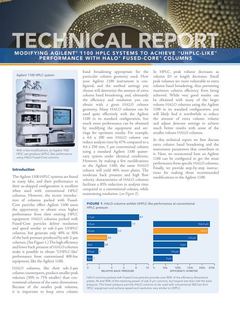
TECHNICAL REPORTMODifying AgileNT ® <strong>1100</strong> <strong>HPLC</strong> SySTeMS TO ACHieve “U<strong>HPLC</strong>-like”perFOrMANCe wiTH HALO ® Fused-Core ® COLuMNS<strong>Agilent</strong> <strong>1100</strong> <strong>HPLC</strong> systemWith a few modifications, an <strong>Agilent</strong> <strong>1100</strong><strong>HPLC</strong> can produce U<strong>HPLC</strong>-like performanceusing HALO Fused-Core columns.IntroductionThe <strong>Agilent</strong> <strong>1100</strong> <strong>HPLC</strong> systems are foundin many labs, and their performance intheir as-shipped configuration is excellentwhen used with conventional <strong>HPLC</strong>columns. However, the recent introductionof columns packed with Fused-Core particles offers <strong>Agilent</strong> <strong>1100</strong> usersthe opportunity <strong>to</strong> obtain even higherperformance from their existing <strong>HPLC</strong>equipment. HALO columns packed withFused-Core particles deliver resolutionand speed similar <strong>to</strong> sub-2-µm U<strong>HPLC</strong>columns, but generate only 40% <strong>to</strong> 50%of the back pressure produced by sub-2-µmcolumns. (See Figure 1.) The high efficiencyand lower back pressure of HALO columnsmake it possible <strong>to</strong> obtain “U<strong>HPLC</strong>-like”performance from conventional 400-barequipment, like the <strong>Agilent</strong> <strong>1100</strong>.HALO columns, like their sub-2-µmcolumn counterparts, produce smaller peakvolumes (50% <strong>to</strong> 75% smaller) than conventionalcolumns of the same dimensions.Because of the smaller peak volumes,it is important <strong>to</strong> keep extra columnband broadening appropriate for theparticular column geometry used. Howyour <strong>Agilent</strong> <strong>1100</strong> instrument is configured,and the method settings youchoose will determine the amount of extracolumn band broadening, and, ultimatelythe efficiency and resolution you canobtain with a given HALO columngeometry. Many HALO columns can beused quite effectively with the <strong>Agilent</strong><strong>1100</strong> in its standard configuration, butmuch more performance can be obtainedby modifying the equipment and settingsfor optimum results. For example,a 4.6 x 100 mm HALO column canreduce analysis time by 67% compared <strong>to</strong> a4.6 x 250 mm, 5 µm conventional columnusing a standard <strong>Agilent</strong> <strong>1100</strong> quaternarysystem under identical conditions.However, by making a few modifications<strong>to</strong> the <strong>Agilent</strong> <strong>1100</strong>, the same HALOcolumn will yield 46% more plates. Themoderate back pressure and high flowvelocity characteristics of HALO columnsfacilitate a 85% reduction in analysis timecompared <strong>to</strong> a conventional column, whilemaintaining resolution. (see Figure 2).Figure 1: HALO columns exhibit U<strong>HPLC</strong>-like performance at conventional<strong>HPLC</strong> pressure1.7 µm1.8 µm2.2 µm2.7 µm Fused-Core 3.43 µm3.5 µm5 µm 122.85.27.78.70 2 4 6 8 10RELATIVE BACK PRESSUREIn <strong>HPLC</strong>, peak volume decreases ascolumn ID or length decreases. Smallpeak volumes are more vulnerable <strong>to</strong> extracolumn band broadening, thus preventingmaximum column efficiency from being<strong>achieve</strong>d. While very good results canbe obtained with many of the largervolume HALO columns using the <strong>Agilent</strong><strong>1100</strong> in its standard configuration, youwill likely find it worthwhile <strong>to</strong> reducethe amount of extra column volumeand adjust detec<strong>to</strong>r settings <strong>to</strong> <strong>achieve</strong>much better results with some of thesmaller volume HALO columns.In this technical report we first discussextra column band broadening and theinstrument parameters that contribute <strong>to</strong>it. Next, we recommend how an <strong>Agilent</strong><strong>1100</strong> can be configured <strong>to</strong> get the mostperformance from specific HALO columns.Finally, we provide step-by-step instructionsfor making those recommendedmodifications <strong>to</strong> the <strong>Agilent</strong> <strong>1100</strong>.5 µm3.5 µm3 µm2.2 µmSub-2 µmHALO0 50k 100k 150k 200k 250kEFFICIENCY: N/METERHALO columns packed with Fused-Core particles provide over 80% of the efficiency (theoreticalplates, N) and 90% of the resolving power of sub-2-µm columns, but require less than half the backpressure. This lower pressure permits HALO columns <strong>to</strong> be used with conventional 400 bar-limit<strong>HPLC</strong> equipment and <strong>achieve</strong> speed and resolution very similar <strong>to</strong> U<strong>HPLC</strong>.
Figure 2: An <strong>Agilent</strong> <strong>1100</strong> modified <strong>to</strong> reduce extra column band broadeningpermits significantly better performance <strong>to</strong> be obtained from HALO columns.Standard configured <strong>Agilent</strong> <strong>1100</strong>Conventional column: 4.6 x 250 mm, 5 μmFlow rate: 1.0 ml/minPressure: 91 barR s = 6.50 minutes 12Standard configured <strong>Agilent</strong> <strong>1100</strong>HALO column: 4.6 x 100 mmFlow rate: 1.0 ml/minPressure: 124 barR s = 5.2R s = 6.3The HALO column delivers a much faster separation compared <strong>to</strong> a conventional columnwhen using a standard configured <strong>Agilent</strong> <strong>1100</strong>, but the resolution is less than expected.When the <strong>Agilent</strong> <strong>1100</strong> is modified <strong>to</strong> reduce extra column band broadening, 46% moreplates and higher resolution are obtained from the same HALO column. The Fused-Coreparticles packed in the HALO column permit a higher flow velocity <strong>to</strong> be used withoutsacrificing resolution or exceeding the pressure limit of the <strong>Agilent</strong> <strong>1100</strong>. The result is areduction in analysis time of 85% while maintaining similar resolution compared <strong>to</strong> theconventional column.Extra Column Band BroadeningN = 25,900N = 16,7000 minutes4<strong>Agilent</strong> <strong>1100</strong> modified <strong>to</strong> reduce extra column band broadeningHALO column: 4.6 x 100 mmFlow rate: 2.0 ml/minPressure: 247 barN = 24,5000 minutes2In liquid chroma<strong>to</strong>graphy the observed peak width (w obs) is comprised of thedispersion (or band broadening) from the chroma<strong>to</strong>graphic process itself (w col)and from dispersion elsewhere in the <strong>HPLC</strong> system (w ec). The relationship can bedescribed by this equation:w 2 obs =w2 col +w2 ecThe observed, column-related, and extra columnrelatedvariances are related similarly,σ 2 = σ 2 +σ 2 obs col ecwhere w = 4σ, σ is the standard deviation of the peakand σ 2 is the peak variance.The <strong>to</strong>tal extra column variance (σ 2 ec) is equal <strong>to</strong>the sum of the variances from the various contribu<strong>to</strong>rs<strong>to</strong> band broadening (assuming all variablesare independent):σ 2 ec= σ 2 injection+ σ 2 tubing + σ 2 flow cell+ variance fromdetec<strong>to</strong>r response time and data rateThe importance of extra column band broadeningcan be assessed relative <strong>to</strong> the peak width or volumeat the retention time or volume for each analyte.In general, the contributions <strong>to</strong> band broadeningand peak volume are inversely proportional <strong>to</strong> theretention time or volume of the analyte, so that extracolumn band broadening is most important for theleast retained analytes in a separation.For a given <strong>HPLC</strong> system configuration, the extracolumn volume, or ECV, is the <strong>to</strong>tal volume outsideof the column that contributes <strong>to</strong> the observed peakvolume. For an <strong>Agilent</strong> <strong>1100</strong> the ECV includes thevolumes associated with the following items:• the injection volume,• the flow path in the au<strong>to</strong>sampler and valve,• the tubing from the au<strong>to</strong>sampler <strong>to</strong> the precolumnheat exchanger,• the precolumn heat exchanger,• the tubing from precolumn heat exchanger <strong>to</strong>the column,• the tubing from the column <strong>to</strong> the detec<strong>to</strong>rflow cell,• the detec<strong>to</strong>r flow cell, and• any volume added by in-line filters, unions, guardcolumns, etc.NOTE: For simplicity, any contributions <strong>to</strong> bandbroadening due <strong>to</strong> fittings and connections areconsidered <strong>to</strong> be negligible with proper choice ofhardware and good practices, and will be ignored.The <strong>to</strong>tal extra column band broadening also includesthe dispersion due <strong>to</strong> electronic signal filteringfrom the detec<strong>to</strong>r. With <strong>Agilent</strong> UV-VIS detec<strong>to</strong>rsthe ChemStation® software Peak Width setting isdirectly related <strong>to</strong> detec<strong>to</strong>r response time, andinversely related <strong>to</strong> data acquisition rate for aparticular detec<strong>to</strong>r type and model. Typically, you canfind the relationships among Peak Width setting,response time, and data rate summarized in atable in the appropriate detec<strong>to</strong>r manual. The largerthe Peak Width setting is, the slower the data rate,and the greater the amount of signal filtering. Conversely,smaller Peak Width settings are associatedwith faster data rates, less signal filtering, and moreshort-term noise. A general recommendation is <strong>to</strong>2
Figure 3: Extra Column Volume, ECVPumpSampleInjectionFlow CellColumnDetec<strong>to</strong>rTABLE A: Standard configured <strong>Agilent</strong> <strong>1100</strong> (as typically shippedfrom <strong>Agilent</strong>)Acceptable configuration for the following HALO columns:4.6 x 150 mm, 4.6 x 100 mm, and 4.6 x 75 mm.Description Part No. Volume (μL)ConnectingTubing and FittingsWasteNeedle seat capillary for standardau<strong>to</strong>sampler 0.17 x 100 mm, GreenOr, needle seat capillary for well-plateau<strong>to</strong>sampler 0.17 x 100 mm, GreenG1313-87101 2.5G1367-87302 2.5SolventReservoirData CollectionIn this schematic of an <strong>HPLC</strong> system, the gold color indicates where extracolumn volume, ECV, is located.Stainless steel tubing from au<strong>to</strong>sampler<strong>to</strong> column compartment heat exchanger0.17 x 180 mm, GreenColumn compartment heat exchanger 3 uLStainless steel tubing from columncompartment heat exchanger <strong>to</strong> column0.17 x 90 mm, GreenStainless steel tubing from column <strong>to</strong>detec<strong>to</strong>r flow cell 0.17 x 380 mm, GreenG1313-87305 4.53.0G1316-87300 2.2G1315-87311 9.4set the detec<strong>to</strong>r Peak Width setting <strong>to</strong> be equal <strong>to</strong> or slightly lessthan the half-height width of the narrowest peak of interest in thechroma<strong>to</strong>gram. In practice, it is wise <strong>to</strong> compare performance (peakwidths, tailing fac<strong>to</strong>rs, signal-<strong>to</strong>-noise ratios) from chroma<strong>to</strong>gramsacquired with several detec<strong>to</strong>r Peak Width settings above and belowthe value for the narrowest peak, in order <strong>to</strong> choose the best settingfor your needs. If the peak width setting is <strong>to</strong>o small, the observedpeak widths will be minimized and peak heights maximized, but thesignal-<strong>to</strong>-noise ratio will suffer due <strong>to</strong> increased baseline noise. If thepeak width setting is <strong>to</strong>o large, baseline noise will be reduced, but thepeaks will be shorter and broader and may begin <strong>to</strong> tail and merge.Several report styles (Performance, Performance and Noise, andExtended Performance) within the Data Analysis View of theChemStation software can help you find an appropriate or optimumsetting for your column and conditions. Fortunately, the datarate is au<strong>to</strong>matically set when you choose the Peak Width settingas just described. Nevertheless, a good rule of thumb is <strong>to</strong>ensure that the data rate is sufficiently fast <strong>to</strong> acquire atleast 20 points across the narrowest peak. As an example, for apeak width at half height of 0.05 min., the 4σ baseline width(1.7 X PW ½) is 5.1 sec., and the data rate should be at least20 points per 5.1 seconds, or ~ 4 Hz.The detec<strong>to</strong>r flow cell (volume and design), the detec<strong>to</strong>r responsetime and the data rate are typically the largest contribu<strong>to</strong>rs <strong>to</strong> bandbroadening. These are the parameters you should optimize firstwhen trying <strong>to</strong> get the most performance from HALO columns.If you are using HALO columns with ID ≤ 3.0 mm, you mayalso have <strong>to</strong> minimize connecting tubing volume, heat exchangervolume, and injection volume.Recommended Instrument Configurations <strong>to</strong> Use withSpecific HALO ColumnsThe smaller the peak volume produced by a column, the moreimportant it is <strong>to</strong> make sure that extra column volume (ECV) doesnot rob you of the resolving power that the column can deliver.Depending on the dimensions of the HALO column you wish <strong>to</strong>use, three different configurations of the <strong>Agilent</strong> <strong>1100</strong> will berecommended; the standard configuration (as shipped from theStandard flow cell for VWD10 mm, 14 μL, 400 barStandard flow cell for DAD/MWD10 mm, 13 µL, 120 barTABLE B: Low ECV configured <strong>Agilent</strong> <strong>1100</strong>G1314-60082 14.0G1315-60022 13.0Total ECV 34.6/35.6Acceptable configuration for the following HALO columns:4.6 x 150 mm, 4.6 x 100 mm, 4.6 x 75 mm, 4.6 x 50 mm, 4.6 x 30mm, 3.0 x 150 mm, 3.0 x 100 mm, and 3.0 x 75 mm.Description Part No. Volume (μL)Needle seat capillary for standardau<strong>to</strong>sampler 0.12 x 100 mm, RedOr, needle seat capillary for well-plateau<strong>to</strong>sampler 0.12 x 150 mm, RedStainless steel tubing from au<strong>to</strong>sampler<strong>to</strong> column compartment heat exchanger0.12 x 180 mm, RedColumn compartment heat exchanger3 uLStainless steel tubing from columncompartment heat exchanger <strong>to</strong> column0.12 x 70 mm, RedStainless steel tubing from column <strong>to</strong>detec<strong>to</strong>r flow cell 0.12 x 180 mm, RedAlternate longer length stainless steeltubing from column <strong>to</strong> detec<strong>to</strong>r flow cell0.12 x 280 mm, RedSemi-micro flow cell for VWD6 mm, 5 μL, 120 barSemi-micro flow cell for DAD/MWD6 mm, 5 μL, 120 barG1313-87103 1.3G1367-87303 1.9G1313-87304 2.33.0G1316-87303 0.9G1313-87304 2.301090-87610 3.6G1314-60083 5.0G1315-60011 5.0Total ECV 14.8/16.73
TABLE C: Ultra-low ECV configured <strong>Agilent</strong> <strong>1100</strong>Acceptable configuration for the following HALO columns:4.6 x 150 mm, 4.6 x 100 mm, 4.6 x 75 mm, 4.6 x 50 mm, 4.6 x 30 mm,3.0 x 150 mm, 3.0 x 100 mm, and 3.0 x 75 mm, 3.0 x 50 mm, 3.0 x 30 mm,2.1 x 150 mm, 2.1 x 100 mm, 2.1 x 75 mm, 2.1 x 50 mm, 2.1 x 30 mm.Description Part No. Volume (μL)Needle seat capillary for standardau<strong>to</strong>sampler 0.12 x 100 mm, RedOr, needle seat capillary for well-plateau<strong>to</strong>sampler 0.12 x 150 mm, RedStainless steel tubing from au<strong>to</strong>sampler<strong>to</strong> low volume heat exchanger0.12 x 180 mm, RedLow volume heat exchanger 1.6 uL(includes connecting tubing <strong>to</strong> column)Stainless steel tubing from column <strong>to</strong>detec<strong>to</strong>r flow cell 0.12 x 180 mm, RedAlternate longer length stainless steeltubing from column <strong>to</strong> detec<strong>to</strong>r flow cell0.12 x 280 mm, RedMicro flow cell for VWD 1 μL, 6 mm 40 barMicro flow cell for DAD/MWD2 μL, 3 mm 40 barTABLE D: Recommended <strong>Agilent</strong> <strong>1100</strong> configurations <strong>to</strong> use withspecific HALO columnsHALO Column Dimensions4.6 x 150 mm Standard, Low-ECV, Ultra-low ECV4.6 x 100 mm Standard, Low-ECV, Ultra-low ECV4.6 x 75 mm Standard, Low-ECV, Ultra-low ECV4.6 x 50 mm Low-ECV, Ultra-low ECV4.6 x 30 mm Low-ECV, Ultra-low ECV3.0 x 150 mm Low-ECV, Ultra-low ECV3.0 x 100 mm Low-ECV, Ultra-low ECV3.0 x 75 mm Low-ECV, Ultra-low ECV3.0 x 50 mm Ultra-low ECV3.0 x 30 mm Ultra-low ECV2.1 x 150 mm Ultra-low ECV2.1 x 100 mm Ultra-low ECV2.1 x 75 mm Ultra-low ECV2.1 x 50 mm Ultra-low ECV2.1 x 30 mm Ultra-low ECVG1313-87103 1.3G1367-87303 1.9G1313-87304 2.3G1316-80002 1.6G1313-87304 2.301090-87610 3.6G1314-60081 1.0G1315-60024 2.0Total ECV 8.5/11.4Notes:• The ChemStation peak width setting is optimized best by carrying out several runsunder method conditions using different settings. One can choose the setting thatgives the best signal <strong>to</strong> noise for all analytes, consistent with observed peak widthand USP tailing fac<strong>to</strong>rs using Performance and Noise and Extended Performancereports from the Data Analysis view of the <strong>Agilent</strong> ChemStation software• In the au<strong>to</strong>sampler, replacing the 0.17 x 100 mm needle seat capillary (<strong>Agilent</strong>part number G1313-87101, 2.5 µL) with the 0.12 x 100 mm seat capillary (<strong>Agilent</strong>part number G1313-87103, 1.1 µL) will reduce ECV and improve systemefficiency slightly.<strong>Agilent</strong> <strong>1100</strong> Configurationfac<strong>to</strong>ry), a low ECV configuration, and an ultra-low ECV configuration.See Tables A, B and C for the three different <strong>Agilent</strong> <strong>1100</strong> configurationswe recommend for specific HALO column dimensions.Modifying Your <strong>Agilent</strong> <strong>1100</strong> SystemModifying your <strong>Agilent</strong> <strong>1100</strong> system from the standard configuration<strong>to</strong> either the low ECV or ultra-low ECV configuration is quite simple,once you have the parts on hand. The <strong>Agilent</strong> part numbers needed <strong>to</strong>make the modifications are listed in Tables A, B and C. Substitutionof similar sized capillary tubing from a source other than <strong>Agilent</strong> isgenerally okay, but we recommend that the replacement low volumeheat exchanger and detec<strong>to</strong>r flow cells come from <strong>Agilent</strong> <strong>to</strong> ensurecompatibility.Step 1: Replace the standard capillary tubing (0.17 x 180 mm, green,G1313-87305) connecting the au<strong>to</strong>sampler valve <strong>to</strong> the heat exchangerin the column compartment with the low volume capillary tubing(0.12 x 180 mm, red, G1313-87304). For ultra-low ECV configurationconnect the outlet of the capillary tubing <strong>to</strong> the inlet union of thelow volume heat exchanger (G1316-80002). Position the low volumeheat exchanger in one of the wells of the column compartment heatexchanger block, and secure it using one of the column clips as needed.See Figure 4.Step 2: Replace the standard capillary tubing (0.17 x 90 mm, green,G1316-87300) connecting the heat exchanger <strong>to</strong> the column withthe low volume capillary tubing (0.12 x 70 mm, red, G1316-87303).For the ultra-low ECV configuration, connect the outlet tubing ofthe low volume heat exchanger (G1316-80002) directly <strong>to</strong> the columninlet using an appropriate stainless steel, PEEK or polyke<strong>to</strong>ne fitting.See Figure 4.Step 3: Replace the standard capillary tubing (0.17 x 380 mm, green,G1315-87311) connecting the column <strong>to</strong> the detec<strong>to</strong>r flow cell withthe low volume capillary tubing (0.12 x 180 mm, red, G1313-87304)or the alternate longer capillary tubing (0.12 x 280 mm, red,01090-87610). See Figure 4. Note: Do not connect the tubing <strong>to</strong> thedetec<strong>to</strong>r until the column and tubing have been flushed.Step 4: Prime the instrument and flush the tubing and columnwith either 100% methanol or ace<strong>to</strong>nitrile. Some people find they<strong>achieve</strong> faster equilibration by first flushing the capillary tubing beforeconnecting the column and flushing it.Step 5: Replace the standard detec<strong>to</strong>r flow cell with either a semimicroflow cell (low ECV) or a micro flow cell (ultra-low ECV).See Figure 5.Step 6: Connect the capillary tubing coming from the outlet ofthe HALO column <strong>to</strong> the detec<strong>to</strong>r flow cell. For diode-array andmultiwavelength detec<strong>to</strong>rs the capillary tubing is normally connected<strong>to</strong> a zero dead volume union, which then is connected <strong>to</strong> thecapillary tubing connected in<strong>to</strong> the flow cell body. For 2.1 mm HALOcolumns in shorter lengths (30, 50, 75 mm) it is beneficial <strong>to</strong> connectthe column directly <strong>to</strong> the capillary inlet tubing of the flow cell <strong>to</strong> minimizeextracolumn volume and extra connections. It may be necessary<strong>to</strong> stack the column compartment directly above the DAD/MWDdetec<strong>to</strong>r in such situations.Step 7: Pump 100% methanol or ace<strong>to</strong>nitrile through the tubing,column and the detec<strong>to</strong>r flow cell for ~ 5 minutes or until you observestable pressure and baseline.You should observe a flat baseline at 25-50 mAUFS with a UVdetec<strong>to</strong>r, and can now proceed <strong>to</strong> equilibrate your column with yourmobile phase and begin running samples.4
Figure 4: Replace standard capillary tubing (0.17 mm, green) withlow volume capillary tubing (0.12 mm, red).Step 1: Replacecapillary tubing fromsample injec<strong>to</strong>r valve<strong>to</strong> heat exchanger(3 μL) in the columncompartment.Step 2: Replacecapillary tubingconnecting the heatexchanger <strong>to</strong> thecolumn.Step 3: Replacecapillary tubingconnecting thecolumn <strong>to</strong> thedetec<strong>to</strong>r flow cell.band after injection and before the column is usually minimized oreliminated, if the injection volume is not <strong>to</strong>o large and the startingmobile phase is not <strong>to</strong>o strong. However, it continues <strong>to</strong> be important<strong>to</strong> minimize extra column band broadening after the column(tubing and flow cell volume, and Chemstation Peak Width setting)for gradient separations when using low-volume, high efficiencyHALO columns.If you plan <strong>to</strong> only run gradient separations with your <strong>Agilent</strong><strong>1100</strong>, you may be able <strong>to</strong> skip Steps 1 and 2 when modifyingthe equipment.For gradient separations the delay volume is also important becauseit imposes an isocratic hold <strong>to</strong> the start of the gradient program,such that the desired mobile phase composition reaches the columnat a time later than programmed by a fac<strong>to</strong>r of V d/F, where V dis thedelay volume and F is the volumetric flow rate. For a discussion ofthe translation of gradient methods please see our Quick Tips Guidehttp://www.mac-mod.com/QTpdf.ConclusionFigure 5: Replace standard detec<strong>to</strong>r flow cell with either asemi-micro flow cell (low ECV configuration) or a micro flow cell(ultra-low ECV configuration).Step 5: Removestandard detec<strong>to</strong>rflow cell and replacewith a semi-microflow cell or a microflow cell.Figure 6 illustrates the benefits of modifying an <strong>Agilent</strong> <strong>1100</strong> <strong>to</strong>an ultra-low ECV configuration. Compared <strong>to</strong> a conventionalcolumn, analysis time is reduced by over 90% while resolutionis maintained. This performance compares favorably with U<strong>HPLC</strong>,but is accomplished with a conventional <strong>Agilent</strong> <strong>1100</strong> quaternarysystem by making a few simple, and inexpensive, modifications <strong>to</strong>the equipment.Figure 6: An ultra-low ECV configured <strong>Agilent</strong> <strong>1100</strong> using aHALO column provides performance that compares favorably <strong>to</strong>U<strong>HPLC</strong> systems.Gradient SeparationsAll of the considerations and recommendations about reducingextra column band broadening which have been made thus far inthis technical report have dealt with isocratic separations. If you aredeveloping a new gradient method or translating an existing gradientmethod <strong>to</strong> a HALO column, the most important parameters arethe same ones that have been discussed for isocratic separations.However, there are two major differences.1. The extra column volume before the column is less importantthan the extra column volume after the column when using agradient, and,2. the delay volume (system volume from the point where solvents Aand B are mixed up <strong>to</strong> the column itself ) is important because it is amajor contribu<strong>to</strong>r <strong>to</strong> the “hold” time at the beginning of a gradient.Extra column volume before the column is less important for gradientseparations, because there will be a refocusing of the analytes atthe head of the column (unless pre-elution of polar analytes occurs)in a gradient separation. Consequently, any dispersion of the sampleConditionsColumn: HALO C18, 3.0 x 50 mmMobile Phase: 35% ace<strong>to</strong>nitrile <strong>to</strong>90% ace<strong>to</strong>nitrile in 1 minuteFlow Rate: 2.0 mL/min.Column Temperature: 40º CPressure: 304 bar —> 167 barResponse Time: < 0.125 sec1234Sample:1. Ace<strong>to</strong>phenone2. Propiophenone3. Butyrophenone4. Benzophenone5. Valerophenone6. Hexanophenone7. Heptanophenone8. Octanophenone1.5 minutes7 80 minutes2An ultra-low ECV configured <strong>Agilent</strong> <strong>1100</strong> quarternary system using a highefficiency HALO column (Fused-Core particles) separates these 8 alkylphenonesin 90 seconds with ample resolution between all peaks. This speedand resolution compare favorably <strong>to</strong> the performance reported bychroma<strong>to</strong>graphers using U<strong>HPLC</strong> equipment and sub-2 μm columns. Thepressure generated by the HALO column is well within the acceptableoperating limits of the <strong>Agilent</strong> <strong>1100</strong>.565
www.advanced-materials-tech.comLC501®HALO and Fused-Core are registered trademarks of Advanced Materials Technology, Inc.®<strong>Agilent</strong> and ChemStation are registered trademarks of <strong>Agilent</strong> Technologies, Inc.