0150-0241B Philips ProBridge User Manual.doc - UTCFS Global ...
0150-0241B Philips ProBridge User Manual.doc - UTCFS Global ...
0150-0241B Philips ProBridge User Manual.doc - UTCFS Global ...

Create successful ePaper yourself
Turn your PDF publications into a flip-book with our unique Google optimized e-Paper software.
© 2004 GE SecurityAll Rights Reserved.Any GE Security software supplied withGE Security products is proprietary andfurnished under license and can be used orcopied only in accordance with the terms ofsuch license.This <strong>doc</strong>ument contains proprietaryinformation that is protected by copyright. Nopart of this <strong>doc</strong>ument may be reproduced ortransmitted in any form or by any meanswithout the prior written permission ofGE Security.The information contained in this <strong>doc</strong>ument issubject to change without notice. GE Securityin keeping pace with technological advances,is a company of product innovation. Therefore,it is difficult to ensure that all informationprovided is entirely accurate and up-to-date.GE Security accepts no responsibility forinaccuracies or omissions and specificallydisclaims any liabilities, losses, or risks,personal or otherwise, incurred as aThis equipment has been tested andfound to comply with the limits for aClass A digital device, pursuant topart 15 of the FCC Rules. Theselimits are designed to providereasonable protection againstharmful interference when theequipment is operated in acommercial environment. Thisequipment generates, uses, and canradiate radio frequency energy and,if not installed and used inaccordance with the instructionmanual, may cause harmfulinterference to radiocommunications.You are cautioned that any changesor modifications not expresslyapproved by the party responsiblefor compliance could void the user'sauthority to operate the equipment.consequence, directly or indirectly, of the use or application of any of the contents of this<strong>doc</strong>ument.For the latest product specifications, visit GE Security online at www. GE-Security.com orcontact your sales representative.For technical support before and after installation, call 800-469-1676.Technical support is available 24 hours a day, 7 days a week.Call: Tech Support 800-469-1676 (6 A.M. – 5 P.M. PST Monday through Friday)Tech Support 541-740-3589 (all other times)Main 800-343-3358 or 541-754-9133Fax: Tech Support 541-752-9096 (available 24 hours a day)Main 541-754-7162Web: www.GE-Security.com<strong>0150</strong>-<strong>0241B</strong> / May 2004<strong>Philips</strong> <strong>ProBridge</strong> 2 <strong>0150</strong>-<strong>0241B</strong>
Table of Contents1 <strong>Philips</strong> <strong>ProBridge</strong> ........................................................... 41.1 <strong>Philips</strong> <strong>ProBridge</strong> Description.................................................................. 41.2 Compatibility ............................................................................................. 41.3 Installation Environment........................................................................... 41.4 Power........................................................................................................ 51.5 Installation Steps Summary ..................................................................... 61.6 Connection Diagrams............................................................................... 72 Cable Specifications ..................................................... 83 Troubleshooting............................................................. 94 Unit Settings................................................................ 104.1 Configuring <strong>ProBridge</strong> Jumpers ............................................................ 105 Specifications.............................................................. 126 Appendix...................................................................... 136.1 RS-485 Addressing and Connections................................................... 136.2 Philip AutoDome Addressing................................................................. 146.3 Using Kalatel Keypads........................................................................... 156.4 AUX Operations...................................................................................... 166.5 Preset Operations................................................................................... 167 Warranty Information .................................................. 187.1 Factory Service....................................................................................... 187.2 Factory Address ..................................................................................... 187.3 Warranty.................................................................................................. 18<strong>Philips</strong> <strong>ProBridge</strong> 3 <strong>0150</strong>-<strong>0241B</strong>
1 <strong>Philips</strong> <strong>ProBridge</strong>1.1 <strong>Philips</strong> <strong>ProBridge</strong> DescriptionThe Kalatel CBR-PB2-PHILIPS is a specific <strong>ProBridge</strong> unit for interfacing theDVMRe family of digital video multiplex/recorders and providing local keyboardcontrol via a CBR-KB3 or KTD-405 keypad to a <strong>Philips</strong> AutoDome.Kalatel Components:(1) CBR-PB2-PHILIPS <strong>ProBridge</strong>. This product includes:• (1) CBR-PB2-PHILIPS <strong>ProBridge</strong> unit.• (2) P/N 4310-0034: RJ45 to RJ45 cable. Connects the <strong>ProBridge</strong> and aCBR-KB3 or KTD-405 to the RS-485 Network. These cables are 6’ inlength.• (1) P/N 4310-0047B: Cable from PB2 to <strong>Philips</strong> Data Converter Unit(LTC 8780).• (1) P/N 4010-0007: 12VDC 120VAC Power Supply or(1) P/N 4010-0008: 12VDC 220VAC Power Supply.• (1) P/N <strong>0150</strong>-0241A: Product Overview and Installation <strong>Manual</strong>.<strong>Philips</strong> Components:• (1) <strong>Philips</strong> Data Converter Unit (LTC 8780).• (1) <strong>Philips</strong> AutoDome.1.2 CompatibilityThe CBR-PB2-PHILIPS is compatible with all Kalatel DVMRe digital videomultiplex/recorders equipped with RS-485 network capabilities exceptinstallations with a CBR-KB1 Keypad.Compatible units include the Kalatel DVMRe digital video units and variousKalatel Multiplexer models (Simplex, Triplex, Matrix). Please check thespecifications of the particular Kalatel product for RS-485 network support.1.3 Installation EnvironmentPower: Ensure that the installation site’s AC power is stable and within the ratedvoltage of the external power supply. If the site’s AC power is likely to havespikes or dips, use power line conditioning or an Uninterruptible Power Supply.<strong>Philips</strong> <strong>ProBridge</strong> 4 <strong>0150</strong>-<strong>0241B</strong>
Temperature: Observe the unit’s ambient temperature specifications whenchoosing a location for the unit. Extremes of heat or cold beyond the specifiedoperating temperature limits may cause the unit to fail. Do not install this unit ontop of other hot equipment.Moisture: Do not expose the unit to rain or moisture. Moisture can damageinternal components. Do not install this unit near sources of water.RS485 Limitations: Total length of the RS-485 network is limited to 3000’.1.4 PowerThe <strong>ProBridge</strong> is furnished with a power supply (110 or 240 VAC). Do not useany other power supply with this product. The manufacturer accepts noresponsibility for damage caused by the use of any other power supply.Make sure installation is complete and all connections are made before applyingpower to the unit.4310-0007 120VAC Power SupplyVoltage: 120 Volt ACTolerance: ±10%Frequency: 60 HzPower Supply InputPower Supply OutputVoltage: 12 Volt DCCurrent: 110mAPower: 1.3 WattsConnector: 2.1mm female barrel. Center Positive4310-0008 220VAC Power SupplyVoltage: 220 Volt ACTolerance: ±10%Frequency: 50 HzPower Supply InputPower Supply OutputVoltage: 12 Volt DCCurrent: 110mAPower: 1.3 WattsConnector: 2.1mm female barrel. Center Positive<strong>Philips</strong> <strong>ProBridge</strong> 5 <strong>0150</strong>-<strong>0241B</strong>
1.5 Installation Steps SummaryCarefully and completely read the manuals for each piece of equipmentbefore attempting to install and connect this equipment.Before you start connecting other optional accessory equipment to yoursystem, make sure that all, power, video, VCR, and monitor connections arecompleted, and everything is working correctly.Wire the telemetry equipment according to that unit’s installation instruction.Use the internal diagnostic testing capabilities of the telemetry receiver toverify that the power and connections to the lens and motors are correct, andfunction properly.Using the Diagram on the following page, connect the equipment in thefollowing order:1. Connect the CBR-PB2-PHILIPS to the Kalatel unit (DVMReSimplex, DVMRe Triplex, DVMRe Matrix) via RS-485 port using theRJ45 to RJ45 cable. The maximum total distance allowed on theRS-485 data line (without signal amplification or modems) is 3,000feet (1,000 meters). A 100-ohm terminator is required at each endof the RS-485 line.2. Connect the CBR-KB3 or KTD-405 keypad to the Kalatel unit(DVMRe Simplex, DVMRe Triplex, DVMRe Matrix) via RS-485 portusing the RJ45 to RJ45 cable.3. Supply power to the Kalatel unit first and the CBR-PB2-PHILIPSsecond using the supplied AC to 12 VDC adapter. Via the SetupMenus for the Kalatel unit set the RS-485 network address to theappropriate number (see the Appendix for RS-485 addressing).4. Using the provided cable, connect from the <strong>ProBridge</strong> RCVR/DRVRport to the <strong>Philips</strong> Data Converter Unit (LTC 8780). See the <strong>Philips</strong>Data Converter Unit’s (LTC 8780) installation manual forinformation on connecting the LTC 8780 to the AutoDome.5. Set the ID addresses for the <strong>Philips</strong> Dome according to the tablelater in this manual.6. Via a networked connected PC with WaveReader software,connect to the DVMRe unit and confirm proper control andoperation of the PTZ unit.NOTEPlease note, that whenever the <strong>ProBridge</strong> is used with a KTD-405the KB3 PTZ Protocol option in the KTD-405 menu must be set toYES. See Supervisor Programming in the KTD-405 manual.<strong>Philips</strong> <strong>ProBridge</strong> 6 <strong>0150</strong>-<strong>0241B</strong>
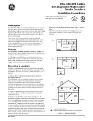
1 1 75 2 19 2513 2 92 1 86 2 210 2614 3 03 1 97 2 311 2715 3 1ALT4 2 08 2 412 2816 3 2B C D E{ F}#AUXAUXAUXAUX41 231.6 Connection DiagramsThis drawing depicts one <strong>Philips</strong> AutoDome connected via an RS485/422network to a Kalatel DVMReTriplex unit, that provides remote PTZ controlover Ethernet via WaveReader software, and a CBR-KB3 or KTD-405keypad.<strong>Philips</strong> AutoDomeDB9-FLTC 8780Data Converter Unit<strong>Philips</strong><strong>ProBridge</strong>4310-0047B CableRJ45RJ45MUX/DVMRRCVR/DVRRJ454310-0034B CableKB3/KTD-4054310-0034B CableRJ45DVMRe TriplexRJ45<strong>Philips</strong> <strong>ProBridge</strong> 7 <strong>0150</strong>-<strong>0241B</strong>
3 TroubleshootingIf you are unable to verify control of the PTZ camera, please do the following:1. Check that each device is properly powered.2. Check that all cables and cable connections are correct.3. Verify that the Dome addresses and Unit ID are correct.4. If the interface still does not work correctly contact Technical Support.<strong>Philips</strong> <strong>ProBridge</strong> 9 <strong>0150</strong>-<strong>0241B</strong>
4 Unit Settings4.1 Configuring <strong>ProBridge</strong> JumpersThe unit ships from the factory with the correct settings for most applications andshould not require the installer to open the unit and change the jumper settings.However, for trouble shooting purposes we have included the default jumpersettings.Opening The <strong>ProBridge</strong>Place the <strong>ProBridge</strong> unit face down.Using a small Phillips screwdriver,carefully remove the screws locatednear each corner of the unit. Oncethe screws have been removed, liftthe cover to detach.Identifying The JumpersWith the cover removed, orient theunit as shown here. There are twosets of configurable jumpers. Oneset, located on the left side of theboard, controls how the unitcommunicates (JP2, JP3, JP4 andJP5). The other set, located at thebottom of the board (P6, twelve pinheader) determines specificconfiguration elements forequipment interfacing.<strong>ProBridge</strong> Circuit Board<strong>Philips</strong> <strong>ProBridge</strong> 10 <strong>0150</strong>-<strong>0241B</strong>
Default Jumper SettingsThe default jumper settings are listed below:PIN # DEFAULT STATUSJP2RS485 PositionJP3RS485 PositionJP4RS485 PositionJP5RS232 PositionP6 Pin 1Not InstalledP6 Pin 2Not InstalledP6 Pin 3InstalledP6 Pin 4Not InstalledP6 Pin 5Not InstalledP6 Pin 6Not InstalledP6 Pin 7Not InstalledP6 Pin 8Not InstalledP6 Pin 9Not InstalledP6 Pin 10Not InstalledP6 Pin 11Not InstalledP6 Pin 12Not Installed<strong>Philips</strong> <strong>ProBridge</strong> 11 <strong>0150</strong>-<strong>0241B</strong>
5 SpecificationsHousingDimensions(W x L x H)PhysicalPlastic enclosure.Nominal Weight 4.8 oz (136 g)Shipping WeightColor1.5 x 4.4 x 3.3 in. (38 x 112x 84 mm)1 lb (453 g) packaged, includingthe external AC power supply andmanual.Light gray.TemperatureRelative HumidityEnvironmental0 to 40 °C, operating.90%, non-condensing.ElectricalAC PowerExternal AC power supply included.Voltage Range: 110 to 240 VAC + 10%Current:200 mADC PowerDC jack, positive center.Power Supply Voltage: 12 VDCCurrent:110 mAPower:1.3 WNOTEAll specifications are subject to change without notice. Kalatelbelieves that all specifications are correct, however no liability isassumed for omissions or errors.<strong>Philips</strong> <strong>ProBridge</strong> 12 <strong>0150</strong>-<strong>0241B</strong>
6 Appendix6.1 RS-485 Addressing and ConnectionsNOTEThe <strong>Philips</strong> <strong>ProBridge</strong> (CBR-PB2-PHILIPS) is not an addressabledevice and requires no user settings. The device simply acts as aninterpreter, translating the remote telemetry commands into aformat useable by the P/T/Z controller.Each camera input, whether a fixed camera or a Pan/Tilt/Zoom (P/T/Z) unit, isconnected to a Kalatel unit input. The Kalatel unit has an RS-485 networkaddress, and so does the P/T/Z camera receiver. This address determineswhen the telemetry receiver responds to commands sent over the RS-485data line. Consult the PTZ installation manual for specific instructions onsetting these addresses.NOTEThe CBR-PB2-PHILIPS can be used in conjunction with multipleKalatel units, and/or keypads controlling the domes and the Kalatelunits. Since the <strong>ProBridge</strong> unit is a terminated device, care shouldbe used when using this unit in a mixed application.The RS-485 network is a multi-drop wiring configuration of maximum length3,000 feet (1000 meters). RJ45 cable and RJ45 connectors are used formost hookups (see the installation/connection diagram). Some equipmentmanufactured by Kalatel may use flying leads, terminal blocks, or other typesof connections.Most units have looping RS-485 network connectors. Either socket can beused. Do not use third-party RS-485 equipment without first consultingKalatel Technical Support for information on compatibility with other Kalatelequipment.RS-485 Wire Specification#24 AWG, twisted pair with shield (2-wire).Less than 16 pF per foot, nominal.Less than 25 ohms per 100 foot, nominal.2-wire: Belden 98424-wire: Belden 9844<strong>Philips</strong> <strong>ProBridge</strong> 13 <strong>0150</strong>-<strong>0241B</strong>
6.2 Philip AutoDome AddressingThe <strong>Philips</strong> AutoDome can be addressed from 1 to 9998. The CBR-PB2-PHILIPS <strong>ProBridge</strong> can control camera addresses from 1 to 9998, howeverthe CBR-KB3 keyboard can control cameras from 1 to 1024. WaveReadersoftware can only control cameras from 1 to 8160.Camera MappingRS485 Network Address Camera Address AutoDome Address001 1 - 32 0001 – 0032002 1 – 32 0033 – 0064003 1 – 32 0065 – 0096004 1 – 32 0097 – 0128005 1 – 32 0129 – 0160006 1 – 32 0161 – 0192007 1 – 32 0193 – 0224008 1 – 32 0225 – 0256009 1 – 32 0257 – 0288010 1 – 32 0289 – 0320011 1 – 32 0321 – 0352012 1 – 32 0253 – 0384013 1 – 32 0385 – 0416014 1 – 32 0417 – 0448015 1 – 32 0449 – 0480016 1 – 32 0481 – 0512017 1 – 32 0513 – 0544018 1 – 32 0545 – 0576019 1 – 32 0577 – 0608020 1 – 32 0609 – 0640021 1 – 32 0641 – 0672022 1 – 32 0673 – 0704023 1 – 32 0705 – 0736024 1 – 32 0737 – 0768<strong>Philips</strong> <strong>ProBridge</strong> 14 <strong>0150</strong>-<strong>0241B</strong>
RS485 Network Address Camera Address AutoDome Address025 1 – 32 0769 – 0800026 1 – 32 0801 – 0832027 1 – 32 0833 – 0864028 1 – 32 0865 – 0896029 1 – 32 0897 – 0928030 1 – 32 0929 – 0960031 1 – 32 0961 – 0992032 1 – 32 0993 – 1024-- -- --255 1 – 32 8129 – 8160NOTE<strong>Philips</strong> AutoDome Addresses are calculated as follows:<strong>Philips</strong> AutoDome Address = Camera Address + 32 X (Network Address – 1)<strong>Philips</strong> Data Converter Unit Switch SettingSet the switches on the LTC8780 as follows:S101: Switches 1, 3, and 4 set to OFF. Switch 2 set to ON.S102: Switches 1 –3 set on ON, switch 4 set to OFF.See <strong>Philips</strong> LTC8780 manual for details.6.3 Using Kalatel KeypadsKeyboards (CBR-KB3/J and KTD-405) are typically used to provide initialconfiguration of the <strong>Philips</strong> AutoDome for setting addresses and presets.NOTEIn some specific cases keyboards may be used in conjunction withthe CBR-PB2-PHILIPS units where multiple Kalatel units are beingcontrolled via one or more local Keyboard. Available keyboardsare only involved when an RS-485 is configured with CBR-KB2/J,CBR-KB3/J and KTD-405 Keyboards. Please contact TechnicalSupport for additional instructions concerning these specialinstallations.<strong>Philips</strong> <strong>ProBridge</strong> 15 <strong>0150</strong>-<strong>0241B</strong>
ALT Key Shift Key Aux Keys#ALTAUX1AUX2AUX3AUX41 1 72 1 83 1 94 2 05 2 16 2 27 2 38 2 49 2 510 2 611 2 712 2 8B C D E13 2 914 3 015 3 116 3 2{ F }Keyboard LayoutPreset Key6.4 AUX OperationsThe remote keyboard has 8 AUX function keys that can be assigned to dosome <strong>Philips</strong> AutoDome features as follows:Remote KeypadAux1 On/OffAux2 On/OffAux3 On/OffAux4 On/OffAux5 On/OffAux6 On/OffAux7 MomentaryAux8 MomentaryFuctionScanAuto PanContinuous Playback A Start/StopContinuous Playback B Start/StopRecord Sequence ARecord Sequence BPreset Tour Start. Move Joystick to stop.Start Advanced Menu Mode.6.5 Preset OperationsThe <strong>Philips</strong> AutoDome can store up to 99 preset operations (1-99). With theremote keyboard, the number of presets that can be set up is 32 (1-32). WithWaveReader, the number of presets that can be set up is 16 (1-16).<strong>Philips</strong> <strong>ProBridge</strong> 16 <strong>0150</strong>-<strong>0241B</strong>
Preset Setup for CBR-KB KeyboardTo set a new Preset position:1. Move the camera to the desired position by using the joystickor arrow keys.2. Press Preset key twice. The LCD will display: “Set PreshotNumber?” Select camera key number 1 to 16 (17 to 32 withShift key turned on) to set the preset number from 1 to 32.3. Verify by calling up that preset number: Move to anotherposition then press Preset key once. The Keyboard LCD willdisplay: “Go to Preshot Number?” Select the preset number togo to that preset position.To clear an existing Preset position:1. Press the Preset key twice. The Keyboard LCD will display:“Set Preshot Number?” Select the camera key to the desiredpreset number. The Dome will go to that existed Presetposition and clear this preset.2. Move the Dome to the new position by using the joystick orarrow keys.3. Repeat step 1: Press Preset key twice. The KB3 LCD willdisplay: “Set Preshot Number?” Select the camera key to thepreset number. Now, the new preset position is stored.4. Verify by calling up that preset number: Move to anotherposition then press Preset key once. The KB3 LCD will display:“Go to Preshot Number?” Select the preset number to go tothat preset position.Preset Setup WaveReaderTo set a new Preset position:1. Navigate the camera to the desired location, select thedesired preset from the drop down list box, then click Set.2. To send the camera to the desired preset, select thepreset from the drop down list box, then click Go To.<strong>Philips</strong> <strong>ProBridge</strong> 17 <strong>0150</strong>-<strong>0241B</strong>
7 Warranty Information7.1 Factory ServiceIf the unit requires factory service, contact the dealer who supplied the unit to you for thecorrect procedures on returning the unit to the factory or the nearest factory service center.If the dealer is not available, contact the manufacturer of the unit as detailed below andrequest a Return Material Authorization number (RMA). The unit’s serial number must beprovided before an RMA number can be issued. Units returned to the factory for servicemust have freight and insurance prepaid, and must show the RMA number clearly on allshipping <strong>doc</strong>uments. The failure symptoms must be clearly described by the operator andenclosed with the unit together with a copy of the original supplier’s invoice. Failure tocomply with these instructions will delay service of the unit, and may result in the unit notbeing accepted by the Repair Center.7.2 Factory AddressGE SecurityAttention: Repair Center3050 Red Hill Ave.Costa Mesa, CA 92626United States of AmericaTelephone: 800-343-3358 (7:00 AM to 4:30 PM, Pacific Time)In Oregon: 541-754-9133Fax: 541-754-7162 (24 hours a day)For warranty information, see the following page.7.3 WarrantyGE Security warrants all of its equipment for three years from the date of purchase. Thiswarranty covers any defects in materials and workmanship. Equipment failures that are dueto improper installation, modification, abuse, or acts of nature will not be covered by thiswarranty. The repair department will evaluate all equipment returned for repair to determinewarranty coverage. The Tech Support Manager will resolve any questions that may ariseduring evaluation to make a final determination.The warranty specifically covers any defects in material and workmanship and does notcover equipment that has been abused, damaged, or modified.For all warranty repairs, GE Security will cover all costs, including parts, labor, andshipping. Repaired equipment will be returned via the same method of shipment in which itwas received. If a customer requests a faster return shipment, the difference will becharged.For all non-warranty repairs, the customer will be billed for parts, labor, and shipping.Labor will be billed in half-hour increments.<strong>Philips</strong> <strong>ProBridge</strong> 18 <strong>0150</strong>-<strong>0241B</strong>
Note: Customers requesting an estimate prior to repair will be notified by phone. If theycannot be reached, they will be notified by fax. If we are unable to reach the contact personfor repair authorization after one phone attempt and two fax attempts, the equipment will bereturned without being repaired. We will hold equipment no longer than two weeks.Advance Replacement PolicyWhen an advance replacement is required, we will send the customer replacementequipment from our stock and receive the returned product in exchange. The receivedequipment will be evaluated and the repair department will determine whether it is awarranty replacement. If it is non-warranty, see our repair policy above for details. Thefollowing guidelines will be used for all advance replacements:• Fewer than 45 days from purchase, GE Security will replace the product with newequipment.• From 45 days to 1 year from purchase, GE Security will replace the product withrefurbished equipment.• From 1 year to 3 years from purchase, the product must be sent in for repair.Advance replacements will be sent for a fee of $100.If you have questions about this policy, please contact GE Security’s RMA Departmentat 800-469-1676.<strong>Philips</strong> <strong>ProBridge</strong> 19 <strong>0150</strong>-<strong>0241B</strong>