SSP 275 Phaeton Air - Volkspage
SSP 275 Phaeton Air - Volkspage
SSP 275 Phaeton Air - Volkspage
- No tags were found...
Create successful ePaper yourself
Turn your PDF publications into a flip-book with our unique Google optimized e-Paper software.
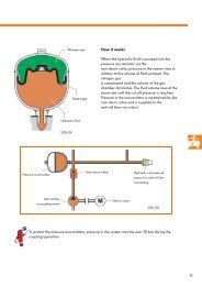
Design and function<strong>Air</strong> drierThe air in the pressure system must bedehumidified to avoid problems with– corrosion and– freezingdue to condensation water.Since the air drier is only regenerated viadischarged air, the compressor must not be usedto fill other vessels with compressed air.Water or moisture in the system are signs that theair drier or system has malfunctioned.An air drier is used to dehumidify the air.The air drier uses a regenerative process, i.e.the air compressed in the self-levellingsuspension system is ducted through a silicategranulate and dried in the process.This granulate is able to absorb atmospherichumidity amounting to over 20 % of its naturalweight, depending on temperature.If the dried air is discharged again due tooperating requirements (to lower the springs), itflows back through the granulate and extractsfrom it the moisture which it has absorbed whenit is discharged to atmosphere.As a result of this regenerative process, the airdrier requires no maintenance.It is not subject to a replacement interval.<strong>Air</strong> drier withgranulate filling<strong>275</strong>_033<strong>275</strong>_04548
Design and functionPneumatic diagram1 - Pneumatic drain valve2 - Electric drain valve N1113 - Silencer/filter4 - Compressor V665 - Non-return valve 16 - <strong>Air</strong> drier7 - Drain restrictor8 - Non-return valve 39 - Non-return valve 210 - Pressure sender G29111 - Pressure accumulator valve N31112 - Suspension strut valve, rear left N15013 - Suspension strut valve, rear right N15114 - Suspension strut valve, front left N14815 - Suspension strut valve, front right N14916 - Pressure accumulator17 - Strut, rear left18 - Strut, rear right19 - Strut, front left20- Strut, front rightJ403J1971 23485 6 9710p11 12 13 14 151617 18 19 20<strong>275</strong>_06550
Solenoid valvesAll in all, the air suspension has six solenoidvalves.The drain valve N111 together with the pneumaticdrain valve form a functional unit which isintegrated in the drier housing. The drain valveN111 is a 3/2 way valve and is de-energisedwhen closed.The pneumatic drain valve has two tasks: to limitpressure and to maintain residual pressure.Together with the self-levelling suspensionpressure accumulator valve N311, thefour air spring valves N148, N149, N150 andN151 are combined in the solenoid valve block.The valves in the solenoid valve block aredesigned as 2/2 way valves and are deenergisedwhen closed.The pressure on the air spring side/accumulatorside acts in the closing direction.To avoid confusion when connecting the pressurelines, the pressure lines are colour coded.The matching connections on the solenoid valveblock are also colour coded.Compressorconnectionfront left/redPressure accumulator/lilacElectricalconnectionfront right/greenrear left/blackrear right/blueSolenoid valve block withN148, N149, N150, N151and N311<strong>275</strong>_06651
Design and functionCompressor temperature sender G290(overheating protection)Compressor temperature senderTo ensure system availability, compressortemperature sender G290 is attached to thecompressor cylinder head.The control unit J197 shuts the compressor downand inhibits starting when a max. permissiblecompressor temperature is exceeded.<strong>275</strong>_067Self-levelling suspension system pressuresender G291The pressure sender G291 is integrated in thevalve unit and monitors pressure in the pressureaccumulator and the air springs. Information onaccumulator pressure is required to makeplausibility checks on the up-control functionsand perform self-diagnosis. The individualpressures of the air springs and the pressureaccumulator can be determined by activating thesolenoid valves accordingly.Self-levelling suspensionpressure senderpSolenoid valveThe individual pressures are measured whileevacuating or filling the air springs or thepressure accumulator. The pressures determinedin this way are stored and updated by the controlunit.Accumulator pressure is additionally determinedevery six minutes (updated) during vehicleoperation.G291 generates a voltage signal proportional tothe pressure.PressureaccumulatorSolenoid valveblock<strong>275</strong>_06852
Vehicle level senders G76, G77, G78, G289(level sensors)The vehicle level senders are so-called wheelangle sensors. Changes in the level of the vehiclebody are registered and converted to angularchanges by means of the coupling rodkinematics.The signal output provides an angleproportionalPWM (pulse-width modulated)signal for the self-levelling suspension.The wheel angle sensor used operates accordingto the induction principle.The four level sensors are identical;only the mountings and the couplingrod kinematics are specific for eachside and axle.Vehicle level sender, front axleDeflection of the sender crank, andhence the output signal, is opposed onthe left and right. As a result, the outputsignal rises on one side and drops onthe other side during suspensioncompression, for instance.Vehicle level sender, rear axle<strong>275</strong>_075Actuating lever(coupling rods)<strong>275</strong>_07653
Design and functionDesign of level sensorsA sensor basically comprises a stator and a rotor.The stator comprises a multi-layer board thathouses the exciter coil and three receiver coils, aswell as the control and electronic evaluation unit.The three receiver coils are star-shaped andarranged in an offset pattern.The exciter coil is located on the back of theboard (stator).The rotor is connected to the actuating lever andmoves with it.A closed conductor loop is located on the rotor.The conductor loop has the same geometricshape as the three receiver coils.Contacts to printedcircuit boardActuating leveron rotorRotor with conductor loopElectricalconnectionControl/electronicevaluation unitExciter coil(on the stator)<strong>275</strong>_069ContactsFront of multi-layerboard withreceiver coilsRear54
FunctionAn alternating current flows through the excitercoil (stator) and produces an electromagneticalternating field (1st magnetic field) about theexciter coil. This alternating field permeates theconductor loop of the rotor.Alternating currentBoard (stator)3 receiver coilsU 1U 2U 3The electric current induced in the conductorloop of the rotor produces, in turn, anelectromagnetic alternating field (2nd magneticfield) about the rotor conductor loop.The alternating fields of the exciter coil and therotor act upon the three receiver coils and induceposition-dependent AC voltages in the receivercoils.1st magnetic field(about theexciter coil)Exciter coilConductor loop(induced current)Whereas induction in the rotor is independent ofthe rotor's angular position, induction in thereceiver coils is dependent on their distance fromthe rotor, and hence their angular position inrelation to the rotor.Since rotor overlap in relation to the individualreceiver coils varies depending on angularposition, the induced voltage amplitudes in thereceiver coils vary according to their angularposition.The electronic evaluation unit rectifies andamplifies the AC voltages of the receiver coilsand proportions the output voltages of the threereceiver coils (ratiometric measurement). Afterthe voltage is evaluated, the result is convertedto output signals from the level sensor and madeavailable to the control units for furtherprocessing.2nd magnetic field(about the conductorloop)U 10Rotor(on the actuatinglever)Rotary motion<strong>275</strong>_070Alternating currentVoltage amplitudes in the receiver coilsdepending on rotor position (example)Receiver coil 1TimeU 20Receiver coil 2TimeU 30Receiver coil 3Time<strong>275</strong>_07155
Design and functionBody acceleration sendersG341, G342, G343The body acceleration senders measure thevertical acceleration of the vehicle body.The senders are located:– in the front left wheel housing G341 andin the front right wheel housing G342and– in the luggage compartment at the front right,behind the luggage compartment lining G343.Body acceleration sender infront left wheel housing<strong>275</strong>_079Body acceleration senderin luggage compartment<strong>275</strong>_08056
Wheel acceleration sendersG337, G338, G339, G340The wheel acceleration senders are mounteddirectly on the air spring struts of the front andrear axles.They measure wheel acceleration.The self-levelling suspension control unit utilisesthese signals along with body accelerationsignals to calculate the direction in which thestruts are moving in relation to the vehicle body.Wheel acceleration senderfront axle<strong>275</strong>_088Wheel acceleration senderrear axle<strong>275</strong>_08957
Design and functionFunction and design of theacceleration sendersThe body and wheel acceleration senders areidentical.The acceleration senders operate according tothe capacitive measurement principle.A flexibly mounted mass m acting as a centreelectrode oscillates between capacitor platesand detunes the capacitance of capacitors C 1and C 2 in the opposite direction at the same rateas their oscillation.The plate distance d 1 of the one capacitorincreases by the same amount as the distance d 2decreases in the other capacitor.The capacitance in the individual capacitorschange as a result.An electronic evaluation unit supplies ananalogue signal voltage to the self-levellingsuspension control unit.Capacitive measurementprinciple of the acceleration sendersC 1d 1mC 2d 2<strong>275</strong>_091The senders have different mechanicalattachments and measurement ranges(sensitivity).Sender measurement ranges:Sender for ...Sender measurement range... body acceleration ± 1.3 g... wheel acceleration ± 13 gg = unit of measurement for acceleration1 g = 9.81 m/sec 2 = standard value of acceleration due togravity58
InterfacesCAN information exchangeInformation on air suspension and dampingcontrol is exchanged between the self-levellingsuspension control unit J197 and the networkedcontrol units via the drive train CAN bus, with theexception of a few interfaces.The system overview shows by way of examplethe information provided via the CAN bus andreceived and used by the networked controlunits.Drive train CAN bus highEngine control unit:Engine speedSelf-levelling suspension control unitJ197System status (OK or NOK)Self-diagnosisFault memory entryLevel statusIncrease in levelDecrease in levelInformation interchange with InfotainmentsystemOperation of Infotainment systemInformation interchange with dash panelinsertESP control unit:ESP statusControl unit, display and operatingunit for informationOnboard power supply control unitDriver identification control unitDrive train CAN bus low<strong>275</strong>_074Information sent fromcontrol unit J197.Information received andevaluated by control unit J19759
Design and functionFunction diagramdatabusLegend:E256 - TCS/ESP buttonE387 - Damper adjustment buttonE388 - Button for self-levelling suspensionF213 - Driver's door contact switchG76 - Vehicle level sender, rear leftG77 - Vehicle level sender, rear rightG78 - Vehicle level sender, front leftG289 - Vehicle level sender, front rightG290 - Compressor temperature sender,self-levelling suspensionG291 - Self-levelling suspension system pressuresenderG337 - Wheel acceleration sender, front leftG338 - Wheel acceleration sender, front rightG339 - Wheel acceleration sender, rear leftG340 - Wheel acceleration sender, rear rightG341 - Body acceleration sender, front leftG342 - Body acceleration sender, front rightG343 - Body acceleration sender, rearJ197 - Self-levelling suspension control unitJ403 - Self-levelling suspension compressor relayJ567 - Gas discharge lamp control unit with HRCand J568 in the associated headlight unit60
N111N148N149N150N151N311N336N337N338N339V66- Self-levelling suspension drain valve- Suspension strut valve, front left- Suspension strut valve, front right- Suspension strut valve, rear left- Suspension strut valve, rear right- Pressure accumulator valve, self-levellingsuspension- Damper adjustment valve, front left- Damper adjustment valve, front right- Damper adjustment valve, rear left- Damper adjustment valve, rear right- Self-levelling suspension compressor motor= input signal= output signal= positive= earth= CAN databus<strong>275</strong>_07361
Emergency running modeBoth the air spring control system and thedamping control system adopt stored emergencyrunning strategies in the event of faults in thesensors, the actuators or internal faults in thecontrol unit.Control actions are limited under certaincircumstances and an entry is made in the faultmemory.In these cases, a warning"Level Fault" or "Damper Fault"is issued and a warning symbol appears in thedash panel insert.The vehicle must be taken to the workshop forrepair.63
Self-diagnosisSelf-diagnosisAddress word:34 - Self-levelling suspensionDiagnostic Testing and Information SystemsVAS 5051 and VAS 5052 are suitable forcommunication with the air suspension controlunit.WORKSHO PEQUIPMENTResetting the adjustment positionIf the control unit, a vehicle level sender or theentire air supply unit are replaced, then theadjustment position must be reset.The adjustment position is reset using the "Basicsetting" function (see "Guided fault-finding").<strong>275</strong>_050aWORKSHOPEQUIPMENTIrDA + -VAS 5052<strong>275</strong>_050bPlease note that Repair Group 01 isintegrated in "guided fault-finding".64
-5080110206030 901201/21/4 3/480 10070 1201406016050180403020020220102402601210 1416The colour coded sensors, actuators andauxiliary signals are tested as part of the selfdiagnosisand "guided fault-finding".N111G76, G77, G78, G289N148, N149,N150, N151G290N311G291N336, N337,N338, N339G337, G338,G339, G34043 52617J403G341, G342, G343Door/bonnet/boot/lid contactTerminal 15<strong>275</strong>_096Terminal 30G76, G77, - Vehicle level sender, front axleG78, G289 and rear axleG290 - Compressor temperaturesenderG291 - Self-levelling suspensionsystem pressure senderG337 … G340 - Wheel acceleration senders,front axle and rear axleG341 … G343 - Body acceleration senderJ403 - Self-levelling suspensioncompressor relayN111 - Self-levelling suspension drainvalveN148 … N151 - Suspension strut valves, front axleand rear axleN311 - Pressure accumulator valveN336 … N339 - Damper adjustment valveAuxiliary - Door/bonnet/bootlid contactsignal terminal 15 and terminal 3065
Test your knowledgeWhich of the following answers is true?One or more, or even all, answers may be true.1. The self-levelling suspension system fitted in the <strong>Phaeton</strong> isa) "full load-bearing".b) "partial load-bearing".c) "self-supporting".2. The auxiliary accumulators attached to the struts servea) as a back-up for the central pressure accumulator of the self-levelling suspension system.b) to increase the effective air spring volume of the individual suspension struts.c) as air cushions during assembly work.3. The driver can actively select thea) low suspension level (TN).b) normal suspension level (NN).c) high suspension level (HN).4. The air drier in the air supply unita) must be maintained at regular intervals.b) is not subject to a maintenance interval on account of its regenerative drying process.c) must be replaced after 30,000 km.66
5. The signals generated by the vehicle level sender are used fora) self-levelling suspension.b) headlight range control.c) seat height adjustment.6. The controlled position must be reset aftera) replacing the self-levelling suspension control unit.b) replacing the convenience control unit.c) replacing a vehicle level sender.7. The air supply unit compressor startsa) only when activated by the driver.b) after turning off the ignition.c) whenever required for air supply control.8. Before commencing work on the lifting platforma) only the air supply unit compressor need be shut off.b) the self-levelling suspension must be deactivated.c) no special precautions are necessary.Solutions:1. a; 2. b; 3. b, c; 4. b; 5. a, b; 6. a, c; 7. b, c; 8. b67
Service.<strong>275</strong>For internal use only. © VOLKSWAGEN AG, WolfsburgAll rights reserved. Technical specifications subject to change without notice.240.2810.94.20 Technical status 03/02❀ This paper is produced fromnon-chlorine-bleached pulp.


