Thermomechanical Reliability Study of Flip-Chip ... - IEEE Xplore
Thermomechanical Reliability Study of Flip-Chip ... - IEEE Xplore
Thermomechanical Reliability Study of Flip-Chip ... - IEEE Xplore

Create successful ePaper yourself
Turn your PDF publications into a flip-book with our unique Google optimized e-Paper software.
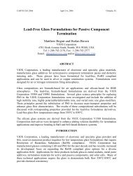
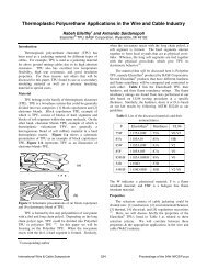
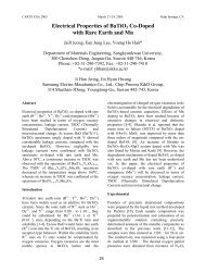
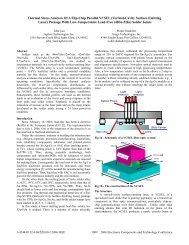
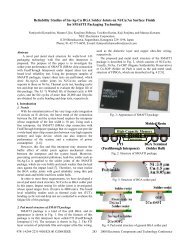
differentiate transient responses between a temperature cycledassembly and a reference one.III. Test VehicleThe test vehicle used in this study is PB18 flip chippackage without underfill, which is a daisy-chain flip chipwith 48 eutectic 63Sn37Pb solder bumps around theperipheral <strong>of</strong> the package. The die size is 6.35 mm × 6.35 mm× 0.6 mm and the typical bumps are 190 µm in diameter andspaced with a pitch <strong>of</strong> 457 µm, with twelve located on eachedge <strong>of</strong> the package. This test vehicle has 10 PB18 flip chipson each board numbered from chip 1 to chip 10, as shown inFigure 2(a). Figure 2(b) shows the schematic <strong>of</strong> flip chippackage with dimension. The laser excitation and detectionpattern for the test vehicle are shown in Figure 3 and the graycircles represent the solder bumps on the peripheral.<strong>Chip</strong>1 <strong>Chip</strong>2 <strong>Chip</strong>3 <strong>Chip</strong>4 <strong>Chip</strong>5<strong>Chip</strong>6 <strong>Chip</strong>7 <strong>Chip</strong>8 <strong>Chip</strong>9 <strong>Chip</strong>10(a)minute dwell time at the two temperature extremes separately.In phase I, four boards were thermal cycled up to 70 cycles.The boards were taken out after every ten cycles and FCPs oneach board were tested for presence <strong>of</strong> cracks by measuringelectronic resistance and taking laser ultrasound test. Thesemeasurements were repeated every 10 cycles and stoppedafter 70 cycles. After 70 cycles, FCPs on the boards werecross-sectioned to check for presence <strong>of</strong> cracks using amicroscope. The test results with resistance measurementshow that resistance values were essentially constant until 50cycles when the resistance values went to infinity. For laserultrasound measurements, MCC values began to increasegradually from 10 cycles until 50 cycles when there was asharp jump. Cross-section was done only after 70 cycles, andthe results show that all solder bumps at the corner hadthrough cracks, while solder bumps at the center had partialcracks.Phase II studies were refinements <strong>of</strong> phase I studies. Thisis because in phase II studies, seven boards were thermalcycled starting from 27 cycles to 56 cycles at the increment <strong>of</strong>approximate five cycles. After each five cycles, only oneboard was pulled out and tested to track crack initializationand propagation in solder bumps. Smaller thermal cycleincrements were used to help determine exactly when crackswere initiated. In this phase, resistance, laser ultrasound andscanning acoustic microscopy (SAM) measurements werecarried out for each board. In addition to these measurements,cross-sections <strong>of</strong> these FCPs were done to validate previousmeasurement results.140120100Thermal Cycling Pr<strong>of</strong>ile125 125 12512580(b)Figure 2. (a) Layout <strong>of</strong> test vehicle (b) Cross section <strong>of</strong>flip chip (not to scale, unit in microns)36…25Temperature ('C)604025200-20-40-600601560159030903120462046506150618076807710-40 -40-40Time (Seconds)9210924037…481Solder Bump &Detection PositionExcitation Laser Spot…Figure 3. Excitation and detection patternIV. Experimental ProceduresATC tests were performed in two phases on the FCP testvehicles following JEDEC standard JESD22-A104-B and theATC pr<strong>of</strong>ile is shown in Figure 4. The temperature pr<strong>of</strong>ile isfrom -40°C (minimum) to 125°C (maximum), with a 25-1224…13Figure 4. Pr<strong>of</strong>ile <strong>of</strong> ATC testV. Experimental Results and DiscussionsFigure 5(a) shows the transient time domain laserultrasound signals <strong>of</strong> PB18 FCPs, which went throughdifferent number <strong>of</strong> thermal cycles, in the interval <strong>of</strong> [0 20.48]µs. Figure 5(b) shows the corresponding power spectrums <strong>of</strong>time domain signals. It is observed that there is a largerdifference between time-domain signals and there are largerfrequency shifts backward with increasing number <strong>of</strong> thermalcycles. Figure 6(a) and (b) show this frequency shift aroundfrequency peaks <strong>of</strong> 100 KHz and 300 KHz locally. Thisdecreasing trend <strong>of</strong> frequency peaks indicates qualitydegradation <strong>of</strong> solder bumps through thermal cycling.613 2008 Electronic Components and Technology Conference
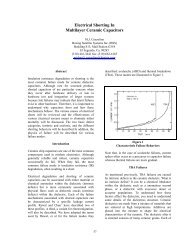
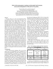
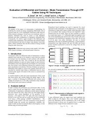
Mean Centered Voltage Signal (V)0.20.150.10.050-0.05-0.1-0.150 Cycle10 Cycles20 Cycles30 Cycles40 Cycles50 Cycles60 Cycles70 Cycles-0.20 5 10 15 20Time (micro seconds)Power Spectrum250200150100500 Cycles10 Cycles20 Cycles30 Cycles40 Cycles50 Cycles60 Cycles70 Cycles00 2 4 6 8 10(a)Frequency (Hz)x 10 5(b)Figure 5. (a) Time domain signals and (b) power spectrum<strong>of</strong> time domain signalsPower Spectrum250200150100Power Spectrum500 Cycles10 Cycles20 Cycles30 Cycles40 Cycles50 Cycles60 Cycles70 Cycles00.8 0.9 1 1.1 1.2 1.3 1.4 1.5 1.6Frequency (Hz)x 10 5454035302520151050 Cycles10 Cycles20 Cycles30 Cycles40 Cycles50 Cycles60 Cycles70 Cycles02 2.5 3 3.5 4 4.5 5(a)Frequency (Hz)x 10 5(b)Figure 6. Frequency shifts around frequency peaks: (a)100 KHz and (b) 300 KHzIn phase I study, resistance measurement <strong>of</strong> the daisychainedFCPs through thermal cycling is shown in Figure7(a). It is observed that the electronic resistance almostremained a constant value <strong>of</strong> 2.5 Ohms before 50 thermalcycles and there was a sharp jump from 2.5 Ohms to infinityaround 50 thermal cycles, indicating the appearance <strong>of</strong> athrough crack in solder bumps <strong>of</strong> FCPs. It is shown fromFigure 7(a) that resistance value is not a good indicator <strong>of</strong>quality degradation or crack propagation <strong>of</strong> solder bumpsthrough thermal cycling since it did not show changes withincreasing number <strong>of</strong> thermal cycles before through crackappeared. Comparably, the mean and maximum MCC valueswith thermal cycles are shown in Figure 7(b). The maximumMCC value was obtained from corner solder bump. There wasa steady increase for both mean and maximum MCC valuesbefore 50 cycles and it indicated quality degradation <strong>of</strong> solderbumps with increasing number <strong>of</strong> thermal cycles. There was asharp jump for MCC values at 50 cycles and it indicated asevere quality degradation <strong>of</strong> solder bumps (whichcorresponds to a through crack observed with cross-section <strong>of</strong>FCP). Therefore, the quality degradation <strong>of</strong> solder bump orcrack propagation was tracked using laser ultrasoundinterferometricinspection technique. The distribution <strong>of</strong> MCCvalues at all fourth-eight solder bumps with increasing <strong>of</strong>thermal cycles is shown in Figure 8. The largest MCC valuesalways lay at the corner bumps <strong>of</strong> FCPs and it showed cornerbumps were critical ones in ATC tests. It agreed with the FEsimulation and was validated by cross-sections <strong>of</strong> solderbumps. Cross section pictures <strong>of</strong> solder bumps #25 to 36 onone edge after 70 thermal cycles were shown in Figure 9.Through cracks were clearly observed for corner bumps orbumps close to the chip corner and all the cracks lay near theUBM layer. For the solder bumps lying in the center position<strong>of</strong> chip edge, the cracks propagated into the solder bumpsfrom bump corner, however through cracks did not form yetin these bumps after 70 thermal cycles.In phase II study, the MCC values with thermal cycles areshown in Figure 10 and it provided a refined study <strong>of</strong> solderbump quality degradation in the critical range. Similar tophase I results, MCC values increased with thermal cyclesfrom 27 to 56 cycles, indicating quality degradation <strong>of</strong> solderbumps with increasing number <strong>of</strong> thermal cycles in ATC tests.A sharp jump <strong>of</strong> MCC value was observed at 50 cycles, and itindicated a severe quality degradation <strong>of</strong> solder bumps (whichcorresponds to through crack observed with cross-section).The cross section pictures <strong>of</strong> critical solder bump #25 at thecorner and least-critical solder bump # 30 with thermal cyclesare shown in Figure 11(a) and (b) separately. It is clearlyshown that crack appeared in the critical solder bump #25around 32 thermal cycles, much earlier than solder bump #30.The cracks started from bump corners, near the UBM layerand propagated into the internal <strong>of</strong> solder bump withincreasing number <strong>of</strong> thermal cycles. Through crack wasobserved around 50 cycles for the critical solder bump #25.614 2008 Electronic Components and Technology Conference
5040Inf10.8MCC-MeanMCC-MaxResistance(Ohm)3020MCC Results0.60.4Sharp Jump102.5 2.5 2.5 2.6 2.7 2.700 10 20 30 40 50 60 70Number <strong>of</strong> Cycles(a)0.200 10 20 30 40 50 60 70Number <strong>of</strong> Cycles(b)Figure 7. (a) Resistance with thermal cycles (b) MCCvalues with thermal cycles from phase I study0 cycle1Max=0.01439Min=0.00183Mean=0.0081010 cycles1Max=0.03395Min=0.00885Mean=0.0187020 cycles1Max=0.05628Min=0.01229Mean=0.026910.50.50.50022020-2-2030 Cycles Max=0.0915940 Cycles1Min=0.02182Mean=0.044991Y (mm)X (mm)Y (mm)-2-20X (mm)2Max=0.19584Min=0.05162Mean=0.10164050 Cycles12Y (mm)0-2-202X (mm)Max=0.53696Min=0.14618Mean=0.271480.50.50.5020Y (mm)Y (mm)-2-220X (mm)X (mm)020Y (mm)-2-20X (mm)2020Y (mm)Y (mm)-2-20X (mm)X (mm)260 Cycles1Max=0.60896Min=0.19105Mean=0.3715470 Cycles1Max=0.82719Min=0.26211Mean=0.544780.50.5020Y (mm)-2-220X (mm)02Y (mm)0-2-202X (mm)Figure 8. MCC values <strong>of</strong> forty-eight solder bumps with thermal cyclesFigure 9. Cross sections <strong>of</strong> bumps #25-36 after 70 cycles615 2008 Electronic Components and Technology Conference
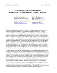
MCC Results0.70.60.50.40.30.20.1MCC-MeanMCC-MaxSharp Jump020 30 40 50 60Number <strong>of</strong> CyclesFigure 10. MCC values with thermal cycles from phaseII studyTherefore, the cross-section pictures validated laserultrasound inspection results and crack propagationextracted from cross-sections agreed well with inspectionresults. C-mode Scanning acoustic microscopy (CSAM)pictures were taken <strong>of</strong> FCPs in phase II at two adjacentscanning layers, as shown in Figure 12 using the SonixUHR-2001 SAM system with one 110-MHz ultrasonictransducer. The gray or darker circles in Figure 13represent solder bumps at the edges <strong>of</strong> FCPs. When thermalcycles increased, lighter areas (marked with red circles asshown in Figure 13) were observed in solder bumpsstarting from the corner bump and these lighter areasindicated appearance <strong>of</strong> cracks in solder bumps. However,it is still hard to see clearly the cracks in solder bumps fromCSAM images. At the same time, solder bumps were notquite clear themselves in CSAM images because <strong>of</strong> theedge effect <strong>of</strong> the CSAM technique since solder bumps layon the four edges <strong>of</strong> the FCPs.(a)(b)Figure 11. (a) Cross-sections <strong>of</strong> solder bump #25 with thermal cycles(b) Cross-sections <strong>of</strong> solder bump #30 with thermal cycles(a)(b)Figure 12. CSAM pictures <strong>of</strong> FCPs through different thermal cycles captured at two adjacent layers(a) layer 1 (b) layer 2616 2008 Electronic Components and Technology Conference
VI. Finite Element Modeling <strong>of</strong> Solder Bump Thermal<strong>Reliability</strong>In this paper, a three-dimensional (3-D) quarter FEmodel for nonunderfilled FCP was developed by usingANSYS 11.0 [18], with the dimensions taken to be averagevalues <strong>of</strong> measurements on several test vehicles (Figure2(b)). Three boundary conditions were applied to the 3Dquartermodel as shown in Figure 13, which was subjectedto a thermal cycling condition <strong>of</strong> -40°C to 125°C same asthe condition used in ATC test. The reference temperature<strong>of</strong> stress-free was taken to be ambient temperature 25°C.The material models and properties <strong>of</strong> FCP used in FEanalysis are summarized in Table 1. Two constitutive laws,elastic-plastic-creep and Anand viscoplastic, wereemployed to represent inelastic behavior <strong>of</strong> eutectic63Sn37Pb solder. The fatigue life <strong>of</strong> solder bump has beenfound to correlate with inelastic strain energy density W[14, 16], which is integral <strong>of</strong> the stress σijwith respect tointhe inelastic strain εij, and defined in Equation (2).Element volume averaging method (Equation (3)) [8, 10] isemployed to calculate the inelastic SED∆W avgaccumulated or dissipated per cycle from theinterface elements <strong>of</strong> critical solder bump, as shown inFigure 14. This method can minimize the effect <strong>of</strong> meshsensitivity and stress-strain singularity for corner elements[8, 10]. In viscoplastic model, the inelastic SEDaccumulated per cycle ∆Wavgis plastic SED∆W viscoplasticper cycle. In elastic-plastic-creep model,∆W avgis the sum <strong>of</strong> accumulated plastic SED∆W plasticper cycle and accumulated creep SED∆W creepper cycle. The simulated thermal cyclingcontinues until the change in element averaged inelasticSED per cycle ≤ 1% between two consecutive cycles.inεwhere, ∆ Wiinterface element i ,W∆ W =ijin= ∫ σ dε(2)avg0n∑i=1niji=1iij∆W⋅∆V∑∆Vii(3): inelastic SED accumulated in a cycle in∆ : volume <strong>of</strong> interface element iViBC: y=0ZXYBC: x=y=0BC: x=0DieUBMSolder bumpSolder maskFR4 SubstrateFigure 13. Three-dimensional quarter FE model andboundary conditionsLayer to averaging SED per cycleCritical solder bumpInner solder bumpSymmetryCorner solder bumpFigure 14. Meshing <strong>of</strong> solder bump and SED extractingby volumetric averagingSilicon DieAl/Cu/NiUBMCu PadSolder MaskFR4 Substrate63Sn37PbTable 1 Material models and properties for FE Model[8], [10]Constitutive ModelElastic isotropicElastic isotropicElastic isotropicTemp-dependentelastic, isotropicTemp-dependentelastic, orthotropicElastic-plastic-creepor ViscoplasticE (N/mm^2)131000700001200004700@298K,3914@323K,2342@373K,1556@398Kin plane:27924-37Tout <strong>of</strong> plane:12204-16T30000@278K,27143@323KCTE (ppm/K)Poisson Ratio2.623.11760in plane:16.0out <strong>of</strong> plane:84.024.50.280.350.350.47in plane:0.11out <strong>of</strong> plane:0.390.35A. Viscoplastic Constitutive Model <strong>of</strong> SolderThe Anand viscoplastic model is available in ANSYSlibrary and VISCO107 element is used as the large strainelement in FE model to represent viscoplastic/creep617 2008 Electronic Components and Technology Conference
ehavior <strong>of</strong> the solder [18]. The substrate, silicon die,UBM, copper pad and solder mask, which exhibit elasticbehavior, are modeled by using SOLID185 elements. InAnand model, a deformation resistance variable “s” is usedto represent averaged isotropic resistance to inelastic flow<strong>of</strong> the materials [18]. One flow and three evolutionequations to express Anand model are given in Equations(4-7). The Anand model constants proposed by Shi et al.[7] and Yeo et al. [8] were used in this study, as shown inTable 2.Flow equation:dsB dεαp= { h0(| B|) } ⋅dt | B | dt(4)Evolution equations:dεp σ 1/ m Q= A[sinh( ξ )] exp( − )dt s κT(5)sB = 1− *s(6)Λ dε/* pdt Q ns = s⋅ [ exp( )]A κT(7)Table 2 Anand model constants for 63Sn37Pb solder [8,18]Parameter Parameter/Unit DescriptionC1 S0(N/mm^2) Initial value <strong>of</strong> deformationresistanceC2 Q/k(1/K) Activationenergy/Boltzmann’sconstantC3 A(1/sec) Pre-exponential factorC4 ξ Multiplier <strong>of</strong> stressC5 m Strain rate sensitivity <strong>of</strong>stressC6 H0(N/mm^2) Hardening constantC7S Λ Coefficient for deformation(N/mm^2) resistance saturation valueC8 N Deformation resistancevalueC9 a Strain rate sensitivity <strong>of</strong>hardeningB. Elastic-Plastic-Creep Constitutive Model <strong>of</strong> SolderThe elastic-plastic-creep model is divided into a timeindependentplasticity model and a time-dependent creepmodel and SOLID185 element is used to represent inelasticbehavior <strong>of</strong> the solder in ANSYS [18]. The timeindependentplastic description is described by multi-linearisotropic hardening rule (MISO) characterized by sixparameters ( ε1, ε2, ε3, σ1, σ2,σ3), as shown in Table 3and Figure 15.Figure 15.Time-independent plasticity model [10]Table 3 Time-independent plastic material model forSn63Pb37 Solder [10]Temperature(K)ε1ε2ε3σ1σ2(MPa)σ3(MPa)(MPa)278 7.00e-4 3.00e-3 1.00e0 21 41 600323 7.00e-4 3.00e-3 1.00e0 19 31 400The time-dependent plasticity or creep model <strong>of</strong> solderis realized in ANSYS using an implicit time integrationmodel (TBOPT = 8) [18]. The steady-state creep behavior<strong>of</strong> 63Sn37Pb solder is described by strain rate hyperbolicsine formation, as shown in Equation (8). The equationcoefficients for eutectic Sn63Pb37 are given in Table 4.−C4 / T& (8)εcreep= C1[sinh( C2σ)]C3eTable 4 Creep equation coefficients for Sn63Pb37Solder [10]C1(1/sec) C2(1/MPa) C3C4(K)10 0.2 2 5401.2C. FE Simulation ResultsTwo consecutive thermal cycles were simulated toachieve the change in accumulated inelastic SED∆W avg≤ 1% between two consecutive cycles both forviscoplastic and elastic-plastic-creep models. Figure 16(a)shows plastic strain contours <strong>of</strong> six solder bumps in a rowfrom corner to inner solder bump from viscoplastic model.It is observed that the plastic strain decreases consecutivelyfrom the corner solder bump to the inner bump, numberedfrom bump #1 to bump #6, respectively. The corner solderbump is the critical one with maximum plastic strain.Figure 16(b) shows the plastic strain contour <strong>of</strong> criticalsolder bump. Figure 17(a) shows plastic SED contours <strong>of</strong>six solder bumps from corner to inner solder bump fromviscoplastic model. It is observed that the plastic SEDdecreases consecutively from the corner solder bump to theinner bump. The corner solder bump is the critical one withmaximum plastic SED, which was observed to showappearance <strong>of</strong> crack and fail first by cross-sections asshown in Figures 9 and 11. Figure 17(b) shows the plasticSED contour <strong>of</strong> critical solder bump, in which the criticalarea with maximum plastic SED value is clearly observed618 2008 Electronic Components and Technology Conference
to lie at the elements interfacing with the BLM layer.Figures 18(a) and (b) show plastic strain and creep straincontours <strong>of</strong> critical solder bump from elastic-plastic-creepmodel respectively. The plastic SED and creep SEDcontours <strong>of</strong> critical solder bump from elastic-plastic-creepmodel are shown in Figures 19(a) and (b) respectively. Allthese simulation results have a good agreement with crosssectionobservations <strong>of</strong> solder bump cracks. It took longertime for FE simulation based on elastic-plastic-creep modelto converge than that based on viscoplastic model,therefore the following analysis is based on viscoplasticmodel.(b)Figure 17. (a) Plastic SED <strong>of</strong> solder bumps fromviscoplastic model (b) Plastic SED <strong>of</strong> critical solderbump from viscoplastic model(a)(a)(b)Figure 16. (a) Plastic strain contour <strong>of</strong> solder bumps fromviscoplastic model(b) Plastic strain contour <strong>of</strong> criticalsolder bump from viscoplastic model(b)Figure 18. (a) Plastic strain contour <strong>of</strong> critical bumpfrom elastic-plastic-creep model(b) Creep strain contour <strong>of</strong> critical bump from elasticplastic-creepmodel(a)619 2008 Electronic Components and Technology Conference
has a viscoplastic SED accumulated per cycleapproximately 1.5 times higher than the inner solder bump.In laser ultrasound testing, the corner solder bump has anormalized MCC value approximately 1.6 times higherthan the inner solder bump. The correlation between∆W avgfrom viscoplastic model and normalized MCCvalues is plotted in Figure 20. The R-Squared value <strong>of</strong>0.9549 shows a strong linear correlation between them, asshown in Figure 20.(a)Table 5 Averaged plastic strain energy densitiesand normalized laser ultrasound testing valuesfor six bumps from corner to inner bumpBumpGroup #∆ W avg(MPa) Normalized MCC Value1 17.093 1.00E+002 15.369 8.77E-013 14.002 8.43E-014 12.945 6.69E-015 12.217 6.36E-016 11.812 6.27E-01(b)Figure 19. (a) Plastic SED <strong>of</strong> critical bump from elasticplastic-creepmodel (b) Creep SED <strong>of</strong> critical solder bumpfrom elastic-plastic-creep modelThe plastic SED∆Wavgaccumulated per cycle isselected as the failure parameter to predict solder bumpfatigue life in FE analysis since it is correlated with thethermal fatigue <strong>of</strong> solder bump. The laser ultrasound resultsmeasured directly on top <strong>of</strong> each solder bump tracked thequality degradation <strong>of</strong> solder bump through ATCs;therefore the testing results are also correlated with thermalfatigue <strong>of</strong> solder bump. The MCC value at 50 thermalcycles, which corresponds to critical number <strong>of</strong> cycleswhen through crack appeared, is selected as experimentalfailure parameter. In terms <strong>of</strong> structural symmetry <strong>of</strong> FCPused in this study and in order to minimize variation inmeasurements, forty-eight solder bumps were grouped intosix groups in calculating experimental failure parameters.The eight solder bumps (bumps #1, 12, 13, 24, 25, 36, 37and 48 as shown in Figure 3) with the same locationcharacteristics in FCP as solder bump #1 were grouped intogroup #1. The eight solder bumps with the same locationcharacteristics as solder bumps #2 to #6 were grouped intogroup #2 to #6 respectively by analogy. The sum <strong>of</strong> eightMCC values from eight solder bumps in each group wascalculated and six sums were obtained from these sixgroups. The plastic SED ∆Wavgaccumulated per cycle <strong>of</strong>solder bumps #1 to #6 from viscoplastic model andcorresponding normalized MCC values at 50 cycles arelisted in Table 5. In FE analysis, the corner solder bumpNormalized Testing Value1.00E+008.00E-016.00E-014.00E-012.00E-010.00E+00y = 0.0742x - 0.2567R 2 = 0.95490 5 10 15 20Plastic SED Dissipation per Cycle (MPa)Figure 20. Correlation between ∆ W fromviscoplastic model and MCC values from laser ultrasoundtestingD. Solder Fatigue Life Predictions:Two prediction models were selected from the literatureto predict solder bump fatigue life. Solomon’s method [11]is strain-based approach and Zahn’s method [10] is energybasedapproach. Solomon’s strain-based approach is usedhere as a cross-examination <strong>of</strong> energy-based approach topredict fatigue life <strong>of</strong> flip chip solder bumps under cyclicthermal loading. The governing equations and coefficientsare listed in Table 6 for these two methods.avg620 2008 Electronic Components and Technology Conference
[13] Yan Wei, et al., “Double Bump <strong>Flip</strong>-<strong>Chip</strong> Assembly”,<strong>IEEE</strong> Transactions on Packaging Manufacturing, Vol.29, No. 2, 2006.[14] Qi Yan, Ghorbani H. R., and Spelt J. K., “ThermalFatigue <strong>of</strong> SnPb and SAC Resistor Joints: Analysis <strong>of</strong>Stress-Strain as a Function <strong>of</strong> Cycle Parameters”, <strong>IEEE</strong>Transactions on Advanced Packaging, Vol. 29, No. 4,November 2006.[15] Darveaux R., “Effect <strong>of</strong> Simulation Methodology onSolder Joint Crack Growth Correlation and Fatigue LifePrediction”, ASME Journal <strong>of</strong> Electronic Packaging,vol. 124, pp. 147-153, Sep. 2002.[16] Guven I., Kradinov V., and Madenci E., “StrainEnergy Density Criterion for <strong>Reliability</strong> Life Prediction<strong>of</strong> Solder Joints in Electronic Packaging”, ASMEJournal <strong>of</strong> Electronic Packaging, vol. 126, pp. 398-405,Sep. 2004.[17] Vandervelde B., Beyne E., et al., “ParameterizedModeling <strong>of</strong> <strong>Thermomechanical</strong> <strong>Reliability</strong> for CSPAssemblies”, ASME Transactions <strong>of</strong> ElectronicPackaging, vol. 125, page 498-505, 2003.[18] Wiese S., Jakschik S., Feustel F., and Meusel E.,“Fracture Behavior <strong>of</strong> <strong>Flip</strong> <strong>Chip</strong> Solder Joints”, 51stElectronic Components and Technology Conference,2001.[19] ANSYS Release 11.0-Theory Reference, ANSYS,Inc., 2007[20] Spera D. A., Thermal Fatigue and Materials andComponents, ASTM Special Technology Publication,1975, vol. 612.[21] Lau J. H., and Pao Y. H., Solder Joint <strong>Reliability</strong> <strong>of</strong>BGA, CSP, <strong>Flip</strong> <strong>Chip</strong> and Fine Pitch SMT Assemblies,New York, McGraw-Hall, 1997.[22] Pang H. L., Chong Y. R., and Sitaraman S. K., “FEAModeling <strong>of</strong> FCOB Assembly Warpage and StressedDue to Underfill Encapsulation and Thermal CyclingLoading”, in Proc. ASME Advanced Packaging, pp.803-807, June 1999.622 2008 Electronic Components and Technology Conference