VULASTIK L - vulkan group
VULASTIK L - vulkan group
VULASTIK L - vulkan group

You also want an ePaper? Increase the reach of your titles
YUMPU automatically turns print PDFs into web optimized ePapers that Google loves.
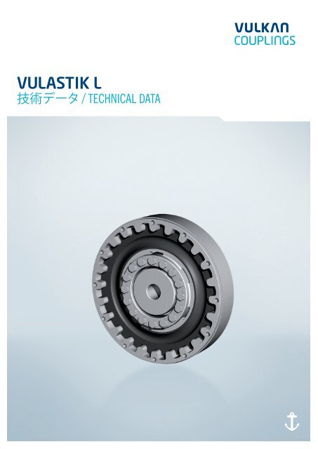
<strong>VULASTIK</strong> L技 術 データ / TECHNICAL DATA
有 効 性 約 款VALIDITY CLAUSE現 行 のカタログ は 旧 版 全 てに 代 わるものであり、 旧 版 刊 行 物 は 有 効 性が 失 効 しています。 製 品 の 新 開 発 ・ 改 善 に 伴 い、VULKAN はこのカタログに 含 まれる 内 容 を 修 正 し、 変 更 する 権 利 を 有 します。 新 しいデータは、 係る 修 正 または 変 更 の 後 に 注 文 されたカップリングに 関 してのみに 適 用されます。 最 新 のカタログを 使 用 してご 確 認 いただくのは、ユーザーの責 任 とみなされます。 各 製 品 の 最 新 カタログは VULKAN のウェブサイト( www.<strong>vulkan</strong>.com) からご 入 手 いただけます。The present catalogue shall replace all previous editions, any previous printingsshall no longer be valid. Based on new developments, VULKAN reserves the rightto amend and change any details contained in this catalogue respectively. The newdata shall only apply with respect to couplings that were ordered after said amendmentor change. It shall be the responsibility of the user to ensure that only thelatest catalogue issue will be used. The respective latest issue can be seen on thewebsite of VULKAN on www.<strong>vulkan</strong>.com.このカタログに 記 載 された 情 報 は、VULKAN が 現 在 使 用 している、 説 明で 指 定 された 条 件 に 従 った 技 術 標 準 を 参 照 します。 動 力 伝 達 装 置 によるシステム 動 作 への 影 響 は 一 切 、システムアドミニストレーターの 責 任と 決 定 になります。The data contained in this catalogue refer to the technical standard as presentlyused by VULKAN with defined conditions according to the explanations. It shall bethe sole responsibility and decision of the system administrator for the drive line todraw conclusions about the system behaviour.VULKAN ねじり 振 動 解 析 は 通 常 、 純 粋 な 機 械 的 質 量 - 弾 性 システムのみに 適 用 します。 部 品 専 門 メーカーである VULKAN は、ねじり 振 動 システムの 解 析 ( 静 止 、 一 過 性 )にシステムの 責 任 を 負 うものではありません。解 析 の 正 確 度 は 使 用 するデータと VULKAN に 提 供 される 対 応 するデータの 厳 密 性 によって 異 なります。VULKAN torsional vibration analysis usually only consider the pure mechanicalmass-elastic system. Being a component manufacturer exclusively, VULKANassumes no system responsibility with the analysis of the torsional vibration system(stationary, transiently)! The accuracy of the analysis depends on the exactness ofthe used data and the data VULKAN is provided with, respectively.当 社 は、 技 術 的 な 進 歩 により 変 更 する 権 利 を 留 保 します。ご 質 問 やお 問い 合 わせは、VULKAN までご 連 絡 ください。Any changes due to the technological progress are reserved. For questions orqueries please contact VULKAN.日 付 : 01/2012複 製 、 再 印 刷 、 翻 訳 の 権 利 はすべて 当 社 が 留 保 します。当 社 は、 寸 法 および 構 造 を 予 告 なく 変 更 する 権 利 を 留 保 します。Status: 01/2012All duplication, reprinting and translation rights are reserved.We reserve the right to modify dimensions and constructions without prior notice.02 <strong>VULASTIK</strong> L
目 次CONTENTS020304060910有 効 性 約 款VALIDITY CLAUSE目 次CONTENTS特 性 と 説 明CHARACTERISTICS AND DESCRIPTION技 術 データの 表LIST OF TECHNICAL DATAシリーズの 要 約SUMMARY OF SERIES寸 法 / 質 量 - 慣 性 のモーメント/ 質 量DIMENSIONS/MASS-MOMENTS OF INERTIA/MASSES10 <strong>VULASTIK</strong> L シリーズ 2800 / Series 280011 <strong>VULASTIK</strong> L シリーズ 2801 / Series 280112 <strong>VULASTIK</strong> L シリーズ 2802 / Series 280213 <strong>VULASTIK</strong> L シリーズ 2803 / Series 280314 <strong>VULASTIK</strong> L シリーズ 2810 / Series 281016 <strong>VULASTIK</strong> L シリーズ 2811 / Series 281117 <strong>VULASTIK</strong> L シリーズ 2830 / Series 2830<strong>VULASTIK</strong> L03
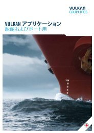
特 性 と 説 明CHARACTERISTICS AND DESCRIPTIONVULKARDAN G カップリング / <strong>VULASTIK</strong> L Couplingsトルク 範 囲 : 0.40 – 40.00 kNm / Torque range: 0.40 – 40.00 kNm04 <strong>VULASTIK</strong> L
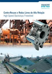
高 柔 軟 性 <strong>VULASTIK</strong> L カップリング<strong>VULASTIK</strong> L カップリングは、T KN = 0.40 kNm から 40.0 kNm のトルク 範 囲でご 提 供 いたします。 高 柔 軟 性 <strong>VULASTIK</strong> L カップリングは、 接 続 された機 械 の 半 径 方 向 、 軸 方 向 および 角 度 方 向 シャフト 変 位 量 を 補 正 するねじりに 柔 軟 なカップリングです。さまざまなシステム 要 件 に 合 わせたカップリングの 調 整 が 行 なえるように4 つのゴムと 品 質 タイプとシリコンタイプをご 提 供 しています。<strong>VULASTIK</strong> L カップリングは、 標 準 デザインあるいは 2 つの 並 列 エレメントを 使 用 したデュアルデザインの 種 類 があります。記 載 のデータは 最 大 値 を 示 しますが、すべて 同 時 にこれらの 最 大 値 が 得られるとは 限 りません。 操 作 状 況 により、 相 互 作 用 が 働 き、これらの 値 が得 られないことがあります。カップリングの 選 択 にはこのことをご 配 慮 ください。<strong>VULASTIK</strong> L カップリングの 主 な 構 成 部 品 は、ハブとフランジケース、そしてこれらの 間 に 配 置 されたディスク 形 状 のエレメントです。ディスクエレメントは 内 径 に 加 硫 することによって 接 続 され、 外 径 は 歯 部 に「プラグイン」することによってフランジケースに 接 続 されます。 歯 部 は 軸 方 向 の「プラグイン」(ブラインドアセンブリ) 機 能 とシャフト 変 位 の 補 正 を 提 供 します。 許 容 可 能 なカップリングの 変 位 量 は 0.5°です。<strong>VULASTIK</strong> L のエレメントは、 熱 耐 性 のあるゴム 製 で、 許 容 周 囲 温 度 は-45°C から +90°C の 範 囲 になっています。 温 度 に 敏 感 なアプリケーションには、シリコン 製 エレメントをご 使 用 いただけます ( 周 囲 温 度 : -45°C から +120°C )。 寿 命 を 長 く 保 つには、 断 面 積 が 十 分 に 大 きい 通 気 口 を 装 備する 配 慮 が 必 要 です。これは、ベルハウスマウントの 取 付 けに 非 常 に 重要 です。Highly Flexible <strong>VULASTIK</strong> L Couplings<strong>VULASTIK</strong> L couplings are available in the torque range T KN = 0.40 kNm to 40.0kNm. The <strong>VULASTIK</strong> L coupling is a torsionally flexible coupling that compensatesaxial, angular and, to a certain degree, radial displacements of the connectedmachinery. Four rubber qualities and silicone are available in order to tune thecoupling to the various system requirements.<strong>VULASTIK</strong> L couplings are available with one elastic element in standard design orin Dual design with two parallel elements.The given data represent maximum values which may not arise at the same time.The mutual influence of operating conditions leads to a reduction of these valuesand must be considered during the coupling selection.The main parts of the <strong>VULASTIK</strong> L coupling are hub and flanged casing, betweenthese, the disc-shaped element is arranged. This disc element is connected byvulcanization at its inner radius, the outer radius is connected to the flanged casingby a „plug-in“ toothing. This toothing provides the axial „plug-in“ (blind assembly)feature and compensation of shaft displacements. The permissible angular couplingdisplacement is 0.5°.The <strong>VULASTIK</strong> L elements are available in heat-resistant rubber with the admissibleambient temperature range from -45°C to +90°C. For temperature-critical applicationselements in silicone are available (ambient temperature range from -45°C to +120°C).With respect to a long lifetime, consideration should be given to sufficiently large ventilationcross sections. This is very important when considering bell-house mountings.高 柔 軟 性 <strong>VULASTIK</strong> L カップリングの 断 面 図デュアルデザインでエレメント 1 つ 付 きSectional view of a highly flexible <strong>VULASTIK</strong> L couplingwith one element and in Dual design<strong>VULASTIK</strong> L05
技 術 データの 表LIST OF TECHNICAL DATAサイズ寸 法グループ定 格 トルク許 容 最 大トルク 1許 容 最 大トルク 2許 容 最 大トルク 範 囲許 容 変 動トルク許 容パワーロス許 容 回 転速 度許 容 半 径方 向 変 位半 径 方 向剛 さ動 的 ねじり剛 さ相 対 減 衰SizeDimensionGroupNorminalTorqueMax.Torque 1Max.Torque 2Max.Torque RangePerm. VibratoryTorquePerm.Power LossPerm. RotationalSpeedPerm. RadialCouplingDisplacementRadialStiffnessDynamicTorsionalStiffnessRelativeDampingT KNkNmT Kmax1kNmT Kmax2kNm∆T maxkNmT KWkNmP KV50, 1hkWn Kmax1/min∆K rmmC rdynkN/mmC Tdyn1)kNm/radψ 2)14110.40 0.600.65 0.160.60 2.00 1.001412 0.50 0.75 0.80 0.20 0.80 2.50 1.1314101.800.209 5300 1.01413 0.50 0.75 1.11 0.20 1.40 5.00 1.131418 0.50 0.75 1.37 0.20 3.60 12.00 1.1316110.63 0.951.05 0.250.65 2.50 1.001612 0.80 1.20 1.29 0.32 1.25 4.50 1.1316102.800.361 4100 1.01613 0.80 1.20 1.80 0.32 1.70 8.50 1.131618 0.80 1.20 2.17 0.32 5.20 20.00 1.1319111.00 1.501.61 0.401.00 4.50 1.001912 1.25 1.88 1.98 0.50 1.90 7.50 1.1319104.500.328 3600 1.01913 1.25 1.88 2.76 0.50 2.30 14.00 1.131918 1.25 1.88 3.45 0.50 6.70 30.00 1.1322111.60 2.402.67 0.641.5 1.20 7.00 1.002212 2.00 3.00 3.28 0.80 1.0 2.30 12.00 1.132213 2.00 3.00 4.57 0.80 1.0 2.80 21.00 1.1322107.200.413 32002216 2.00 3.00 4.57 0.80 1.0 6.30 36.00 1.132218 2.00 3.00 5.44 0.80 1.0 8.60 50.00 1.13221A 2.00 3.00 5.44 0.80 1.0 12.40 72.00 1.1322D13.20 4.805.34 1.281.5 2.40 14.00 1.0022D2 4.00 6.00 6.56 1.60 1.0 4.60 24.00 1.1322D3 4.00 6.00 9.14 1.60 1.0 5.60 42.00 1.1322D014.400.826 320022D6 4.00 6.00 9.14 1.60 1.0 12.60 71.00 1.1322D8 4.00 6.00 10.88 1.60 1.0 17.20 100.00 1.1322DA 4.00 6.00 10.88 1.60 1.0 24.80 144.00 1.1326112.50 3.754.10 1.001.5 1.50 11.50 1.002612 3.15 4.72 5.04 1.25 1.0 2.90 19.50 1.132613 3.15 4.72 7.02 1.25 1.0 3.50 36.00 1.13261011.250.609 27002616 3.15 4.72 7.02 1.25 1.0 7.70 58.00 1.132618 3.15 4.72 8.55 1.25 1.0 10.50 80.00 1.13261A 3.15 4.72 8.55 1.25 1.0 15.10 116.00 1.1326D15.00 7.508.20 2.001.5 3.00 23.00 1.0026D2 6.30 9.50 10.08 2.50 1.0 5.80 39.00 1.1326D3 6.30 9.50 14.04 2.50 1.0 7.00 72.00 1.1326D022.501.218 270026D6 6.30 9.50 14.04 2.50 1.0 15.40 116.00 1.1326D8 6.30 9.50 17.10 2.50 1.0 21.00 160.00 1.1326DA 6.30 9.50 17.10 2.50 1.0 30.20 232.00 1.13技 術 データの 説 明 を 参 照 してください。1) VULKAN は、ねじり 振 動 の 取 付 けを 計 算 する 際 に、さらに C Tdyn warm (0.7)、C Tdyn la (1.35) and ψ warm (0.7) をご 使 用 いただくことを 推 奨 します。弾 性 エレメントの 物 理 的 特 性 により、C Tdyn のデータに 対 し、1/2 およびシリコンエレメントは、+10 % から -20 %、3、6、8 および Aのエレメントは、+20 % から -10 % の 公 差 が 可 能 です。2) 弾 性 エレメントの 物 理 的 特 性 により、ψ に 付 与 されたデータに 対 し、 以 下 の 公 差が 可 能 です。+15 % から -15 %(1, 2, 3 およびシリコン 製 エレメント)。+30 % から -15 %(6 のエレメント) および0 % から +45 %(8/A のエレメント)。See Explanation of the Technical Data.1) VULKAN recommend that the values C Tdyn warm (0.7), C Tdyn la (1.35) and ψ warm (0.7) beadditionally used when the installations of torsional vibrations are calculated.The properties of the rubber material mean that tolerances of +10 % to -20% for the 1/2 andsilicone elements and of +20 % to -10 % for the 3, 6, 8 and A elements with respect to the datagiven for C Tdyn are possible.2) Because of the physical properties of the elastic elements, the following tolerances with respectto the data given for ψ are possible:+15 % to -15 % for the 1, 2, 3 and silicone elements,+30 % to -15 % for the 6 elements and0 % to +45 % for the 8/A elements.06 <strong>VULASTIK</strong> L LTD (V. 1) 01/2012
サイズ寸 法グループ定 格 トルク許 容 最 大トルク 1許 容 最 大トルク 2許 容 最 大トルク 範 囲許 容 変 動トルク許 容パワーロス許 容 回 転速 度許 容 半 径方 向 変 位半 径 方 向剛 さ動 的 ねじり剛 さ相 対 減 衰SizeDimensionGroupNorminalTorqueMax.Torque 1Max.Torque 2Max.Torque RangePerm. VibratoryTorquePerm.Power LossPerm. RotationalSpeedPerm. RadialCouplingDisplacementRadialStiffnessDynamicTorsionalStiffnessRelativeDampingT KNkNmT Kmax1kNmT Kmax2kNm∆T maxkNmT KWkNmP KV50. 1hkWn Kmax1/min∆K rmmC rdynkN/mmC Tdyn1)kNm/radψ 2)30114.00 6.006.53 1.601.5 2.00 19.00 1.003012 5.00 7.50 8.03 2.00 1.0 3.80 30.00 1.133013 5.00 7.50 11.19 2.00 1.0 4.20 58.00 1.13301018.000.371 25003016 5.00 7.50 11.19 2.00 1.0 9.70 92.00 1.133018 5.00 7.50 12.69 2.00 1.0 13.20 125.00 1.13301A 5.00 7.50 12.69 2.00 1.0 19.00 181.30 1.1330D18.00 12.0013.06 3.201.5 4.00 38.00 1.0030D2 10.00 15.00 16.06 4.00 1.0 7.60 60.00 1.1330D3 10.00 15.00 22.38 4.00 1.0 8.40 116.00 1.1330D036.000.742 250030D6 10.00 15.00 22.38 4.00 1.0 19.40 183.00 1.1330D8 10.00 15.00 25.38 4.00 1.0 26.40 250.00 1.1330DA 10.00 15.00 25.38 4.00 1.0 38.00 362.60 1.1334116.30 9.4511.41 2.501.5 2.70 43.00 1.003412 8.00 12.00 14.04 3.20 1.0 4.10 67.00 1.133413 8.00 12.00 19.55 3.20 1.0 4.50 85.00 1.13341028.400.367 25003416 8.00 12.00 19.55 3.20 1.0 9.20 143.00 1.133418 8.00 12.00 21.45 3.20 1.0 12.60 200.00 1.13341A 8.00 12.00 21.45 3.20 1.0 18.10 303.00 1.1334D112.50 18.8022.82 5.001.5 5.40 85.00 1.0034D2 16.00 24.00 28.08 6.40 1.0 8.20 134.00 1.1334D3 16.00 24.00 39.10 6.40 1.0 9.00 170.00 1.1334D056.250.734 250034D6 16.00 24.00 39.10 6.40 1.0 18.40 285.00 1.1334D8 16.00 24.00 42.90 6.40 1.0 25.20 400.00 1.1334DA 16.00 24.00 42.90 6.40 1.0 36.20 605.00 1.1337118.00 12.0015.01 3.201.5 4.10 61.00 1.003712 10.00 15.00 15.01 4.00 1.0 6.30 94.00 1.133713 10.00 15.00 15.01 4.00 1.0 8.10 120.00 1.13371036.000.440 25003716 10.00 15.00 15.01 4.00 1.0 13.40 200.00 1.133718 10.00 15.00 15.01 4.00 1.0 18.70 279.00 1.13371A 10.00 15.00 15.01 4.00 1.0 27.80 413.00 1.13401110.00 15.0017.60 4.001.5 3.20 68.00 1.004012 12.50 18.80 21.65 5.00 1.0 4.70 105.00 1.134013 12.50 18.80 30.17 5.00 1.0 5.20 135.00 1.13401045.000.448 25004016 12.50 18.80 30.17 5.00 1.0 10.70 223.00 1.134018 12.50 18.80 37.50 5.00 1.0 14.60 310.00 1.13401A 12.50 18.80 37.50 5.00 1.0 21.00 450.00 1.13技 術 データの 説 明 を 参 照 してください。1) VULKAN は、ねじり 振 動 の 取 付 けを 計 算 する 際 に、さらに C Tdyn warm (0.7)、C Tdyn la (1.35) and ψ warm (0.7) をご 使 用 いただくことを 推 奨 します。弾 性 エレメントの 物 理 的 特 性 により、C Tdyn のデータに 対 し、1/2 およびシリコンエレメントは、+10 % から -20 %、3、6、8 および Aのエレメントは、+20 % から -10 % の 公 差 が 可 能 です。2) 弾 性 エレメントの 物 理 的 特 性 により、ψ に 付 与 されたデータに 対 し、 以 下 の 公 差が 可 能 です。+15 % から -15 %(1, 2, 3 およびシリコン 製 エレメント)。+30 % から -15 %(6 のエレメント) および0 % から +45 %(8/A のエレメント)。See Explanation of the Technical Data.1) VULKAN recommend that the values C Tdyn warm (0.7), C Tdyn la (1.35) and ψ warm (0.7) beadditionally used when the installations of torsional vibrations are calculated.The properties of the rubber material mean that tolerances of +10 % to -20% for the 1/2and silicone elements and of +20 % to -10 % for the 3, 6, 8 and A elements with respect tothe data given for C Tdyn are possible.2) Because of the physical properties of the elastic elements, the following tolerances withrespect to the data given for ψ are possible:+15 % to -15 % for the 1, 2, 3 and silicone elements,+30 % to -15 % for the 6 elements and0 % to +45 % for the 8/A elements.LTD (V. 1) 01/2012<strong>VULASTIK</strong> L07
技 術 データの 表LIST OF TECHNICAL DATAサイズ寸 法グループ定 格 トルク許 容 最 大トルク 1許 容 最 大トルク 2許 容 最 大トルク 範 囲許 容 変 動トルク許 容パワーロス許 容 回 転速 度許 容 半 径方 向 変 位半 径 方 向剛 さ動 的 ねじり剛 さ相 対 減 衰SizeDimensionGroupNorminalTorqueMax.Torque 1Max.Torque 2Max.Torque RangePerm. VibratoryTorquePerm.Power LossPerm. RotationalSpeedPerm. RadialCouplingDisplacementRadialStiffnessDynamicTorsionalStiffnessRelativeDampingT KNkNmT Kmax1kNmT Kmax2kNm∆T maxkNmT KWkNmP KV50, 1hkWn Kmax1/min∆K rmmC rdynkN/mmC Tdyn1)kNm/radψ 2)40D120.00 30.0035.20 8.001.5 6.40 136.00 1.0040D2 25.00 37.50 43.30 10.00 1.0 9.40 210.00 1.1340D3 25.00 37.50 60.34 10.00 1.0 10.40 270.00 1.1340D090.000.896 250040D6 25.00 37.50 60.34 10.00 1.0 21.40 445.00 1.1340D8 25.00 37.50 75.00 10.00 1.0 29.20 620.00 1.1340DA 25.00 37.50 75.00 10.00 1.0 42.00 900.00 1.13431116.00 18.7529.95 6.401.5 5.40 130.00 1.004312 20.00 30.00 36.84 8.00 1.0 7.90 190.00 1.134313 4310 20.00 30.00 72.00 51.33 8.00 0.600 2500 1.0 12.90 335.00 1.134316 20.00 30.00 54.29 8.00 1.0 24.80 528.00 1.134318 20.00 30.00 54.29 8.00 1.0 33.90 720.00 1.1343D132.00 37.5059.90 12.801.5 10.80 260.00 1.0043D2 40.00 60.00 73.68 16.00 1.0 15.80 380.00 1.1343D3 43D0 40.00 60.00 144.00 102.66 16.00 1.200 2500 1.0 25.80 670.00 1.1343D6 40.00 60.00 108.58 16.00 1.0 49.60 1055.00 1.1343D8 40.00 60.00 108.58 16.00 1.0 67.80 1440.00 1.13サイズ寸 法グループ定 格トルク許 容最 大トルク 1許 容最 大トルク 2許 容最 大トルク範 囲許 容変 動トルク許 容パワーロス許 容 回転 速 度許 容 半 径方 向 変 位半 径 方向 剛 さ動 的 ねじり 剛 さ相 対減 衰SizeDimensionGroupNorminalTorqueMax.Torque 1Max.Torque 2Max.TorqueRangePerm.VibratoryTorquePerm.Power LossPerm.RotationalSpeedPerm. RadialCouplingDisplacementRadialStiffnessDynamic Torsional StiffnessRelativeDampingT KNkNmT Kmax1kNmT Kmax2kNm∆T maxkNmT KWkNmP KV50.1hkWn Kmax1/min∆ K rmmC rdynkN/mm10% T KN 25% T KN 50% T KN 75% T KN 100% T KN ψ 2)C Tdyn1)kNm/rad1611 S 1610 0.80 1.20 1.60 1.01 0.25 0.500 4100 1.0 0.65 1.80 1.80 2.10 2.90 5.00 1.131911 S 1910 1.25 1.90 2.50 1.56 0.40 0.583 3600 1.0 1.00 2.70 2.70 3.20 4.60 7.80 1.132211 S 2210 2.00 3.00 4.00 2.57 0.64 0.733 3200 1.5 1.20 4.40 4.40 5.10 7.30 12.40 1.132611 S 2610 3.15 4.70 6.25 3.95 1.00 0.792 2700 1.5 1.50 6.90 6.90 8.10 11.50 19.50 1.133011 S 3010 5.00 7.50 10.00 6.29 1.60 0.633 2500 1.5 2.00 11.00 11.00 13.40 23.20 42.00 1.133111 S 3110 7.50 11.25 15.00 15.50 2.40 0.750 2500 1.5 3.70 23.00 23.00 27.30 43.20 79.80 1.133211 S 3210 6.30 9.45 12.60 8.33 2.00 0.708 2500 1.5 2.20 13.30 13.30 15.80 25.00 46.20 1.133411 S 3410 8.00 12.00 15.75 11.00 2.50 0.675 2500 1.5 2.70 26.00 31.00 40.00 59.00 100.00 1.133611 S 3610 10.00 15.00 20.00 15.39 3.20 0.820 2500 1.5 2.60 30.00 30.00 31.30 41.10 68.00 1.134011 S 4010 12.50 18.75 25.00 16.97 4.00 0.817 2500 1.5 3.20 40.00 48.00 57.00 83.00 135.00 1.134311 S 4310 20.00 30.00 40.00 28.87 6.40 0.917 2500 1.5 5.40 75.00 90.00 110.00 170.00 272.00 1.13技 術 データの 説 明 を 参 照 してください。1) VULKAN は、ねじり 振 動 の 取 付 けを 計 算 する 際 に、さらに C Tdyn warm (0.7)、C Tdyn la (1.35) and ψ warm (0.7) をご 使 用 いただくことを 推 奨 します。弾 性 エレメントの 物 理 的 特 性 により、C Tdyn のデータに 対 し、1/2 およびシリコンエレメントは、+10 % から -20 %、3、6、8 および Aのエレメントは、+20 % から -10 % の 公 差 が 可 能 です。2) 弾 性 エレメントの 物 理 的 特 性 により、ψ に 付 与 されたデータに 対 し、 以 下 の 公 差が 可 能 です。+15 % から -15 %(1, 2, 3 およびシリコン 製 エレメント)。+30 % から -15 %(6 のエレメント) および0 % から +45 %(8/A のエレメント)。See Explanation of the Technical Data.1) VULKAN recommend that the values C Tdyn warm (0.7), C Tdyn la (1.35) and ψ warm (0.7) beadditionally used when the installations of torsional vibrations are calculated.The properties of the rubber material mean that tolerances of +10 % to -20 % for the 1/2 andsilicone elements and of +20 % to -10 % for the 3, 6, 8 and A elements with respect to the datagiven for C Tdyn are possible.2) Because of the physical properties of the elastic elements, the following tolerances with respectto the data given for ψ are possible:+15 % to -15 % for the 1, 2, 3 and silicone elements,+30 % to -15 % for the 6 elements and0 % to +45 % for the 8/A elements.08 <strong>VULASTIK</strong> L LTD (V. 2) 01/2012
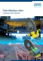
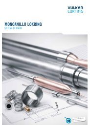
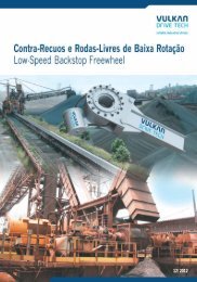
シリーズの 要 約SUMMARY OF SERIES<strong>VULASTIK</strong> L シリーズ/Series 2800SAE フライホイール J 620 とシャフトの 接 続 用 。For connecting an SAE flywheel J 620 to a shaft.説 明 / Description接 続 装 置 を 動 かすことによるエレメントの 交 換 。Replacement of elements by moving the adjacent machinery.寸 法 グループ kNm データシートのページDimens. Group kNm Data Sheet Page1410 0.40 12· ·· ·4310 20.00<strong>VULASTIK</strong> L シリーズ/Series 2802SAE フライホイール J 620 とハブまたはフランジの 接 続 用 。For connecting an SAE flywheel J 620 with a hub or flange.<strong>VULASTIK</strong> L シリーズ/Series 2801SAE フライホイール J 620 とシャフトの 接 続 用 。For connecting an SAE flywheel J 620 to a shaft.説 明 / Description接 続 装 置 を 動 かすことによるエレメントの 交 換ねじり 制 限 装 置 付 き。Replacement of elements by moving the adjacent machinery.With torsional limit device.寸 法 グループ kNm データシートのページDimens. Group kNm Data Sheet Page1410 0.40 12· ·· ·4310 20.00<strong>VULASTIK</strong> L シリーズ/Series 2803SAE フライホイール J 620 とハブまたはフランジの 接 続 用 。For connecting an SAE flywheel J 620 with a hub or flange.説 明 / DescriptionDIN 6281 に 準 拠 した 寸 法 。 接 続 装 置 を 動 かすことによるエレメントの 交 換 。(ハブなし)Dimensions conform to DIN 6281. Replacement of elements by movingthe adjacent machinery. (without hub)説 明 / DescriptionDIN 6281 に 準 拠 した 寸 法 。 接 続 装 置 を 動 かすことによるエレメントの 交 換 。ねじり 制 限 装 置 付 き。(ハブなし)Dimensions conform to DIN 6281. Replacement of elements by movingthe adjacent machinery. With torsional limit device. (without hub)寸 法 グループ kNm データシートのページDimens. Group kNm Data Sheet Page1410 0.40 12· ·· ·4310 20.00<strong>VULASTIK</strong> L シリーズ/Series 2810SAE フライホイール J 620 とシャフトの 接 続 用 。For connecting an SAE flywheel J 620 to a shaft.説 明 / Description接 続 装 置 を 動 かさないエレメントの 交 換 このエレメントはフランジケースと 制 限 リングを 動 かすことによって 垂 直 方 向に 取 り 外 すことができます。Replacement of elements without moving the adjacent machinery. Theelements can be removed vertically by moving the flanged casing.寸 法 グループ kNm データシートのページDimens. Group kNm Data Sheet Page2210 1.60 12· ·· ·4310 20.00<strong>VULASTIK</strong> L シリーズ/Series 2830シャフト 2 本 の 接 続 用 。For the connection of two shafts.説 明 / Description接 続 装 置 を 動 かさないエレメントの 交 換 このエレメントはフランジケースと 制 限 リングを 動 かすことによって 垂 直 方 向に 取 り 外 すことができます。Replacement of elements without moving the adjacent machinery. Theelements can be removed vertically by moving the flanged casing.寸 法 グループ kNm データシートのページDimens. Group kNm Data Sheet Page1410 0.40 12· ·· ·4310 20.00<strong>VULASTIK</strong> L シリーズ/Series 2811SAE フライホイール J 620 とシャフトの 接 続 用 。For connecting an SAE flywheel J 620 to a shaft.説 明 / Description接 続 装 置 を 動 かさないエレメントの 交 換 ねじり 制 限 装 置付 き。このエレメントとカムリングはフランジケースと 制 限リングを 動 かすことによって 半 径 方 向 に 取 り 外 すことができます。Replacement of elements without moving the adjacent machinery. Withtorsional limit device. The elements and the cam ring can be removedradially by moving the flanged casing and limit ring.寸 法 グループ kNm データシートのページDimens. Group kNm Data Sheet Page2210 1.60 12· ·· ·4310 20.00寸 法 グループ kNm データシートのページDimens. Group kNm Data Sheet Page2210 1.60 12· ·· ·4310 20.00<strong>VULASTIK</strong> L09
寸 法 / 質 量 - 慣 性 のモーメント/ 質 量DIMENSIONS/MASS-MOMENTS OF INERTIA/MASSES<strong>VULASTIK</strong> L シリーズ / Series 2800デザイン / Design A デザイン / Design B デザイン / Design C寸 法グループSAE J620フライホイールデザイン寸 法 [mm]質 量 慣 性 のモーメント質 量DimensionGroupFlywheel Design Dimensions [mm] Mass moment ofinertiaMassT KN D 1 D 2 D 3 D 4 L Kr S T L 1 L 2 L 3 L 4 L 5 F J 1 J 2 m 1 m 2kNmパイロットボア許 容最 大14100.40 - 8 A 263.50– 244.506 80.90 10.00–0.0201.400 7.90082.0010 B 314.40 20.00 60.00 118.00 263.00 293.50 11.00 73.00 34.00 –1.50 0.030 0.020 2.100 7.6000.50 810.0011 2 1 B 352.40 265.00 333.40 106.70 – 105.00 0.050 2.600 9.9000.63 - 10 A 314.40– 295.30 11.00 873.00 10.00 82.00 –0.050 0.030 2.400 9.900161011 2 1 B 352.40 25.00 70.00 136.0040.001.50315.00 333.40 106.70 – 0.060 0.040 2.800 13.2000.80 105.00 10.0014 B 466.70 438.20 14.00 92.40 – 0.180 0.030 6.400 12.30019101.00 - 11 2 1 A 352.40 – 333.40 11.0035.00 85.00 160.00 8 106.70 48.00 12.00 –0.0803.300 18.100105.00 1.500.0701.25 14 B 466.70 356.00 438.20 14.00 92.40 – 12.00 0.180 5.600 16.90022101.60 - 11 2 1 C 352.40 405.00 333.40 11.0035.00 95.00 190.00 8 106.70 76.00 11.00 105.00 12.00 0.2306.6001.500.1402.00 14 B 466.70 408.00 438.20 14.00 92.40 53.00 – 15.00 0.240 6.20024.10026102.50 - 14 A 466.70 110.00 – 438.20 14.00 8 92.40 20.00 –0.3507.600 32.60045.00 220.00 62.00 105.00 1.500.2503.15 18 B 571.50 120.00 470.00 542.90 17.00 6 82.70 – 18.00 0.590 11.100 31.80030104.00 - 14 A 466.70 – 438.20 14.00 8 92.40 20.00 105.00 –0.360 0.320 8.300 36.90050.00 120.00 220.00 80.00 2.005.00 18 B 571.50 466.00 542.90 17.00 6 135.00 – 135.00 20.00 0.660 0.390 12.700 47.4003210 6.3014 A 466.70 – 438.20 14.00 8 92.40 20.00 105.00 –0.450 0.300 10.300 35.90050.00 120.00 220.00 80.00 2.0018 B 571.50 466.00 542.90 17.00 12 135.00 – 145.00 20.00 0.680 0.420 13.300 49.5003110 7.50 14 A 466.70 50.00 120.00 220.00 – 438.20 14.00 16 172.00 162.00 20.00 145.00 – 2.00 0.900 0.500 21.500 54.10034106.30 - 18 A 571.50 – 542.90 15.00 –1.45060.00 130.00 185.00 17.00 12 150.00 109.00 150.00 2.000.880 21.300 8.00 21 B 673.10 571.00 641.40 – 15.00 2.020 27.40065.4003610 10.00 18 A 571.50 60.00 130.00 185.00 – 542.90 17.00 12 150.00 109.00 15.00 150.00 – 2.00 1.900 0.750 28.600 58.50037108.00 -10.0018 A 571.50 60.00 140.00 290.00 – 542.90 17.00 12 150.00 109.00 15.00 150.00 – 2.00 1.500 1.300 22.500 92.000401010.00 -12.5021 A 673.10 70.00 145.00 205.00 – 641.40 17.00 12 175.00 130.00 15.00 160.00 – 2.00 3.300 1.800 35.200 96.700431016.00-20.0021 A 673.10 70.00 170.00 235.00 – 641.40 17.00 12 195.00 170.00 15.00 190.00 – 2.00 4.470 2.550 48.400 127.800[kg m 2 ][kg]DIN 6281 に 準 拠 した 寸 法 。I. C. 原 動 機 駆 動 オルタネータは SAE J 620 を 基 準 。すべての 質 量 および 質 量 慣 性 モーメントは、パイロットボアハブを 参 照 します。Dimensions conform to DIN 6281, with reference to SAE J 620 for I. C. Prime Mover driven Alternators.All masses and mass moments of inertia refer to pilot bored hubs.10 <strong>VULASTIK</strong> L A/M 2800 (V. 2) 01/2012
<strong>VULASTIK</strong> L シリーズ / Series 2801デザイン / Design A デザイン / Design B デザイン / Design C寸 法グループSAE J620フライホイールデザイン寸 法 [mm]質 量 慣 性 のモーメント質 量DimensionGroupFlywheel Design Dimensions [mm] Mass momentof inertiaMassT KN D 1 D 2 D 3 D 4 D 5 L Kr S T L 1 L 2 L 3 L 4 L 5 F J 1 J 2 m 1 m 2kNmパイロットボア許 容最 大[kg m 2 ][kg]1410161019102210261030103410371040104310– 322.00 295.300.40 - 8 A 263.50– 270.00 244.50 6 80.90– 0.0403.200 8.20082.0010 B 314.40 20.00 60.00 118.0011.0043.00 5.001.50 0.020263.00 322.00 295.30 73.000.090 5.500 8.1000.50 819.0011 2 1 B 352.40 360.00 333.40 106.70 105.00 0.150 7.500 10.1000.63 - 10 A 314.4073.0082.00 – 0.1004.900 11.6000.8011.0011 2 1 B 352.40 25.00 70.00 136.00850.00 6.001.50 0.050314.00 360.00 333.40 106.70 0.190 8.500 14.800105.00 20.0014 B 466.70 475.00 438.20 14.00 92.40 0.540 16.400 14.8001.00 - 11 2 1 A 352.40 – 360.00 333.40 11.00 106.70 –35.00 85.00 160.00 858.00 6.00 105.00 1.50 0.140 5.500 20.1000.1001.25 14 B 466.70 352.00 475.00 438.20 14.00 92.40 22.00 0.570 16.400 19.7001.60 - 11 2 1 C 352.40 405.00 – 333.40 11.00 106.70 82.00 17.00 18.00 0.310 9.900 29.30035.00 95.00 190.00 8105.00 1.50 0.2102.00 14 B 466.70 408.00 475.00 438.20 14.00 92.40 68.00 8.00 30.00 0.660 15.700 26.9002.50 - 14 A 466.70 – 475.00 438.20 14.00 8 92.40 – 0.730 0.310 16.200 37.40045.00 110.00 220.00 77.00 8.00 105.00 1.503.15 18 B 571.50 466.00 582.00 542.90 17.00 6 97.70 33.00 1.960 0.300 35.300 37.8004.00 - 14 A 466.70 – 475.00 438.20 14.00 8 112.40 105.00 – 1.030 0.360 23.300 40.60050.00 120.00 220.00 100.00 14.00 2.005.00 18 B 571.50 466.00 582.00 542.90 17.00 6 135.00 135.00 40.00 2.090 0.440 37.800 49.5006.30 - 18 A 571.50 – 582.00 542.90 6–60.00 130.00 185.00 17.00 150.00 129.00 10.00 150.00 2.00 2.800 1.180 42.000 8.00 21 B 673.10 571.00 683.00 641.40 12 45.00 5.040 64.40077.1008.00 -10.0018 A 571.50 60.00 130.00 185.00 – 582.00 542.90 17.00 12 150.00 129.00 10.00 150.00 – 2.00 2.600 1.260 38.700 77.70010.00 -12.5021 A 673.10 70.00 145.00 205.00 – 685.00 641.40 17.00 12 175.00 155.00 15.00 160.00 – 2.00 6.420 2.630 69.300 123.20016.00-20.0021 A 673.10 70.00 170.00 235.00 680.00 685.00 641.40 17.00 12 221.00 195.00 15.00 190.00 – 2.00 6.900 3.200 75.000 148.000DIN 6281 に 準 拠 した 寸 法 。I. C. 原 動 機 駆 動 オルタネータは SAE J 620 を 基 準 。すべての 質 量 および 質 量 慣 性 モーメントは、パイロットボアハブを 参 照 します。Dimensions conform to DIN 6281, with reference to SAE J 620 for I. C. Prime Mover driven Alternators.All masses and mass moments of inertia refer to pilot bored hubs.A/M 2801 (V. 1) 01/2012<strong>VULASTIK</strong> L11
寸 法 / 質 量 - 慣 性 のモーメント/ 質 量DIMENSIONS/MASS-MOMENTS OF INERTIA/MASSES<strong>VULASTIK</strong> L シリーズ / Series 2802デザイン / Design A デザイン / Design B デザイン / Design C寸 法グループSAE J620フライホイールデザイン寸 法 [mm]質 量 慣 性 のモーメント質 量DimensionGroupFlywheel Design Dimensions [mm] Mass momentof inertiaMassT KN D 1 D 2 D 3 D 4 L Kr1 S 1 S 3 T 1 L Kr2 S 2 T 2 L 1 L 2 L 3 L 4 L 5 L 6 J 1 J 2 m 1 m 2kNm [kg m 2 ] [kg]0.40 - 8 A 263.50– 244.50– 69.00– 0.0201.400141010 B 314.40 118.00 82.00 295.30 11.00 – 8 102.00 11.00 12 9.00 34.00 10.00 9.00 25.00 – 0.030 0.010 2.100 1.3000.50 265.0011 2 1 B 352.40 333.40 – 8 9.20 – 0.050 2.6000.63 - 10 A 314.40– 295.30 11.00 –11.00– 0.0402.000 2.000161011 2 1 B 352.40 136.00 95.00 333.40 11.00 – 8 115.00 11.00 12 11.20 40.00 10.00 11.00 29.00 – 0.060 0.010 2.800 2.0000.80 315.0014 B 466.70 438.20 14.00 – 10.90 – 0.120 6.400 2.10019101.00 - 11 2 1 A 352.40 – 333.40 11.00 –160.00 110.00 8 135.00 14.00 12 14.70 – 0.090 3.40048.00 12.00 13.00 33.000.0201.25 14 B 466.70 352.00 438.20 14.00 – 14.40 – 0.240 7.9003.20022101.60 - 11 2 1 C 352.40 405.00 333.40 11.00 18.00190.00 132.00 8 160.00 16.00 12 37.70 76.00 11.00 15.00 38.00 12.00 6.6000.230 0.0502.00 14 B 466.70 408.00 438.20 14.00 – 14.90 53.00 15.00 – 6.1004.85026102.50 - 14 A 466.70 – 438.20 14.00 – 8 18.40220.00 155.00 190.00 18.00 12 62.00 20.00 – 0.320 7.11018.00 44.000.1103.15 18 B 571.50 466.00 542.90 17.00 – 6 18.70 18.00 – 0.820 15.7007.42030104.00 - 14 A 466.70 – 438.20 14.00 – 8 16.40– 0.360 8.300 220.00 160.00 190.00 18.00 16 80.00 20.00 22.00 70.000.160 10.5005.00 18 B 571.50 466.00 542.90 17.00 – 6 16.00 – 0.660 12.7003210 6.30 14 A 466.70 220.00 160.00 – 438.20 14.00 – 8 190.00 18.00 16 45.00 80.00 20.00 22.00 70.00 – 0.450 0.170 10.300 12.2003110 7.50 14 A 466.70 220.00 160.00 – 438.20 14.00 – 8 190.00 18.00 16 57.00 162.00 20.00 22.00 115.00 – 0.900 0.280 21.500 17.50034106.30 - 18 A 571.50 – 542.90 –290.00 205.00 17.00 12 250.00 22.00 16 49.00 109.00 15.00 – 1.380 20.80049.00 60.000.570 25.2008.00 21 B 673.10 571.00 641.40 – 25.00 – 2.020 27.4003610 10.00 18 A 571.50 290.00 205.00 – 542.90 17.00 – 12 250.00 22.00 16 25.00 109.00 15.00 25.00 75.00 – 1.490 0.500 22.400 21.70037108.00 -10.0018 A 571.50 300.00 205.00 – 542.90 17.00 – 12 250.00 22.00 16 29.00 109.00 15.00 29.00 86.00 – 1.600 0.500 23.700 19.100401010.00 -12.5021 A 673.10 335.00 235.00 – 641.40 17.00 – 12 285.00 24.00 16 54.00 130.00 15.00 54.00 76.00 – 3.270 1.280 35.500 41.100431016.00-20.0021 A 673.10 335.00 235.00 – 641.40 17.00 – 12 285.00 24.00 16 45.00 170.00 15.00 45.00 125.00 – 4.280 1.750 46.260 52.600DIN 6281 に 準 拠 した 寸 法 。I. C. 原 動 機 駆 動 オルタネータは SAE J 620 を 基 準 。すべての 質 量 および 質 量 慣 性 モーメントは、パイロットボアハブを 参 照 します。Dimensions conform to DIN 6281, with reference to SAE J 620 for I. C. Prime Mover driven Alternators.All masses and mass moments of inertia refer to pilot bored hubs.12 <strong>VULASTIK</strong> LA/M 2802 (V. 1) 01/2012
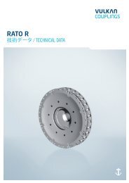
<strong>VULASTIK</strong> L シリーズ / Series 2810デザイン / Design Aデザイン / Design Bデザイン / Design Cデザイン / Design DA/M 2810 (V. 1) 01/2012 <strong>VULASTIK</strong> L 15
寸 法 / 質 量 - 慣 性 のモーメント/ 質 量DIMENSIONS/MASS-MOMENTS OF INERTIA/MASSES<strong>VULASTIK</strong> L シリーズ / Series 2811寸 法グループSAE J620フライホイール寸 法 [mm]質 量 慣 性 のモーメント質 量DimensionGroupFlywheel Dimensions [mm] Mass moment ofinertiaMassT KN D 1 D 2 D 3 D 5 L Kr S T L 1 L 2 L 3 L 4 F J 1 J 2 m 1 m 2kNmパイロットボア許 容最 大[kg m 2 ][kg]2610301034103710401043102.50 -3.1514 466.70 45.00 110.00 150.00 470.00 438.20 14.00 8 222.00 94.00 20.00 125.00 1.50 0.760 0.270 17.000 35.0004.00 - 14 466.70 438.20 14.00 8 259.00 121.00 20.001.060 24.10050.00 120.00 160.00 470.00 135.00 2.000.3405.00 18 571.50 542.90 17.00 6 272.00 134.00 20.00 1.500 31.70040.7006.30 - 18 571.50 542.9060.00 130.00 185.00 582.00 17.00 12 278.00 129.00 15.00 2.800 42.000150.00 2.001.2508.00 21 673.10 641.40 25.00 3.440 48.60081.5008.00 -10.0018 571.50 60.00 140.00 200.00 582.00 542.90 17.00 12 311.00 162.00 15.00 150.00 2.00 2.930 1.340 43.500 86.70010.00 -12.5021 673.10 70.00 145.00 205.00 685.00 641.40 17.00 12 325.00 155.00 15.00 175.00 2.00 6.420 2.460 69.300 116.00016.00-20.0021 673.10 70.00 170.00 235.00 685.00 641.40 17.00 12 382.00 195.00 15.00 190.00 2.00 7.040 3.360 76.700 157.200すべての 質 量 および 質 量 慣 性 モーメントは、パイロットボアハブを 参照 します。All masses and mass moments of inertia refer to pilot bored hubs.16 <strong>VULASTIK</strong> L 01/2012 (v. 1) !
注 意NOTES0102030405060708090100110120130140150160170180190200210 22018 <strong>VULASTIK</strong> L
注 意NOTES0102030405060708090100110120130140150160170180190200210 220
www.<strong>vulkan</strong>.com本 社 :VULKAN Kupplungs- und Getriebebau Bernhard Hackforth GmbH & Co. KG | Heerstraße 66 | 44653 Herne | Germany電 話 + 49 (0) 2325 922-0 | Fax + 49 (0) 2325 71110 | Eメール info.vkg@<strong>vulkan</strong>.com