Metallic Hose Assemblies - Thorburn Flex Inc
Metallic Hose Assemblies - Thorburn Flex Inc Metallic Hose Assemblies - Thorburn Flex Inc
Metal HoseCorrugatedType of hose 1st end 2nd end Hose size Length in inches* FractionsCoverXXX XX XX XX XXX XXType of hoseS61S62S62ZS65S66S66ZS95S96S96ZS91S92S92ZM95M96M96ZMDF150**MDF225**2S962S96Z2S922S92ZNS99ZThorburnEngineExhaustAssembliesOrder by: Partnumber; Endconnection;Pipe size, Boltpattern; Bolthole diameterFitting code numbers01- Male nipple carbon steel02- Male nipple 304SSHose size in1/16 of an inchExamples:Assemblylength ininches03- Male niple 316SS01=1/1602=1/8* For metric04- Hex male carbon steel04=1/4length, put05- Hex male 304SS06- Hex male 316SS06=3/8metric number08=1/2with the measurementtype.07- Female union carbon steel 150#12=3/408- Female union 304SS 150#64=4i.e. MM=09- Female union 316SS 150#etc.millimeters;10- Female 37 o 304SSM- meters, etc.11- Solid female pipe carbon steel12- Solid female pipe 304SSSpecial Monel fitting code13- Solid female pipe 316SSnumbers14- Weld nipple carbon steel15- Weld nipple 304SSM1- Monel male nipple16- Weld nipple 316SSM2- Monel hex male nipple17- Fixed flange carbon steel 150# M3- Monel female union18- Fixed flange 304SS 150#M4- Monel class 150 fixed flange19- Fixed flange 316SS 150#M5- Monel class 150 weld neck20- Weld neck flange carbon steel 150#flange21- Weld neck flange 304SS 150# M6- Lap joint flange class 150 steel22- Weld neck flange 316SS 150#with a Monel stub end23- Lap joint flange carbon steelM7- Lap joint flange class 15024- Lap joint flange and stub end 304SS316SS with a Monel stub end25- Lap joint flange and stub end 316SS M8- Lap joint flange class 15026- Lap joint flange carbon steelMoneland stub end 304SSwith Monel stub end27- Lap joint flange carbon steeland stub end 316SS28- 3000# male union - carbon steel29- 3000# male union - 304SS30- 3000# male union - 316SSORDERING FLANGES31- Male union - 316SS JIC w/adapter■ To order 300# flange, 600#32- Female union carbon steel 3000# flange, etc., use 150# assemblypart number and specify33- Female union 304SS 3000#34- Female union 316SS 3000#class 300# or 600# flange35- 150# CS male unionbelow part number.36- Female 37 o carbon steel37- Female JIC 37 o 316 stainless steel■ To order forged raised face38- Victaulic carbon steel39- Victaulic 304SSflanges A105 or A182 ANSI40- Victaulic grooveB16.5 Class 150, 300, 600,41- Sanitary Flange 316SSetc., please add "A" after theflange code ie: 17A, 19A, 20A.42- Male union - CS JIC w/adapter50- CGA 29550- CGA 295Quick couplings for Thorburn metal hose assemblies60- Met-O-Seal female*61- Met-O-Seal male*62- Met-O-Seal socket weld*63- Cam and Groove male shank E*64- Cam and Groove female coupler C*65- Cam and Groove elbow*66- Cam and Groove male elbow*67- Tank truck adapter*68- Vitaulic*69- Tube end*70- Pre swage bilok nut and sleeve*71- Pre-welded "O" seal gland and nut** Please specify materialFractions ofan inch in 1/8inchesExamples:01=1/802=1/404=1/206=3/407=7/8Cover CodesBlank if N/AInsulationFJ = Fry-SilJacketTS = Thor-SilSFS = SaturatedFibreGlassSleevingUCS = UnsaturatedCeramicSleevingSP = Sil-PonProtectionAF = ArmourFlexUnpackedAFP = Armour-FlexPackedLS12 =LockSection (x)LS16 =LockSection (x)LS20 =LockSection (x)LS24 =LockSection (x)LS32 =LockSection (x)(x) = Add suffixS4 = 304SSS5 = 321SSS6 = 316SSCarbon steelleave blankHow to Order Special Ends■ To order plate flanges orspecial ends, simply insertXX for 1st end, YY for 2ndend and specify.■ To specify Hex on unions,use union number and specifyHex below.12
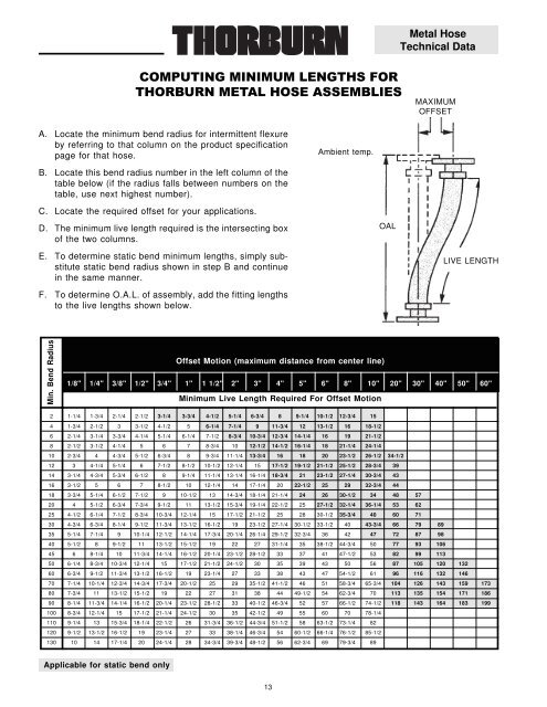
Metal HoseTechnical DataMAXIMUMOFFSETA. Locate the minimum bend radius for intermittent flexureby referring to that column on the product specificationpage for that hose.Ambient temp.B. Locate this bend radius number in the left column of thetable below (if the radius falls between numbers on thetable, use next highest number).C. Locate the required offset for your applications.D. The minimum live length required is the intersecting boxof the two columns.E. To determine static bend minimum lengths, simply substitutestatic bend radius shown in step B and continuein the same manner.F. To determine O.A.L. of assembly, add the fitting lengthsto the live lengths shown below.OALLIVE LENGTHMin. Bend RadiusOffset Motion (maximum distance from center line)1/8" 1/4" 3/8" 1/2" 3/4" 1" 1 1/2" 2" 3" 4" 5" 6" 8" 10" 20" 30" 40" 50" 60"Minimum Live Length Required For Offset Motion2 1-1/4 1-3/4 2-1/4 2-1/2 3-1/4 3-3/4 4-1/2 5-1/4 6-3/4 8 9-1/4 10-1/2 12-3/4 154 1-3/4 2-1/2 3 3-1/2 4-1/2 5 6-1/4 7-1/4 9 11-3/4 12 13-1/2 16 18-1/26 2-1/4 3-1/4 3-3/4 4-1/4 5-1/4 6-1/4 7-1/2 8-3/4 10-3/4 12-3/4 14-1/4 16 19 21-1/28 2-1/2 3-1/2 4-1/4 5 6 7 8-3/4 10 12-1/2 14-1/2 16-1/4 18 21-1/4 24-1/410 2-3/4 4 4-3/4 5-1/2 6-3/4 8 9-3/4 11-1/4 13-3/4 16 18 20 23-1/2 26-1/2 34-1/212 3 4-1/4 5-1/4 6 7-1/2 8-1/2 10-1/2 12-1/4 15 17-1/2 19-1/2 21-1/2 25-1/2 28-3/4 3914 3-1/4 4-3/4 5-3/4 6-1/2 8 9-1/4 11-1/4 13-1/4 16-1/4 18-3/4 21 23-1/2 27-1/4 30-3/4 4316 3-1/2 5 6 7 8-1/2 10 12-1/4 14 17-1/4 20 22-1/2 25 29 32-3/4 4418 3-3/4 5-1/4 6-1/2 7-1/2 9 10-1/2 13 14-3/4 18-1/4 21-1/4 24 26 30-1/2 34 48 5720 4 5-1/2 6-3/4 7-3/4 9-1/2 11 13-1/2 15-3/4 19-1/4 22-1/2 25 27-1/2 32-1/4 36-1/4 53 6225 4-1/2 6-1/4 7-1/2 8-3/4 10-3/4 12-1/4 15 17-1/2 21-1/2 25 28 30-1/2 35-3/4 40 60 7130 4-3/4 6-3/4 8-1/4 9-1/2 11-3/4 13-1/2 16-1/2 19 23-1/2 27-1/4 30-1/2 33-1/2 40 43-3/4 66 79 8935 5-1/4 7-1/4 9 10-1/4 12-1/2 14-1/4 17-3/4 20-1/4 26-1/4 29-1/2 32-3/4 36 42 47 72 87 9840 5-1/2 8 9-1/2 11 13-1/2 15-1/2 19 22 27 31-1/4 35 38-1/2 44-3/4 50 77 93 10645 6 8-1/4 10 11-3/4 14-1/4 16-1/2 20-1/4 23-1/2 28-1/2 33 37 41 47-1/2 53 82 99 11350 6-1/4 8-3/4 10-3/4 12-1/4 15 17-1/2 21-1/2 24-1/2 30 35 39 43 50 56 87 105 120 13260 6-3/4 9-1/2 11-3/4 13-1/2 16-1/2 19 23-1/4 27 33 38 43 47 54-1/2 61 96 116 132 14670 7-1/4 10-1/4 12-3/4 14-3/4 17-3/4 20-1/2 25 29 35-1/2 41-1/2 46 51 58-3/4 65-3/4 104 126 143 159 17380 7-3/4 11 13-1/2 15-1/2 19 22 27 31 38 44 49-1/2 54 62-3/4 70 113 135 154 171 18690 8-1/4 11-3/4 14-1/4 16-1/2 20-1/4 23-1/2 28-1/2 33 40-1/2 46-3/4 52 57 66-1/2 74-1/2 118 143 164 183 199100 8-3/4 12-1/4 15 17-1/2 21-1/4 24-1/2 30 35 42-1/2 49 55 60 70 78-1/4110 9-1/4 13 15-3/4 18-1/4 22-1/2 26 31-3/4 36-1/2 44-3/4 51-1/2 58 63-1/2 73-1/4 82120 9-1/2 13-1/2 16-1/2 19 23-1/4 27 33 38-1/4 46-3/4 54 60-1/2 66-1/4 76-1/2 85-1/2130 10 14 17-1/4 20 24-1/4 28 34-3/4 39-3/4 48-1/2 56 62-3/4 69 79-3/4 89Applicable for static bend only13
- Page 4 and 5: Metal HoseCorrugatedCUSTOM METAL HO
- Page 6 and 7: Metal HoseCorrugatedExtra Flexible
- Page 8 and 9: Metal HoseCorrugatedHeavy Duty Cons
- Page 10 and 11: Metal HoseCorrugatedCompressedcorru
- Page 12 and 13: Metal HoseCorrugated Hose Thread O
- Page 16 and 17: Metal HoseTechnical Data Minimu
- Page 18 and 19: Metal HoseTechnical DataA piping sy
- Page 20 and 21: Metal HoseTechnical DataExamples:A
- Page 22 and 23: Metal HoseLock SectionSize I.D. O.D
- Page 24 and 25: Metal HoseLock SectionStripwound ho
- Page 26 and 27: Metal HoseLock SectionAF (unpacked)
- Page 28 and 29: Metal HoseSmooth Lock Section BoreS
- Page 30 and 31: Teflon Lined Hose■ Chemical Inert
- Page 32 and 33: Teflon Lined HoseAerosol PackagingF
- Page 34 and 35: Teflon Lined HoseThorburn TS series
- Page 36 and 37: Teflon Lined HoseFEMALE PIPETUBE EN
- Page 38 and 39: Teflon Lined HoseThorburn's TSX16 h
- Page 40 and 41: Teflon Lined HoseThe drawback found
- Page 42 and 43: Teflon Lined HoseThorburn's TC72 an
- Page 44 and 45: Teflon Lined Hose■■■Electrica
- Page 46 and 47: Teflon Lined HoseMaterials Male pip
- Page 48 and 49: Teflon Lined HoseThorburn introduce
- Page 50 and 51: Teflon Lined HoseHose TypeJ - T46F
- Page 52 and 53: Teflon Lined HoseHose Fitting Mater
- Page 54 and 55: Teflon Lined Hose45°ESAE 45° INVE
- Page 56 and 57: Teflon Lined HoseStainless steelcon
- Page 58 and 59: Teflon LinedTeflon Lined HoseMetal
- Page 60 and 61: Thermal InsulationProtectionProduct
- Page 62 and 63: Thermal InsulationProtection THERM
Metal <strong>Hose</strong>Technical DataMAXIMUMOFFSETA. Locate the minimum bend radius for intermittent flexureby referring to that column on the product specificationpage for that hose.Ambient temp.B. Locate this bend radius number in the left column of thetable below (if the radius falls between numbers on thetable, use next highest number).C. Locate the required offset for your applications.D. The minimum live length required is the intersecting boxof the two columns.E. To determine static bend minimum lengths, simply substitutestatic bend radius shown in step B and continuein the same manner.F. To determine O.A.L. of assembly, add the fitting lengthsto the live lengths shown below.OALLIVE LENGTHMin. Bend RadiusOffset Motion (maximum distance from center line)1/8" 1/4" 3/8" 1/2" 3/4" 1" 1 1/2" 2" 3" 4" 5" 6" 8" 10" 20" 30" 40" 50" 60"Minimum Live Length Required For Offset Motion2 1-1/4 1-3/4 2-1/4 2-1/2 3-1/4 3-3/4 4-1/2 5-1/4 6-3/4 8 9-1/4 10-1/2 12-3/4 154 1-3/4 2-1/2 3 3-1/2 4-1/2 5 6-1/4 7-1/4 9 11-3/4 12 13-1/2 16 18-1/26 2-1/4 3-1/4 3-3/4 4-1/4 5-1/4 6-1/4 7-1/2 8-3/4 10-3/4 12-3/4 14-1/4 16 19 21-1/28 2-1/2 3-1/2 4-1/4 5 6 7 8-3/4 10 12-1/2 14-1/2 16-1/4 18 21-1/4 24-1/410 2-3/4 4 4-3/4 5-1/2 6-3/4 8 9-3/4 11-1/4 13-3/4 16 18 20 23-1/2 26-1/2 34-1/212 3 4-1/4 5-1/4 6 7-1/2 8-1/2 10-1/2 12-1/4 15 17-1/2 19-1/2 21-1/2 25-1/2 28-3/4 3914 3-1/4 4-3/4 5-3/4 6-1/2 8 9-1/4 11-1/4 13-1/4 16-1/4 18-3/4 21 23-1/2 27-1/4 30-3/4 4316 3-1/2 5 6 7 8-1/2 10 12-1/4 14 17-1/4 20 22-1/2 25 29 32-3/4 4418 3-3/4 5-1/4 6-1/2 7-1/2 9 10-1/2 13 14-3/4 18-1/4 21-1/4 24 26 30-1/2 34 48 5720 4 5-1/2 6-3/4 7-3/4 9-1/2 11 13-1/2 15-3/4 19-1/4 22-1/2 25 27-1/2 32-1/4 36-1/4 53 6225 4-1/2 6-1/4 7-1/2 8-3/4 10-3/4 12-1/4 15 17-1/2 21-1/2 25 28 30-1/2 35-3/4 40 60 7130 4-3/4 6-3/4 8-1/4 9-1/2 11-3/4 13-1/2 16-1/2 19 23-1/2 27-1/4 30-1/2 33-1/2 40 43-3/4 66 79 8935 5-1/4 7-1/4 9 10-1/4 12-1/2 14-1/4 17-3/4 20-1/4 26-1/4 29-1/2 32-3/4 36 42 47 72 87 9840 5-1/2 8 9-1/2 11 13-1/2 15-1/2 19 22 27 31-1/4 35 38-1/2 44-3/4 50 77 93 10645 6 8-1/4 10 11-3/4 14-1/4 16-1/2 20-1/4 23-1/2 28-1/2 33 37 41 47-1/2 53 82 99 11350 6-1/4 8-3/4 10-3/4 12-1/4 15 17-1/2 21-1/2 24-1/2 30 35 39 43 50 56 87 105 120 13260 6-3/4 9-1/2 11-3/4 13-1/2 16-1/2 19 23-1/4 27 33 38 43 47 54-1/2 61 96 116 132 14670 7-1/4 10-1/4 12-3/4 14-3/4 17-3/4 20-1/2 25 29 35-1/2 41-1/2 46 51 58-3/4 65-3/4 104 126 143 159 17380 7-3/4 11 13-1/2 15-1/2 19 22 27 31 38 44 49-1/2 54 62-3/4 70 113 135 154 171 18690 8-1/4 11-3/4 14-1/4 16-1/2 20-1/4 23-1/2 28-1/2 33 40-1/2 46-3/4 52 57 66-1/2 74-1/2 118 143 164 183 199100 8-3/4 12-1/4 15 17-1/2 21-1/4 24-1/2 30 35 42-1/2 49 55 60 70 78-1/4110 9-1/4 13 15-3/4 18-1/4 22-1/2 26 31-3/4 36-1/2 44-3/4 51-1/2 58 63-1/2 73-1/4 82120 9-1/2 13-1/2 16-1/2 19 23-1/4 27 33 38-1/4 46-3/4 54 60-1/2 66-1/4 76-1/2 85-1/2130 10 14 17-1/4 20 24-1/4 28 34-3/4 39-3/4 48-1/2 56 62-3/4 69 79-3/4 89Applicable for static bend only13


