Mudrocks - Sultan Qaboos University
Mudrocks - Sultan Qaboos University
Mudrocks - Sultan Qaboos University
- No tags were found...

You also want an ePaper? Increase the reach of your titles
YUMPU automatically turns print PDFs into web optimized ePapers that Google loves.
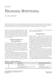
CLASSIFICATION SYSTEMS OF MUDROCKSstorm wave base levels (Potter et al., 1980). In addition, mudrocks can form in lakes and in quiet-waterparts of rivers and in lagoonal, tidal-flat, and deltaic environments (Boggs, 1987).<strong>Mudrocks</strong> are by far the most abundant type of sedimentary rocks. This is because of the fine-grainedsilici-clastic products of weathering which greatly exceed coarser particles. <strong>Mudrocks</strong> commonly occurinterbedded with sandstones and limestones in units ranging in thickness from a few millimeters to tens ofmetres. Some varieties of mudrocks (e.g. shales) are found to be hundreds of metres thick with widespreadareal extent (Boggs, 1987).3. Geological TerminologyThe term “mudrock” generally refers to fine-grained sedimentary rocks and includes shales,mudstones, claystones and siltstones. However, there is a lack of agreement among researchers on theclassification of fine-grained sedimentary rocks due to their wide range of geological and engineeringcharacteristics. The main sources of ambiguities are:(a) The term “shale” can be used in a restricted sense as a fissile or laminated rock, (Tourtelot, 1960). Ithas also been used as a group name for all fine-grained sedimentary rocks by many authors, (Grainger,1984).(b) The use of the term “mudrock” in engineering geology to encompass argillaceous engineering “rocks”as opposed to clay “soils”, (De Freitas, 1981; Taylor and Spears, 1981).(c) There is a lack of agreement on both the grain size definition and grain size distribution for siltstones,mudstones and claystones.To avoid this confusion, it is suggested that the term “Mudrock” be used as a general group name andthe term “Shale” be restricted to the fissile or laminated rocks, (Ingram, 1953; Blatt et al., 1972; Spears,1980; Taylor and Spears, 1981). Therefore, the terms “Mudstone”, “Siltstone” and “Claystone” should berestricted to non-fissile rocks (Clark, 1954).Grainger (1984) proposed a broad definition which includes all fine-grained soils and considers grainsize, mineral composition, texture and compressive strength. Mudrock is defined as fine to very finegrainedsilici-clastic sediment or sedimentary rock. Further, the descriptive terms of this definition havebeen quantitatively defined as shown in Figure 1.Since natural materials encountered in practice are borderline and difficult to classify as either “hardsoil” or “soft rock”, it is suggested that a broad definition of mudrocks is used and includes engineering claysoils. This preference is supported by the fact that a competent mudstone at surface may well behave like aclay in a deep mining situation. The inclusion of clay soils in the definition of mudrocks has beenpreviously suggested by Taylor and Spears (1981) and Grainger (1984).4. Mudrock Classifications<strong>Mudrocks</strong> may be classified into different types based on their geological and engineering properties.The identification of the most useful and relevant index rock properties is of prime importance, asdescription of lithology alone can lead to gross errors, (Olivier, 1979). Some of the other prerequisites forrock classification are mentioned by Franklin (1970) and Bieniawski (1974a). They suggested thatclassification should be:1. Based on measurable parameters which can be determined by relevant tests quickly and cheaply inthe field.2. Involve only rapid testing techniques which are able to cope with a large number of routine samples.3. Testing techniques should be simple enough to be carried out by semi-skilled field laboratory staff.4. The range of test results values should allow for a sufficient power of discrimination when applied tovarious test samples.139
AL-RAWAS, CHEEMA, and AL-AGHBARI1. Grain size distribution- sieving- thin sectionSAMPLE> 35 < 35% of grains < 60 µm (by wt.)2. Composition- chemical analysis- XRD- thin section> 65Non-mudrock(sandstone, etc)< 65% of total wt. = silicates% of total wt. = quartz + clay3. Texture- SEM- thin section> 50> 50Non-mudrock(limestone, etc)< 50Non-mudrock(tuff, etc)< 50% of total wt. = clastic grainsNon-mudrock(chert, etc)4. Compressive strengthperpendicular to fabric- unconfined compression- Point load- cone Indenter< 100> 100Non-mudrock(slate, argillite, etc)σ c (MN/m 2 )MUDROCKFigure 1. The definition of mudrock (Grainger, 1984).140
CLASSIFICATION SYSTEMS OF MUDROCKSKeeping in mind the above mentioned recommendations, classification based on geological propertiessuch as grain size and mineralogy are reviewed here. Similarly, engineering index properties worthconsidering are strength, durability, swelling and plasticity characteristics. Since geological propertiescontrol the engineering behaviour of rocks, (Vutukuri et al., 1974; Tsidzi, 1990), they are discussed first.4.1 Grain Size ClassificationsGrain size is an important parameter in the classification of mudrocks. Purnell and Netterberg (1975)presented Table 1 summarizing some of the commonly used geologic classifications. Table 1 was extendedto cover the classification proposed by Pettijohn (1975). The classifications differ mainly in the use of thegroup term. The classifications of Ingram (1953), Pettijohn (1957), and Blatt et al. (1972) use mudrock asthe group term, whereas those of Twenhofel (1939) and Pettijohn (1975) use mudstone and argillaceoussediment, respectively.Grain size classification requires the determination of clay size fraction which is normally done bycarrying out a grain size distribution analysis. The procedure is described in British Standard 1377 (1990)and in D-422 (ASTM, 1990) and involves wet sieving and hydrometer analysis. For indurated mudrocks,samples have to disaggregated first by cycles of wetting and drying as crushing will break the original clayminerals (Spears, 1980). Poorly indurated mudrocks may disaggregate after one or two cycles, whereas wellindurated mudrocks may require up to eight cycles (Dick et al., 1994).Table 1. Some geological classifications of mudrocks (1) (Purnell and Netterberg 1975).Notes: (1) Mudrock : sedimentary rock composed of at least 50% silt plus clay, with no restriction as totheir relative amounts or as to the breaking characteristics (Ingram 1953).(2) An indurated material is strictly only one which does not slake (disintegrate) in air or water.(3) An argillite is a rock indurated by slight metamorphism to a material between a mudrock properand a slate. The term is generally used for rock which is none-fissile (Clark 1954), but if fissile,does not yet possess the slaty cleavage of a slate.(4) The particle size of > 0.01 mm is used for the definition of siltstone.4.2 Mineralogical ClassificationsThe mineralogical composition of mudrocks plays an important role in their behavior, particularly the“soil-like” mudrocks. Without a thorough understanding of the mineralogical composition, engineering141
CLASSIFICATION SYSTEMS OF MUDROCKSDeere and Miller (1966) proposed a scheme based on a plot of the uniaxial compression strength(UCS) and tangent modulus of deformation. The scheme divides the strength of mudrocks into four zones:very low (UCS < 25 MN/m 2 ), low (UCS 25-50 MN/m 2 ), medium (UCS 50-100 MN/m 2 ) and high (UCS >100 MN/m 2 ). Similarly, the UCS values of as low as 0.17 MN/m 2 for weak mudrocks and as high as 103MN/m 2 for well cemented mudrocks are reported by Underwood (1967).Morgenstern and Eigenbrod (1974) conducted strength softening tests on 14 different mudrocks. Theyclassified mudrocks into mudstones, hard clays, stiff clays, and medium clays.Another classification system based on uniaxial compression strength (UCS) was proposed by theUnited Kingdom Geological Society Working Party Report (Anon, 1977). The system classifies mudrocksinto four classes: a very soft rock (UCS < 40 kN/m 2 ), a very weak rock or hard soil (UCS 0.6-1.25 MN/m 2 ),a weak rock (UCS 1.25-100 MN/m 2 ) and a very strong rock (UCS > 100 MN/m 2 ). Grainger (1984)proposed yet another mudrock classification based on the uniaxial compressive strength values. The UCSvalues of 0.6 MN/m 2 , 3.6 MN/m 2 , and 100 MN/m 2 were proposed as boundaries between fine-grained soillike mudrocks, non-indurated mudrocks, and indurated mudrocks, respectively.4.4 Testing ProceduresDepending upon the type of mudrock, different strength test procedures have been recommended. Forvery weak mudrocks (or clayey soils), Grainger (1984) recommends the straightforward undrained triaxialmethod of compression testing as specified by Morgenstern and Eigenbrod (1974). However for strongerindurated mudrocks, the uniaxial compression strength (UCS) is suggested.The choice of uniaxial compressive strength (UCS) for mudrock classification is based on the fact theUCS is the most widely used design parameter in rock engineering. It has been used in most rock massclassification systems for engineering purposes, (Bieniawski, 1973; Barton et al., 1974; Laubscher, 1977),and is an important parameter in rock mass strength criterion, (Hoek and Brown, 1980). The uniaxialcompressive strength is also used in estimating workability of rock, (Franklin et al., 1971; Wood, 1972),evaluating the use of rock as a construction material, and predicting the utilization possibilities of a tunnelboring machine (Jenni and Balissat, 1979). According to a survey reported by Bieniawski (1974b), miningengineers request the Uniaxial Compressive Strength more often than any other rock material property.The procedure for the Uniaxial Compressive Strength Test has been standardized by both theInternational Society for Rock Mechanics (ISRM) and the American Society for Testing and Materials(ASTM) Designation D-2938-71a. The mudrock core sample of length twice the diameter ratio is tested inan uniaxial testing machine.Although, the procedure to determine UCS by using UCS testing machine is simple, it requiressophisticated laboratory equipment and meticulously prepared rock cores of specific dimensions. Theserock cores are not always available. Also, loosely cemented, poorly indurated, and highly laminatedmudrocks disintegrate during drilling process, making it almost impossible to obtain core samples even withspecial drilling techniques. As a result, determination of compressive strength by standard procedures tendsto be expensive, time consuming, tedious, and sometimes impossible. The problem is further compoundedby the fact that mudrocks disintegrate during the drilling process making it almost impossible to obtain coresamples even with special drilling techniques. This limitation lured the researchers (Olivier, 1976; Grainger,1984) to recommend point load testing for the indirect determination of uniaxial compressive strength.The Point Load Test measures the point load index (Is) which is multiplied by a conversion factor "k"in order to obtain the uniaxial compressive strength of a rock. This k value not only depends on the rocktype but also on the sample size and shape. The widely accepted k value for most rocks is 24 for 54 mmdiameter core (Broch and Franklin, 1972). However, for mudrocks, k values of as low as 8 to as high as 35are reported (Carter and Sneddon, 1977, Norbury 1986).Cheema (1993) performed point load tests on cube-shaped pieces of different mudrock samples. Theprocedure involved cutting first 15 to 20 pieces of each mudrock sample by a thin-bladed rocksaw, andthen, testing by using a Point Load Tester. They followed the procedure as described by Broch and Franklin143
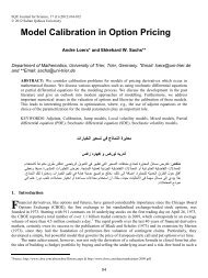
AL-RAWAS, CHEEMA, and AL-AGHBARI(1972). However, because of the penetration of cones in the soft mudrocks, the distance in between theplatens (D) was measured after the penetration and was used while calculating the point load index. Cheema(1993) calculated the point load index (Is) by the following formula:Is = P/D²where P is the applied load and D is the distance between the platens after penetration.The mudrock classifications based on the compressive strength by Deere and Miller (1966) and theUnited Kingdom Geological Society Working Party Report (Anon, 1977) systems are of limited valuebecause their use of the compressive strength as the sole classification parameter and therefore, they areunable to differentiate between rocks of variable durability.4.5 Durability ClassificationsDurability is a property that indicates the ability of mudrocks to withstand disintegration due toweathering. Durability can be evaluated by the slake durability index test (Franklin and Chandra, 1972), therate of slaking test (Morgenstern and Eigenbrod, 1974), the modified soundness test (Wood and Deo, 1975)and the simple slake test (Stollar, 1976). However, the slake durability index test is the most widely usedtest (Dick et al., 1994).Example:Durability (2 cycle) = 70Plasticity index = 5Plotted position •Classified as medium durability - low plasticityPlasticity index, PIHighMediumLow251000.1Very low30Low60•Medium2 - cycle slaking durability, I d 2 ,% retained10085 95 98Med.highVeryHigh highFigure 2. Durability-plasticity chart of Gamble (1971).144
CLASSIFICATION SYSTEMS OF MUDROCKSSeveral classification systems were developed to assess the durability behavior of mudrocks. Gamble(1971) developed a durability-plasticity chart (Figure 2) for mudrocks based on two-cycle slake durabilitytests. The chart divides durability into six classes: very low, low, medium, medium high, high and very high.Taylor and Spears (1981) suggested the adoption of Gamble’s (1971) classification for less indurated typesof mudrocks. Morgenstern and Eigenbrod (1974) developed a durability classification system based onliquid limit and rate of slaking values.Olivier (1979) developed a classification system based on a plot of the swelling coefficient (freeswelling from an oven-dry to a saturated condition) against uniaxial compressive strength (Figure 3). Thesystem recognizes six rock durability classes: excellent (class A), good (class B), fair (class C), moderatelypoor (class D), poor (class E) and very poor (class F). The system is particularly relevant to compacted andweakly cemented rocks. The major limitations of the system are the heterogeneous sedimentary rock massesand the variation of strength and free swelling properties of the rock material. Taylor and Spears (1981)indicated that Olivier’s (1979) classification seems to be a promising approach for moderately strong tovery strong mudrock types.0.1101001000Swelling Coefficient0. 010.0010. 0001Very LowLowMed.HighVery HighUniaxial Compressive Strength (MN / m 2 )Figure 3 . Durability classification of Olivier ( 1979 )Strohm (1980) developed a durability classification system for highway embankment design based onlithologic characteristics, durability tests and field performance of mudrocks used in the construction ofhighways in the United States. Franklin (1983) proposed a quantitative rating system based on second-cycleslake durability index (Id 2 ), plasticity index (PI), and point load strength index (Is 50 ).Grainger (1984) developed a classification scheme based on strength and durability, (Figure 4), whichrecognized three classes of mudrocks: soil-like mudrocks, non - durable mudrocks and durable mudrocks. Acompressive strength of 0.6 MN/m 2 is taken to be the upper limit of soil-like mudrocks. A non-durable rockhas a compressive strength of 0.6-3.6 MN/m 2 or 3.6-100 MN/m 2 and a slake durability less than 90%.145
AL-RAWAS, CHEEMA, and AL-AGHBARI5. Compressive strengthperpendicular to fabric- quick undrainedtriaxial compressionMUDROCKσ c (MN/m 2 )< 0.6 0.6-3.63.6-1006. Durability- 2 - cycle slakedurability test< 90> 90Slake durability %SOILNON-DURABLEROCKDURABLEROCKFigure 4. The classification of mudrock by strength and durability (Grainger, 1984).A compressive strength of 3.6-100 MN/m 2 and a slake durability greater than 90% is recommended for adurable rock. Grainger’s (1984) classification has the advantage of using both strength and durability,however, it lacks the description of the quality of mudrocks. Further, the compressive strength of 0.6MN/m 2 proposed by Grainger’s (1984) system as the upper limit of soil-like mudrocks is markedly lowerthan its equivalent proposed by the Working Party Report (Anon, 1977). Further classifications by Grainger(1984) using the quartz content, (determined by XRD analysis), and the flakiness ratio for the classificationof non-durable and durable mudrocks are shown in Figures 5 and 6 respectively.Dick et al. (1994) proposed a new durability classification based on lithologic characteristics, (Table3), in which durability is classified into three classes: low, medium and high. The second-cycle slakedurability index (Id 2 ) was used as a measure of the durability, whereas clay content, clay-mineralcomposition, texture, microfracture frequency, absorption, adsorption, dry density, void ratio, and Atterberglimits were used to characterize mudrock lithology. The classification requires an initial geologicclassification of mudrocks into claystones, mudstones, shales, etc. using the Potter et al. (1980) before theuse of the system. According to this classification, all claystones and mudstones with slickensided featureshave low durability, (Id 2 < 50%), whereas mudstones characterized by the presence of rough-surfacedmicrofractures, shales and siltstones have low, (Id 2 < 50%), to high, (Id 2 > 85%), durability.Table 3. Mudrock-durability classification system based on lithologic characteristics (Dick et al. 1994).Durability ClaystoneMudstone Shale Combined ArgilliteSiltstone-siltshaleSlickensidedImf (microfractures/cm)Absorption (%) Absorption(%)High: Id 2 > 85% NA NA < 0.4 < 5.5 < 5 AllMedium: 50 < Id 2 NA NA 0.8-0.4 10-5.5 9.5-5 NA< 85%Low: Id 2 < 50% All All > 0.8 > 10 >9.5 NA146
CLASSIFICATION SYSTEMS OF MUDROCKS10. Composition- XRD analysisNON-DURABLE MUDROCK% of total wt. = quartz< 20 20-40 > 4011. Anisotropy- fragment dimensions< 2/3< 2/3< 2/3> 2/3flakiness ratio c/bNONDURABLECLAYSTONESILTYCLAYSHALENON-DURABLESILTSTONECLAYSHALENON-DURABLEMUDSTONEFigure 5: The classification of non-durable mudrock (Grainger, 1984).12. Composition- XRD analysisDURABLE MUDROCK% of total wt. = quartz13. Anisotropy- point load- cone Indenter< 20 20-40< 2 > 2 > 2 < 2> 40Max. strength /min. strengthDURABLECLAYSTONESILTYSHALEDURABLESILTSTONESHALEDURABLEMUDSTONEFigure 6. The classification of durable mudrock (Grainger, 1984).147
AL-RAWAS, CHEEMA, and AL-AGHBARI4.6 Swelling Potential ClassificationsThe first step in dealing with expansive sediments or sedimentary rocks is to identify their capacity forvolume change. Once rocks have been identified as expansive, a quantitative characterization of theirswelling potential is necessary for design predictions. Unfortunately, there is no standard definition of theterm swelling potential, available in the literature, (Holtz, 1959; Seed et al., 1962; Snethen, 1979). Further,there is no standard swelling potential test, and therefore, it is difficult to make reliable comparisonsbetween results from different sources. The swelling potential of a soil or a rock can be simply defined as ameasure of its ability to swell or the pressure required to prevent swelling.Table 4. Shrinkage limit and linear shrinkage guide to potential expansion (after Altmeyer,1955).Shrinkage limit as a percentage Linear shrinkage as a percentage Degree of expansion8 Critical10-12 5-8 Marginal>12 0-5 NoncriticalTable 5. Data for making estimates of probable volume change for expansive soils (after Holtz andGibbs, 1956).Data from Index Tests*Probable expansion (% Degree ofColloid Content (% Plasticity Shrinkage total volume change) expansionminus 0.001 mm) index (%) limit (%)>28 >35 30 Very high20-31 25-41 7-12 20-30 High13-23 15-28 10-16 10-20 Medium60 >30 >10 Very high60-95 40-60 20-30 3-10 High30-60 30-40 10-20 1-5 Medium
CLASSIFICATION SYSTEMS OF MUDROCKSTable 7. Swelling potential classification based on plasticity index (after Chen, 1988).Swelling potential Plasticity index (%)low 0-15Medium 10-35High 20-55Very high35 and aboveAtterberg limits, clay content and activity are widely used for indirect quantification of mudrocksswell potential. Many classifications systems provide qualitative assessment of the degree of expansionsuch as low, medium, high and very high, or noncritical, marginal and critical. Altmeyer (1955) developed acriteria based on shrinkage limit and linear shrinkage as given in Table 4. However, recent research failed toshow conclusive evidence of the correlation between swelling potential and shrinkage limit (Chen, 1988).Holtz and Gibbs (1956) proposed a classification system based on Atterberg limits and clay content asshown in Table 5. Chen (1965) developed a classification based on percent passing the No. 200 sieve size,liquid limit and standard penetration resistance (Table 6). He also developed a criteria for the estimation ofswelling potential based on plasticity index alone as given in Table 7, (Chen, 1988).Seed et al. (1962) established a relationship between the percentage of clay sizes, activity andswelling potential (Figure 7) based on tests done on clays compacted to maximum density at optimumwater content according to the American Association of State Highway Officials (AASHTO). Raman(1967) proposed a classification for the degree of expansion based on plasticity index and shrinkage index(Table 8). Dakshanamurthy and Raman (1973) proposed a classification scheme based on liquid limit alone(Table 9). Van der Merwe (1975) developed a chart for determining expansiveness of soils, (Figure 8),based on plasticity index and clay content.87Activity6543HighVery High210MedLow0 10 20 30 40 50 60 70 80 90 100Clay Fraction (% < 0.002 mm)Figure 7. Swelling potential classification (Seed et al ., 1962).149
AL-RAWAS, CHEEMA, and AL-AGHBARITable 8. Degree of expansion classification based on plasticity index and shrinkage index (afterRaman, 1967).Plasticity index (%) Shrinkage index (%) Degree of expansion40 Very highTable 9. Swelling potential classification based on liquid limit (after Dakshnaamurthy and Raman,1973).Swelling potential Liquid limit (%)None 0-20Low 20-35Medium 35-50High 50-70Very high 70-90Extra high >90(%)Plasticity Index80706050403020100A=2.0 A=1.0 A=0.7Very HighA=0.6A=0.5HighA=ActivityMediumLow0 10 20 30 40 50 60 70 80 90 100Clay Fraction (%
CLASSIFICATION SYSTEMS OF MUDROCKSand plasticity index and in situ soil suction as an indicator of natural conditions and environment, (Table10).Table 10. Degree of expansion based on liquid limit, plasticity index, and in situ suction (after Snethenet al., 1977).Liquid limit (%) Plasticity index (%) Soil Suction * Potential swell Potential swellclassification>60 >35 >4 >1.5 High50-60 25-35 1.5-4 0.5-1.5 Marginal
AL-RAWAS, CHEEMA, and AL-AGHBARIrocks swell potential, but the reliance on such empirical systems can be misleading. Nelson and Miller(1992) indicated that the use of such systems has led to overly conservative construction in some places andinadequate construction in others. Prediction testing and analysis are needed to provide reliable informationon which to base design decisions.Various methods have been reported in the literature for the measurement of soils and rocks swellingpotential. The most common methods include the swell-consolidation method, loaded-swell method andconstant volume method, which utilize the one-dimensional consolidation oedometer (Jennings and Knight,1957; Komornik, and David, 1969; Al-Rawas 1999). Other methods for estimating swelling potential usesoil suction (McKeen and Hamberg, 1981). These methods include tensiometers, axis translation, filterpaper, thermocouple psychrometers and thermal matric potential sensors. Nelson and Miller (1992)provided good summary of common methods in use for estimating soils and rocks swelling potential.4.7 Soil-Like <strong>Mudrocks</strong> ClassificationsGrainger (1984) developed a classification system for soil-like mudrocks based on plasticity, grainsize and anisotropy (Figure 9). The system is a modification to the plasticity chart (Casagrande, 1948)incorporating the percentage of clay fraction (< 2 µm) and the flakiness ratio (shortest dimension divided bythe intermediate dimension). The advantage of the system is that it classifies clays into different types.5. Conclusions and SummaryThe term “<strong>Mudrocks</strong>” refers to a group of fine to very fine argillaceous sedimentary rocks. Theserocks commonly occur interbedded with sandstones and limestones in units ranging in thickness from a fewmillimeters to several meters. Clay minerals such as montmorillonite greatly influence the behaviour ofcertain mudrocks (i.e. mudstones and shales) causing swelling and shrinking problems. Therefore,qualitative and/or quantitative characterization of clay minerals is important in the study of mudrocks.Several mudrocks classifications were reported in the literature based on different parametersincluding grain size distribution, mineralogical composition, strength, durability and swelling potential.Some of these classifications involve simple and inexpensive tests such as grain size distribution andplasticity tests while others are expensive, sophisticated and time consuming such mineralogical tests. Thechoice of a particular test depends primarily on the quality of samples. The use of a single parameter in theclassification may not give a reliable characterization of the material and therefore it is recommendedwhenever possible to use a combination of classification parameters.For the evaluation of mudrocks, it is recommended to initially perform basic geotechnical engineeringtests such as Atterberg limits, clay content, activity, etc. Based on the results of these tests and the quality ofsamples, further tests can be performed. Strength, durability and swelling tests should be performed for fullcharacterization of mudrocks. Classifications of mudrocks based on these tests should be veiwedsimultaneously for assessing the actual behaviour of mudrocks.6. ReferencesAL-RAWAS, A.A. 1999. The factors controlling the expansive nature of the soils and rocks of northern Oman.Engineering Geology, 53: 327-350.AL-RAWAS, A. A., GUBA, I. and McGOWN, A. 1998. Geological and engineering characteristics of expansive soilsand rocks in Northern Oman. Engineering Geology, 50: 267-281.ALTMEYER, W.T. 1955. Discussion of engineering properties of expansive clays. Proc. Am. Soc. Civil Eng. 81:separate no. 658, 17-19.ASTM. 1990. Standard method for particle-size analysis of soils (D-422). In Annual Book for ASTM Standards,Philadelphia, 91-97.ANON, A. 1977. Working party report on the description of rock masses for engineering purposes. Quarterly Journalof Engineering Geology, London, 10: 355-88.152
CLASSIFICATION SYSTEMS OF MUDROCKSBARTON, N., LIEN, R., and LUNDE. J. 1974. Engineering classification of rock masses for the design of tunnelsupport. Rock Mechanics, 6: 189-236.BIENAWSKI, Z.T. 1973. Engineering classification of jointed rock masses. Trans. South African Inst. Min. Met., 15:335-343.BIENIAWSKI, Z.T. 1974a. Geomechanics classification of rock masses and its application in tunnelling. Proc. 3rdCongr. Int. Soc. Rock Mech., Denver, ILA, 27-32.BIENAWSKI, Z.T. 1974b. Estimating the strength of rock materials. Jour. South African Inst. Min. Met., 74: 312-320.BLATT, H. 1982. Sedimentary Petrology. W.H. Freeman and Company, San Francisco.BLATT, H., MIDDLETON, G. and MURRAY, R. 1972. Origin of Sedimentary Rocks. Prentice-Hall, EnglewoodCliffs, USA, 634 pp.BRITISH STANDARD 1990. Methods of Test for Soils for Civil Engineering Purposes. British Standards Institution,London, 28 pp.BOGGS, Jr. S. 1987. Principles of Sedimentology and Stratigrphy, Merrill Publishing Company, Columbus (OH), 784pp.BROCH, E., and FRANKLIN, J.A. 1972. The point load strength test. Int. Jour. Rock Mech. Min. Sci., 9: 669-697.CARTER, P.G., and SNEDDON, M. 1977. Comparison of Schmidt hammer, point load, and unconfined compressiontest in carboniferous strata. In Attewell, P.B. (ed.) Rock Engineering, British Geotechnical Society, Newcastleupon-Tyne,U.K., 197-210.CASAGRANDE, A. 1948. Classification and identification of soils. Transactions, ASCE, 113: 901-930.CHEEMA, T.J. 1993. The Use of Point-Load Test in the Classification of <strong>Mudrocks</strong>. Abstracts, 36th Annual Meeting ofAssociation of Engineering Geologists (AEG)., San Antonio, Texas, 45 pp.CHEN, F.H. 1965. The use of piers to prevent the uplifting of lightly loaded structures founded on expansive soils.Engineering Effects of Moisture Changes in Soils: Concluding Proceedings, International Research andEngineering Conference on Expansive Clay Soils, Texas A & M Press, College Station, Texas, 152-171.CHEN, F. H. 1988. Foundations on Expansive Soils. Development in Geotechnical Engineering 54, Elsevier, 467 pp.CLARK, T.H. 1954. Shale : A study in nomenclature. Trans. Roy. Soc. Canada, 48: Series 3, Section 4, 1-7.DAKSHANAMURTHY, V. and RAMAN, V. 1973. A simple method of identifying an expansive soil. Soils andFoundations, Japanese Society on Soil Mechanics and Foundation Engineering, 13: No. 1, 79-104.DEERE, D.U. and MILLER, R.P. 1966. Engineering Classification and Index Properties for Intact Rock. TechnicalReport, No., NM87117, AFWL-TR-65-116, Air Force Weapons Lab., New Mexico.DE FREITAS, M.H.1981. <strong>Mudrocks</strong> of the United Kingdom. The Quarterly Journal of Engineering Geology, London,14: 241-242.DICK, J.C., SHAKOOR. A. and WELLS, N. 1994. A geological approach toward developing a mudrock-durabilityclassification system. Canadian Geotechnical Journal , 31: 17-27.FRANKLIN, J.A. (1983). Evaluation of Shales for Construction Projects: An Ontario Shale Rating System. ReportRR229, Research and Development Branch, Ministry of Transportation and Research, Toronto, 9 pp.FRANKLIN, J.A. and CHANDRA, A. 1972. The slake durability test. International Journal of Rock Mechanics andMining Sciences, 9: 325-341.FRANKLIN, J.A., BROCH, E., and WALTON, G. 1971. Logging the mechanical character of rock. Trans. Inst. Min.Met., 80A : 1-9.FRANKLIN, J.A. 1970. Observation and tests for engineering description and mapping of rocks. Proc. 2nd Cong. Int.Soc. Rock Mech., Belgrade,1: Paper 1-3, 1-6.GAMBLE, J.C. 1971. Durability-Plasticity: Classification of Shales and Other Argillaceous Rocks. Ph.D. thesis,<strong>University</strong> of Illinois, Urbana, U.S.A.GRAINGER, P. 1984. The classification of mudrocks for engineering purposes. The Quarterly Journal of EngineeringGeology, London, 17:(4), 381-387.HOEK, E., and BROWN, E.T. 1980. Underground Excavation in Rock. Inst. Min. Met. London, 527 pp.HOLTZ, W.G. 1959. Expansive clays – properties and problems. Quarterly of the Colorado School of mines, 54: 89-125.HOLTZ, W.G. and GIBBS, H.J. 1956. Engineering properties of expansive clays. ASCE Transactions, Paper No. 2814,121: 641-677.INGRAM, R.L. 1953. Fissility of mudrocks. Bull. Geol. Soc. Amer., 64: 869-878.JENNI, J.P. and BALISSAT, M. 1979. Rock testing methods performed to predict the utilization possibilities of atunnel boring machine. Proc. Int. Cong. Rock Mech., Montreux, Switzerland, 267-273.153
AL-RAWAS, CHEEMA, and AL-AGHBARIJENNINGS, J.E.B. and KNIGHT, K. 1957. The Prediction of Total Heave from the double oedometer test. Trans. SouthAfrican Institution of Civil Engineers, 7: 285-291.JEREMIC, M.L. 1981. Elements of rock weakening of coal bearing strata of the Canadian Plain Region. Proceedings ofthe International Symposium on Weak Rocks, Tokyo, Japan, 43-48.KOMORNIK, A. and DAVID D. 1969. Prediction of Swelling Pressure of Clays. Journal of the Soil Mechanics andFoundation Engineering, 95: 209-225.LAUBSCHER, D.H. 1977. Geomechanics classification of jointed rock masses. Trans. Inst. Min. Met. London, Section-A, Mining Industry, 86: A1-A8.MCKEEN, R.G. and HAMBERG, D.J. 1981. Characterization of expansive soils. Transportation Research Record 790,Transportation Research Board, 73-77.MORGENSTERN, N.R. and EIGENBROD, M.D. 1974. Classification of argillaceous soil and rocks. Journal of theGeotechnical Engineering Division, American Society of Civil Engineers, GT10, 100: 1137-1156.NELSON, J.D. and MILLER, D.J. 1992. Expansive Soils – Problems and Practice in Foundation and PavementEngineering. John Wiley and Sons Inc., New York, U.S.A., 259 pp.NORBURY, R.D. 1986. The Point Load Test. In Site Investigation Practice: Assessing BS 5930, Engineering GeologySpecial Publication No. 2, A.B. Hawkins (ed.), Geological Society, London (UK), 326-329.NUHFER, E. B. 1994. What's a geologic hazard. Geotimes, July, p. 4.OLIVIER, H.J. 1979. A new engineering-geological rock durability classification. Engineering Geology, 14: 255-279.OLIVIER, H.J. 1976. Importance of rock durability in the engineering classification of Karoo Rock Masses forTunnelling. In Z.T. Bieniawski (editor), Exploration for Rock Engineering, A. A. Balkema Publishers, Cape Town,1: 137-144.PETTIJOHN, F.J. 1975. Sedimentary Rocks. 3rd edition, Harper and Row, New York, 628 pp.PETTIJOHN, F.J. 1957. Sedimentary Rocks. 2 nd edition, Harper and Row, New York, 183 pp.PICARD, M.D. 1971. Classification of fine grained sedimentary rocks. Journal of Sedimantary Petrology, 41: 179-195.POTTER, P.E., MAYNARD, J.B., and PRYOR, W.A. 1980. Sedimentology of Shale. Springer-Verlag, New York, 306pp.PURNELL, D.G. and NETTERBERG, F.1975. Mudrock in road construction: a review. Proceedings of the RegionalConference for Africa on Soil Mechanics and Foundation Engineering, Durban, South Africa, September 1975,43-48.RAMAN, V. 1967. Identification of expansive soils from the plasticity index and the shrinkage index data. IndianEngineering, Calcutta, 11: 17-22.SEED, H.B., WOODWARD, R.J. and LUNDGREN, R. 1962. Prediction of Swelling Potential for Compacted Clays.Journal of the Soil Mechanics and Foundation Division, ASCE, 88: SM3, 53-87.SNETHEN, D.R. 1979. Technical Guidelines for Expansive Soils in Highway Subgrades. U.S. Army EngineersWaterway Experiment Station, Vicksburg, MS, Rep. No. FHWA-RD-79-51.SNETHEN, D.R., JOHNSON, L.D. and PATRICK, D.M. 1977. An Evaluation of Expedient Methodology forIdentification of Potentially Expansive Soils. Soils and Pavement Laboratory, U.S. Army Eng. WaterwayExperiment Station Vicksburg, MS, Rep. No. FHWA-RE-77-9, NTIS, PB-289-164.SPEARS, D.A. 1980. Towards a classification of shales. Journal of the Geological Society London , 37: 125-129.STOLLAR, R.L. 1976. Geology and Some Engineering Properties of Near-Surface Pennsylvanian Shale in NortheasternOhio. M.Sc. thesis, Department of Geology, Kent State <strong>University</strong>, Kent, Ohio, U.S.A.STROHM, W.E. 1980. Design and Construction of Shale Embankments: Summary. U.S. Department of Transportation.Report FHWA-TS-80-219.TAYLOR, R.K. 1988. Coal Measuring <strong>Mudrocks</strong>, Composition, Classification and Weathering Processes. QuarterlyJournal of Engineering Geology, 21: 85-89.TAYLOR, R.K. and SPEARS, D.A. 1981. Laboratory Investigation of mudrocks. Quarterly Journal of EngineeringGeology, 14: 291-309.TOURTELOT, H.A. 1960. Origin and use of the word “shale”. Am. J. Sci., Bradley, 258-A: 335-43.TOURTELOT, H.A., 1973. Geologic origin and distribution of swelling clays. Proceedings of the Workshop onExpansive Clays and Shales in Highway Design and Construction, Denver, Colorado, Federal HighwayAdministration, Wyoming <strong>University</strong>, Laramie, 1, 44-69.TSIDZI, K.E.N. 1990. The influence of foliation on point load strength anisotropy of foliated rocks. EngineeringGeology, 29: 49-58.TWENHOFEL, W.H. 1939. Principles of Sedimentation. McGraw-Hill, New York, 610 pp.UNDERWOOD, L.B. 1967. Classification and identification of shales. Journal of the Soil Mechanics and Foundation154
CLASSIFICATION SYSTEMS OF MUDROCKSDivision, American Society of Civil Engineers, 93: SM6, 97-116.VAN DER MERWE, D.H. 1975. Contribution to Specialty Session B, Current Theory and Practice for Building onExpansive Clays. Proceedings of the 6th Regional Conference for Africa on Soil Mechanics and FoundationEngineering, Durban, 2: 166-167.VUTUKURI, V.S., LAMA, R.D., and SALUJA, S.S. 1974. Handbook on Mechanical Properties of Rocks. TransTechnical Publications, Bay Village, OH, USA, pp.WILLIAMS, A.A.B., PIDGEON, J.T. and DAY, P.W. 1985. Expansive soils. The Civil Engineer in South Africa, July1985, 367- 373.WOOD, A.M.M. 1972. Tunnels for roads and motorways. Quaterly Journal of Engineering Geology, London, 5: 111-126.WOOD, L.E. and DEO, P. 1975. A suggested system for classifying shale materials for embankments. Bulletin of theAssociation of Engineering Geologists, 12: 39-54.Received 31 January 2000Accepted 29 June 2000155