4361 Modulating control valves with magnetic actuator, PN ... - Roffia
4361 Modulating control valves with magnetic actuator, PN ... - Roffia
4361 Modulating control valves with magnetic actuator, PN ... - Roffia

Create successful ePaper yourself
Turn your PDF publications into a flip-book with our unique Google optimized e-Paper software.
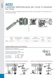
Selection positioningrange Y and U:0...10 V / 0…20 mA or2...10 V / 4...20 mAURi > 500 ΩONOFF0...10 V 2...10 VONOFFOutput signal U (position feedback signal) isdependent on the load resistance Ri.Ri > 500 Ω, voltage signalRi < 500 Ω, current signalRi < 500 Ω0...20 mA 4...20 mA4461Z23Selection valvecharacteristicsEqual-percentage orlinearV .ONOFFV .ONOFFYY4461Z24Forced <strong>control</strong> input ZZ - functionno function fully open closedTransferFunctionConnections• Z is not connected• The valve will follow the Y-signal or phase-cut signal• Z connected to G• The valve will fully openvia <strong>control</strong> path A AB• Z connected to G0• The valve will close via <strong>control</strong>path A ABSignal priorityCalibration1. Hand wheel position Man (open) or Off2. Forced <strong>control</strong> signal Z3. Phase-cut signal Phs4. Signal input YIf the electronics module is replaced or the <strong>actuator</strong> turned through 180 °, the valve’selectronics must be recalibrated. For that, the hand wheel must be set to Auto.The printed circuit board has a slot (position 3, preceding page).Calibration is made by bridging the contacts located behind the slot usinga screwdriver. The valve will then travel across the full stroke to store theend positions.01124While calibration is in progress, the green LED will flash for about 10 seconds (also referto «Indication of operating state»).4/14Siemens <strong>Modulating</strong> <strong>control</strong> <strong>valves</strong> <strong>with</strong> <strong>magnetic</strong> <strong>actuator</strong>, <strong>PN</strong> 16 CE1N<strong>4361</strong>enBuilding Technologies 08.06.2010
Indication ofoperating stateLED Indication Function Remarks, troubleshootingGreen Lit Control mode Normal operation; everything o.k.FlashingCalibrationIn manual <strong>control</strong>Red Lit Calibration errorInternal errorFlashingMains faultDC Supply - / +Both Dark No power supplyElectronics faultyWait until calibration is finished(green or red LED will be lit)Hand wheel in Man or Off positionRecalibrate (bridge contacts behind the calibrationslot)Replace electronics moduleCheck mains network (outside the frequency orvoltage range)DC supply + / - connection rectifyCheck mains network, check wiringReplace electronics moduleDimensionWorking pressure andmedium temperatureFluidsWorking pressure [bar]16151413121012080100120 140 160180 200Medium temperature [°C]Current local legislation must be observed.Saturated steamSuperheated steamAbsolute working pressure [bar]Medium temperature [°C]wet steamsaturated steamsuperheated steamavoidpermissible range of useSiemens <strong>Modulating</strong> <strong>control</strong> <strong>valves</strong> <strong>with</strong> <strong>magnetic</strong> <strong>actuator</strong>, <strong>PN</strong> 16 CE1N<strong>4361</strong>enBuilding Technologies 08.06.20105/14
Water flow chartMVF461H...V 100V 100p v100Δp V100 = differential pressure across the fully open valve and the valve’s <strong>control</strong> path A → AB by avolume flow V100V100 = volume flow through the fully open valve (H 100 )Δpmax = max. permissible differential pressure across the valve’s <strong>control</strong> path for the entire actuatingrange of the motorized valve100 kPa = 1 bar ≈ 10 mWC1 m 3 /h = 0,278 l/s water at 20 °CValve characteristicEqual-percentageVolumetric flow[%]LinearVolumetric flow[%]1009006310090064808060604040202000246810 [V]00246810 [V]2610 [V]2610 [V]41220 [mA]Positioning signals412Positioning signals20 [mA]7/14Siemens <strong>Modulating</strong> <strong>control</strong> <strong>valves</strong> <strong>with</strong> <strong>magnetic</strong> <strong>actuator</strong>, <strong>PN</strong> 16 CE1N<strong>4361</strong>enBuilding Technologies 08.06.2010
Connection type 1)4-wire connectionThe 4-wire connection should always be given preference!S NA P MED S TR I F Wire cross-section [mm 2 ]1,5 2,5 4,0Type reference [VA] [W] [VA] [A] max. cable length L [m]MVF461H15-0.6MVF461H15-1.5MVF461H15-3MVF461H20-5MVF461H25-833 15 50 3.15 60 100 160MVF461H32-12 43 4 40 70 12020 75MVF461H40-20656.3 30 50 80MVF461H50-3026 100S NAP medS TRI NL= nominal apparent power for selecting the transformer= typical power consumption= Minimal require transformer power= required slow fuse= max. cable length; <strong>with</strong> 4-wire connections, the max. permissible length of the separate1.5 mm 2 copper positioning signal wire is 200 m1)All information at AC 24 VMounting notesThe valve is supplied complete <strong>with</strong> Mounting Instructions 74 319 0378 0.CautionThe valve may only be used in flow direction (A AB).Observe the direction of flow!Mounting position90°IP3190°IP314461Z16Installation notes• The <strong>actuator</strong> may not be laggedFor electrical installation, refer to «Connection diagrams».Maintenance notesRepairThe low friction and robust, maintenance-free design makes regular servicingunnecessary and ensure a long service life.The valve stem is sealed from external influences by a maintenance-free gland.If the red LED is lit, the electronics must be recalibrated or replaced.Should the valve electronics prove faulty, the ASE12 electronics module must bereplaced (refer to Mounting Instructions 74 319 0404 0).CautionAlways disconnect power before fitting or removing the electronics module.After replacing the electronics module, calibration must be triggered in order tooptimally match the electronics to the valve (refer to «Calibration»).Disposal notesThe <strong>actuator</strong> contains electric and electronic components and may not be disposed oftogether <strong>with</strong> household waste.Local and currently valid legislation must be observed.8/14Siemens <strong>Modulating</strong> <strong>control</strong> <strong>valves</strong> <strong>with</strong> <strong>magnetic</strong> <strong>actuator</strong>, <strong>PN</strong> 16 CE1N<strong>4361</strong>enBuilding Technologies 08.06.2010
WarrantyApplication-specific technical data must be observed.If specified limits are not observed, Siemens Switzerland Ltd / HVAC Productswill not assume any responsibility.Technical dataFunctional data of <strong>actuator</strong>Power supplyFor use <strong>with</strong> low-voltage only (SELV, PELV)AC 24 V Operating voltage AC 24 V +20 / -15 %Frequency45...65 HzTypical power consumption P med refer to «Connection type», page 8Standby < 1 W (valve fully closed)Rated apparent power S NA refer to «Connection type», page 8Required fuse I F slow, «Connection type», page 8DC 24 V Operating voltageDC 20...30 VSignal inputs Control signal Y DC 0/2...10 Vor DC 0/4...20 mAor phase cut signal DC 0...20 V PhsImpedance DC 0/2...10 V 100 kΩ // 5nF (load < 0.1 mA)DC 0/4...20 mA240 Ω // 5nFForced <strong>control</strong> ZImpedance22 kΩClosing the valve (Z connected to G0) < AC 1 V; < DC 0.8 VOpening the valve (Z connected to G) > AC 6 V; > DC 5 VNo function (Z not wired up)phase-cut or <strong>control</strong> signal Y activeSignal outputs Position feedback signal voltage DC 0/2...10 V; load resistance > 500 ΩcurrentDC 0/4...20 mA; load resistance ≤ 500 ΩStroke measurementNonlinearityinductive± 3 % of end valuePositioning time Positioning time < 2 sElectrical connections Cable entries 2 x ∅ 20,5 mm (for M20)Connection terminalsscrew terminals for 4 mm 2 wiresMin. wire cross-section 0.75 mm 2Max. cable length refer to «Connection type», page 8Functional data of valve Pressure class <strong>PN</strong>16 to EN 1333Permissible operating pressure 1) <strong>with</strong>in the permissible "medium temperature"range according to the diagram on page 5Water up to 120 °C: 1.6 MPa (16 bar)Water above 120 °C: 1.3 MPa (13 bar)Saturated steam: 0.9 MPa (9 bar)Differential pressure Δpmax / Δp S 1 MPa (10 bar)Leakage rate at Δp = 0.1 MPa (1 bar) A → AB max. 0.05 % k VSValve characteristic 2) equal percentage, n gl = 3 to VDI / VDE 2173or linear, optimized near the closing pointPermissible mediaWaterSteamchilled water, low temperature hot water, hightemperature hot water, water <strong>with</strong>anti-freeze; recommendation: watertreatment to VDE 2035Saturated steam, superheated steamdryness at inlet minimum 0.98Medium temperature >1...180 °CStroke resolution ΔH / H 1001 : 1000 (H = stoke)Position when <strong>actuator</strong> is deenergized A → AB closedSiemens <strong>Modulating</strong> <strong>control</strong> <strong>valves</strong> <strong>with</strong> <strong>magnetic</strong> <strong>actuator</strong>, <strong>PN</strong> 16 CE1N<strong>4361</strong>enBuilding Technologies 08.06.20109/14
Mounting positionupright to horizontalControl modemodulatingMaterials Valve body modular cast iron EN-GJS-400-18-LTCovering flangemodular cast iron EN-GJS-400-18-LTSeat / plugCrNi-steelValve stem sealEPDM (O-ring)Weight and dimensions Dimensions refer to «Dimensions»Weightrefer to «Dimensions»Norms and standards CE conformityto EMV-requirements2004/108/ECImmunity EN 61000-6-2:[2005] Industrial 3)Emission EN 61000-6-3:[2007] ResidentialElectrical safety EN 60730-1Housing protectionUpright to horizontal IP31 to EN 60529Vibration 4) EN 6060068-2-6(1 g acceleration, 1...100 Hz, 10 min)Conform to UL standardsCSA, CanadaC-tickEnvironmental compatibilityUL 873C22.2 No. 24N 474ISO 14001 (Environment)ISO 9001 (Quality)SN 36350 (Environmentally compatibleproducts)RL 2002/95/EC (RoHS)Pressure Equipment Directive PED 97/23/ECPressure accessories as per article 1, section 2.1.4Fluid group 2 <strong>with</strong>out CE-marking as per article 3, section 3(sound engineering practice)Tested at 1.5 x <strong>PN</strong> (24 bar), similar to EN 12266-1Can be selected via DIL switchTransformer 160 VA (e.g. Siemens 4AM 3842-4TN00-0EA0)In case of strong vibrations, use high-flex stranded wires for safety reasons.1)2)3)4)General environmentalconditionsOperationEN 60721-3-3TransportEN 60721-3-2StorageEN 60721-3-1Climatic conditions Class 3K5 Class 2K3 Class 1K3Temperature -5...+45 °C -25...+70 °C -5...+45 °CHumidity 5...95 % r.h. 5...95 % r.h. 5...95 % r.h.Mechanical conditions EN 60721-3-6Class 3M2Connection terminalsSystem neutral AC 24 V, DC 20…30 VSystem potential AC 24 V, DC 20…30 VControl signal DC 0/2…10 V, DC 0/4…20 mAMeasuring neutral (= G0)Position feedback signal DC 0/2…10 V, DC 0/4…20 mAForced- <strong>control</strong> input ZPhase-cut signal DC 0...20 V Phs, interchangeable, galvanically isolatedPhase-cut signal DC 0...20 V Phs, interchangeable, galvanically isolated10/14Siemens <strong>Modulating</strong> <strong>control</strong> <strong>valves</strong> <strong>with</strong> <strong>magnetic</strong> <strong>actuator</strong>, <strong>PN</strong> 16 CE1N<strong>4361</strong>enBuilding Technologies 08.06.2010
Connection diagramsCautionCautionIf <strong>control</strong>ler and valve receive their power from separate sources, only onetransformer may be earthed on the secondary side.In case of DC power supply, a 4-wire connection is mandatory!Terminal assignmentfor <strong>control</strong>ler <strong>with</strong>4-wire connection(to be preferred!).DC 0...10 VDC 2...10 VDC 0...20 mADC 4...20 mACommon TransformerSeparate TransformerTerminal assignmentfor <strong>control</strong>ler <strong>with</strong>3-wire connectionDC 0...10 VDC 2...10 VDC 0...20 mADC 4...20 mACommon TransformerSeparate TransformerU Indication of valve position (only if required). DC 0 ...10 V → 0...100 % volumetric flow V 100Twisted pairs. If the lines for AC 24 V power supply and the DC 0...10 V (DC 2...10 V,DC 4... 20 mA) positioning signal are routed separately, the AC 24 V line need not be twisted.WarningPiping must be connected to potential earth!Controllers <strong>with</strong>phase-cutDC 0...20 V PhsCommon TransformerSeparate TransformerSiemens <strong>Modulating</strong> <strong>control</strong> <strong>valves</strong> <strong>with</strong> <strong>magnetic</strong> <strong>actuator</strong>, <strong>PN</strong> 16 CE1N<strong>4361</strong>enBuilding Technologies 08.06.201011/14
Application examplesThe examples shown below are basic diagrams <strong>with</strong> no installation-specific details.9H808 A9H807 ADistrict heating (supply heating) system,indirect connection.District heating (supply heating) system,directly connected to water-heating systemCautionThe valve may only be used in flow direction (A AB). The direction of flowmust be observed!DimensionsFlange dimensions to DIN2533, <strong>PN</strong>16Type reference DN L ø D ø D2 B ø K H ø E F Weight[mm] [mm] [mm] [mm] [mm] [mm] [mm] [mm] [kg]MVF461H15-0.6 15 130 95 4x14 14 65 340 80 115 8,3MVF461H15-1.5 15 130 95 4x14 14 65 340 80 115 8,3MVF461H15-3 15 130 95 4x14 14 65 340 80 115 8,3MVF461H20-5 20 150 105 4x14 16 75 339 80 115 8,9MVF461H25-8 25 160 115 4x14 16 85 346 80 115 10,0MVF461H32-12 32 180 140 4x18 18 100 384 100 125 15,7MVF461H40-20 40 200 150 4x18 18 110 401 100 125 17,8MVF461H50-30 50 230 165 4x18 20 125 449 125 138 27,2Weight incl. packaging12/14Siemens <strong>Modulating</strong> <strong>control</strong> <strong>valves</strong> <strong>with</strong> <strong>magnetic</strong> <strong>actuator</strong>, <strong>PN</strong> 16 CE1N<strong>4361</strong>enBuilding Technologies 08.06.2010
Revision numbersType referenceMVF461H15-0.6MVF461H15-1.5MVF461H15-3MVF461H20-5MVF461H25-8MVF461H32-12MVF461H40-20MVF461H50-30..C..C..C..B..B..B..C..BValid from rev. No.Siemens <strong>Modulating</strong> <strong>control</strong> <strong>valves</strong> <strong>with</strong> <strong>magnetic</strong> <strong>actuator</strong>, <strong>PN</strong> 16 CE1N<strong>4361</strong>enBuilding Technologies 08.06.201013/14
14/14 2010 Siemens Switzerland LtdSubject to changeSiemens <strong>Modulating</strong> <strong>control</strong> <strong>valves</strong> <strong>with</strong> <strong>magnetic</strong> <strong>actuator</strong>, <strong>PN</strong> 16 CE1N<strong>4361</strong>enBuilding Technologies 08.06.2010