Product Specification - Gentex Corporation
Product Specification - Gentex Corporation
Product Specification - Gentex Corporation
- No tags were found...

You also want an ePaper? Increase the reach of your titles
YUMPU automatically turns print PDFs into web optimized ePapers that Google loves.
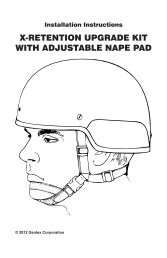
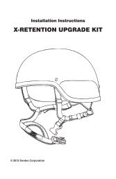
Installation InstructionsANVIS NVG BRACKET KITPart Numbers C12036-2 through C12036-4© 2013 <strong>Gentex</strong> <strong>Corporation</strong>
When you replace components or install additional components on<strong>Gentex</strong> products, always use genuine factory-new <strong>Gentex</strong> parts. Thiswill ensure a correct fit and maintain the safety of the product. Useof non-<strong>Gentex</strong> parts (salvage, refurbished, etc.) for replacementor additional installation will void any product warranty and maycompromise the safety of the user.
ContentsOVERVIEW................................................................................ 1INSTALLATION......................................................................... 2Tools and Materials Required...................................................... 2Attaching the Mounting Bracket to the Helmet.......................... 2Attaching the NVG Housing Base to the Mounting Bracket....... 3Attaching the Pile Fasteners to the Helmet............................... 4PARTS LIST.............................................................................. 5APPENDIX: Using Optional Attachment Strap....................... 6
Attaching the NVG Housing Base to the Mounting BracketReferring to Figure 3, do the following:1. Align the four small holes in the NVG housing base over the four small holesin the mounting bracket.NOTE: Before you insert the screws (Step 2), apply thread-locking adhesiveto the threads of each screw.2. Insert the four cross-recessed screws into the NVG housing base and intothe mounting bracket.3. Tighten the screws.NOTE: After you have completed these steps, you can modify and installyour ANVIS mount to the NVG housing base. The inset in Figure 3 showsa typical ANVIS mount modification. See the applicable ANVIS mountmodification kit instruction booklet for more information.NVG housing baseMounting bracketCross-recessed screwsLocating pinsHook fastener(wrapped aroundcable connector)ANVIS mount(customerfurnished)Backing plateCable clampNutTypical ANVIS mount modification(components not includedin bracket kit)Figure 3. Attachment of NVG Housing Base3
Attaching the Pile Fasteners to the HelmetReferring to Figure 4, attach the two pile fasteners to the center back of thehelmet. Press firmly. (The pile fasteners hold the NVG power pack.)NOTE: If the pile fasteners do not adhere properly to the helmet (whichsometimes occurs on rough-textured surfaces), apply additional adhesive(3M 847 or equivalent) to the adhesive side of the pile fasteners.Pile fasteners4Figure 4. Attachment of Pile Fasteners
PARTS LISTBelow is a parts list for the bracket kit. For more information, contact:<strong>Gentex</strong> <strong>Corporation</strong> Phone: (570)282-3550324 N. Main St. Fax: (570)282-8555Simpson, PA 18407www.gentexcorp.comANVIS NVG Bracket Kit, Part Numbers C12036-2 through C12036-4 (Figure 5)ANVIS NVG Bracket KitC12036-2(V50 2150 helmets,.320-.350 in. thick)NVG Housing BaseC12036-20 1 ea.Mounting BracketB12035-1 1 ea.Cross-recessed ScrewsA8241-1 4 ea.Slotted ScrewA5049-4 1 ea.T-nutA2104-4 1 ea.Pile FastenersB7951-1 2 ea.Instruction BookletTP0279 1 ea.ANVIS NVG Bracket KitC12036-3(V50 1400 helmets,.170-.190 in. thick)NVG Housing BaseC12036-20 1 ea.Mounting BracketB12035-3 1 ea.Cross-recessed ScrewsA8241-1 4 ea.Slotted ScrewA3093-13 1 ea.T-nutA2104-3 1 ea.Pile FastenersB7951-1 2 ea.Instruction BookletTP0279 1 ea.ANVIS NVG Bracket KitC12036-4(non-ballistic helmets,.110-.130 in. thick)NVG Housing BaseC12036-20 1 ea.Mounting BracketB12035-2 1 ea.Cross-recessed ScrewsA8241-1 4 ea.Slotted ScrewA3093-9 1 ea.T-nutA2104-2 1 ea.Pile FastenerB7951-1 2 ea.Instruction BookletTP0279 1 ea.NVG housing baseMounting bracketCross-recessed screwsT-nutPile fastenersSlotted screwFigure 5. ANVIS NVG Bracket KitTBH II is a trademark of <strong>Gentex</strong> <strong>Corporation</strong>.Loctite ® is a registered trademark of Loctite <strong>Corporation</strong>.5
APPENDIX: Using Optional Attachment StrapAn optional attachment strap (Figure 6) is available for use with the ANVISNVG bracket kit. This strap attaches the bracket to the helmet with a simpleadjustment and permits the bracket to be used over a fabric helmet cover.Figure 6. NVG Attachment Strap, Part Number B11737-5To use the attachment strap, follow these steps:1. Attach the NVG housing base to the bracket with four screws (Figure 7,View A).2. Insert the end of the attachment strap through the grommet slot at the topof the NVG housing base and then through the slide adjustment (Figure 7,View B).View AAttaching NVG housing base to bracketHousing baseBracketHousing baseand bracket assembledView BAttaching strap to NVG housing base6Figure 7. Assembling Housing Base, Bracket, and Strap
3. Attach the assembly to the helmet as follows:a. Place the front clips under the center front edge of the helmet (Figure 8).Ensure that the clips are centered. Position the strap rearward.(Continued on next page)StrapFrontclipsFigure 8. Attaching Bracket and Strap to Helmet (Front)7
. Press the adjustment mechanism and pull the ratchet strap toward therear of the helmet to loosen the strap (Figure 9).c. Lift the locking mechanism up.d. Place the rear clip under the center rear edge of the helmet. Ensure thatthe clip is properly centered.(Continued on next page)Adjustment mechanism(press)Ratchet strap(pull toward rear)Locking mechanism(lift up)Rear clip(place under center rear edge)Figure 9. Loosening Strap (Rear)8
e. Press the adjustment mechanism and pull the ratchet strap toward thefront of the helmet as far as possible to tighten the strap (Figure 10).f. Press the locking mechanism down to lock it into place.g. Ensure that the strap is tightly secured so that it does not move on thehelmet. If the strap is not tight enough, lift the locking mechanism, tightenthe front webbing strap (moving the slide adjustment forward or back asneeded), and redo Steps a-f as necessary.Adjustment mechanism(press)Slide adjustment(move forward or back as needed)Front webbing strapRatchet strap(pull toward front)Locking mechanism(press down)Figure 10. Tightening Strap (Rear)9
NOTES
TP0279 REV. 3 JANUARY 2013