Trane Engineers Newsletter, volume 32-2
Trane Engineers Newsletter, volume 32-2
Trane Engineers Newsletter, volume 32-2
- No tags were found...

Create successful ePaper yourself
Turn your PDF publications into a flip-book with our unique Google optimized e-Paper software.
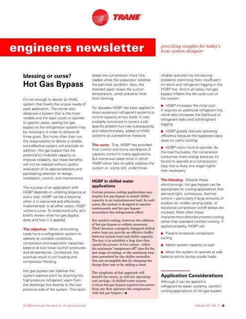
engineers newsletterproviding insights for today’shvac system designerblessing or curse?Hot Gas BypassIt’s not enough to deliver an HVACsystem that meets the unique needs ofeach application. The owner alsodeserves a system that is the mostreliable and the least costly to operate.In specific cases, adding hot gasbypass to the refrigeration system maybe necessary in order to achieve allthree goals. But more often than not,the responsibility to deliver a reliable,cost-effective system will preclude itsaddition. Hot gas bypass has thepotential to modulate capacity orimprove reliability, but these benefitswill not be realized without carefulevaluation of its appropriateness andpainstaking attention to design,installation, control, and maintenance.The success of an application withHGBP depends on unfailing diligence atevery step. HGBP can be a blessingwhen it is warranted and effectivelyimplemented. In all other cases, HGBPwill be a curse. To understand why, let’sbriefly review what hot gas bypassdoes and how it is applied.The objective. When diminishingloads force a refrigeration system tooperate at unstable conditions,compressor and evaporator capacitiesbalance at ever lower suction pressuresand temperatures. Unchecked, theeventual result is coil frosting andcompressor flooding.Hot gas bypass can stabilize thesystem balance point by diverting hot,high-pressure refrigerant vapor fromthe discharge line directly to the lowpressureside of the system. This tactickeeps the compressor more fullyloaded while the evaporator satisfiesthe part-load condition. Also, thediverted vapor raises the suctiontemperature, which prevents frostfrom forming.For decades HGBP has been applied indirect-expansion refrigerant systems tocontrol capacity at low loads. It wasprobably conceived to correct a jobspecificproblem but was subsequently,and indiscriminately, added to HVACsystems as a preventive measure.The curse. True, HGBP has providedfrost control and some semblance ofcapacity control in many applications.But numerous cases exist in whichHGBP either fails to safely stabilize thesystem or, worse still, underminesHGBP in chilled waterapplicationsCertain process cooling applications mayrequire hot gas bypass to match chillercapacity to an instantaneous load. In suchcases, the system is designed to operatecontinuously and hot gas bypassneutralizes the refrigeration effect.For comfort cooling, however, the additionof hot gas bypass is seldom necessary.That’s because a properly designed chilledwater loop can provide an effective bufferbetween system load and chiller capacity.The key is to establish a loop time thatequals the greater of two values: eitherthe minimum “compressor off” time for thelast stage of cooling, or the minimum looptime permitted by the chiller controller.You can accomplish this by changing thedesign flow rate or by adding a tank.The simplicity of this approach willbenefit the owner, as will the operatingcostsavings. (A chilled water systemwithout hot gas bypass requires less powerthan one that operates the compressorswith hot gas bypass.) ■reliable operation by introducingproblems stemming from insufficientoil return and refrigerant logging in theHGBP line. And in all cases, hot gasbypass inflates the life-cycle cost ofthe system:■ HGBP increases the initial cost.It requires an additional refrigerant line,which also increases the likelihood ofrefrigerant leaks and oil/refrigerantlogging.■ HGBP greatly reduces operatingefficiency because the bypassed vapordoes no useful cooling.■ HGBP costs more to operate. Asthe load fluctuates, the compressorconsumes more energy because it’sforced to operate at a compressionstep that is likely one stage higherthan necessary.The blessing. Despite theseshortcomings, hot gas bypass can beappropriate for cooling applications thatdemand tight, continuous, thermalcontrol—particularly if large amounts ofoutdoor air, widely varying loads, orexcessive compressor on/off delays areinvolved. Most often thesecharacteristics describe process coolingrather than standard comfort cooling. Ifapplied properly, HGBP can:■ Prevent excessive compressorcycling■Match system capacity to load■ Allow the system to operate at safebalance points during unsafe loadsApplication ConsiderationsAlthough it can be applied inrefrigerant-to-water systems, comfortcooling applications of hot gas bypass© 2003 American Standard Inc. All rights reserved Volume <strong>32</strong>, No. 2 ■
most often involve refrigerant-to-airevaporators. With countlesscombinations of equipment and layoutspossible, how can you best and mostresponsibly implement hot gas bypass?Figure 1. Hot gas bypassed to evaporator inlet (preferred arrangement for HGBP)Apply HGBP as a last resort. Onlyuse hot gas bypass if all other designoptions fail to meet the demands of theapplication. To make this determination,it is critical to …Understand the year-round loadsand requirements of the system.“Most comfort cooling applicationscan operate between steps of loadingwithout loss of temperature or humiditycontrol.” Not only does this statementhold true between the third and fourthsteps of cooling, when the outdoorlatent load is high, but it also holds truefor the step between off and first-stagecooling when the outdoor latent loadis comparatively low.Choose the right arrangement. Hotgas bypass is arranged in one of twoways (see the comparison in Table 1,p. 4); both require special care duringdesign and installation. 1 HGBP to theevaporator inlet delivers hot refrigerantvapor between the expansion valve andthe distributor (Figure 1). During HGBPoperation, the expansion valve metersenough liquid refrigerant to bothdesuperheat the bypassed vapor andsatisfy the evaporator load. Theresulting refrigerant flow rate issufficient to carry oil through the coiland suction line.HGBP to the suction line bypassesboth the condenser and the evaporator,diverting hot vapor from thecompressor discharge directly to thesuction line (Figure 2). A liquid-injectionvalve meters liquid refrigerant into thestream of bypassed vapor, cooling it1 For more information, see Hot Gas BypassControl (<strong>Trane</strong> publication AM-CON10) and the1998 ASHRAE Handbook–Refrigeration.Keys to successful implementation:1 Position the HGBP valve above the dischargeline, near the compressor. If the systemincludes pump-down, provide a means to shutoff refrigerant flow.2 Pitch the line upstream of the HGBP valve todrain oil back into the discharge line.3 Pitch the line downstream of the HGBP valvetoward the evaporator, away from the valve.4 If the HGBP line includes a riser, regardless ofheight, provide a drain leg of the sameenough to prevent the compressormotor from overheating.Do not oversize the system. Anoversized system quickly meets thesensible load without satisfying thelatent load. Adding HGBP may mitigatethis error … but at the expense ofunnecessarily high power bills.Once again, understanding the yearroundloads and properly sizing thesystem to match them is paramount toproviding thermal comfort (controllingtemperature and humidity) andeliminating the need for HGBP.Select equipment with multiple-steprefrigerant circuits. The logic foravoiding system oversizing alsosupports the choice of multiple-steprefrigerant circuit(s) whenever possible.The capacity of an unloading refrigerantcircuit will attempt to match a reducedload at better balance points.diameter as the riser. Add an oil-return line1 in. (25 mm) from the bottom of the trap; usetubing that is 1/8 in. (6 mm) and at least 5 ft(300 mm) long. Precharge the trap with oil.5 Divert hot gas to each active distributor at theexpected operating points for hot gas bypass.6 If the HGBP line feeds multiple distributors,provide a check valve for each distributor.7 Insulate the entire length of the HGBP line.Select an evaporator coil thatcan maintain a high suctiontemperature to permit the system toaggressively stage down before a frostcondition develops. In all cases, thedesign should maximize the suctiontemperature while maintaining thedesired conditions. For comfort coolingapplications, the minimum saturatedsuction temperature at design shouldbe 43°F to 45°F for variable-<strong>volume</strong> airdistribution (VAV), or 40°F to 43°F forconstant-<strong>volume</strong> air distribution (CV).Coils with intertwined circuits tend toreduce the risk of coil frosting becausethey use more of the available finsurface (than face-split coils) at partloadconditions. This allows the systemto operate at higher suctions and morereliable balance points.■ 2 <strong>Trane</strong> <strong>Engineers</strong> <strong>Newsletter</strong> — Vol. <strong>32</strong>, No. 2
Figure 2. Hot gas bypassed to suction lineKeys to successful implementation:1 Position the HGBP valve above the dischargeline, near the compressor. If the systemincludes pump-down, provide a means to shutoff refrigerant flow.2 Pitch the line upstream of the HGBP valve todrain oil back into the discharge line.3 Pitch the line downstream of the HGBP valvetoward the suction line, away from the valve.4 Assure that the evaporator and suction linefreely drain to the suction-line HGBPconnection.Target the cooler, drier part of thethermal comfort envelope.Compressor cycling usually isn’t anissue for comfort-cooling VAV or CVapplications. But this strategy providesmore latitude for the space condition to“float” during compressor stagingwithout sacrificing thermal comfort.Comply with local codes. ASHRAE/IESNA Standard 90.1, Energy Standardfor Buildings Except Low-RiseResidential Buildings, precludes theuse of hot gas bypass for HVACsystems larger than 7.5 tons unlessthey are designed with multiple stepsof unloading or continuous capacitymodulation. The maximum amount ofHGBP allowed by the standard varieswith system size: 25 percent of totalcapacity for systems larger than20 tons, 50 percent for systemsranging from 7.5 to 20 tons. 25 Site the suction-line HGBP connectionupstream of the pilot-line tap for the HGBPvalve and at least 5 ft (1.5 m) upstream from thecompressor inlet. Angle the connection into thesuction flow.6 Attach the remote bulb for the liquid-injectionvalve to the suction line, downstream of theHGBP connection.7 Provide a solenoid valve upstream of the liquidinjectionvalve. Synchronize the operation of theHGBP and liquid-line solenoid valves.8 Insulate the entire length of the HGBP line.Line Design ConsiderationsMake gravity work for you. A typicalHGBP valve can infinitely vary the rateof hot gas flow. The resultingrefrigerant velocity can become so lowthat it “traps” oil in the HGBP line.Gravity then becomes the sole meansfor returning oil to the compressor. It istherefore critical to design therefrigerant piping system so that all oil(and condensed refrigerant) drainsfreely out of the HGBP line.Suction-line lift and the design of theevaporator coil particularly limit the useof HGBP to the suction-line. Because2 Standard 90.1 (which excludes processapplications and low-rise residential buildings)grants an exception to systems smaller than7.5 tons. Be sure to consult the standard forspecific requirements.this arrangement bypasses theevaporator and part of the suction line,the refrigerant flow rate upstream ofthe HGBP point of entry may becometoo low to move oil. To overcome thislimitation, restrict the maximumamount of HGBP to a quantity thatmaintains sufficient refrigerant velocityfor oil entrainment.Note: If this design cannot beaccomplished, it is critical to assurethat oil drains freely from both theevaporator and the suction line to theinlet of the HGBP line. Failure to do sowill starve the compressor of oil andshorten the life of the compressor.Independent of which HGBParrangement is applied, the HGBP linemust connect to the top of both thedischarge line and the evaporator inlet(or suction line). Otherwise, a mixtureof oil and refrigerant will pour into theHGBP line, starving the compressor ofoil and causing a liquid slug when theHGBP valve opens.The refrigerant that collects in theHGBP line also reduces the refrigerantcharge available to the system, whichmay lower the suction pressure.Ironically, the HGBP valve may respondby opening and allowing bypass flow ofhot gas. The repetitive, unstableoperation and slugging that result makeit critical to prevent this condition.Select the appropriate pipediameter. With HGBP lines, typicallysmaller is better to promote oilmovement; however, a design thatallows gravity to purge any liquid fromthe HGBP line lessens thisrequirement. Size the line for apressure drop of 6 psid to 20 psid.Keep the HGBP line short.Refrigerant vapor will condense in, andfill any portion of, the HGBP line that iscolder than the saturated temperatureof the suction or discharge gas.Incidences (and consequences) of“providing insights for today’s HVAC system designer”3 ■
efrigerant condensation will increasewith the length of the line, despiteinsulation.Oil return also can be a problem inproperly designed HGBP lines becausethe HGBP valve can reduce the flow ofbypassed gas to nearly zero—wellbelow the minimum flow rate neededto carry oil back to the compressor.Gravity will be very slow to bring the oilthat deposits along the length of theHGBP line back to the compressor. Thelonger the HGBP line, the more oil itwill collect. It is imperative to keep theoil charge in the system, not in theHGBP line.Select an appropriate HGBP valve.There are two basic types of HGBPvalves: proportional and electronic. Aproportional, pressure-actuated HGBPvalve opens a set amount based on thedifference between the valve’s suctionpressuresetpoint and the actualsuction pressure. Generally, valves ofthis type require a pressure differenceof 6 psig to open fully. Although thischaracteristic makes it difficult tomaintain a specific suction pressure, aproportional HGBP valve cansatisfactorily maintain a suctionpressurerange that is equivalent to± 4°F (saturated) suction temperature.By contrast, an electronic HGBP valvecan regulate bypass flow to maintainthe desired suction pressure ordischarge air temperature. If used inconjunction with a supply-airtemperaturecontrol, optimize systemefficiency by coordinating the operationof the HGBP valve and compressors.Note: If the refrigeration systemincludes pump-down, make sure thatthe HGBP system includes a means toprevent refrigerant flow during thepump-down cycle.Add head-pressure control. Divertinghot gas from the discharge line andaround the condenser reduces thehead pressure of the air conditioningsystem. As head pressure decreases,operation may become unstable — andunreliable. To avoid this risk, include amethod for head pressure control inevery HGBP application.A Final CaveatRisk of oil and refrigerant logging isinherent to hot gas bypass. Do notassume that adding hot gas bypass tothe job specification will improvereliability or enhance capacitymodulation. Neither benefit of HGBPwill be realized without meticulousattention to the desired effect,component selection, andimplementation. Anything less willTable 1. Comparison of common HGBP arrangementsEvaporator inlet (preferred; Figure 1, p. 2) Suction line (Figure 2, p. 3)Advantages■ Merging the bypassed load with the systemload in the evaporator helps the expansionvalve maintain superheat control■Sustains a higher gas velocity in theevaporator and suction line at low loads,enabling more reliable oil returnDisadvantages■ Installation cost is directly proportional to thedistance between the condensing unit andevaporatorcompromise system performance …and curse the owner with excessivemaintenance and power bills for yearsto come. That said, if HGBP bestaddresses the demands of a particularapplication then specify it. Ifimplemented responsibly, HGBP will bea blessing. ■By Paul Solberg, applications engineer,and Brenda Bradley, informationdesigner, <strong>Trane</strong>.You can find this and other issues ofthe <strong>Engineers</strong> <strong>Newsletter</strong> at http://www.trane.com/commercial/library/newsletters.asp.Advantages■ Less expensive to install because it requires lesspiping, particularly if the condensing unit andevaporator are far apartDisadvantages■ Requires an additional liquid-line solenoid valve andexpansion valve■At low evaporator loads, refrigerant-gas velocity maynot be sufficient for adequate oil movement■ Challenges the designer to slope the suction line intwo directions: toward the compressor during the oncycle, toward the evaporator during the off cycle<strong>Trane</strong>A business of American Standard Companieswww.trane.comFor more information, contact your local districtoffice or e-mail us at comfort@trane.com<strong>Trane</strong> believes the facts and suggestions presented here to be accurate. However,final design and application decisions are your responsibility. <strong>Trane</strong> disclaimsany responsibility for actions taken on the material presented.■ 4 ADM-APN007-EN