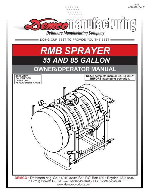
AS20009 - 55 & 85 Gallon RMB Sprayer ... - Demco Products
AS20009 - 55 & 85 Gallon RMB Sprayer ... - Demco Products
AS20009 - 55 & 85 Gallon RMB Sprayer ... - Demco Products
- No tags were found...
You also want an ePaper? Increase the reach of your titles
YUMPU automatically turns print PDFs into web optimized ePapers that Google loves.
PostageDethmers Manufacturing Company4010 320th Street, Box 189Boyden, Iowa 51234Page 4
SAFETY...YOU CAN LIVE WITH ITEQUIPMENT SAFETY GUIDELINESEvery year many accidents occur which could have been avoided by a few seconds ofthought and a more careful approach to handling equipment. You, the operator, can avoidmany accidents by observing the following precautions in this section. To avoid personalinjury, study the following precautions and insist those working with you, or you yourself,follow them.In order to provide a better view, certain illustrations in this manual may show an assemblywith a safety shield removed. However, equipment should never be operated in this condition.Keep all shields in place. If shield removal becomes necessary for repairs, replace shieldprior to use.Replace any caution, warning, danger or instruction safety decal that is not readable or ismissing. Location of such decals is indicated in this booklet.Do not attempt to operate this sprayer under the influence of alcohol or drugs.Review safety instructions with all users.Operator should be a responsible adult. DO NOT ALLOW PERSONS TO OPERATE ORASSEMBLE THIS UNIT UNTIL THEY HAVE DEVELOPED A THOROUGH UNDERSTANDINGOF SAFETY PRECAUTIONS AND HOW IT WORKS.To prevent injury or death, use a tractor equipped with a roll over protective system (ROPS).Do not paint over, remove, or deface any safety signs or warning decals on your sprayer.Observe all safety signs and practice instructions on them.Never exceed limits of a piece of machinery. If its ability to do a job, or to do so safely is inquestion-DON'T TRY IT.LIGHTING AND MARKINGIt is the responsibility of customer to know lighting and marking requirements of local highwayauthorities and to install and maintain sprayer to provide compliance with regulations. Addextra lights when transporting at night or during periods of limited visibility.Page 6
SAFETY SIGN LOCATIONSTypes of safety sign and locations on equipment are shown in illustration below. Good safetyrequires that you familiarize yourself with various safety signs, type of warning, and area orparticular function related to that area, that requires your SAFETY AWARENESS.ABA. AB21014 - Warning: Refer to chemicalsupplier and manufacturer Qty. 1WARNINGTo prevent serious injury or death• Refer to chemical supplier and manufacturer recommendations and alllicensing restrictions or regulations.• Always wear recommended protective clothing when working with chemicals orsprayer.• Dispose of all unused chemicals or solutions in proper and ecologicallysound manner. Improper use can injure people, animals, plants and soil.01/00 AB21014B. AA21012 - Small <strong>Demco</strong> Qty. 1Page 7
SAFETY SIGN CARE• Keep safety signs clean and legible at all times.• Replace safety signs that are missing or have become illegible.• Replacement parts that displayed a safety sign should also display current sign.• Safety signs are available from your distributor, dealer parts department, or factory.How to install safety signs:• Be sure that installation area is clean and dry.• Decide on exact position before you remove backing paper.• Remove smallest portion of split backing paper.• Align decal over specified area and carefully press small portion withexposed sticky backing in place.• Slowly peel back remaining paper and carefully smooth decal into place.• Air pockets can be pierced with a pin and smoothed out using piece of backing paper.BEFORE OPERATION:• Carefully study and understand this manual.• Do not wear loose-fitting clothing which may catch in moving parts.• Always wear protective clothing and substantial shoes.• It is recommended that suitable protective hearing and eye protection be worn.• The operator may come in contact with certain materials which may require specific safetyequipment relative to handling of such materials. (Examples: extremely dusty, molds,fungus, bulk fertilizers, etc.)• Give sprayer a visual inspection for any loose bolts, worn parts, or cracked welds, and makenecessary repairs. Follow maintenance safety instructions included in this manual.• Be sure there are no tools lying on or in equipment• Do not use sprayer until you are sure that area is clear, especially around children andanimals.• Don't hurry learning process or take sprayer for granted. Ease into it and become familiarwith your new equipment.• Practice operation of your equipment and its attachments. Completely familiarize yourselfand other operators with its operation before using.• Use a tractor equipped with Roll Over Protection System (ROPS) and fasten your seat beltprior to starting engine.• Manufacturer does not recommend usage of a tractor with ROPS removed.Page 8
• Move tractor wheels to widest recommended settings to increase stability.• Do not allow anyone to stand between tongue or hitch and towing vehicle whenbacking up to sprayer.DURING OPERATION• Beware of bystanders, PARTICULARLY CHILDREN! Always look around to make sure that itis safe to start engine of towing vehicle or move sprayer. This is particularly important withhigher noise levels and quiet cabs, as you may not hear people shouting.• NO PASSENGERS ALLOWED- Do not carry passengers anywhere on or in the tractor orsprayer.• Keep hands and clothing clear of moving parts.• Do not clean, lubricate, or adjust your sprayer while it is moving.• When halting operation, even periodically, set tractor or towing vehicles brakes, disengagePTO, shut off engine, and remove ignition key.• Be especially observant of operating area and terrain- watch for holes, rocks, or other hiddenhazards. Always inspect area prior to operation.- DO NOT operate near edge of drop-offs or banks.- DO NOT operate on steep slopes as overturn may result.- Operate up and down (not across) intermediate slopes. Avoid sudden starts and stops.• Pick the most level possible route when transporting across fields. Avoid edges of ditches,gullies, and steep hillsides.• Be extra careful when working on inclines.• Periodically clear sprayer of brush, twigs, or other materials to prevent buildup of drycombustible materials.• Maneuver tractor or towing vehicle at safe speeds.• Avoid overhead wires. Contact with overhead lines could cause serious injury or death.• Avoid loose gravel, rocks, and holes; they can be dangerous for sprayer operation or movement.• Allow for unit length when making turns.• Do not walk or work under raised components or attachments unless securely supported.• Keep all bystanders, pets, and livestock clear of work area.• Never stand alongside of unit with engine running or attempt to start engine and/or operatemachine while standing alongside of unit.• Never leave running equipment attachments unattended.• As a precaution, always recheck hardware on equipment following every 100 hours of operation.Correct all problems. Follow maintenance safety procedures.Page 9
FOLLOWING OPERATION• Following operation, or when unhitching, stop tractor or towing vehicle, set brakes,disengage PTO and all power drives, shut off engine and remove ignition key.• Store unit in an area away from human activity.• Do not park equipment where it will be exposed to livestock for long periods of time. Damage andlivestock injury could result.• Do not permit children to play on or around stored unit.• Make sure all parked machines are on a hard, level surface and engage all safety devices.HIGHWAY AND TRANSPORT OPERATIONS• SAFETY CHAINS: If equipment is going to be transported on a public highway, Alwaysfollow state and local regulations regarding safety chains and auxiliary lighting. Be sure tocheck with local law enforcement agencies for your own particular regulations. If requiredsafety chains should be obtained and installed. Only safety chains (not elastic or nylon/plastic tow straps) should be used to retain connection between towing and towed machines in event of separation of primary attaching system. Use a high strength, appropriately sized hitch pin with a mechanical retainer and attach safety chains. Criss crosschains under tongue and secure to draw bar cage, mounting loops, or bumper frame.• Adopt safe driving practices:- Keep brake pedals latched together at all times. NEVER USE INDEPENDENT BRAKINGWITH MACHINE IN TOW, LOSS OF CONTROL AND/OR UPSET OF UNIT CAN RESULT.- Always drive at a safe speed relative to local conditions and ensure that your speed is lowenough for an emergency stop. Keep speed to a minimum.- Reduce speed prior to turns to avoid risk of overturning.- Always keep tractor or towing vehicle in gear to provide engine braking when goingdownhill. Do not coast.- Do not drink and drive!• Comply with state and local laws governing highway safety and movement of farm machinery.• Use approved accessory lighting flags and necessary warning devices to protect operators ofother vehicles on highway during transport. Various safety lights and devices are availablefrom your dealer.• Use of flashing amber lights is acceptable in most localities. However, some localities prohibittheir use. Local laws should be checked for all highway lighting and marking requirements.• When driving a tractor and sprayer under 20 mph (40 kph) day or night, use flashing amber warninglights and a slow moving vehicle (SMV) identification emblem.• Plan your route to avoid heavy traffic.• Be a safe and courteous driver. Always yield to oncoming traffic in all situations, including narrowbridges, intersections, etc.• Be observant of bridge loading ratings. Do not cross bridges rated lower than gross weight atwhich you are operating.• Watch for obstructions overhead and side to side while transporting.• Always operate equipment in a position to provide maximum visibility at all times. Makeallowances for increased length and weight of sprayer when making turns, stopping, etc.Page 10
REMEMBERYour best assurance against accidents is a careful and responsible operator. If there is anyportion of this manual or function you do not understand, contact your local authorized dealeror manufacturer.PERFORMING MAINTENANCE• Good maintenance is your responsibility. Poor maintenance is an invitation to trouble.• Make sure there is plenty of ventilation. Never operate engine of towing vehicle in a closedbuilding. Exhaust fumes may cause asphyxiation.• Before working on this machine, stop towing vehicle, set brakes, disengage PTO and allpower drives, shut off engine and remove ignition key.• Be certain all moving parts and attachments have come to a complete stop beforeattempting to perform maintenance.• Always use a safety support and block wheels. Never use a jack to support machine.• Always use proper tools or equipment for job at hand.• Use extreme caution when making adjustments.• Follow torque chart on page 10 in this manual when tightening bolts and nuts.• Never use your hands to locate a hydraulic leak on attachments. Use a small piece ofcardboard or wood. Hydraulic fluid escaping under pressure can penetrate skin.• Openings in skin and minor cuts are susceptible to infection from hydraulic fluid.Without immediate medical treatment, serious infection and reactions can occur.• When disconnecting hydraulic lines, shut off hydraulic supply and relieve all hydraulicpressure.• Replace all shields and guards after servicing and before moving.• After servicing, be sure all tools, parts and service equipment are removed.• Do not allow grease or oil to build up on any step or platform.• When replacing bolts refer to owners manual.• Refer to bolt torque chart on page 12 for head identification marking.• Where replacement parts are necessary for periodic maintenance and servicing,genuine factory replacement parts must be used to restore your equipment to originalspecifications. Manufacturer will not claim responsibility for use of unapproved parts oraccessories and other damages as a result of their use.• If equipment has been altered in any way from original design, manufacturer doesnot accept any liability for injury or warranty.• A fire extinguisher and first aid kit should be kept readily accessible while performingmaintenance on this sprayer.Page 11
BOLT TORQUETORQUE DATA FOR STANDARD NUTS, BOLTS, AND CAPSCREWS.Tighten all bolts to torques specified in chart unless otherwise noted. Check tightness ofbolts periodically, using bolt chart as guide. Replace hardware with same grade bolt.NOTE: Unless otherwise specified, high-strength Grade 5 hex bolts are used throughoutassembly of equipment.Bolt Torque for Standard bolts *Torque SpecificationsGRADE 2 GRADE 5 GRADE 8“A” lb-ft (N.m) lb-ft (N.m) lb-ft (N.m)1/4” 6 (8) 9 (12) 12 (16)5/16” 10 (13) 18 (25) 25 (35)3/8” 20 (27) 30 (40) 45 (60)7/16” 30 (40) 50 (70) 80 (110)1/2” 45 (60) 75 (100) 115 (1<strong>55</strong>)9/16” 70 (95) 115 (1<strong>55</strong>) 165 (220)5/8” 95 (130) 150 (200) 225 (300)3/4” 165 (225) 290 (390) 400 (540)7/8” 170 (230) 420 (570) 650 (880)1” 225 (300) 630 (<strong>85</strong>0) 970 (1310)Bolt Torque for Metric bolts *Torque figures indicated are valid fornon-greased or non-oiled threads andheads unless otherwise specified.Therefore, do not grease or oil bolts orcapscrews unless otherwise specifiedin this manual. When using lockingelements, increase torque valuesby 5%.* GRADE or CLASS value for boltsand capscrews are identified by theirhead markings.CLASS 8.8 CLASS 9.8 CLASS 10.9“A” lb-ft (N.m) lb-ft (N.m) lb-ft (N.m)6 9 (13) 10 (14) 13 (17)7 15 (21) 18 (24) 21 (29)8 23 (31) 25 (34) 31 (42)10 45 (61) 50 (68) 61 (83)12 78 (106) 88 (118) 106 (144)14 125 (169) 140 (189) 170 (230)16 194 (263) 216 (293) 263 (357)18 268 (363) -- -- 364 (493)20 378 (513) -- -- 515 (689)22 516 (699) -- -- 702 (952)24 654 (886) -- -- 890 (1206)GRADE-2 GRADE-5 GRADE-8CLASS 8.8 CLASS 9.8 CLASS 10.98.8 9.8 10.9Page 12
ASSEMBLED <strong>55</strong> & <strong>85</strong> GALLON REAR MOUNT SPRAYERShown without tank.Page 13
<strong>55</strong> & <strong>85</strong> GALLON REAR MOUNT SPRAYER PARTS BREAKDOWN1413129323115 2725261116111120710112912221019241718181233630911101111288175417231731721243Page 14
<strong>55</strong> & <strong>85</strong> GALLON REAR MOUNT SPRAYER PARTS LISTREF. PARTNO. NO. QTY. DESCRIPTION1. 00004 4 5/16” Flatwasher2. 00059 2 3/8” Flatwasher3. 00095 2 3/8”-16 UNC x 3/4” Square Hd. Set Screw4. 00182 1 Hairpin (1/8")5. 00284-95 1 Three-Point Pin (Top)6. 00907 2 3/8”-16 UNC x 1” Hex Hd. Bolt7. 02128 2 3/8"-16 UNC x 3" Square U-bolt8. 02397 2 1/4" Quick Pin9. 02592 6 3/8”-16 UNC Nylon Insert Locknut10. 02772 8 1/4"-20 UNC Nylon Insert Locknut11. 02802 21 5/16”-18 UNC Nylon Insert Lock Nut12. 02990 3 5/16”-18 UNC x 1” Hex Hd. Bolt13. 04352 4 5/16”-18 UNC x 4” Hex Hd. Bolt (full thread)14. 04353 2 Strap ONLY (50” polyester strap)15. 04739 2 1" Square Cap Plug16. 04822 2 1/4"-20 UNC x 1 1/2" Square U-bolt17. 05677 7 5/16”-18 UNC x 1.625” Round U-Bolt18. 057<strong>55</strong> 4 3/4" Round Cap Plug19. 05756-70 1 Left Side Frame (<strong>55</strong> <strong>Gallon</strong>)- 05775-70 1 Left Side Frame (<strong>85</strong> <strong>Gallon</strong>)20. 05757-70 1 Right Side Frame (<strong>55</strong> <strong>Gallon</strong>)- 05776-70 1 Right Side Frame (<strong>85</strong> <strong>Gallon</strong>)21. 05760-70 2 Legs22. 05761-70 1 Top Crossmember23. 05762-95 1 Bottom Cross Shaft24. 05763-95 2 Lock Collar25. 05764-70 1 Left Boom Mount26. 05765-70 1 Right Boom Mount27. 05767-70 1 Control Valve Mount28. 05774-70 1 Bottom Shaft Brace29. 057<strong>85</strong>-95 4 “L” Bracket for Strap30. 05768-95 1 PTO Pump Storage Mount31. P<strong>55</strong> 23 1 <strong>55</strong> <strong>Gallon</strong> Tank for Electric Pump Only (includes Lid)- P<strong>85</strong> 24 1 <strong>85</strong> <strong>Gallon</strong> Tank for Electric Pump Only (includes Lid)- P<strong>55</strong> 23A 1 <strong>55</strong> <strong>Gallon</strong> Tank for Roller Pump Only (includes Lid)- P<strong>85</strong> 24A 1 <strong>85</strong> <strong>Gallon</strong> Tank for Roller Pump Only (includes Lid)32. PL5A 1 5" Lid33. 009<strong>55</strong> 2 1/4”-20 UNC x 1” Round U-boltPlease order replacement parts by PART NO. and DESCRIPTION.Page 15
SINGLE SECTION PLUMBING PARTS BREAKDOWN FOR <strong>55</strong> & <strong>85</strong> GALLONStrap Not IncludedSee pages 14-15 forStrap AssemblyBreakdown.516149NOTE: Use thread sealant on allthreaded fittings.15141218717131011143032681114 294123 2322 241310 26132332DC1431271322B281013132213212420201923abcA23*2526221013d13102221334136Page 162233353 376
SINGLE SECTION PLUMBING PARTS LISTREF. PARTNO. NO. QTY. DESCRIPTION1. 00214 5 1/4" Flatwasher*2. C6500 1 Hypro Roller Cast Iron Pump with out540/1000RPM Multi-Speed Quick Coupler*- XL6500 - Hypro Roller Silver Cast Pump with out540/1000RPM Multi-Speed Quick Coupler3. 02772 5 1/4"-20 UNC Nylon Insert Locknut4. 040<strong>55</strong> 4 1/4"-20 UNC x 1" Hex Head Bolt5. 0<strong>55</strong>95-70 1 Handgun Storage Bracket6. 1321 0012 1 Quick Coupler7. 120RB - 1/2" I.D. Rubber Hose8. 160GB 1 160 lb. Brass Pressure Gauge*9. 30L-18PP 1 15" Hand Spray Gun w/<strong>55</strong>00 Tip Included10. 340RB - 3/4" Rubber Hose11. 380RB - 3/8" I.D. Rubber Hose12. 5044 1 1 Single Agitation Wand Assembly13. B12H 10 3/4" Gear Clamp14. B6H 6 3/8" Gear Clamp15. BEL1212 1 1/2" MPT x 1/2" Hose Barb Elbow (GFP)16. A1438 1 1/4" MPT x 3/8" Hose Barb17. EL114 34 1 1-1/4" MPT x 3/4" Hose Barb Elbow18. M1200 1 1/2” MPT Nipple19. 0<strong>55</strong>96-95 1 Plumbing Hanger20. B20H 2 1-1/4” Gear Clamp21. BA3434 1 3/4” MPT x 3/4” Hose Barb (GFP)22. BEL3434 6 3/4” MPT x 3/4” Hose Barb Elbow (GFP)23. BM3400 5 3/4” MPT Nipple (GFP)24. BTT34 2 3/4” FPT Tee (GFP)25. RVF34 80 1 3/4" Line Strainer w/80 mesh screena. RVF34C 1 3/4" Strainer Capb. RVF380 1 80 Mesh Screen for 3/4" Strainerc. RVF34GV 1 Viton O-ring for 3/4" Strainerd. RVF34B 1 Strainer Bowl26. UV075FP 3 3/4” Poly Ball Valve*27. 6B1 1 Single Unit Valve*28. 8460 1 3/4" Pressure Relief Valve29. A1238 1 1/2" MPT x 3/8" Hose Barb30. A3438 1 3/4" MPT x 3/8" Hose Barb31. BEL3412 1 3/4" MPT x 1/2" Hose Barb Elbow (GFP)32. T34F 1 3/4” FPT Tee x 3/4”33. 00036 2 5/16” Lockwasher34. 01076 1 1/4”-20 UNC x 3/4” Hex Hd. Bolt35. 04298-70 1 Pump Mounting Bracket36. 04299 1 Roller Pump Chain and hook37. 04305 2 5/16”-18 UNC x 1/2” Hex Hd. Bolt (Gr.5)Please order replacement parts by PART NO. and DESCRIPTION.* denotes further breakdownOPERATING INSTRUCTIONS1. Fill the tank with water.2. Open the Ball valve (A) in the pumpintake line.3. Open (counter clockwise) thepressure relief valve (B).4. Open the Direct-o-valve (C).5. Open the agitation valve (D).7. Slowly close the pressure relief valve (B) until thedesired spraying pressure is reached with theboom spraying.8. If adequate spraying pressure cannot be reached,slowly close the agitation valve (D) until thedesired spraying pressure is reached.9. Check for leaks.6. Start and run pump.Page 17
THREE SECTION PLUMBING PARTS BREAKDOWN FOR <strong>55</strong> & <strong>85</strong> GALLON4171161311718221410127118213415449113115162826330C94429B11<strong>55</strong>32935 159D2110NOTE: Use thread sealant on allthreaded fittings.SAFETY STAND2045194737 3946482492316221022 151213843A15abcd2421*25331037 24403695•44423941Page 18
THREE SECTION PLUMBING PARTS LISTREF. PARTNO. NO. QTY. DESCRIPTION1. 1010RB - 1" I.D. Rubber Hose2. 120RB - 1/2" I.D. Rubber Hose3. 160GB 1 160 lb. Brass Pressure Gauge*4. 30L-18PP 1 15" Hand Spray Gun5. 340RB - 3/4" Rubber Hose6. 380RB - 3/8” Rubber Hose7. 5044 1 1 Single Agitation Wand Assembly8. A3438 1 3/4” MPT x 3/8” Hose Barb9. B12H 6 3/4" Gear Clamp10. B16H 4 1” Gear Clamp11. B6H 10 3/8" Gear Clamp12. 0<strong>55</strong>96-95 1 Plumbing Hanger13. BEL1212 1 1/2" MPT x 1/2" Hose Barb Elbow (GFP)14. BEL114 1 1 1-1/4”-MPT x 1” Hose Barb Elbow15. BM3400 5 3/4” MPT Nipple (GFP)16. BTT34 2 3/4” FPT Tee (GFP)17. A1438 1 1/4"MPT x 3/8" Hose Barb18. M1200 1 1/2" MPT Nipple21. UV075FP 3 3/4” Poly Ball Valve22. B20H 2 1-1/4” Gear Clamp23. BA3434 1 3/4” MPT x 3/4” Hose Barb (GFP)24. EL3410 3 3/4” MPT x 1” Hose Barb Elbow (GFP)26. 00059 2 3/8” Flatwasher27. 00523 2 3/8”-16 UNC x 1-1/4” Hex Head Bolt28. 02592 2 3/8”-16 UNC Nylon Insert Locknut25. RVF34 80 1 3/4" Line Strainer w/80 mesh screena. RVF34C 1 3/4" Strainer Capb. RVF380 1 80 Mesh Screen for 3/4" Strainerc. RVF34GV 1 Viton O-ring for 3/4" Strainerd. RVF34B 1 Strainer Bowl*29. 8460 1 3/4" Pressure Relief Valve*30. AA17I 1 3 Section Valve31. BA3412 3 3/4" MPT x 1/2" Hose Barb32. BEL3412 1 3/4" MPT x 1/2" Hose Barb Elbow (GFP)*33. C6500 1 Hypro Roller Cast Iron Pump with out540/1000RPM Multi-speed Quick Coupler*- XL6500 - Hypro Roller Silver Cast Pump with out540/1000RPM Multispeed Quick Coupler34. F3400 1 3/4" FPT Plug (GFP)35. T34F 1 3/4” FPT Tee x 3/4”36. 00036 2 5/16” Lockwasher37. 00214 1 1/4” Flatwasher38. 01076 1 1/4”-20 UNC x 3/4” Hex Hd. Bolt39. 02772 1 1/4”-20 UNC Nylon Insert Locknut40. 04298-70 1 Pump Mounting Bracket41. 04305 2 5/16”-18 UNC x 1/2” Hex Hd. Bolt (Gr.5)42. 1321 0012 1 Quick Coupler Adapter43. 04299 1 Roller Pump Chain with Hook44. BEL 3434 3 3/4" MPT x 1/2" Hose Barb Elbow (GFP)Safety Stand45. 02802 2 5/16"-18 UNC Nylon Insert Locknut46. 02629-10 1 Safety Stand47. 02678-95 1 Safety Stand Mounting Plate48. 009<strong>55</strong> 1 1/4"-20 UNC x 1" Round U-bolt19. 00004 2 5/16" Flatwasher20. 00909 1 5/16"- 18 UNC x 1-3/8" Square U-bolt39. 02772 2 1/4"-20 UNC Nylon Insert Locknut37. 00214 2 1/4" FlatwasherPlease order replacement parts by PART NO. and DESCRIPTION.* denotes futher breakdown1. Fill the tank with water.OPERATING INSTRUCTIONS6. Start and run pump.2. Open the Ball valve (A) in the pumpintake line.3. Open (counter clockwise) thepressure relief valve (B).4. Open the Tee valve (C).5. Open the agitation valve (D).7. Slowly close the pressure relief valve (B) until thedesired spraying pressure is reached with theboom spraying.8. If adequate spraying pressure cannot be reached,slowly close the agitation valve (D) until thedesired spraying pressure is reached.9. Check for leaks.Page 19
OPTIONAL SINGLE SECTION ELECTRIC SOLENOID4126910121381512881477115NOTE: Use thread sealant on allthreaded fittings.3REF. PARTNO. NO. QTY. DESCRIPTION1. 02592 2 3/8” Nylon Insert locknut2. 00059 2 3/8” Flatwasher3. 00907 2 3/8” NC x 1” Gr. 5 Hex head bolt4. 160GB 1 160 lbs. Brass Pressure Gauge5. 11633-70 1 Electric control mount6. 05773-70 1 Right Boom Mount7. BEL3434 2 3/4” MPT x 3/4” Hose barb elbow (GFP)8. BM3400 3 3/4” MPT Nipple (GFP)9. BEL3412 1 3/4" MPT x 1/2” Hose barb elbow (GFP)10. 23340PP 1 3/4” NPT Piston style press. rel. valv.11. BTT34 2 3/4” FPT Tee12. UVO75FP 2 3/4" Poly ball valve13. A3438 1 3/4"MPT x 3/8" Hose Barb14. BTT34G 1 3/4” FPT Tee w/ Gauge Port15. 11635 1 Electric Solenoid Valve w/ screws16. 11640 1 Wiring Harness f/ elec. solenoid (not shown)Page 20
OPTIONAL THREE SECTION ELECTRIC SOLENOID126To Hand Gun151281114109167161420813131113191919538161647148To pump portmarked outlet.To Tank Agitation1217161618To tee in suction hose(#16 see page 18)NOTE: Use thread sealant on allthreaded fittings.REF. PARTNO. NO. QTY. DESCRIPTION1. 02592 2 3/8” Nylon Insert locknut2. 00059 2 3/8” Flatwasher3. 00907 2 3/8” NC x 1” Gr. 5 Hex head bolt4. T34F 1 3/4” FPT Tee x 3/4”5. 11633-70 1 Electric control mount6. 05773-70 1 Right Boom Mount7. BEL3434 2 3/4” MPT x 3/4” Hose barb elbow (GFP)8. BM3400 4 3/4” MPT Nipple (GFP)9. BA3434 1 3/4" MPT x 3/4” Hose barb10. 23340PP 1 3/4” NPT Piston style press. rel. valv.11. BTT34 2 3/4” FPT Tee12. UVO75FP 2 3/4" Poly ball valve13. BA1234 3 1/2” MPT x 3/4” Hose barb (GFP)14. 340RB - 3/4” ID. Rubber Hose15. A3438 1 3/4"MPT x 3/8" Hose Barb16. B12H 6 3/4” Gear Clamp17. BEL3412 1 3/4” MPT x 1/2” Hose barb (GFP)18. T34 1 3/4” FPT Tee- 5747 - 3 Section Console w/harness, gauges, and screws19. 11635 3 Electric Solenoid valve20. 01057 1 Regulator valvePage 21
ELECTRIC PUMP PLUMBING PARTS BREAKDOWN FOR <strong>55</strong> & <strong>85</strong> GALLONNOTE: Use thread sealant on allthreaded fittings.13Strap Not IncludedSee page 14-15 forStrap AssemblyBreakdown.24251617ELECTRIC PUMP PLUMBING PARTS LISTREF.NO.PARTNO. QTY. DESCRIPTION1. 00214 4 1/4" Flatwasher2. 00336 4 1/4"-20 UNC x 1-1/4" Hex Hd. Bolt3. 009<strong>55</strong> 1 1/4"-20 UNC x 1" x 2" Rd. U-bolt4. 01013 1 Toggle Switch5. 02802 2 5/16”-18 UNC Nylon Insert Locknut6. 02772 7 1/4"-20 UNC Nylon Insert Locknut7. 02990 2 5/16”-18 UNC x 1” Hex Head Bolt8. 03900 1 3/8" MPT x 3/8" FPT Ball Valve9. 040<strong>55</strong> 1 1/4"- 20 UNC x 1" Hex Head Bolt10. 047<strong>55</strong>-95 1 Switch Mount11. 04764 1 10 ft. Wire Harness Assembly12. NB1614 1 1/4” MPT x 11/16” MPT Strainer Fitting13. 0<strong>55</strong>95-70 1 Handgun Storage Bracket14. 09518-70 1 Pump Mounting Bracket15. 120RB - 1/2" I.D. Rubber Hose16. 30L-6PP 1 18" Low Pressure Spray Gun w/tip17. 380RB - 3/8" I.D. Rubber Hose18. RB3814 1 3/8” MPT x 1/4” FPT Reducer Fitting19. 60GB 1 60 lb. Brass Pressure Gauge20. 8000 543 150 1 Electric 12 VDC Pump (1.4 gal per min.)21. 8027 1 Swivel Nut22. 8079NY 1 50 Mesh Poly Strainer23. A1238 1 1/2" MPT x 3/8" Hose Barb24. A1438 1 1/4" MPT x 3/8" Hose Barb25. B6H 8 3/8" Gear Clamp26. BEL1212 1 1/2" MPT x 1/2" Hose Barb Elbow27. BEL3412 1 3/4" MPT x 1/2" Hose Barb Elbow28. BM1238 1 1/2" MPT x 1/4" FPT Reducer Fitting29. BTT12G 1 1/2" FPT Tee30. EL3812 1 3/8" MPT x 1/2" Hose Barb Elbow31. EL3838 1 1/2" MPT x 3/8" Hose Barb Elbow32. K8400 1/2 1 1/2" Hose BarbPlease order replacement parts by PART NO. and DESCRIPTION.17252725252619233298283111152564910212532221812 2014157216 305256Page 22
NOTE: Use thread sealant on allthreaded fittings.125 GPM PUMP PLUMBING PARTS BREAKDOWNStrap Not IncludedSee page 14-15 forStrap Assembly23Breakdown.18241725ELECTRIC PUMP PLUMBING PARTS LISTREF.NO.PARTNO. QTY. DESCRIPTION1. 00214 4 1/4" Flatwasher2. 00336 4 1/4"-20 UNC x 1-1/4" Hex Hd. Bolt3. 009<strong>55</strong> 1 1/4"-20 UNC 2" Rd. U-bolt4. 01013 1 Toggle Switch5. 02990 2 5/16”-18 UNC x 1” Hex Hd. Bolt6. 02772 7 1/4"-20 UNC Nylon Insert Locknut7. 02802 2 5/16"-18 UNC Nylon Locknut8. 03900 1 3/8" MPT x 3/8" FPT Ball Valve9. 040<strong>55</strong> 1 1/4"- 20UNC x 1" Hex Head Bolt10. 047<strong>55</strong>-95 1 Switch Mount11. 04764 1 10 ft. Wire Harness Assembly12. 0<strong>55</strong>95-70 1 Handgun Storage Bracket13. 09518-70 1 Pump Mount14. 120RB - 1/2" I.D. Rubber Hose15. 10983 1 Electric 12 VDC Pump (5 gal. per min.)16. 23120PP 1 1/2" NPT Pressure Relief Valve17. 30L-18PP 1 18" Low Pressure Spray Gun w/tip18. 380RB - 3/8" I.D. Rubber Hose19. 5044 1 1 Single Agitation Wand Assembly20. 100GB 1 100 lb. Brass Pressure Gauge21. M1200 1 1/2” MPT Nipple22. BA1212 2 1/2" MPT x 3/8" Hose Barb23. A1438 1 1/4" MPT x 3/8" Hose Barb24. B6H 12 3/8" Gear Clamp25. BEL1212 3 1/2" MPT x 1/2" Hose Barb Elbow26. BEL3412 1 3/4" MPT x 1/2" Hose Barb Elbow27. BM1238 1 1/2" MPT x 1/4" FPT Reducer Fitting28. BTT12G 1 1/2" FPT Tee29. BRB114 34 1 1-1/2” x 3/4” Reducer Bushing30. EL1438 1 1/4" MPT x 3/8" Hose Barb Elbow31. EL3838 1 3/8" MPT x 3/8" Hose Barb Elbow32. RVB12 80 1 Strainer Assembly w/ 80 mesh screenPlease order replacement parts by PART NO. and DESCRIPTION.24192118292624142416202524221424 830272814242431316411932142424152262421513106257Page 23
12317418657(8460) BYPASS VALVE PARTS BREAKDOWN(8460) BYPASS VALVE PARTS LIST81698141513101211REF. PARTNO. NO. DESCRIPTION1. 8367AL Guide Sleeve, aluminum* 2. 8373SS Outside Spring, stainless steel* 3. 8374SS Inside Spring, stainless steel4. 8371AL Spring Retainer, aluminum* 5. 8369NY Washer, nylon6. 8368SS Adjusting Nut, stainless steel7. 8362AL Bonnet, aluminum8. 7688ICP Screw, steel cadium plated (4 req'd.)9. 5898AL Lock Nut, aluminum10. 5896ALSS Adjusting Stem (subassembly)* 11. 8366FA Diaphragm, fairprene12. 8365 304SS Stop Spring, stainless steel, type 304* 13. 8364NY Backup seat, nylon14. 8477SS Screw, stainless steel15. 8389 304SS Chamber Insert, ss, type 30416. 8361 3/4NY Body, nylon (for 8460 3/4)17. 9017IZP Clamp Plate, steel, zinc plated18. 8400 1/4 Pipe Plug, nylonAB8460 Repair Kit (includes items with *)Please order replacement parts by PART NO. and DESCRIPTION.1467<strong>85</strong>329 10(6B1) DIRECT-O-VALVE PARTS BREAKDOWN(6B1) DIRECT-O- VALVE PARTS LISTREF. PARTNO. NO. DESCRIPTION1. 36301NY Handle (Nylon)2. 36308SS Groove Pin (Stainless Steel)3. 36302PP Body Insert (Polypropylene)*4. 7717 2 108VI O-ring (Viton)5. 36307SS Washer (Type 316, Stainless Steel)*6. 7717 2 209VI O-ring (Viton)7. 36306SS Spring (Type 316, Stainless Steel)8. 36305 Stem (Stainless Steel & Polyethylene)9. 36303PP Body (Polypropylene)10. 36309SS Retaining Clip (Stainless Steel)AB6B1 Spare Parts Kit (includes items with *)Please order replacement parts by PART NO. and DESCRIPTION.213457(AA17I) TEE VALVEPARTS BREAKDOWN689910 11121318 19 2014 15 16 172122Page 25(AA17I) TEE VALVE PARTS LISTREF. PARTNO. NO. DESCRIPTION1. 8012 1/2SS 1/16" x 1/2" Cotter Pin, stainless steel2. 6849IZP Handle, steel & zinc plated2.A 15490SS Rivet, stainless steel* 3. 7206IZP Rivet, steel, zinc plated* 4. 6976IZP Handle Washer, steel, zinc plated5. 12128IZP Selector Shield, steel, zinc plated* 6. 12127CE Selector Shield Tip, celcon7. 12129CE Spacer, celcon8. 6972SS Main Stem, stainless steel* 9. 7980IZP Screw, steel, zinc plated (8 required)10. 12126AL Cover Plate, aluminum* 11. 6975BU Gasket, buna-N* 12. 5809LEA Packing, thermo-leather (5 required)13. 12130SS Packing Gland, stainless steel14. 7254SS Main Spring, stainless steel15. 7987SS Washer, stainless steel16. 6971AL Selector Cam, aluminum17. 6973SS Guide Nut, stainless steel18. 6959SS Valve Spring, stainless steel (3 req’d.)19. 6956CE Valve Stem, celcon (3 required)20. 6934 6AL Body, aluminum* 21. 6958POL Seat Plate, polyethylene (3 required)22. 7262AL Outer Adapters, aluminum ( required)AB17 Spare Parts Kit (includes items with *)
SPRAY WAND PARTS BREAKDOWN123 4 5 6 7 81315 17 191214 16 1820 21 2223 24 24 25 26119 10SPRAY WAND PARTS BREAKDOWNREF. PARTREF. PARTNO. NO. DESCRIPTION NO. NO. DESCRIPTION1. 19684 1NYB Housing Assembly 15. 7489 302SS Trigger Stop Spring2. 17013 1ZP Screw16. 7484INP Stem Nut3. 19818 1ZP Screw17. 19811 Packing Screw4. 19819SS Washer18. *19812AL Gasket5. 19816 Spring Retainer19. *142<strong>55</strong> 1BU Packing Cup6. 22138 302SS Spring20. 22427 18SS Stem 18"7. 19815 Spring Guide21. 7679 1 Stem Guide Nut8. 19810 Trigger Guide22. *7678 Stem End9. 19805DEL Lock Spring Ring 23. 22136 Inlet Body10. 19806FRP Trigger Lock24. 7715 18 18" Wand Extension11. 17703FRP Trigger25. *7490BRTF Valve Seat subassembly12. 19820 420SS Roll Pin26. <strong>55</strong>00 18PP Adjustable Tip (ordered separately)13. 17720 420SS Roll PinIncluded with Wand Above14. 7622INP #6 BurrAB30L Parts Kit (includes all items with *)Please order replacement parts by PART NO. and DESCRIPTION.PART NO.8000 543 150 12 VDC continuous duty motor andpositive displacement diaphragm pump. Pump isequipped with viton valves, santoprene diaphragmand will bypass liquid at 45 PSI. 1.8 GPM maximumdischarge. 3/8" FPT ports. If diesel fuel isused in this pump, flush after use.1.4 GPM ELECTRIC PUMP PARTS BREAKDOWN234Always flush pump thoroughly after each andevery use.ELECTRIC PUMP PARTS LISTREF. PARTNO. NO. DESCRIPTION1. 94 382 09 Pump head complete w/viton parts(includes items #2 - #5)2. 94 378 00 Upper Housing Kit3. 94 391 09 Viton Valve Kit w/45 PSI bypass4. 94 395 06 Santoprene Diaphragm Kit5. 94 3<strong>85</strong> 03 Lower Housing Drive (3° Cam)6. 94 370 03 Motor and Base Assembly56Page 26
65 GPM ELECTRIC PUMP (10983) PARTS BREAKDOWN413475289OPT. ELECTRIC PUMP (10983) PARTS LISTREF.NO.PARTNO. DESCRIPTION1. 120RB 1/2” I.D. Rubber Hose2. 110<strong>55</strong> Valve Housing Assembly3. 11056 Lower Housing Assembly4. B6H 3/8” Hose Clamp5. 11054 Upper Housing Assembly6. RVB12 80 1/2" MPT x 1/2" Hose Barb Bowl Filter7. BA1212 1/2" MPT x 3/8" Hose Barb8. BEL1212 1/2" MPT x 1/2" Hose Barb Elbow9. 11984 Micro Switch (Inside Case)Please order replacement parts by PART NO. and DESCRIPTION.PTO DRIVEN ROLLER PUMP PARTS LISTCAST IRON C6500DSILVER CAST XL65009 326781012SILVER CAST ROLLER PUMP PARTS LISTXL6500REF.NO.PARTNO. QTY. DESCRIPTION1. 0600 1 Name Plate (specify pump model no.)2.3.BAC37*2107 000222Ball Bearing (sealed)Viton Seal (standard)4. 0200 6600 1 End Plate (Silver Cast) (includes Seal #3)5.6.*1720 0008*1005 000416O-ring for End PlateSuper Roller- 1002 0004 6 Polypropylene Roller (optional)7.8.0300 66000500 660011Rotor with Shaft (Silver Cast)Shaft Only9.10.0100 66001321 001211Body (Siver Cast) (includes Seal #3)Quick Coupler Adapter-Multi Speed- 3430 0380 - Repair Kit: contains items marked (*)345Page 27CAST IRON ROLLER PUMP PARTS LISTC6500DREF.NO.PARTNO. QTY. DESCRIPTION1. 0600 1 Name Plate (specify pump model no.)2.3.BAC37*2107 000222Ball Bearing (sealed)Viton Seal (standard)4. 0200 6600C 1 End Plate (includes Seal #4)5.6.*1720 0008*1005 000416O-ring for End PlateSuper Roller- 1002 0004 6 Polypropylene Roller (optional)7.8.0300 6600C0500 660011Rotor with ShaftShaft Only9.10.0100 6600C1321 001211Body (includes Seal #4)Quick Coupler Adapter-Multi Speed- 3430 0380 - Repair Kit: contains items marked (*)
SPRAYER CHECKLIST:Downtime caused by field breakdowns is costly and time consuming. Many breakdowns can beeliminated by periodic equipment maintenance. By spending time reviewing this checklist beforeseasonal spraying application time and following proper after-season care, you can save time andmoney later.!WARNING: To Prevent Serious Injury Or Death• Keep hands, feet, and loose clothing away from rotating parts.• Wear protective clothing recommended by your chemical andfertilizer manufacturer when working with chemicals.Check Before Going To The Field :1. NOZZLESCheck tip for excessive wear by checking for grooves inor near tip opening. Check nozzle spacing by starting atcenter and working outwards. Check boom for properheight.2. HOSESCheck all hoses for worn or soft spots. Be sure all hoseclamps are tightened and hoses are not kinked or pinched.Check for leakage in any lines.3. TANKRemove and clean agitator orifices. Check orifices forexcessive wear by checking for grooves in or near orificeopening. Inspect fitting and grommets to insure they arein good condition.4. CONTROLSCheck for leakage, plugging, or wear on all valves,fittings, etc. Clean off any build up of foreign material.5. PUMPCheck to be sure pump turns freely.6. FRAMEBe sure all bolts are tightened.7. REPLACEMENT PARTSReplace all worn or damaged parts.After Season Care:NOTE: It is important to wear proper safety equipmentwhen cleaning the sprayer. See your chemical orfertilizer package for this information.1. After spraying chemicals, run water mixed with cleanersthrough tank, pump and all hose hookups. If wettablepowder dries out in the system, it is very difficult to putback into suspension and can cause malfunction, damageor injury.2. When cleaned, tank should have all openings closed orcovered to keep dirt from entering.3. Pump should be flushed with RV anti freeze and pumpports plugged to keep out moisture and air.4. Disassemble tips and rinse with water or cleaningsolution. (Appropriate for chemical sprayed).5. Clean tip opening with a wooden toothpick. Never usewire or hard object that could distort opening.6. Dispose of all unused chemicals or solutions in a properand ecologically sound manner.6. Water rinse and dry tips before storing.NOTE: DETHMERS MANUFACTURING COMPANYdoes not and will not make any recommendationsconcerning application of various chemicals orsolutions. These recommendations relate to eitheramount or procedure of materials applied. If youhave any questions regarding application of certainchemicals or solutions, contact your chemicalsupplier and follow chemical manufacturerrecommendations.DETHMERS MFG. COMPANYP.O. BOX 1894010 320th St., BOYDEN, IA. 51234PH: (712) 725-2311FAX: (712) 725-2380TOLL FREE: 1-800-54DEMCO (1-800-543-3626)www.demco-products.comPage 28


