212 Schwinn Recumbent Exercise Bike - GymStore.com
212 Schwinn Recumbent Exercise Bike - GymStore.com
212 Schwinn Recumbent Exercise Bike - GymStore.com
- No tags were found...

You also want an ePaper? Increase the reach of your titles
YUMPU automatically turns print PDFs into web optimized ePapers that Google loves.
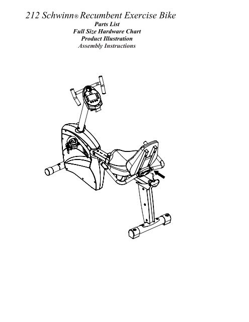
• Replace Warning Label if damaged, illegible, or removed.• We re<strong>com</strong>mend that a minimum distance of 1 meter (39 inches)surrounding the bike is kept clear of all obstructions, including children,bystanders, and pets. This is to ensure adequate clearance for easyaccess to the bike and to avoid any possible contact with the movingpedals<strong>212</strong> <strong>Schwinn</strong> <strong>Recumbent</strong> <strong>Bike</strong> Parts List,Hardware Chart, and Assembly InstructionsAssembly of the <strong>212</strong> <strong>Recumbent</strong> <strong>Bike</strong> is divided into 5 easy stages; each<strong>com</strong>prised of only a few setup steps. Before proceeding with the assembly,please read over the easy to follow instructions to familiarize yourself with theprocess.• A flat area of 5’ x 7’ is suggested to assemble and properly use the <strong>212</strong>exercise bike.• You will need the following tools to <strong>com</strong>plete the assembly:5mm Allen wrench (supplied)Open wrench 13mm, 14mm, 15mm (supplied)Phillips screwdriver (supplied)Also, to ensure quick and easy set up of the <strong>212</strong> <strong>Recumbent</strong> <strong>Bike</strong>, please verifythe size and quantity of each of the enclosed assembly hardware. Included is ahandy full size hardware chart and parts list of each of the required assemblyhardware. Simply match up the corresponding hardware to each full sizedrawing.
Parts ListCheck Quantity Description Reference #__ 1 Computer 1__ 1 Handlebars 2__ 4 Computer Screws 3__ 1 Handlebar Post 4__ 15 Allen Bolt 8x1.25x16L 5__ 4 Wavy Washer 6__ 1 Upper HR Wire 7__ 1 Upper Computer Wire 8__ 1 Lower Computer Wire 9__ 1 Lower HR Wire 10__ 1 Front Stabilizer 11__ 4 Flathead Screw 8x16L 12__ 1 Main Frame 13__ 1pr Pedals 14__ 19 Flat Washer 15__ 1 Seat Rail Post 16__ 1 Rear Stabilizer 17__ 1 Seat Rail 18__ 1 Seat Rail HR Wire 19__ 1 Seat Handlebar 20__ 1 Seat Adjustment Knob 21__ 1 Small Flat Washer 22__ 1 Seat Bottom 23__ 8 Allen Bolt 8x1.25x45L 25__ 1 Seat Support Frame 26__ 1 Seat Back 27__ 1pr Bottle Holder 28__ 8 Screw 5x14L 29__ 1 AC Adaptor 72
Stage#1Hardware ChartStage#2Stage#5Screws M8xP1.25x16mmFlat Washer? 8*? 16*2TScrews M5x14LAllen Bolt M8xP1.25x16mmStage#3Stage#4Flat Washer? 8*? 16*2T Screws M8xP1.25x mmFlat Washer? 8*? 16*2TScrews M8xP1.25xmmStage#6Stage#10Screws M8xP1.25x16mmFlat Washer? 8*? 16*2TScrews M8xP1.25x16mmFlat Washer? 8*? 16*2TStage#8Allen Bolt M8xP1.25x16mmScrewdriverAllen KeyNote: Please verify you have all correct parts and quantities before assemblingunit.If you are missing items, are short quantities, or have damaged <strong>com</strong>ponents,please contact <strong>Schwinn</strong> at 1.800.864.1270.
<strong>212</strong> Assembly Drawing with ReferenceNumbers
Replacement Parts ListReference # Description Part #__ 1 Computer 18143__ 2 Handlebars 18200__ 3 Computer Screws 18094__ 4 Handlebar Post 18196__ 5 Allen Bolt 8x1.25x16L 18001__ 6 Wavy Washer 18098__ 7 Upper HR Wire 18086__ 8 Upper Computer Wire 18085__ 10 Lower HR Wire N/A__ 11 Front Stabilizer N/A__ 12 Flat head Screw 8x16L 18136__ 14 Pedals 18255__ 15 Flat Washer 18101__ 16 Seat Rail Post 18203__ 17 Rear Stabilizer 18126__ 18 Seat Rail 18080__ 19 Seat Rail HR Wire 18082__ 20 Seat Handlebar 18207__ 21 Seat Adjustment Knob N/A__ 22 Small Flat Washer 18225__ 23 Seat Bottom 18246__ 25 Allen Bolt 8x1.25x45L 18072__ 26 Seat Support Frame 18201__ 27 Seat Back 18247__ 28 Bottle Holder 18135__ 29 Screw 5x14L N/A__ 72 AC Adaptor 18007Deleted: 18064Deleted: 18189Deleted: 18198Deleted: 18191Deleted: 18214Deleted: 18250Deleted: 18250
InstructionsIMPORTANT!: To ensure ease of assembly please verify the size andquantity of all the required assembly hardware and parts with the enclosedparts list and full size hardware chart.Each step of the assembly process has been broken down into 6 easy-to-followstages. Please take just a few moments to read over these instructions tofamiliarize yourself with the process to make assembly quick and trouble-free.Assemble Seat and Handle BarAssembly Stage #1Assembly hardware required: (8) M8 Allen Bolts 45 mm long (item #25)(4) M8 Allen Bolts 16 mm long (item #5)(12) Flat Washer Ø8* Ø 16*2T(item #15)(8) Screws M4x14L (item #29)Step 1: Attach HANDLEBAR ASSEMBLY (#20) to SEAT FRAME (#26) with the 4ALLEN BOLTS 16mm (#5) and 4 FLAT WASHERS (#15). Tighten bolts with theprovided Allen wrench.Step 2: Attach the right and left WATER BOTTLE HOLDERS (#28) with theSCREWS (#29) to the underside of the SEAT BOTTOM (#23) using the providedscrewdriver.
Step 3: Attach SEAT (#23) to SEAT FRAME (#26) with 4 ALLEN BOLTS 45mm(#25) and 4 WASHERS (#15). Tighten Bolts.Step 4: Attach SEAT BACK (#27) to SEAT FRAME (#26) with 4 ALLEN BOLTS45mm (#25) and 4 WASHERS (#15). Tighten Bolts.Note: Finished seat should look like picture below:
Assembly Stage #2Attach Rear Stabilizer and Seat Rail toSeat AssemblyAssembly hardware required: (4) M8 Allen Bolts 16mm (item #5)(4) Flat Washers Ø8 * Ø16 * 2T (item#15)(2) Flat Head Screws (item #12)Step 5: Attach the REAR STABILIZER (#17) to the SEAT RAIL POST (#16) with 2FLAT HEAD SCREWS (#12). Tighten bolts.Step 6: Attach SEAT RAIL (#18) to SEAT RAIL POST (#16) with 4 FLATWASHERS (#15) and 4 ALLEN BOLTS (#5). Tighten boltsStep 7: Insert SEAT PIN ADJUSTMENT KNOB (#3) into SEAT FRAME (#8).Slide the seat assembly from stage 1 onto the SEAT RAIL (#9). Tighten seatassembly to the rail with the SEAT PIN ADJUSTMENT KNOB (#3). Insert HRCABLE (#47) into HR input on the back of the seat assembly (inset picture).
Assembly Stage #3Attach Front Stabilizer Tube and Pedals to Main UnitAssembly Hardware Required: (2) Flat Head Screws (item #12)Step 8: Attach FRONT STABILIZER TUBE (#11) to the MAIN UNIT (#13) with 2FLAT HEAD SCREWS (#12). Tighten Bolts with provided wrench.Step 9: Attach RIGHT PEDAL (#14) to the right crank arm on the MAIN UNIT(#31). Thread the pedal onto the crank arm and then tighten with pedal wrench.Attach LEFT PEDAL (#14) to the left crank arm on the MAIN UNIT (#13). Threadthe pedal onto the crank arm and then tighten with pedal wrench. Note: There is aright pedal and a left pedal, marked by R and L. The threading on the left pedalis reversed from the right pedal. Counterclockwise rotation tightens whileClockwise rotation loosens on the left pedal. To avoid stripping of the threads becareful to use the proper pedal.Attach PEDAL STRAPS (#18) to each PEDAL (#14). Again, each strap is labeledwith an R or an L corresponding to the right and left pedal straps.
Assembly Stage #4Attach Seat Rail to Main UnitAssembly Hardware Required: (3) Allen Bolts 16 mm long (item #5)(3) Flat Washers (item #15)Step 10: Attach the SEAT RAIL HR WIRE (#19) to the LOWER HR WIRE (#10).Carefully slide the seat rail assembly onto the receiver on the MAIN UNIT (#13).CAUTION! Be careful not to pinch the heart rate wires between the seat rail andthe receiver on the main unit. Failure to do so could cause damage to the wires andcause the heart rate feature not to function. Attach the SEAT RAIL to the MAINUNIT (#13) with 3 16mm ALLEN BOLTS (#5) and 3 FLAT WASHERS (#15). Tightenbolts. Attach the heart rate wire to the rear port on the back of the seat.
Assembly Stage #5Attach Handlebar Assembly and Run Cabling Through Handlebar PostAssembly Hardware Required:NONEStep 11: Slide the HANDLEBAR ASSEMBLY (#2) into the receiver on theHANDLEBAR POST (#4). Slide the threaded post into the slider tube and attach theHANDLEBAR ASSEMBLY SLIDER TUBE (#2) and the HANDLEBAR POST (#4) bythreading the ADJUSTMENT KNOB (#21) and the SMALL FLAT WASHER (#22) intothe threaded post. Place the end cap on the end of the slider tube on the HANDLEBARASSEMBLY (#2).Step 12: Take the UPPER HR WIRE (#7) and the UPPER COMPUTERWIRE (#8) and slide them through the HANDLEBAR POST (#4) aspictured above.
Assembly Stage #6Attach Console Mast to Main UnitAssembly Hardware Required: (4) Allen Bolts 16 mm long (item #5)(4) Curved Washers (item #6)
(4) Computer Screws (item #3)Step 13: Before sliding the HANDLEBAR POST (#4) onto the MAIN UNIT (#13),attach both HR CABLES (#7 & #10) as well as the COMPUTER CABLE (#8 & #9).Slide the HANDLEBAR POST (#4) onto the MAIN UNIT (#13). Fasten with 4 BOLTS(#22) and 4 CURVED WASHERS (#19). Tighten with provided Allen wrench.Step 14: Attach UPPER COMPUTER CABLE (#7) and HR CABLE (#8) to under sideof COMPUTER (#1). Place COMPUTER (#1) on top of HANDLEBAR ASSEMBLY(#2), the reading rack should wrap around the bottom of the COMPUTER (#1). AttachCOMPUTER (#1) to HANDLEBAR ASSEMBLY (#2) with COMPUTER MOUNTINGSCREWS (#3). (In <strong>com</strong>puter back) Tighten with Phillips head screwdriver.Step 15: Plug AC ADAPTOR (#71) into the wall and into the recumbent bike. ThePOWER PLUG (#72) on the bike is located at the front end of the MAIN UNIT (#13)just above the FRONT STABILIZER TUBE (#11)Seat AdjustmentFor best results, the seat should be adjusted for your height.1. Unlock “seat locking” mechanism.2. Adjust seat location so that with feet on the pedals, you can <strong>com</strong>fortably reachpedal at full extension.That’s it!You’re finished and now you can begin to reach your fitness goals!Please reference the Owner’s Manual for information regarding <strong>com</strong>puteroperation, product maintenance, warranty information, and general fitness andexercise guidelines.<strong>Schwinn</strong> Customer Service1.800.864.1270
Troubleshooting the <strong>Schwinn</strong> <strong>212</strong> <strong>Recumbent</strong><strong>Exercise</strong> <strong>Bike</strong>TIP: Use assembly diagram(s) as reference when troubleshooting unit.PROBLEM: Computer will not start, function, or is blank…(SOLUTION):1. Ensure the batteries the unit is plugged into a 110v outlet.2. Check the wiring connections and connector orientationmade to the <strong>com</strong>puter.3. Confirm that wiring (cable assembly) has not beendamaged4. If <strong>com</strong>puter still fails to start please call 1.800.864.1270for assistance.PROBLEM: No Heart Rate on <strong>com</strong>puter…(SOLUTION):1. Check the connections made at the <strong>com</strong>puter andhandlebars2. If heart rate still fails to work call 1.800.864.1270 forassistance.PROBLEM: <strong>Bike</strong> will not sit level…(SOLUTION):1. Adjust the levelers on the rear stabilizer.Note: If you need additional support information or assistance in troubleshooting,please contact us at: 1.800.864.1270