

Catalog ST PCS 7, June 2012 - Siemens
Catalog ST PCS 7, June 2012 - Siemens
Catalog ST PCS 7, June 2012 - Siemens
- No tags were found...

You also want an ePaper? Increase the reach of your titles
YUMPU automatically turns print PDFs into web optimized ePapers that Google loves.
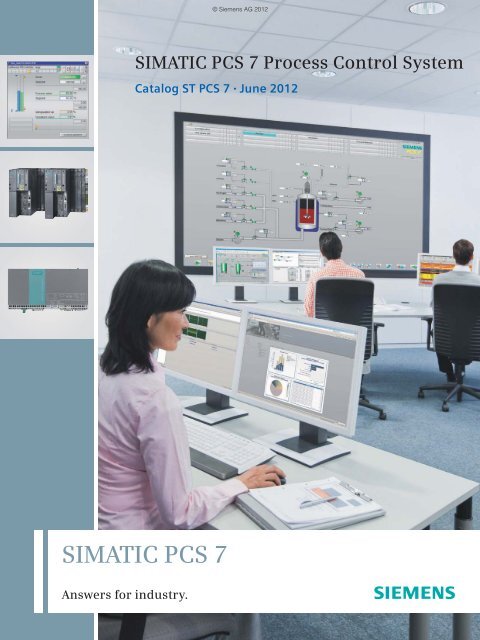
© <strong>Siemens</strong> AG <strong>2012</strong>SIMATIC <strong>PCS</strong> 7 Process Control System<strong>Catalog</strong> <strong>ST</strong> <strong>PCS</strong> 7 • <strong>June</strong> <strong>2012</strong>SIMATIC <strong>PCS</strong> 7Answers for industry.
© <strong>Siemens</strong> AG <strong>2012</strong>Related catalogsSIMATIC <strong>ST</strong> <strong>PCS</strong> 7.1Add-ons for theSIMATIC <strong>PCS</strong> 7Process Control SystemPDF (E86060-K4678-A121-A9-7600)Process Automation FI 01Field Instruments forProcess AutomationE86060-K6201-A101-B4-7600SIMATIC <strong>ST</strong> <strong>PCS</strong> 7.2Migration solutions withthe SIMATIC <strong>PCS</strong> 7Process Control SystemPDF (E86060-K4678-A131-A5-7600)SITRAINTraining for Automation andIndustrial SolutionsOnly available in GermanE86060-K6850-A101-C2ITCSIMATIC <strong>ST</strong> 70Products forTotally Integrated Automationand Micro AutomationE86060-K4670-A101-B3-7600SIMATIC HMI /<strong>ST</strong> 80/<strong>ST</strong> PCPC-based AutomationHuman Machine Interface SystemsPC-based AutomationE86060-K4680-A101-B8-7600Products for Automation CA 01and DrivesInteractive <strong>Catalog</strong>DVD: E86060-D4001-A510-D1-7600Industry MallInformation and Ordering Platformin the Internet:www.siemens.com/industrymallIndustrial CommunicationSIMATIC NETIK PIE86060-K6710-A101-B7-7600
© <strong>Siemens</strong> AG <strong>2012</strong>SIMATIC <strong>PCS</strong> 7SIMATIC <strong>PCS</strong> 7Process Control System V8.0<strong>Catalog</strong> <strong>ST</strong> <strong>PCS</strong> 7 · <strong>June</strong> <strong>2012</strong>Industrial Workstation/IPC1Engineering system2Operator system3Supersedes:<strong>Catalog</strong> <strong>ST</strong> <strong>PCS</strong> 7· December 2011Refer to the Industry Mall for current updatesof this catalog:www.siemens.com/industrymallThe products contained in thiscatalog can also be found in theInteractive <strong>Catalog</strong> CA 01.Order No.:E86060-D4001-A510-D1-7600Please contact your local <strong>Siemens</strong> branch© <strong>Siemens</strong> AG <strong>2012</strong>The products and systemsdescribed in thiscatalog are manufactured/distributedunderapplication of a certifiedquality managementsystem in accordancewith DIN EN ISO 9001(Certified RegistrationNo. 1323-QM). The certificateis recognized byall IQNet countries.System componentsTechnology componentsProcess data archiving and4reportingMaintenance Station5Automation systems6Communications7Process I/O8SIMATIC <strong>PCS</strong> 7 Software and9System documentationBatch automation10Route control11Safety Integrated for12Process AutomationTeleControl13PowerControl14IT Security15Interfacing IT systems16Compact systems17Previous versions18Printed on paper fromsustainably managedforests and controlledsources.www.pefc.orgOtherUpdate/upgrade packages19Appendix20
2 <strong>Siemens</strong> <strong>ST</strong> <strong>PCS</strong> 7 · <strong>June</strong> <strong>2012</strong>© <strong>Siemens</strong> AG <strong>2012</strong>
© <strong>Siemens</strong> AG <strong>2012</strong>Answers for industry.<strong>Siemens</strong> Industry answers the challenges in themanufacturing and the process industry as well as inthe building automation business. Our drive and automationsolutions based on Totally Integrated Automation (TIA) andTotally Integrated Power (TIP) are employed in all kindsof industry. In the manufacturing and the process industry.In industrial as well as in functional buildings.<strong>Siemens</strong> offers automation, drive, andlow-voltage switching technology aswell as industrial software from standardproducts up to entire industry solutions.The industry software enables ourindustry customers to optimize the entirevalue chain – from product designand development through manufactureand sales up to after-sales service. Ourelectrical and mechanical componentsoffer integrated technologies for the entiredrive train – from couplings to gearunits, from motors to control and drivesolutions for all engineering industries.Our technology platform TIP offers robustsolutions for power distribution.The high quality of our productssets industry-wide benchmarks.High environmental aims are part ofour eco-management, and we implementthese aims consistently. Rightfrom product design, possible effects onthe environment are examined. Hencemany of our products and systems areRoHS compliant (Restriction of HazardousSubstances). As a matter of course,our production sites are certified accordingto DIN EN ISO 14001, but to us,environmental protection also meansmost efficient utilization of valuableresources. The best example are ourenergy-efficient drives with energy savingsup to 60 %.Check out the opportunities ourautomation and drive solutions provide.And discover how you can sustainablyenhance your competitive edge with us.<strong>Siemens</strong> <strong>ST</strong> <strong>PCS</strong> 7 · <strong>June</strong> <strong>2012</strong>3
© <strong>Siemens</strong> AG <strong>2012</strong>Setting standards inproductivity and competitiveness.Totally Integrated Automation.4 <strong>Siemens</strong> <strong>ST</strong> <strong>PCS</strong> 7 · <strong>June</strong> <strong>2012</strong>
© <strong>Siemens</strong> AG <strong>2012</strong>TIA is characterized by its unique continuity.It provides maximum transparency at all levelswith reduced interfacing requirements – coveringthe field level, production control level, up to thecorporate management level. With TIA you alsoprofit throughout the complete life cycle of yourplant – starting with the initial planning stepsthrough operation up to modernization, wherewe offer a high measure of investment security resultingfrom continuity in the further developmentof our products and from reducing the number ofinterfaces to a minimum.The unique continuity is already a definedcharacteristic at the development stage ofour products and systems.The result: maximum interoperability – coveringthe controller, HMI, drives, up to the processcontrol system. This reduces the complexity ofthe automation solution in your plant. You willexperience this, for example, in the engineeringphase of the automation solution in the form ofreduced time requirements and cost, or duringoperation using the continuous diagnostics facilitiesof Totally Integrated Automation for increasingthe availability of your plant.Thanks to Totally Integrated Automation, <strong>Siemens</strong> providesan integrated basis for the implementation of customizedautomation solutions – in all industries from inbound tooutbound.<strong>Siemens</strong> <strong>ST</strong> <strong>PCS</strong> 7 · <strong>June</strong> <strong>2012</strong>5
© <strong>Siemens</strong> AG <strong>2012</strong>Integrated power distributionfrom one source.Totally Integrated Power.6 <strong>Siemens</strong> <strong>ST</strong> <strong>PCS</strong> 7 · <strong>June</strong> <strong>2012</strong>
© <strong>Siemens</strong> AG <strong>2012</strong>CommunicationIndustrial EthernetProcess/industrial automationIEC 61850PROFIBUSPROFINETBACnetKNXnet/IPKNXProducts and systemsLowvoltageTransformerMediumvoltageInstallationtechnologyBuildingautomationPlanning and dimensioningSIMARIS project SIMARIS design SIMARIS curvesElectrical power distribution requiresintegrated solutions. Our answer:Totally Integrated Power (TIP). Thisincludes tools and support for planningand configuration and a complete, optimallyharmonized product and systemportfolio for integrated power distributionfrom medium-voltage switchgearright to socket outlets.The power distribution products andsystems can be interfaced to buildingor industrial automation systems(as part of Total Building Solutions orTotally Integrated Automation) via communicationcapable circuit breakers andmodules, allowing the full potential foroptimization that an integrated solutionoffers to be exploited throughout theproduct cycle – from planning rightthrough to installation and operation.Thanks to a comprehensive energymanagement system, power flowscan be made transparent and theenergy consumption of individualloads can be calculated and allocated.Building operators can thus identifypower-intensive loads and implementeffective optimization measures.With its products and systems, TotallyIntegrated Power forms the basis forthis functionality and guaranteesgreater cost-efficiency in industrialapplications, infrastructure andbuildings.<strong>Siemens</strong> <strong>ST</strong> <strong>PCS</strong> 7 · <strong>June</strong> <strong>2012</strong>7
© <strong>Siemens</strong> AG <strong>2012</strong>SIMATIC <strong>PCS</strong> 7performance you trustMobile Client<strong>PCS</strong> 7BOXOperator System (OS)Single StationIndustrialWireless LANOS/Batch/Route Control/Maintenance clientsIndustrial Ethernet, terminal bus, single/redundantOSserverBatchserverIndustrial Ethernet, plant bus, single/redundantAutomationsystem withPROFINET <strong>PCS</strong> 7 <strong>PCS</strong> 7AS RTX AS mEC RTXwith S7-300 I/OsET 200proET 200M ET 200MStandardautomation systemsZone 2 Zone 1PROFINETEx operatorterminalWireless HARTET 200M, Ex I/O, HARTWeighing systemsET 200MPROFIBUS DP-iSAS-InterfaceModbus, serial connectionET 200SET 200iSP HARTIntegratedpowermanagementPROFIBUS DPPA linkPROFIBUS PAAFDAFDiSPA link/FF linkPROFIBUS PA/FOUNDATIONFieldbus H1(PA/FF H1)Integrated drives8 <strong>Siemens</strong> <strong>ST</strong> <strong>PCS</strong> 7 · <strong>June</strong> <strong>2012</strong>
© <strong>Siemens</strong> AG <strong>2012</strong>Web Client- OS- MaintenanceData MonitorERPWeb Server/Open<strong>PCS</strong> 7ArchiveserverEthernet, Office LANNetworkprinterMES/MISSIMATIC ITPlant LifecycleManagementCOMOSFrontFirewallEngineeringStationsBackFirewallRoute ControlserverMaintenanceserverTeleControlOS serverFault-tolerantautomation systemsET 200M Zone 2 Zone 1single/redundantY-linkMTAPROFIBUS DP-iSET 200iSPSafety-relatedautomation systemsET 200iSPET 200MStandard andF modulesET 200MF modulesZone 1WANConverter(Protocols:SINAUT <strong>ST</strong>7, DNP3,IEC 60870-5,Modbus)Communication(Wireless, phone,internet)RTUs(Type depends onprotocol)Third-partyRTUGas analysisPA link/FF linkAFDAFSPA/FF H1AFDiSPA linkAFDPROFIBUS PAAFDET 200SS7-300ET 200proS7-400 (H)PA link/FF linkAFDPA/FF H1AFDiSET 200<strong>ST</strong>eleControl<strong>Siemens</strong> <strong>ST</strong> <strong>PCS</strong> 7 · <strong>June</strong> <strong>2012</strong>9
© <strong>Siemens</strong> AG <strong>2012</strong>Totally Integrated Automationwith SIMATIC <strong>PCS</strong> 7SIMATIC <strong>PCS</strong> 7 is one of the internationalleaders in process controlsystems, and has the potential toimplement innovative solutions for thespecial challenges associated with theprocess industry. The functionaldiversity, flexibility, and performance ofthe current version 8.0 mean thatSIMATIC <strong>PCS</strong> 7 pushes the limits of atypical process control system, and itstechnological enhancements offermany additional possibilities and newperspectives.SIMATIC <strong>PCS</strong> 7 benefits from itsseamless integration in <strong>Siemens</strong>Totally Integrated Automation (TIA),a complete range of matched products,systems, and solutions for all hierarchylevels of industrial automation –from the enterprise management level,to the control level, all the way downto the field level. This enables uniform,customer-specific automation in allsectors of manufacturing, process,and hybrid industry.An important advantage of the consistencyof the product and systemspectrum and the solutions based uponthis spectrum is that faster and moreprecise control sequences, as well asintegrated security functions of sharedhardware, engineering, andengineering tools can be used forautomation of continuous and discontinuousprocesses. Perfect interplay ofall components makes it possible foryou to sustainably produce in higherquality and to establish new productssignificantly faster on the market.10 <strong>Siemens</strong> <strong>ST</strong> <strong>PCS</strong> 7 · <strong>June</strong> <strong>2012</strong>
© <strong>Siemens</strong> AG <strong>2012</strong>Performance you trustIn process engineering plants, theprocess control system is the startingpoint for optimal value added:All procedures and processes can beoperated, monitored and influencedwith the process control system.The more powerful the process controlsystem, the more effectively this potentialcan be used. For this reason, performanceis in the foreground withSIMATIC <strong>PCS</strong> 7, alongside scalability,flexibility, and integration. Starting withplanning and engineering, the processcontrol system offers powerful tools,functions and features for cost-effectiveand efficient plant operation through allphases of the plant life cycle.Performance through integrationIntegration is one of the specialstrengths of SIMATIC <strong>PCS</strong> 7.This has many aspects:• Horizontal integration into TIA• Vertical integration into hierarchicalcommunication• System-integrated tools forengineering tasks• Integration of the field level,including drives, switchgear, etc.• Integrated functions, e.g. for batchprocess automation, route control,process safety, energy management,telecontrol tasks, etc.Horizontal integrationA system for integrated automation ofthe entire process chain, from incomingraw materials to outgoing goods –this is one of the decisive advantagesresulting from the seamless integrationof SIMATIC <strong>PCS</strong> 7 into Totally IntegratedAutomation.The process control system is mainlyresponsible for automating the primaryprocesses here, but it can do muchmore: All auxiliary facilities, as well asthe electrical infrastructure in the formof low-voltage or medium-voltageswitchgear and the building managementsystem, can also be integratedinto the system.Integration of selected SIMATICstandard components – automationsystems, industrial PCs, networkcomponents, or distributed process I/O– into the process control system guaranteesoptimum interaction of individualcomponents, and secureseconomic benefits such as simple selection,reduced stock keeping, and globalsupport.<strong>Siemens</strong> <strong>ST</strong> <strong>PCS</strong> 7 · <strong>June</strong> <strong>2012</strong>11
© <strong>Siemens</strong> AG <strong>2012</strong>Life cycle &Remote servicesIntegratedengineeringPlant assetmanagementAPCOptimizationInformationmanagementSIMATIC <strong>PCS</strong> 7EnergymanagementIntegratedpackage unitsBatch processesIntegratedswitchgearMaterial transportIntegratedMCC & drivesIntegratedfield devicesSafetyIntegratedIntegratedtelecontrolVertical integrationThe hierarchal communication of acompany encompasses the field level,the control level, and the process level,up to management and enterpriseresource planning (ERP). Thanks to standardizedinterfaces – based on internationalindustry standards as well asinternal interfaces – SIMATIC <strong>PCS</strong> 7 isable to provide process data for analysis,planning, coordination, and optimizationof plant sequences or productionand business processes – in real time,and at any location in the company.Central engineeringSIMATIC <strong>PCS</strong> 7 convinces with gradedfunctional diversity, consistent operatorcontrol philosophy, and uniformly structuredengineering and managementtools. A central engineering system witha coordinated range of tools for integratedsystem engineering and configuringof batch automation, safety functions,material transport or telecontrolsystems creates value added over theentire life cycle. Reductions in configuringand training costs result in minimizationof total cost of ownership(TCO) over the entire plant life cycle.Functional diversityDepending on the typical process automationor customer-specific requirements,SIMATIC <strong>PCS</strong> 7 can be functionallyexpanded for the following, forexample:•Batch process automation(SIMATIC BATCH)• Functional safety and protectionfunctions (Safety Integrated forProcess Automation)• Route control for material transport(SIMATIC Route Control)• Telecontrol of remote units(SIMATIC <strong>PCS</strong> 7 TeleControl)• Automation of electrical switchgear(SIMATIC <strong>PCS</strong> 7 PowerControl)Further additional functions that arealso integrated, or can be integrated,seamlessly into the control system makeoptimization of processes and reductionsin operating costs possible.SIMATIC <strong>PCS</strong> 7 has, for example, toolsfor energy and asset management, andit offers higher quality closed-loopcontrol functions, as well as industryspecificautomation solutions andlibraries.12 <strong>Siemens</strong> <strong>ST</strong> <strong>PCS</strong> 7 · <strong>June</strong> <strong>2012</strong>
© <strong>Siemens</strong> AG <strong>2012</strong>Customized performanceThanks to a unique scalable systemarchitecture, SIMATIC <strong>PCS</strong> 7 creates theideal basis for cost-effective implementationof individual automation solutionsand economic operation ofprocess plants.SIMATIC <strong>PCS</strong> 7 users derive sustainedprofit from a modular system platformbased on standard SIMATIC components.Its uniformity enables flexiblescaling of hardware and software, aswell as perfect interaction both withinthe system and beyond system limits.The architecture of the SIMATIC <strong>PCS</strong> 7Process Control System is designed insuch a manner that instrumentationand control can be configured in accordancewith customer requirements andoptimally matched to the dimensions ofthe plant. The control system can besubsequently expanded or reconfiguredat any time if there is an increase incapacity or a technological modification.When the plant grows, SIMATIC<strong>PCS</strong> 7 simply grows along with it –without the provision of expensivereserve capacities.Performance in engineeringWith regard to planning and engineering,performance can be equatedwith minimizing time and costs.In conjunction with COMOS, SIMATIC<strong>PCS</strong> 7 offers a unique approach here:Integrated planning workflow from thedescription of the process to the automationprogram.A standardized system interface, strictlyobject-oriented working, and centralizeddata management mean dataconsistency across all planning steps,including automatically updated systemdocumentation.Engineering using other planning toolsis also mastered extremely efficiently bySIMATIC <strong>PCS</strong> 7 by means of theAdvanced Engineering System (AdvES).This can be used to import plant datafrom CAD/CAE tools without problems.It additionally allows automatic generationof the AS configuration thanks tosimple multiplication of process tagtypes and model solutions, as well asparameter processing.<strong>Siemens</strong> <strong>ST</strong> <strong>PCS</strong> 7 · <strong>June</strong> <strong>2012</strong>13
© <strong>Siemens</strong> AG <strong>2012</strong>Performance in operationProcess control also becomes morecomplex due to the multi-layer nature ofautomation engineering and theincreased merging with informationtechnology. Intuitive and fault freeoperation is therefore more importantthan ever with regard to efficientworking and the minimization of downtimesand servicing requirements.Using effective Advanced ProcessControl (APC) functions and an excellentoperator system, SIMATIC <strong>PCS</strong> 7supports optimization as well as userfriendlyand safe control of the process.Monitoring of product quality andperformance indicators additionallyallows the process to be operated moreeconomically. At the same time,SIMATIC <strong>PCS</strong> 7 convinces with highflexibility, plant availability, and investmentsecurity.Process control and maintenanceSIMATIC <strong>PCS</strong> 7's operator system isused to monitor process operationusing various views, and permits interventionswhen necessary. Its architectureis flexible and scalable – fromsingle-user systems up to multi-usersystems with a redundant client/serverarchitecture. The operator interfacetakes account of the current specificationsof NAMUR (user association ofautomation technology in the processindustries) and PI (Profibus International)and offers a high level of userfriendlinessfor simple, intuitive interactionwith the plant. Ergonomic symbols,task-oriented faceplates, uniform representationof status information, andoptimized alarm functions allow safeprocess control.The alarm management function integratedin SIMATIC <strong>PCS</strong> 7 is able to focuson essential alarms and to specificallyguide the operator in exceptionalcircumstances. In this way, it systematicallyreduces the workload of operatingstaff.Preventive and predictive maintenancestrategies reduce total cost ofownership. With the SIMATIC <strong>PCS</strong> 7Maintenance Station, maintenancepersonnel always have a watchful eyeon critical production equipment suchas pumps, valves, distillation columns ormotors, and can carry out the relevantmaintenance measures in good timebefore servicing is required –independent of the maintenance planand without the risk of an unplannedplant standstill.Process optimizationSIMATIC <strong>PCS</strong> 7 supports process optimizationin many different manners,including:• Control Performance Monitoring• Advanced Process Control•Process HistorianThe Control Performance Monitoringfunction monitors and signals thecontrol quality of the closed-loopcontrol block. If the performancedeclines, the controller can be optimizedin good time or specific maintenancemeasures can be initiated.The integrated I&C libraries ofSIMATIC <strong>PCS</strong> 7 also provide higherquality closed-loop control functionswith which cost-effective AdvancedProcess Control applications can beimplemented: multi-variable control,predictive control, or override control. Itis thus possible to effectively improveprofitability, product quality, safety, andenvironmental protection in small andmedium-sized plants.Current and historic process data formthe basis of all optimization. Secure anduser-friendly real-time data storage andanalysis is handled using the ProcessHistorian. The process values,messages, and batch data managed inthe database of the Process Historiancan be called extremely rapidly. Userspecificprocessing and visualization ofthis historic data are supported by theinformation server, which is a reportingsystem based on the MicrosoftReporting Services.14 <strong>Siemens</strong> <strong>ST</strong> <strong>PCS</strong> 7 · <strong>June</strong> <strong>2012</strong>
© <strong>Siemens</strong> AG <strong>2012</strong>Additional functionality can beintegrated using add-on productsModularity, flexibility, scalability, andthe openness of SIMATIC <strong>PCS</strong> 7 offeroptimal prerequisites for integratingsupplemental components and solutionsin the process control system in anapplicative manner and thus extend andround off its functionality.Many supplementary add-on productsfor SIMATIC <strong>PCS</strong> 7 have been developedby <strong>Siemens</strong> as well as by external partners(see <strong>Catalog</strong> <strong>ST</strong> <strong>PCS</strong> 7.1, Add-onsfor the SIMATIC <strong>PCS</strong> 7 Process ControlSystem). These software packages andhardware components authorized bythe system manufacturer enable costeffectiveimplementation of SIMATIC<strong>PCS</strong> 7 for special automation tasks.Migration to SIMATIC <strong>PCS</strong> 7Many systems and plants must nowbe expanded and modernized to ensurethat companies can continue to provideproducts complying with marketrequirements. However, since theinstalled basis of hardware, applicationsoftware and know-how of the operatingand maintenance engineers representsan enormous value, the safeguardingof investments for companiesoperating the plants is always assigneda high priority during all modernizationplans.Migration spectrum<strong>Siemens</strong> recognized the significanceof migration for process automation atan early stage, and has for many yearsoffered a wide range of innovativemigration products and solutions forits globally proven systems, such asAPACS+ or TELEPERM M.Migration of old systems from othermanufacturers such as ABB, Honeywell,Emerson or Invensys has since becomefirmly established. The universal,OPC-coupled SIMATIC <strong>PCS</strong> 7/Open OSis being increasingly used with whichany systems can be integrated into theuniform operating concept of SIMATIC<strong>PCS</strong> 7. Engineering tools such as DBA(Data Base Automation), or thepowerful migration platform forcontroller engineering, accelerate thechangeover from old systems toSIMATIC <strong>PCS</strong> 7. This is all supplementedby individual solutions including thosefor communication between the oldand new systems, or for fast inclusion inmigration projects, e.g. specificgateways, connectors, cables, and fieldtermination assemblies (FTAs).Experts with experience of migrationIn view of the complexity of manymigration projects, decisive prerequisitesfor migration success include theanalysis and design of the correct procedure,including a realistic assessment ofthe opportunities and risks.The migration experts at <strong>Siemens</strong>have already acquired relevant experiencein migrating the most diversesystems. This know-how is concentratedin Migration Support Centers thatsupport migration projects worldwideby means of analyses, concepts andpowerful tools.If desired, <strong>Siemens</strong> works closely withthe customer's system integrators whenimplementing migration projects, forthey have the know-how gained overmany years, coupled with preciseknowledge of the plant and thecustomer's requirements. For theplant operator, this partnership is theguarantee for an optimal migrationoutcome.For more information on the topic ofmigration, see <strong>Catalog</strong> <strong>ST</strong> <strong>PCS</strong> 7.2,Migration solutions for the SIMATIC<strong>PCS</strong> 7 process control system, and onthe Internet at:www.siemens.com/simatic-pcs7/migration<strong>Siemens</strong> <strong>ST</strong> <strong>PCS</strong> 7 · <strong>June</strong> <strong>2012</strong>15
16 <strong>Siemens</strong> <strong>ST</strong> <strong>PCS</strong> 7 · <strong>June</strong> <strong>2012</strong>© <strong>Siemens</strong> AG <strong>2012</strong>
© <strong>Siemens</strong> AG <strong>2012</strong>Industrial Workstation/IPC11/2 Introduction1/3 SIMATIC Rack PC1/3 Introduction1/12 IPC547D1/20 IPC647C1/27 IPC847C1/33 SIMATIC BOX PC1/33 OS Client 627C1/39 SIMATIC Microbox PC1/39 OS Client 427C1/43 Expansion components1/43 Mouse and keyboard1/44 Multi-monitor graphics cards andprocess monitors1/46 Redundant terminal bus adapter1/47 Smart Card Reader1/48 Signal output<strong>Siemens</strong> <strong>ST</strong> <strong>PCS</strong> 7 · <strong>June</strong> <strong>2012</strong>
Industrial Workstation/IPC© <strong>Siemens</strong> AG <strong>2012</strong>Introduction1 ■ OverviewWe offer a select range of modern and powerful SIMATIC <strong>PCS</strong> 7Industrial Workstations for the systems located above thecontroller level in the SIMATIC <strong>PCS</strong> 7 system architecture, e.g.for:• Engineering• Operating and monitoring (also via Internet/intranet)• Asset management• Batch automation• Route control• Remote control• IT applicationsSIMATIC <strong>PCS</strong> 7 Industrial Workstations based on a SIMATICRack PC of the type IPC547D, IPC647C or IPC 847C areoptimized for use as single station, server or client, and can beexpanded specific to the system.As a supplement to these, the SIMATIC Microbox PC in theversion SIMATIC <strong>PCS</strong> 7 OS Client 427C as well as the SIMATICBox PC in the version SIMATIC <strong>PCS</strong> 7 BOX OS Client 627Cprovide low-cost client alternatives for operator control andmonitoring and for batch automation.■ ApplicationBasic hardware for single station/serverSIMATIC <strong>PCS</strong> 7 Industrial Workstations of the types IPC547D,IPC647C or IPC 847C, which are available for use as singlestation or server, vary in their performance, features, expansionreserves, and length of the product lifecycle. A table comparesthe essential features of these types in the catalog section"SIMATIC Rack PC, introduction", page 1/4 allowing you toquickly narrow down the search for your specific application.You can then use the detailed technical data in the same catalogsection to define this preselection in detail (page 1/6).Basic hardware for clientsCompared to the more compact client versions SIMATIC <strong>PCS</strong> 7OS Client 427C and SIMATIC <strong>PCS</strong> 7 BOX OS Client 627C, clientsbased on a SIMATIC Rack PC have a larger number and greatervariety of interfaces. They therefore offer more expansionoptions and can be used more universally. In multi-monitormode, you can control up to four process monitors with equivalentquality.The SIMATIC <strong>PCS</strong> 7 OS Client 427C particularly convinces withits highly compact and rugged design which allows maintenance-free24/7 operation without fans. The version with solidstatedrive (SSD) is particularly resistant to vibration and shocksince there are no rotating storage media. As a result of thedesign, however, the expansion options of the SIMATIC <strong>PCS</strong> 7OS Client 427C are restricted.The compact and rugged SIMATIC <strong>PCS</strong> 7 BOX OS Client 627Cwith a comparable interface configuration is slightly larger thana client on the basis of the SIMATIC Microbox PC. In return, it isadditionally equipped with a DVD drive and two free slots forexpansion modules. Furthermore, it can also be ordered as adesign version with Panel Front (19", TFT Touch Panel).■ OptionsNotes on the use of other basic hardware and non-SIMATICsoftware<strong>Siemens</strong> guarantees the compatibility of hardware and softwarefor system configurations based on components in this catalog.The system test confirms that the system software of theSIMATIC <strong>PCS</strong> 7 process control system can be run on the basichardware offered in this catalog. Despite comprehensive tests, itcannot be excluded that the function of a SIMATIC <strong>PCS</strong> 7 systemcould be disturbed or interfered with as a result of additionalnon-SIMATIC software, i.e. software which has not beenexplicitly approved for SIMATIC <strong>PCS</strong> 7.If you use hardware other than the basic hardware offered in thiscatalog, or additional non-SIMATIC software, this is at your ownrisk. If compatibility problems arise as a result of these hardware/software components, the support provided for their eliminationis not free of charge.The licenses for plant bus communication via Industrial Ethernet,i.e. for Basic Communication Ethernet (BCE) and CP 1613/1623communication (IE) are bound to the SIMATIC <strong>PCS</strong> 7 IndustrialWorkstations. Depending on the selected type of communication,the SIMATIC <strong>PCS</strong> 7 Industrial Workstations for singlestations and servers are delivered as standard with a networkcard plus BCE license or a CP 1623 plus SIMATIC NETHARDNET IE S7 communications software.If you are using SIMATIC <strong>PCS</strong> 7 V8.0 on other computers (notSIMATIC <strong>PCS</strong> 7 Industrial Workstations), you additionally requirea SIMATIC <strong>PCS</strong> 7 BCE V8.0 license (Order no. 6ES7 650-1CD08-2YB5) for all single stations or servers which are connected tothe plant bus via a standard network adapter and not via aCP 1623/CP 1613 A2.1/2 <strong>Siemens</strong> <strong>ST</strong> <strong>PCS</strong> 7 · <strong>June</strong> <strong>2012</strong>
© <strong>Siemens</strong> AG <strong>2012</strong>Industrial Workstation/I<strong>PCS</strong>IMATIC Rack PC■ OverviewWith the SIMATIC <strong>PCS</strong> 7 Industrial Workstation of the typeIPC547D, we offer you an excellent platform for the configurationof single stations, servers or clients for SIMATIC <strong>PCS</strong> 7 V8.0. With■ ApplicationSpecially optimized versions are available for operation assingle stations, servers or clients. The operating system and thefollowing ES/OS software of the SIMATIC <strong>PCS</strong> 7 process controlsystem are factory installed:• Single station: <strong>PCS</strong> 7 Engineering Software for AS/OS(including OS Runtime software)• Server: <strong>PCS</strong> 7 OS Software Server• Client: <strong>PCS</strong> 7 OS Software ClientYou only need the corresponding licenses in order to use thepreinstalled SIMATIC <strong>PCS</strong> 7 software.Introductionits all-round capabilities it is ideal for numerous applications inprocess automation. The more powerful types, IPC647C andIPC847C, are excellent alternatives to meet higher requirements.Because the basic components such as chipset, processor orECC memory, are identical, many technical specifications of theIPC647C and IPC847C types are comparable. The essentialdifferences result from the different overall heights. Since theIPC647C is only half as high as IPC847C, the number and varietyof the free slots are reduced in this case. On the other hand, themore compact design requires significantly less space andenables higher packing densities in the control cabinet. Thisallows the realization of space-saving designs.The IPC847C best equipped and is the most powerful SIMATIC<strong>PCS</strong> 7 Industrial Workstation. Its numerous and varied slotsprovide a great deal of potential for expansion. In contrast toIPC647C, the hardware RAID controller enables hard diskoperation in the RAID Level 5 (high data throughput whenreading combined with redundancy). The IPC847C is predestinedfor use as a server or single station. Since it would be overdimensionedas a client, it is not offered in this version.Note:Please note the standard installation if you use the SIMATIC<strong>PCS</strong> 7 Industrial Workstations within the SIMATIC <strong>PCS</strong> 7 processcontrol system for other tasks, e.g. as basic hardware forSIMATIC BATCH, SIMATIC Route Control, <strong>PCS</strong> 7 TeleControl,<strong>PCS</strong> 7 StoragePlus, Central Archive Server, Process Historian,Information Server, or <strong>PCS</strong> 7 Web Server. You can then expandor discard the existing SIMATIC <strong>PCS</strong> 7 pre-installation, or restoreit using one of the supplied restore DVDs (for details, see sectionrestore DVDs under IPC547D, IPC647C, or IPC847C, page 1/14,1/22 and 1/29).1<strong>Siemens</strong> <strong>ST</strong> <strong>PCS</strong> 7 · <strong>June</strong> <strong>2012</strong>1/3
Industrial Workstation/I<strong>PCS</strong>IMATIC Rack PC© <strong>Siemens</strong> AG <strong>2012</strong>1Introduction■ Application (continued)FeaturesSIMATIC <strong>PCS</strong> 7 Industrial WorkstationIPC547C 1) IPC547D IPC647C IPC847CAvailable SIMATIC <strong>PCS</strong> 7 V6.1+SP4 n – – –pre-installationsV7.0+SP3 n – – –V7.1+SP3 n – n nV8.0 – n n nAvailable versions ES/OS Single Station n n n nOS Server n n n nOS Client n n n –Height 4 HU 4 HU 2 HU 4 HUECC work memory – – n nSoftware RAID controllerRAID1 n n n n(onboard)Hardware RAID controller with RAID1 – – n nbattery backup unitRAID5 – – – nHard disks/SATA n n n nSolid State Drive (SSD)SAS – – n nSSD – n – nNo. of slots PCIe x16 1 1 + 1 physical 1 1(4 lanes connected)PCIe x81 physical1 physical1 physical–(1 lane connected) (1 lane connected) (4 lanes connected)PCIe x4 – – – 3PCIe x1 1 – – –PCI 4 4 1 7Redundant power supply with diagnostics – – n nwithout diagnostics n n – –Lifecycle Marketing 1.5 to 2 years 1.5 to 2 years 3 years 3 yearsReplacement parts/repair3 years 3 years 5 years 5 years1) The SIMATIC <strong>PCS</strong> 7 Industrial Workstation of the type IPC547C is no longeroffered for SIMATIC <strong>PCS</strong> 7 V8.0. It is only available for the predecessorversions V6.1, V7.0 and V7.1 until further notice (see chapter Previousversions)1/4 <strong>Siemens</strong> <strong>ST</strong> <strong>PCS</strong> 7 · <strong>June</strong> <strong>2012</strong>
■ DesignTypes of plant bus communicationA SIMATIC <strong>PCS</strong> 7 workstation in the single station or serverversion can be used in a variety of ways on the IndustrialEthernet plant bus depending on the type and number ofautomation systems connected:© <strong>Siemens</strong> AG <strong>2012</strong>Industrial Workstation/I<strong>PCS</strong>IMATIC Rack PCIntroduction1Interface Software for AS communicationCommunication module CP 1623/CP 1613 A2 SIMATIC NET HARDNET-IE S7 communicationsoftware, licensed for up to four CP 1623/CP 1613 A2 (license for 4 units)with up to 64 AS single stations(not AS Redundancy Stations)The SIMATIC NET HARDNET-IE S7-REDCONNECT PowerPackis suitable for upgrading the SIMATIC NET HARDNET-IE S7communication software (for ordering data, see section"Communication", section "Industrial Ethernet, systemconnection of <strong>PCS</strong> 7 systems", page 7/44).The Industrial Ethernet versions of the SIMATIC <strong>PCS</strong> 7 IndustrialWorkstation for single stations and servers are equipped asstandard with a CP 1623 communication module and SIMATICNET HARDNET-IE S7 communications software. The BCElicense is involved in the BCE versions of the SIMATIC <strong>PCS</strong> 7Industrial Workstation.Upgrade from BCE to CP 1613/1623 communicationOS single stations and OS servers with BCE communication canbe retro-upgraded for communication with CP 1613/1623. Itemsrequired:• Network card for connecting to Industrial Ethernet:- CP 1623 with PCI Express interface or- CP 1613 A2 with conventional PCI interface• S7 communications software for CP 1613/CP 1623- SIMATIC NET HARDNET-IE S7 for communication withAS Single Stations or- SIMATIC NET HARDNET-IE S7-REDCONNECT for communicationwith AS redundancy stations and AS single stationsFor further information and ordering data for the componentsmentioned, see section "Communication", section "IndustrialEthernet, system connection of <strong>PCS</strong> 7 systems", page 7/44.SIMATIC NET HARDNET-IE S7-REDCONNECTcommunication software, licensed for up to fourCP 1623/CP 1613 A2 (license for 4 units)with redundant automation systems(Redundancy Stations)Ethernet card BCE (Basic Communication Ethernet) license with up to 8 AS Single StationsExpansion componentsThe core component of the SIMATIC <strong>PCS</strong> 7 IndustrialWorkstation is a SIMATIC industrial PC without mouse, keyboardand monitor. This basic hardware can be further expandeddepending on the environment of use and customer requirements:• Accessories-Memory modules- Country-specific power supply cable- Tower Kit (IPC547D and IPC847C only)• Expansion components- Mouse and keyboard- Multi-monitor graphics cards and process monitors- Redundant terminal bus adapter- Smart card reader- Signal outputMulti-monitor operation is supported ex factory with two optionalversions:• Multi-monitor graphics card "2 Screens"• Multi-monitor graphics card "4 Screens"However, it can also be installed later. For information on multimonitoroperation as well as the required ordering data for retrofittingmulti-monitor graphics cards, see section "Multi-monitorgraphics cards and process monitors", page 1/44.<strong>Siemens</strong> <strong>ST</strong> <strong>PCS</strong> 7 · <strong>June</strong> <strong>2012</strong>1/5
Industrial Workstation/I<strong>PCS</strong>IMATIC Rack PC© <strong>Siemens</strong> AG <strong>2012</strong>Introduction1 ■ Technical specificationsComparison of the workstation types for SIMATIC <strong>PCS</strong> 7 V8.0Type SIMATIC IPC547D SIMATIC IPC647C SIMATIC IPC847CDesign and equipment featuresDesign19" rack 4HU 2HU 4HUReady for telescopic rails Yes Yes YesHorizontal/vertical Installation Yes/Yes Yes/No Yes/Yes19" fixing bracket with handle; Yes Yes Yesdismountable from outsideTower kit (accessory) Yes No YesDegree of protectionIP30 at front (front cover closed);IP20 at the rear according toEN 60529IP41 at front (front door closed);IP20 at the rear according toEN 60529IP41 at front (front door closed);IP20 at the rear according toEN 60529Dust protectionConforms to IEC 60529 with closedfront doorFilter class G2 EN 779, particles> 0.5 mm are blocked by 99 %With closed front door inconformity with IEC 60529Filter class G2 EN 779, particles> 0.5 mm are blocked by 99 %With closed front door inconformity with IEC 60529Filter class G2 EN 779, particles> 0.5 mm are blocked by 99 %Chipset Intel Q67 Express Mobile Intel QM57 Express Mobile Intel QM57 ExpressCPUProcessor, clock• Intel Core i7-2600 (4C/8T;3.40 GHz, 8 MB Last LevelCache, Turbo Boost 2.0, EM64-T,• Intel Core i7-610E (2C/4T;2.53 GHz, 4 MB Cache,Turbo Boost, VT-x, VT-d, EM64-T)• Intel Core i7-610E (2C/4T;2.53 GHz, 4 MB Cache,Turbo Boost, VT-x, VT-d, EM64-T)VT-x/-d, iAMT)• Intel Core i5-2400 (4C/4T;3.10 GHz, 6 MB Last LevelCache, Turbo Boost 2.0, EM64-T,VT-x/-d, iAMT)• Intel Pentium Dual Core G850(2C/2T; 2.90 GHz, 3 MB LastLevel Cache, EM64-T, VT)Main memory (SDRAM)TypeMaximum configurationStandard configurationMotherboard slotsDual Channel DDR3-1333 SDRAM(PC3-10600), without ECC4 DIMM memory sockets in total;together up to 32 GB2 GB DDR3-1333 SDRAM(2 x 1.0 GB); dual channel4 GB DDR3-1333 SDRAM(2 x 2.0 GB); dual channel8 GB DDR3-1333 SDRAM(2 x 4.0 GB); dual channel12 GB DDR3-1333 SDRAM(2 x 4.0GB + 2x 2.0GB);dual channel16 GB DDR3-1333 SDRAM(4 x 4.0 GB); dual channel4 GB or more can be selected forOS server or ES/OS single station2 GB or more can be selected forOS client4 x PCI1 x PCIe x8 (1 lane)1 x PCIe x161 x PCIe x16 (4 lanes)Modules up to 312 mm in lengthcan be usedDDR3-1066 SDRAM (PC3-8500),with or without ECC2 DIMM memory sockets in total;together up to 8 GB2 GB DDR3 SDRAM (1 x 2.0 GB);single channel2 GB DDR3 SDRAM (2 x 1.0 GB);dual channel, ECC4 GB DDR3 SDRAM (2 x 2.0 GB);dual channel (without/with ECC)6 GB DDR3 SDRAM (1 x 2.0 GB,1 x 4.0 GB); dual channel8 GB DDR3 SDRAM (2 x 4.0 GB);dual channel (without/with ECC)4 GB or more can be selected forOS server or ES/OS single station2 GB or more can be selected forOS client1 x PCI1 x PCIe x8 (4 lanes)1 x PCIe x16Modules up to 312 mm in lengthcan be usedDDR3-1066 SDRAM (PC3-8500),with or without ECC2 DIMM memory sockets in total;together up to 8 GB4 GB DDR3 SDRAM (2 x 2.0 GB);dual channel (without/with ECC)6 GB DDR3 SDRAM (1 x 2.0 GB,1 x 4.0 GB); dual channel8 GB DDR3 SDRAM (2 x 4.0 GB);dual channel (without/with ECC)4 GB or more can be selected forOS server, ES/OS single station orOS client7 x PCI3 x PCIe x41 x PCIe x16Modules up to 312 mm in lengthcan be used1/6 <strong>Siemens</strong> <strong>ST</strong> <strong>PCS</strong> 7 · <strong>June</strong> <strong>2012</strong>
© <strong>Siemens</strong> AG <strong>2012</strong>Industrial Workstation/I<strong>PCS</strong>IMATIC Rack PCIntroduction■ Technical specifications (continued)1Type SIMATIC IPC547D SIMATIC IPC647C SIMATIC IPC847CSlots for drivesOn the frontIndoorsRAID controllerDrivesHard disk (HDD)Solid-State Drive (SSD)DVD burner3 x 5.25" (1 x 5.25" for DVD burnerand 3 x low-profile swap frames for3.5" hard disks)1 x 3.5" (unused)2 x 3.5" for hard disk drives in theinternal drive bay (can beoptionally installed in swap frames)Onboard: Intel PCH RAIDcontroller with Intel Rapid StorageTechnology500 GB or 1 TB SATA 3.5" withNCQ technology50 GB or 100 GB SATA 2.5" withSLC technologyDVD±R/RW 5.25" SATARead:• DVD-ROM: single layer 16x,dual layer 12x• DVD-R/+R: single layer 16x,dual layer 12x• DVD-RW/+RW 13x• CD-ROM/CD-R 48x; CD-RW 40xWrite:• DVD-RAM 12x• DVD+R 24x, DVD+RW 8x,DVD-R 24x, DVD-RW 6x• DVD+R9 (DL) 12x, DVD-RDL 12x• CD-R 48x, CD-RW 32x2 x low-profile swap frames for 3.5"hard disks1 x 12.7 mm slimline for DVDburner2 x 3.5" for hard disk drives in theshock-proof and vibration-proofdrive bay (can be optionallyinstalled in swap frames)Onboard: Mobile Intel QM57Express (5 series SATA RAIDcontroller)Alternative: Hardware (HW) RAIDcontroller in slot PCIe x16500 GB SATA 3.5" with NCQtechnology or 1 TB SAS 3.5" withNCQ technologyNoDVD±R/RW 5.25" SATA SlimlineRead:• DVD-ROM: single layer 8x,dual layer 6x• DVD-R/+R: single layer 8x,dual layer 6x• DVD-RW/+RW 8x, DVD-RAM 5x• CD-R 24x, CD-RW 24xWrite:• DVD+R 8x, DVD+RW 8x,DVD-R 8x, DVD-RW 6x• DVD+R9 (DL) 6x, DVD-R DL 2x• CD-R 24x, CD-RW 24xDiskette drive No No NoSingle station or server designvariantClient design variant• 500 GB or 1 TB HDD SATAinternal; 0.2 g vibration, 1 g shock• 500 GB or 1 TB HDD SATA inswap frame; front• 500 GB or 1 TB RAID1 internal(2 x 500 GB or 2 x 1 TB HDDSATA, mirror); 0.2 g vibration,1 g shock• 500 GB or 1 TB RAID1 in swapframe (2 x 500 GB or 2 x 1 TBHDD SATA, mirror); hot swap;front• 1 TB HDD SATA plus 50 or100 GB SSD, each in swap frame;front• 1 TB RAID1 (2 x 1 TB HDD SATA,mirror) plus 50 or 100 GB SSD,each in swap frame; hot swap;front• 500 GB HDD, SATA internal,0.2 g vibration, 1 g shock• 500 GB HDD SATA in swap frame;front• 500 GB RAID1 internal(2 x 500 GB HDD SATA, mirrordisks); 0.2 g vibration, 1 g shock,internal• 500 GB RAID1 in swap frame(2 x 500 GB HDD SATA, mirror);hot swap; front• 500 GB RAID1 internal(2 x 500 GB HDD SATA, mirrordisks); 0.5 g vibration, 5 g shock,internal• 500 GB RAID1 in swap frame(2 x 500 GB HDD SATA, mirror);hot swap; front• 1 TB RAID1 in swap frame(2 x 1 TB HDD SAS, Mirror);hot swap; front; at HW RAIDcontroller PCIe X8 in PCIe x16Slot, including battery backupunit (BBU)• 500 GB HDD, SATA internal,0.5 g vibration, 5 g shock• 500 GB HDD SATA in swap frame;front3 x 5.25 " (1 x 5.25" for DVD burnerand 3 x low-profile swap frames for3.5" hard disks)2 x 3.5" (unused)2 x 3.5" for hard disk drives in theshock-proof and vibration-proofdrive bay (can be optionallyinstalled in swap frames)Onboard: Mobile Intel QM57Express (5 series SATA RAIDcontroller)Alternative: Hardware (HW) RAIDcontroller in slot PCIe x16500 GB SATA 3.5" with NCQtechnology or 1 TB SAS 3.5" withNCQ technology50 GB or 100 GB SATA 2.5" withSLC technologyDVD±R/RW 5.25" SATARead:• DVD-ROM: single layer 16x,dual layer 12x• DVD-R/+R: single layer 16x,dual layer 7x• DVD-RW/+RW 13x• CD-ROM/CD-R 48x, CD-RW 40xWrite:• DVD+R 16x, DVD+RW 8x,DVD-R 16x, DVD-RW 6x• DVD+R9 (DL) 8x, DVD-R DL 6x• CD-R 48x, CD-RW 32x• 500 GB RAID1 internal(2 x 500 GB HDD SATA, mirrordisks); 0.5 g vibration, 5 g shock,internal• 500 GB RAID1 in swap frame(2 x 500 GB HDD SATA, mirror);hot swap; front• 1 TB RAID1 in swap frame(2 x 1 TB HDD SAS, Mirror);hot swap; front; at HW RAIDcontroller PCIe X8 in PCIe x16Slot, including battery backupunit (BBU)• 1 TB RAID5 in swap frame(3 x 1 TB HDD SAS, striping withparity); hot swap; front;at HW RAID controller PCIe x8 inPCIe x16 slot, including batterybackup unit (BBU)Design variants with SSD seesection "Ordering data" or theconfigurator in the Industry MallNo<strong>Siemens</strong> <strong>ST</strong> <strong>PCS</strong> 7 · <strong>June</strong> <strong>2012</strong>1/7
Industrial Workstation/I<strong>PCS</strong>IMATIC Rack PC© <strong>Siemens</strong> AG <strong>2012</strong>1Introduction■ Technical specifications (continued)Type SIMATIC IPC547D SIMATIC IPC647C SIMATIC IPC847CGraphics cardGraphics memoryResolutions, frequencies, colorsOnboard Intel graphics controller,integrated in processor; versiondepends on processor, either HDGraphics or HD Graphics 2000Dynamic Video MemoryTechnology (uses between 32 MBand 1.7 GB RAM)• DVI connection(VGA via DVI-I/VGA adapter):up to 1920x1200 at 60 Hz,32-bit color depth• Display port:up to 2560x1600 at 60 Hz,32-bit color depthOnboard Intel GMA HD graphicscontroller, chipset with integrated2-D and 3-D engine; up to2048 x 1536 at 75 Hz/16-bit colordepthDynamic Video MemoryTechnology (uses between 32 MBand 1.7 GB RAM)• VGA connection viaDVI-I/VGA adapter:up to 1600x1200 at 120 Hz,32-bit color depthup to 2560x1600 at 60 Hz,32-bit color depth• DVI connection:up to 2048x1152 at 60 Hz,32-bit color depthOnboard Intel GMA HD graphicscontroller, chipset with integrated2-D and 3-D engine; up to2048 x 1536 at 75 Hz/16-bit colordepthDynamic Video MemoryTechnology (uses between 32 MBand 1.7 GB RAM)• VGA connection viaDVI-I/VGA adapter:up to 1600x1200 at 120 Hz,32-bit color depthup to 2560x1600 at 60 Hz,32-bit color depth• DVI connection:up to 2048x1152 at 60 Hz,32-bit color depthMouse Order separately Order separately Order separatelyInterface modules, interfacesTerminal bus interface 2 x Ethernet port (RJ45) 10/100/1000 Mbit/s, teaming-capable,two independent controllers:Intel 82579LM and Intel 82574 LPlant bus interface module (singlestation/server), alternatives•BCE Ethernet network card RJ45 10/100/1000 Mbit/s (PCIe x1)•IECP 1623 communication module(PCIe x1)USB 2.012 channels, 500 mA high current,high speed•8 x at rear• 2 x at front• 2 x internal, with mechanicallocking, e.g. for USB dongleSerialServer/single station: 1 x COM1and 1 x COM2 (each V.24),9-pin sub-D connectorClient: 1 x COM1 (V.24),9-pin sub-D connectorParallelServer/single station: 1 x LPT1(25-pin, EPP and ECP)Client: -Audio1 x Line In; 1 x Micro In;1 x Line Out (2 x 0.5 W/8 );Conexant CX20642, 5.1-Channel,High Definition Audio Codec2 x Ethernet port (RJ45) 10/100/1000 Mbit/s, electrically isolated,teaming-capable, two independentcontrollers: Intel 82577 L andIntel 82574 LEthernet network card RJ45 10/100/1000 Mbit/s (PCIe x1)CP 1623 communication module(PCIe x1)7 channels, 500 mA high current,high speed up to 480 Mbit/s• 4 x at rear• 2 x at front• 1 x internal (e.g. for USB dongle)1 x COM1 and 1 x COM2(each V.24), 9-pin sub-D connector2 x Ethernet port (RJ45) 10/100/1000 Mbit/s, electrically isolated,teaming-capable,two independent controllers:Intel 82577 L and Intel 82574 LEthernet network card RJ45 10/100/1000 Mbit/s (PCIe x1)CP 1623 communication module(PCIe x1)7 channels, 500 mA high current,high speed up to 480 Mbit/s• 4 x at rear• 2 x at front• 1 x internal (e.g. for USB dongle)1 x COM1 and 1 x COM2(each V.24), 9-pin sub-D connector1 x LPT1 (25-pin, EPP and ECP) 1 x LPT1 (25-pin, EPP and ECP)1 x Micro In; 1 x Line Out(2 x 0.5 W/8 ); IDT 92HD81HD1 x Micro In; 1 x Line Out(2 x 0.5 W/8 ); IDT 92HD81HDDisplay port Yes No NoDVI1 x DVI-I for digital connection of amonitor1 x DVI-I for digital connection of amonitor1 x DVI-I for digital connection of amonitorKeyboard 1x PS/2 1 x PS/2 1x PS/2Mouse 1x PS/2 1 x PS/2 1x PS/2Operating systems anddiagnostics softwareES/OS single station/OS clientOS serverSystem tested SIMATIC IndustrialSoftwareWindows 7 Ultimate 64-bit,multi-language (English, German,French, Italian, Spanish, Chinese)Windows Server 2008 R2 Standard64-bit including 5 CAL,multi-language (English, German,French, Italian, Spanish, Chinese)SIMATIC IPC DiagMonitorintegrated in pre-installationWindows 7 Ultimate 64-bit,multi-language (English, German,French, Italian, Spanish, Chinese)Windows Server 2008 R2 Standard64-bit including 5 CAL,multi-language (English, German,French, Italian, Spanish, Chinese)SIMATIC IPC DiagMonitorintegrated in pre-installationWindows 7 Ultimate 64-bit,multi-language (English, German,French, Italian, Spanish, Chinese)Windows Server 2008 R2 Standard64-bit including 5 CAL,multi-language (English, German,French, Italian, Spanish, Chinese)SIMATIC IPC DiagMonitorintegrated in pre-installation1/8 <strong>Siemens</strong> <strong>ST</strong> <strong>PCS</strong> 7 · <strong>June</strong> <strong>2012</strong>
© <strong>Siemens</strong> AG <strong>2012</strong>Industrial Workstation/I<strong>PCS</strong>IMATIC Rack PCIntroduction■ Technical specifications (continued)1Type SIMATIC IPC547D SIMATIC IPC647C SIMATIC IPC847CMonitoring and diagnosticsfunctionsWatchdogTemperatureFansIndicators (front LEDs)SafetyProtection class• Monitoring of program execution• Monitoring time adjustable in thesoftware• Restart can be configured forfaultsViolation of permissible operatingtemperatureSpeed monitoring for• Front fan• Processor fan• Power supply fan• POWER (device switched on)• HDD (access to hard disk drive)• TEMP (temperature status)• FAN (fan/temperature monitoring)Protection class I in accordancewith IEC 61140Safety directives IEC 60950-1;EN 60950-1;UL60950-1;CSA C22.2 No. 60950-1-07Noise levelOperation< 45 dB(A) according toDIN 45635(40 dB(A) at 20 °C, Windows idlemode)Electromagnetic compatibility(EMC)Emitted interference (AC) EN 61000-6-3; EN 61000-6-4;CISPR 22/EN 55022 Class B;FCC Class A;EN 61000-3-2 Class D;EN 61000-3-3Immunity to conducted interferenceon the supply linesImmunity to interference on signallinesImmunity to static dischargeImmunity to radiofrequency radiationMagnetic field± 2 kV (to IEC 61000-4-4, burst)± 1 kV (to IEC 61000-4-5,symmetrical surge)± 2 kV (to IEC 61000-4-5,asymmetrical surge)± 1 kV (to IEC 61000-4-4; burst;length < 30 m)± 2 kV (to IEC 61000-4-4; burst;length > 30 m)± 2 kV (to IEC 61000-4-5; surge,length >30m)± 4 kV, contact discharge(according to IEC 61000-4-2)± 8 kV, atmospheric discharge(according to IEC 61000-4-2)1 V/m, 2 ... 2.7 GHz, 80 % AM(according to IEC 61000-4-3)10 V/m, 80 ... 1 000 MHz and1.4to2GHz, 80%AM(according to IEC 6100-4-3)10 V, 10 kHz ... 80 MHz(according to IEC 61000-4-6)100 A/m, 50 Hz/60 Hz(to IEC 61000-4-8)• Monitoring of program execution• Monitoring time adjustable in thesoftware• Restart can be configured forfaultsOvershoot/undershoot of operatingtemperature rangeSpeed monitoring for• Front fan• Power supply fan• POWER (device switched on)• HDD (access to hard disk drive)• ETHERNET 1, ETHERNET 2(Ethernet status)• WATCHDOG (ready/faultindication)• TEMP (temperature status)• FAN (fan/temperature monitoring)• HDD1 ALARM, HDD2 ALARM(hard disk alarm in conjunctionwith RAID and monitoringsoftware)Protection class I in accordancewith IEC 61140IEC 60950-1;EN 60950-1;UL 60950-1;CSA C22.2 No 60950-1-07< 45 DB(A) at 25 °C according toDIN EN ISO 7779Optical drives not in operationEN 61000-6-3, FCC Class A;EN 61000-3-2 Class D andEN 61000-3-3± 2 kV (to IEC 61000-4-4; burst)± 1 kV (to IEC 61000-4-5;symmetrical surge)± 2 kV (to IEC 61000-4-5;asymmetrical surge)± 1 kV (to IEC 61000-4-4; burst;length < 30 m)± 2 kV (to IEC 61000-4-4; burst;length > 30 m)± 2 kV (to IEC 61000-4-5; length>30m)± 6 kV contact discharge(according to IEC 61000-4-2)± 8 kV air discharge(according to IEC 61000-4-2)10 V/m, 80 ... 1000 MHz and1.4 to 2 GHz, 80 % AM 1 kHz(according to IEC 61000-4-3)1 V/m, 2 ... 2.7 GHz, 80 % AM 1kHz (according to IEC 61000-4-3)10 V, 10 kHz ... 80 MHz, 80 % AM1 kHz(according to IEC 61000-4-6)100 A/m, 50 Hz/60 Hz(to IEC 61000-4-8)• Monitoring of program execution• Monitoring time adjustable in thesoftware• Restart can be configured forfaultsOvershoot/undershoot of operatingtemperature rangeSpeed monitoring for• Front fan• Power supply fan• POWER (device switched on)• HDD (access to hard disk drive)• ETHERNET 1, ETHERNET 2(Ethernet status)• WATCHDOG (ready/faultindication)• TEMP (temperature status)• FAN (fan/temperature monitoring)• HDD1 ALARM, HDD2 ALARM,HDD3 ALARM (hard disk alarm inconjunction with RAID andmonitoring software)Protection class I in accordancewith IEC 61140IEC 60950-1EN 60950-1UL 60950-1CSA C22.2 No 60950-1-07< 45 DB(A) at 25 °C according toDIN EN ISO 7779Optical drives not in operationEN 61000-6-3, FCC Class AEN 61000-3-2 Class D andEN 61000-3-3± 2 kV (to IEC 61000-4-4; burst)± 1 kV (to IEC 61000-4-5;symmetrical surge)± 2 kV (to IEC 61000-4-5;asymmetrical surge)± 1 kV (to IEC 61000-4-4; burst;length < 30 m)± 2 kV (to IEC 61000-4-4; burst;length > 30 m)± 2 kV (to IEC 61000-4-5; surge,length >30m)± 6 kV contact discharge(according to IEC 61000-4-2)± 8 kV air discharge(according to IEC 61000-4-2)10 V/m, 80 ... 1000 MHz and1.4to2GHz, 80% AM (accordingto IEC 61000-4-3)1 V/m, 2 ... 2.7 GHz, 80 % AM(according to IEC 61000-4-3)10 V, 10 kHz ... 80 MHz, 80 % AM(according to IEC 61000-4-6)100 A/m, 50 Hz/60 Hz(to IEC 61000-4-8)<strong>Siemens</strong> <strong>ST</strong> <strong>PCS</strong> 7 · <strong>June</strong> <strong>2012</strong>1/9
Industrial Workstation/I<strong>PCS</strong>IMATIC Rack PC© <strong>Siemens</strong> AG <strong>2012</strong>1Introduction■ Technical specifications (continued)Type SIMATIC IPC547D SIMATIC IPC647C SIMATIC IPC847CClimatic conditionsTemperature•OperationTested according toIEC 60068-2-2, IEC 60068-2-1,IEC 60068-2-14+5 ... +35 °C (without restriction)+5 ... +40 °C(no DVD burner operation)CPU up to 95 W power lossGradient: max. 10 °C/h,no condensation• Storage/transport -20 ... +60 °CGradient: max. 20 °C/h,no condensationRelative humidityTested according toIEC 60068-2-78, IEC 60068-2-30•Operation 5 ... 80 % at 25 °C(no condensation)Gradient: max. 10 °C/h,no condensation• Storage/transport 5 ... 95 % at 25 °C(no condensation)Gradient: max. 20 °C/h,no condensationAtmospheric pressure•Operation• Storage/transportMechanical environmentalconditionsVibrations•Operation• Storage/transportShock resistance•Operation• Storage/transport1080 ... 795 hPa(corresponds to a height of-1 000 ... 2 000 m)1080 ... 660 hPa(corresponds to a height of-1 000 ... 3 500 m)Tested according toIEC 60068-2-6, 10 cycles20 ... 58 Hz:Amplitude 0.015 mm;58 ... 200 Hz: 2 m/s²(approx. 0.2 g)Note:No mechanical loads can betolerated when using hard disks inswap frame and during burningprocess with CD/DVD burners.5 ... 8.51 Hz: Amplitude 3.5 mm;8.51 ... 500 Hz: 9.8 m/s²Tested according toIEC 60068-2-27Half sine: 9.8 m/s², 20 ms(approx. 1 g), 100 shocks per axisNote:No mechanical loads can betolerated when using hard disks inswap frame and during burningprocess with CD/DVD burners.Half sine: 250 m/s², 6 ms,1 000 shocks per axisTested according to IEC 60068-2-2, IEC 60068-2-1, IEC 60068-2-14+5 ... + 35 °C (without restriction)+5 ... + 45 °C(no DVD burner operation)+5 ... +50 °C (no optical driveoperation, no HDD operation inswap frame; total power loss of theexpansion modules < 30 W)Gradient: max. 10 °C/h,no condensation-20 ... +60 °CGradient: max. 20 °C/h,no condensationTested according toIEC 60068-2-78, IEC 60068-2-305 ... 80 % at 25 °C(no condensation)Gradient: max. 10 °C/h,no condensation5 ... 95 % at 25 °C(no condensation)Gradient: max. 20 °C/h,no condensation1080 ... 795 hPa(corresponds to a height of-1 000 ... 2 000 m)1080 ... 660 hPa(corresponds to a height of-1 000 ... 3 500 m)Tested according toIEC 60068-2-6, 10 cycles10 ... 58 Hz:Amplitude 0.0375 mm,58 ... 500 Hz: 4.9 m/s²(approx. 0.5 g)Note:No mechanical loads can betolerated when HDD is operated inswap frame and only shocks up to5 g can be tolerated duringburning process with DVD burner.5 ... 9 Hz: Amplitude 3.5 mm;9 ... 500 Hz: 9.8 m/s²Tested according toIEC 60068-2-27, IEC 60068-2-29Half sine: 50 m/s², 30 ms(approx. 5 g), 100 shocks per axisNote:No mechanical loads can betolerated when HDD is operated inswap frame and only shocks up to5 g can be tolerated duringburning process with DVD burner.Half sine: 250 m/s², 6 ms,1000 shocks per axisTested according toIEC 60068-2-2, IEC 60068-2-1,IEC 60068-2-14+5 ... +35 °C (without restriction)+5 ... +45 °C(no DVD burner operation)+5 ... +50 °C (no optical driveoperation, no HDD operation inswap frame; total power loss of theexpansion modules < 30 W)Gradient: max. 10 °C/h,no condensation-20 ... +60 °CGradient: max. 20 °C/h,no condensationTested according toIEC 60068-2-78, IEC 60068-2-305 ... 80 % at 25 °C(no condensation)Gradient: max. 10 °C/h,no condensation5 ... 95 % at 25 °C(no condensation)Gradient: max. 20 °C/h,no condensation1080 ... 795 hPa(corresponds to a height of-1 000 ... 2 000 m)1080 ... 660 hPa(corresponds to a height of-1 000 ... 3 500 m)Tested according toIEC 60068-2-6, 10 cycles10 ... 58 Hz:Amplitude 0.0375 mm,58 ... 500 Hz: 4.9 m/s²(approx. 0.5 g)Note:No mechanical loads can betolerated when HDD is operated inswap frame and only shocks up to5 g can be tolerated duringburning process with DVD burner.5 ... 9 Hz: Amplitude 3.5 mm;9 ... 500 Hz: 9.8 m/s²Tested according toIEC 60068-2-27, IEC 60068-2-29Half sine: 50 m/s², 30 ms(approx. 5 g), 100 shocks per axisNote:No mechanical loads can betolerated when HDD is operated inswap frame and only shocks up to5 g can be tolerated duringburning process with DVD burner.Half sine: 250 m/s², 6 ms,1000 shocks per axis1/10 <strong>Siemens</strong> <strong>ST</strong> <strong>PCS</strong> 7 · <strong>June</strong> <strong>2012</strong>
© <strong>Siemens</strong> AG <strong>2012</strong>Industrial Workstation/I<strong>PCS</strong>IMATIC Rack PCIntroduction■ Technical specifications (continued)1Type SIMATIC IPC547D SIMATIC IPC647C SIMATIC IPC847CApprovalsCE domestic environment• Interference emission EN 61000-6-3: 2007 EN 61000-6-3: 2007 EN 61000-6-3: 2007• Noise immunity EN 61000-6-1: 2007 EN 61000-6-1: 2007 EN 61000-6-1: 2007CE industrial environment• Interference emission EN 61000-6-4: 2007 EN 61000-6-4: 2007 EN 61000-6-4: 2007• Noise immunity EN 61000-6-2: 2005 EN 61000-6-2: 2005 EN 61000-6-2: 2005cULus 60950-1 Yes Yes YesSpecial featuresQuality assurance accordingaccording ISO 9001Power supplyNominal supply voltage (U N )FrequencyShort-term voltage dipPower consumption at 210 WsecondaryAC input currentMax. current output (DC)Yes Yes Yes• 100 ... 240 V AC(85 ... 264 V AC)• 2 x 100 ... 240 V AC(85 ... 264 V AC);redundant power supply50 ... 60 Hz (minimum 47 Hz tomaximum 63 Hz, sinusoidal)20 ms at 93 V(max. 10 events per hour;recovery time of at least 1 s)270 W maximum at 80 % efficiencywith single power supply300 W maximum at 70 % efficiencywith redundant power supply• Continuous current up to 6 A at100 V; 3 A at 240 V• Up to 30 A for 5 ms during startup• +5 V: 26 A; +3.3 V: 24 A(in total up to 190 W)• +12 V: 15 A; +12 V: 15 A• -12 V: 0.2 A•+5V aux : 2 ATotal sum of all voltages max.210 W• 100 ... 240 V AC(85...264VAC)• 2 x 100 ... 240 V AC(85...264VAC);redundant power supply50 ... 60 Hz (minimum 47 Hz tomaximum 63 Hz, sinusoidal)20 ms at 93 V(max. 10 events per hour;recovery time of at least 1 s)Approx. 210 W maximum at 80 %efficiency• Continuous current up to 6 A• Up to 30 A for 5 ms during startup• +5 V: 30 A; +3.3 V: 28 A(in total up to 160 W)• +12 V: 15 A• -12 V: 0.5 A• -5 V: 0.5 A•+5V aux : 2 ATotal sum of all voltages max.170 W• 100 ... 240 V AC(85 ... 264 V AC)• 2 x 100 ... 240 V AC(85 ... 264 V AC);redundant power supply50 ... 60 Hz (minimum 47 Hz tomaximum 63 Hz, sinusoidal)20 ms at 93 V(max. 10 events per hour;recovery time of at least 1 s)270 W maximum at 80 % efficiencywith single power supply300 W maximum at 70 % efficiencywith redundant power supply• Continuous current up to 7 A• Up to 30 A for 5 ms during startup• +5 V: 26 A; +3.3 V: 24 A(in total up to 190 W with singlepower supply, up to 100 W withredundant AC power supply)• +12 V: 15 A; +12 V: 15 A• -12 V: 0.2 A•+5V aux : 2 ATotal sum of all voltages max.210 WDimensions and weightsMounting Dimensions (W x H x D), 433.5 x 176.5 x 445.5 430.4 x 88.1 x 444.4 430.4 x 177.4 x 444.4in mmWeight 16 ... 23 kg 10 ... 14 kg 16 ... 23 kg<strong>Siemens</strong> <strong>ST</strong> <strong>PCS</strong> 7 · <strong>June</strong> <strong>2012</strong>1/11
Industrial Workstation/I<strong>PCS</strong>IMATIC Rack PC© <strong>Siemens</strong> AG <strong>2012</strong>IPC547D1 ■ OverviewThe SIMATIC <strong>PCS</strong> 7 Industrial Workstations based on a SIMATICRack PC of type IPC547D are UL-certified and have the CE markfor use in residential, business and industrial environments. Withtheir innovative Intel PC architecture of 19" rack design, theirhigh availability, flexibility and service friendliness they are highlysuitable for the specific requirements associated with processcontrol technology.■ DesignAlarm LEDs for RAID configurationsin swap frameStatus displayHard disk accessFan/temperature statusAlarm acknowledgmentbuttonSwap frame for hard disks andsolid state drives,hot swap for RAID configuration2 x USBOn/off buttonOptical driveGraphics expansions (optional)The SIMATIC <strong>PCS</strong> 7 Industrial Workstations of type IPC547Dhave a painted all-metal enclosure in 19" rack design (4 HUs),which is particularly protected against dust by a filter andpressurized ventilation. This mechanically and electromechanicallyrugged enclosure has a service-friendly design. TheSIMATIC <strong>PCS</strong> 7 Industrial Workstations of type IPC547D can bepositioned and installed horizontally or vertically. Using anoptional tower kit, the Rack PC can be converted into an industrytower. The compact dimensions also allow space-savingassembly in 500-mm deep 19" control cabinets.The SIMATIC <strong>PCS</strong> 7 Industrial Workstations of type IPC547D aresuitable for reliable 24-hour continuous operation at ambienttemperatures between 5 and 40 °C. With a full configuration,they still provide the maximum processor performance up to thelimit of 40 °C. Shocks up to 1 g and vibrations up to 0.2 g can betolerated during operation.AC powersupplyInterfaces for keyboard,mouse,1 x DVI-I, 1 x DisplayPort,8 x USB 2.0, audio, COM1,COM2, LPT1,2 x Gigabit EthernetExtension slots:4 x PCI,1 x PCIe x8 (1 lane),1 x PCIe x16 (4 lanes),1 x PCIe x16SIMATIC IPC547D, front with open front panel (top) and rear1/12 <strong>Siemens</strong> <strong>ST</strong> <strong>PCS</strong> 7 · <strong>June</strong> <strong>2012</strong>
© <strong>Siemens</strong> AG <strong>2012</strong>Industrial Workstation/I<strong>PCS</strong>IMATIC Rack PCIPC547D■ Design (continued)1Further essential features of the SIMATIC <strong>PCS</strong> 7 IndustrialWorkstationsPowerful technology with modern processors and graphiccontrollers• Motherboard based on the Intel chipset Q67• Main memory expansion from 2 to 16 GB (client) or 4 to 16 GB(server/single station) DDR3-1333 SDRAM, without ECC (indual channel mode for the optimum performance)• Powerful and energy-saving Intel multi-core processors: i7, i5,or Pentium Dual Core• Powerful Intel graphics controller onboard, integrated in theprocessor:- Either HD Graphics or HD Graphics 2000 versiondepending on the processor type- 2 digital interfaces: DVI-I and display port- Analog VGA connection via DVI-I to VGA adapter• Optional graphics extension with multi-monitor graphics cardsfor connection of up to 4 process monitors• High-speed data transfer through combination of the systemdrive (hard disk or RAID1 configuration) with a 50/100 GBsolid-state drive for the user dataExpansion options and interfaces• 2 x 10/100/1000 Mbit/s Ethernet RJ45 port integrated onboard• Numerous slots for PCI/PCI-Express expansion modules(all for modules up to 312 mm in length)-4 x PCI- 1 x PCIe x8 (1 lane)- 1 x PCIe x16- 1 x PCIe x16 (4 lanes)• Total of 12 USB 2.0 ports- 8 on the rear of the device- 2 on the front- 2 internal, e.g. for software license dongle ASIA• Serial COM interfaces- 2 per server and single station (COM1, COM2)- 1 per client (COM1)• Further interfaces at the rear of the device:- 2 PS/2 for mouse and keyboard- 1 LPT1- Sound (Line In, Line Out, Micro In)• 6 slots for drives (occupied in accordance with configuration):- 3 5.25" slots (front) for DVD burner and up to 3 low-profileswap frames- 1 slot 3.5" (front)- 2 slots 3.5" (internal)High system availability• High-quality components with high MTBF values• RAID1 configuration for data mirroring on 2 SATA hard disks(also in hot-swap frame) available for single station, server,and client• Faulty hard disk in an RAID configuration can be quicklyidentified by the HDD alarm LED integrated in the hot-swapframe and replaced• Redundant 110/230 V AC power supply with hot swapfunctionality as a design variation• Lockable front flap provides access protection for removablemedia, USB ports, operator controls (reset, power), fan, andair filter on the front• Diagnostics and monitoring functions for temperature, fan,and program execution (watchdog)• LEDs on front for power, hard disk activity, and status of fanand temperatureIntegration in SIMATIC <strong>PCS</strong> 7 system diagnostics• Can be integrated into the system diagnostics with theSIMATIC <strong>PCS</strong> 7 Maintenance Station by means of the SIMATICIPC DiagMonitor diagnostics software for monitoring theprogram execution (watchdog), temperature, fan speed, harddisk status and system failurePractical and service-friendly design for industrial use•High EMC• Degree of protection at front: IP30 (with front flap closed),at rear: IP20• Dust protection through fan-controlled pressurized cooling viafilter• Filter can be replaced without tools• Special hard disk holders and card retainers for protectionagainst vibration and shock• Replacement and expansion of components with just one tool(Torx 10)• Fast replacement of hard disks by means of hot-swap frame(configuration option)• Simple cabinet assembly using telescopic railsHigh investment protection• System-tested with SIMATIC <strong>PCS</strong> 7• Marketing period 1.5 to 2 years, supply with replacementparts/repairs over 3 years• Support for legacy interfaces (PS/2, COM, LPT)• Certification for worldwide marketing (cULus)• Installation compatible across device generations• Worldwide service and support<strong>Siemens</strong> <strong>ST</strong> <strong>PCS</strong> 7 · <strong>June</strong> <strong>2012</strong>1/13
Industrial Workstation/I<strong>PCS</strong>IMATIC Rack PC© <strong>Siemens</strong> AG <strong>2012</strong>1IPC547D■ Design (continued)Restore DVDThe operating system and the SIMATIC <strong>PCS</strong> 7 software arealready preinstalled on the SIMATIC <strong>PCS</strong> 7 Industrial Workstations.The supplied restore DVDs permit fast restoring of thedelivered status or a new installation for a different application.The following table shows you the contents of the suppliedrestore DVDs and the preinstalled software for each version ofthe SIMATIC <strong>PCS</strong> 7 Industrial Workstation.SIMATIC <strong>PCS</strong> 7 V8.0Industrial WorkstationSingle stationSIMATIC <strong>PCS</strong> 7ES/OS IPC547D W7 (IE or BCE)ServerSIMATIC <strong>PCS</strong> 7OS Server IPC547D BCE SRV08SIMATIC <strong>PCS</strong> 7OS Server IPC547D IE SRV08ClientSIMATIC <strong>PCS</strong> 7OS Client IPC547D W7Included Restore DVDsRestore DVD 1: Windows 7 Ultimate 64-bit operating system with default settingsfor optimized SIMATIC <strong>PCS</strong> 7 operationRestore DVD 2: Windows 7 Ultimate 64-bit operating system plus software installationfor operation as ES/OS single stationRestore DVD 1: Windows Server 2008 R2 64-bit operating system with defaultsettings for optimized SIMATIC <strong>PCS</strong> 7 operationRestore DVD 2: Windows Server 2008 R2 64-bit operating system plus softwareinstallation for operation as OS serverRestore DVD 1: Windows Server 2008 R2 64-bit operating system with defaultsettings for optimized SIMATIC <strong>PCS</strong> 7 operationRestore DVD 2: Windows Server 2008 R2 64-bit operating system plus softwareinstallation for operation as OS serverRestore DVD 1: Windows 7 Ultimate 64-bit operating system with default settingsfor optimized SIMATIC <strong>PCS</strong> 7 operationRestore DVD 2: Windows 7 Ultimate 64-bit operating system plus software installationfor operation as OS clientPreinstalled ondelivery--n--n--n--nIndividual configuration of SIMATIC <strong>PCS</strong> 7 Industrial WorkstationsBy selecting predefined equipment features, you can individuallyconfigure the SIMATIC <strong>PCS</strong> 7 Industrial Workstation andthus also its Order no. Selection tables for single station, serverand client are available for this in the Section "Ordering data"(page 1/15). The <strong>PCS</strong> 7 INDU<strong>ST</strong>RIAL WORK<strong>ST</strong>ATION PC547Dconfigurator in the Industry Mall(http://www.siemens.com/industrymall) allows you to interactivelyselect and directly order the SIMATIC <strong>PCS</strong> 7 IndustrialWorkstation in the Single Station, Server or Client version.Individually configured SIMATIC <strong>PCS</strong> 7 Industrial Workstationswill be built to order. Therefore the average delivery time for suchan order is 15 working days.■ Technical specificationsDetailed technical specifications for the IPC547D type SIMATIC<strong>PCS</strong> 7 Industrial Workstation is available under "Comparison ofthe workstation types" in the catalog section "SIMATIC Rack PC,Introduction", page 1/6.1/14 <strong>Siemens</strong> <strong>ST</strong> <strong>PCS</strong> 7 · <strong>June</strong> <strong>2012</strong>
© <strong>Siemens</strong> AG <strong>2012</strong>■ Ordering dataIndividually configurable SIMATIC <strong>PCS</strong> 7 Industrial WorkstationsIndustrial Workstation/I<strong>PCS</strong>IMATIC Rack PCIPC547D1SIMATIC <strong>PCS</strong> 7 Industrial Workstationfor ES/OS single stationSIMATIC IPC547D industrial PCWindows 7 Ultimate 64-bit operating system,multi-language (English, German, French,Italian, Spanish, Chinese), and SIMATIC <strong>PCS</strong> 7V8.0 pre-installedProcessor and system type• Pentium Dual Core G850 (2C/2T, 2.90 GHz, A3 MB Last Level Cache, EM64T, VT),ES/OS Single Station• Core i5-2400 (4C/4T, 3.10 GHz, 6 MB Last DLevel Cache, Turbo Boost 2.0, EM64T,VT-x/-d, iAMT), ES/OS Single Station• Core i7-2600 (4C/8T, 3.40 GHz, 8 MB Last GLevel Cache, Turbo Boost 2.0, EM64T,VT-x/-d, iAMT), ES/OS Single StationHard disks• 500 GB HDD, internal, 0.2 g vibration, 1 g Ashock• 1 TB HDD, internal, 0.2 g vibration, 1 g shock B• RAID1, internal, 0.2 g vibration, 1 g shock- 500 GB (2 x 500 GB HDD, mirror disks) 1) C- 1 TB (2 x 1 TB HDD, mirror disks) 1) D• 500 GB HDD in swap frame; frontE• 1 TB HDD in swap frame; frontF• RAID1, in swap frame, hot-swap, front- 500 GB (2 x 500 GB HDD, mirror disks) G- 1 TB (2 x 1 TB HDD, mirror disks) H• 1 TB HDD in swap frame; front, also with- 50 GB solid-state drive (SLC) in swapJframe; at the front- 100 GB solid-state drive (SLC) in swap Kframe; at the front• RAID1, 1 TB (2 x 1 TB HDD, mirror disks) inswap frame, hot-swap, for mounting on thefront, also with- 50 GB solid-state drive (SLC) in swapLframe; at the front- 100 GB solid-state drive (SLC) in swap Mframe; at the frontMain memory• 4 GB DDR3 1333 SDRAM (2 x 2 GB);dual channel• 8 GB DDR3 1333 SDRAM (2 x 4 GB);dual channel• 12 GB DDR3 1333 SDRAM (2 x 4 GB,2 x 2 GB), dual channel• 16 GB DDR3 1333 SDRAM (4 x 4 GB),dual channelOrder no.6ES7 660-3 ■ ■ ■ ■ - 2 C ■ ■1234Order no.SIMATIC <strong>PCS</strong> 7 Industrial Workstation 6ES7 660-for ES/OS single station3 ■ ■ ■ ■ - 2 C ■ ■SIMATIC IPC547D industrial PCWindows 7 Ultimate 64-bit operating system,multi-language (English, German, French,Italian, Spanish, Chinese), and SIMATIC <strong>PCS</strong> 7V8.0 pre-installedCommunication with plant bus•BCE 0• Industrial Ethernet (CP 1623) 1• Without additional communication modules 8Expansion (hardware)• Without expansionsA• Multi-monitor graphics card "2 Screens"B(SIMATIC <strong>PCS</strong> 7 option)• Multi-monitor graphics card "4 Screens"C(SIMATIC <strong>PCS</strong> 7 option)Power supply unit, country-specific version• 110/230 V AC industrial power supply- European power supply cord 0- US power supply cord 1- Power supply cord for UK 2- Power supply cord for Switzerland 3- Power supply cord for Italy 4- Chinese power supply cord 5• 2 x 110/230 V AC, redundant power supply,6without power supply cord 1)1) The redundant power supply can only be used together with the RAID1internal hard disk version (option C or D).<strong>Siemens</strong> <strong>ST</strong> <strong>PCS</strong> 7 · <strong>June</strong> <strong>2012</strong>1/15
Industrial Workstation/I<strong>PCS</strong>IMATIC Rack PC© <strong>Siemens</strong> AG <strong>2012</strong>1IPC547D■ Ordering data (continued)SIMATIC <strong>PCS</strong> 7 Industrial Workstationfor OS serverSIMATIC IPC547D industrial PCWindows Server 2008 R2 64-bit operatingsystem including 5 CAL, multi-language(English, German, French, Italian, Spanish,Chinese), and SIMATIC <strong>PCS</strong> 7 V8.0 preinstalledOrder no.6ES7 660-3 ■ ■ ■ ■ - 2 D ■ ■Processor and system type• Pentium Dual Core G850 (2C/2T, 2.90 GHz, 3 BMB Last Level Cache, EM64T, VT), OS Server• Core i5-2400 (4C/4T, 3.10 GHz, 6 MB Last ELevel Cache, Turbo Boost 2.0, EM64T, VT-x/-d, iAMT), OS Server• Core i7-2600 (4C/8T, 3.40 GHz, 8 MB Last HLevel Cache, Turbo Boost 2.0, EM64T, VT-x/-d, iAMT), OS ServerHard disks• 500 GB HDD, internal, 0.2 g vibration, 1 g Ashock• 1 TB HDD, internal, 0.2 g vibration, 1 g shock B• RAID1, internal, 0.2 g vibration, 1 g shock- 500 GB (2 x 500 GB HDD, mirror disks) 1) C- 1 TB (2 x 1 TB HDD, mirror disks) 1) D• 500 GB HDD in swap frame; frontE• 1 TB HDD in swap frame; frontF• RAID1, in swap frame, hot-swap, front- 500 GB (2 x 500 GB HDD, mirror disks) G- 1 TB (2 x 1 TB HDD, mirror disks) H• 1 TB HDD in swap frame; front, also with- 50 GB solid-state drive (SLC) in swapJframe; at the front- 100 GB solid-state drive (SLC) in swap Kframe; at the front• RAID1, 1 TB (2 x 1 TB HDD, mirror disks) inswap frame, hot-swap, for mounting on thefront, also with- 50 GB solid-state drive (SLC) in swapLframe; at the front- 100 GB solid-state drive (SLC) in swap Mframe; at the frontMain memory• 4 GB DDR3 1333 SDRAM (2 x 2 GB);1dual channel• 8 GB DDR3 1333 SDRAM (2 x 4 GB);2dual channel• 12 GB DDR3 1333 SDRAM (2 x 4 GB,32 x 2 GB), dual channel• 16 GB DDR3 1333 SDRAM (4 x 4 GB),4dual channelCommunication with plant bus•BCE 0• Industrial Ethernet (CP 1623) 1• Without additional communication modules 8Order no.SIMATIC <strong>PCS</strong> 7 Industrial Workstation 6ES7 660-for OS server3 ■ ■ ■ ■ - 2 D ■ ■SIMATIC IPC547D industrial PCWindows Server 2008 R2 64-bit operatingsystem including 5 CAL, multi-language(English, German, French, Italian, Spanish,Chinese), and SIMATIC <strong>PCS</strong> 7 V8.0 preinstalledExpansion (hardware)• Without expansionsA• Multi-monitor graphics card "2 Screens"B(SIMATIC <strong>PCS</strong> 7 option)• Multi-monitor graphics card "4 Screens"C(SIMATIC <strong>PCS</strong> 7 option)Power supply unit, country-specific version• 110/230 V AC industrial power supply- European power supply cord 0- US power supply cord 1- Power supply cord for UK 2- Power supply cord for Switzerland 3- Power supply cord for Italy 4- Chinese power supply cord 5• 2 x 110/230 V AC, redundant power supply,6without power supply cord 1)1) The redundant power supply can only be used together with the RAID1internal hard disk version (option C or D).1/16 <strong>Siemens</strong> <strong>ST</strong> <strong>PCS</strong> 7 · <strong>June</strong> <strong>2012</strong>
© <strong>Siemens</strong> AG <strong>2012</strong>Industrial Workstation/I<strong>PCS</strong>IMATIC Rack PCIPC547D■ Ordering data (continued)1SIMATIC <strong>PCS</strong> 7 Industrial Workstationfor OS clientSIMATIC IPC547D industrial PCOrder no.6ES7 660-3 ■ ■ ■ ■ - 2 C ■ ■Windows 7 Ultimate 64-bit operating system,multi-language (English, German, French,Italian, Spanish, Chinese), and SIMATIC <strong>PCS</strong> 7V8.0 pre-installedProcessor and system type• Pentium Dual Core G850 (2C/2T, 2.90 GHz, 3 CMB Last Level Cache, EM64T, VT), OS Client• Core i5-2400 (4C/4T, 3.10 GHz, 6 MB Last FLevel Cache, Turbo Boost 2.0, EM64T, VT-x/-d, iAMT), OS Client• Core i7-2600 (4C/8T, 3.40 GHz, 8 MB Last JLevel Cache, Turbo Boost 2.0, EM64T, VT-x/-d, iAMT), OS ClientHard disks• 500 GB HDD, internal, 0.2 g vibration, 1 g Ashock• RAID1, 500 GB (2 x 500 GB HDD, mirror Cdisks), internal, 0.2 g vibration, 1 g shock 1)• 500 GB HDD in swap frame; frontE• RAID1, 500 GB (2 x 500 GB HDD, mirror Gdisks), in swap frame, hot-swap, for mountingon the frontMain memory• 2 GB DDR3 1333 SDRAM (2 x 1 GB);0dual channel• 4 GB DDR3 1333 SDRAM (2 x 2 GB);1dual channel• 8 GB DDR3 1333 SDRAM (2 x 4 GB);2dual channel• 12 GB DDR3 1333 SDRAM (2 x 4 GB,32 x 2 GB), dual channel• 16 GB DDR3 1333 SDRAM (4 x 4 GB),4dual channelCommunication with plant bus• Without additional communication modules 8Order no.SIMATIC <strong>PCS</strong> 7 Industrial Workstation 6ES7 660-for OS client3 ■ ■ ■ ■ - 2 C ■ ■SIMATIC IPC547D industrial PCWindows 7 Ultimate 64-bit operating system,multi-language (English, German, French,Italian, Spanish, Chinese), and SIMATIC <strong>PCS</strong> 7V8.0 pre-installedExpansion (hardware)• Without expansionsA• Multi-monitor graphics card "2 Screens"B(SIMATIC <strong>PCS</strong> 7 option)• Multi-monitor graphics card "4 Screens"C(SIMATIC <strong>PCS</strong> 7 option)Power supply unit, country-specific version• 110/230 V AC industrial power supply- European power supply cord 0- US power supply cord 1- Power supply cord for UK 2- Power supply cord for Switzerland 3- Power supply cord for Italy 4- Chinese power supply cord 5• 2 x 110/230 V AC, redundant power supply,6without power supply cord 1)1) The redundant power supply can only be used together with the RAID1internal hard disk version (option C).<strong>Siemens</strong> <strong>ST</strong> <strong>PCS</strong> 7 · <strong>June</strong> <strong>2012</strong>1/17
Industrial Workstation/I<strong>PCS</strong>IMATIC Rack PC© <strong>Siemens</strong> AG <strong>2012</strong>1IPC547D■ Ordering data (continued)SIMATIC <strong>PCS</strong> 7 Industrial Workstations of the type IPC547D as replacement partWithout hardware expansions, software pre-installation, system software licenses, restore DVDsReplacement for ES/OS Single Station, OS Server, or OS Client of type IPC547DSIMATIC <strong>PCS</strong> 7 Industrial Workstationas replacement partSIMATIC IPC547D industrial PCWithout SIMATIC <strong>PCS</strong> 7 restore DVDs, withoutpre-installationProcessor and system type• Pentium Dual Core G850 (2C/2T, 2.90 GHz,3 MB Last Level Cache, EM64T, VT),replacement part• Core i5-2400 (4C/4T, 3.10 GHz, 6 MB LastLevel Cache, Turbo Boost 2.0, EM64T,VT-x/-d, iAMT), replacement part• Core i7-2600 (4C/8T, 3.40 GHz, 8 MB LastLevel Cache, Turbo Boost 2.0, EM64T,VT-x/-d, iAMT), replacement partHard disks• 500 GB HDD, internal, 0.2 g vibration, 1 gshock• 1 TB HDD, internal, 0.2 g vibration, 1 g shock B• RAID1, internal, 0.2 g vibration, 1 g shock- 500 GB (2 x 500 GB HDD, mirror disks) 1) C- 1 TB (2 x 1 TB HDD, mirror disks) 1) D• 500 GB HDD in swap frame; frontE• 1 TB HDD in swap frame; frontF• RAID1, in swap frame, hot-swap, front- 500 GB (2 x 500 GB HDD, mirror disks) G- 1 TB (2 x 1 TB HDD, mirror disks) H• 1 TB HDD in swap frame; front, also with- 50 GB solid-state drive (SLC) in swapJframe; at the front- 100 GB solid-state drive (SLC) in swap Kframe; at the front• RAID1, 1 TB (2 x 1 TB HDD, mirror disks) inswap frame, hot-swap, for mounting on thefront, also with- 50 GB solid-state drive (SLC) in swapLframe; at the front- 100 GB solid-state drive (SLC) in swap Mframe; at the frontMain memory• 2 GB DDR3 1333 SDRAM (1 x 2 GB),0dual channel• 4 GB DDR3 1333 SDRAM (2 x 2 GB);1dual channel• 8 GB DDR3 1333 SDRAM (2 x 4 GB);2dual channel• 12 GB DDR3 1333 SDRAM (2 x 4 GB,32 x 2 GB), dual channel• 16 GB DDR3 1333 SDRAM (4 x 4 GB),4dual channelOrder no.6ES7 660-3 ■ ■ ■ ■ - 8 ■ ■ ■WXYAOrder no.SIMATIC <strong>PCS</strong> 7 Industrial Workstation 6ES7 660-as replacement part3 ■ ■ ■ ■ - 8 ■ ■ ■SIMATIC IPC547D industrial PCWithout SIMATIC <strong>PCS</strong> 7 restore DVDs, withoutpre-installationCommunication with plant bus•BCE 0• Industrial Ethernet (CP 1623) 1• Without additional communication modules 8Operating system• Windows 7 Ultimate 64-bit, Multi-language(English, German, French, Italian, Spanish,Chinese), with license downgrade toWindows XP Professional 32-bit, multilanguage(English, German, French, Italian,Spanish, Chinese)• Windows Server 2008 R2 64-bit including5 CAL, multi-language (English, German,French, Italian, Spanish, Chinese) license,with license downgrade to Windows Server2003 R2 Standard 32-bit including 5 CAL,multi-language (English, German, French,Italian, Spanish, Chinese)• Without operating systemExpansion (hardware)• Without expansionsA• Multi-monitor graphics card "2 Screens"B(SIMATIC <strong>PCS</strong> 7 option)• Multi-monitor graphics card "4 Screens"C(SIMATIC <strong>PCS</strong> 7 option)Power supply unit, country-specific version• 110/230 V AC industrial power supply- European power supply cord 0- US power supply cord 1- Power supply cord for UK 2- Power supply cord for Switzerland 3- Power supply cord for Italy 4- Chinese power supply cord 5• 2 x 110/230 V AC, redundant power supply,6without power supply cord 1)1) The redundant power supply can only be used together with the RAID1internal hard disk version (option C or D).ABX1/18 <strong>Siemens</strong> <strong>ST</strong> <strong>PCS</strong> 7 · <strong>June</strong> <strong>2012</strong>
© <strong>Siemens</strong> AG <strong>2012</strong>Industrial Workstation/I<strong>PCS</strong>IMATIC Rack PCIPC547D■ Ordering data Order No. Order No.1Additional and expansion componentsMemory modules for expandingthe main memorySIMATIC PC, memory expansion• 1.0 GB DDR3 1333 SDRAM,DIMM (1 x 1.0 GB)• 2.0 GB DDR3 1333 SDRAM,DIMM, kit for dual-channeltechnology (2 x 1.0 GB)• 4.0 GB DDR3 1333 SDRAM,DIMM, kit for dual-channeltechnology (2 x 2.0 GB)• 8.0 GB DDR3 1333 SDRAM,DIMM, kit for dual-channeltechnology (2 x 4.0 GB)SIMATIC PC keyboard(USB connection)German/international keyassignment6ES7 648-2AJ40-0LA06ES7 648-2AJ50-0LB06ES7 648-2AJ60-0LB06ES7 648-2AJ70-0LB06ES7 648-0CB00-0YA0Tower kit for SIMATIC <strong>PCS</strong> 7Industrial Workstations• Tower kit for conversion of aRack PC into an industrialTower PCWithdrawable HDD swap frameLow-profile, withdrawable HDDswap frame for 3.5" hard disk,SATA (without hard disk)3 m power supply cord forRack PC 1)•For Europe• For Great Britain•For Switzerland•For the USA• For Italy•For China6ES7 648-1AA00-0XC06ES7 648-0EG00-1BA06ES7 900-0AA00-0XA06ES7 900-0BA00-0XA06ES7 900-0CA00-0XA06ES7 900-0DA00-0XA06ES7 900-0EA00-0XA06ES7 900-0FA00-0XA0SIMATIC IPC mouseOptical (BlueTrack) mouse withscroll wheel and USB connection• Color: Anthracite• Color: White6ES7 648-0BB00-0XA06ES7 648-0BB00-0XA06ES7 648-0BB00-0XA1SIMATIC NET HARDNET IE S7REDCONNECT PowerPackFor communication with faulttolerantAS systems, see chapter"Communication", section "IndustrialEthernet – system connectionof <strong>PCS</strong> 7 system", page 7/441) The SIMATIC <strong>PCS</strong> 7 preferred types are delivered as standard with a"European power cable". The country-specific versions listed above arerequired for some countries.■ AccessoriesPower supply cord for Rack PCThe SIMATIC <strong>PCS</strong> 7 preferred types are always delivered with a"European power supply cord". This can be used in Germany,France, Spain, Netherlands, Belgium, Sweden, Austria andFinland.The country-specific versions listed in the Ordering data arerequired for other countries. The following picture shows thedesign of a number of power supply plugs:Tower KitThe Tower Kit enables conversion of a SIMATIC <strong>PCS</strong> 7 IndustrialWorkstation with rack PC design to an industrial tower PC. ATower Kit can be ordered as an accessory for the SIMATIC <strong>PCS</strong>7 Industrial Workstation IPC547D.EuropeUSAGreat BritainItalySwitzerlandChinaCountry-specific power supply cords for Rack <strong>PCS</strong>iemens <strong>ST</strong> <strong>PCS</strong> 7 · <strong>June</strong> <strong>2012</strong>1/19
Industrial Workstation/I<strong>PCS</strong>IMATIC Rack PC© <strong>Siemens</strong> AG <strong>2012</strong>IPC647C1 ■ OverviewBased on a SIMATIC Rack PC of type IPC647C, SIMATIC <strong>PCS</strong> 7Industrial Workstations in 19" format with only 2 HU are extremelycompact, rugged and powerful. They are UL-certified and havethe CE mark for use in residential, business and commercialenvironments. They are ideally suited for use as a single station,server or client in the SIMATIC <strong>PCS</strong> 7 process control systemdue to their high industrial functionality. They enable highpacking density in the control cabinet and save a significantamount of space in the control room due to their low overallheight.■ DesignHousing withanti-corrosioncoatingStatus-, alarm indicator foreffective self-diagnostics2 x USB 2.0 (1 x usablewith door closed)SATA hard disk swap frame,hot swap with RAID1 configuration(removable during operation)Power switchReset switchLock forfront doorand hot swapframesDVD±R/RW,slimlineThe SIMATIC <strong>PCS</strong> 7 Industrial Workstations of type IPC647Chave a painted all-metal enclosure in 19" rack design (2 HUs),which is particularly protected against dust by a filter andpressurized ventilation. This mechanically and electromechanicallyrugged enclosure has a service-friendly design.SIMATIC <strong>PCS</strong> 7 Industrial Workstations of type IPC647C areespecially suited for space-saving mounting in 500-mm deep19" control cabinets due to their compact dimensions. They canbe installed or positioned horizontally.The SIMATIC <strong>PCS</strong> 7 Industrial Workstations of type IPC647C aresuitable for reliable 24-hour continuous operation at ambienttemperatures between 5 and 50 °C. With maximum configuration,they still provide the maximum processor performance upto the limit of 50 °C. Shocks up to 5 g and vibrations up to 0.5 gcan be tolerated during operation.Fan withspeedmonitorExpansion slots:1 x PCI,1 x PCIe x8 (4 Lane),1 x PCIe x16PowerswitchAC power supply100/240 V, single orredundant2 x Gigabit-Ethernet4 x USB 2.0COM1 COM2LPT1Keyboard,mouseAudioDVI-I orVGA viaadaptercable(opt.)1/20 <strong>Siemens</strong> <strong>ST</strong> <strong>PCS</strong> 7 · <strong>June</strong> <strong>2012</strong>
© <strong>Siemens</strong> AG <strong>2012</strong>Industrial Workstation/I<strong>PCS</strong>IMATIC Rack PCIPC647C■ Design (continued)1Further essential featuresPowerful technology with modern processors and graphiccontrollers• Motherboard based on an Intel QM57 Express chipset• Main memory expansion with 2 to 8 GB DDR3-1066 SDRAM,either with or without ECC (mainly in dual-channel mode forthe best performance)Note:With 8 GB, the visible memory may be reduced to 7.5 GB orless in a 64-bit operating system.• Powerful and energy-saving Intel Core i7 processors withturbo-boost, hyper-threading, and virtualization technology• Exceptional memory and graphics performance due tointegration of memory and graphics controller in the processor• On-board graphics on the PCI-Express bus with Intel GMA HDgraphics controller (integrated in the processor);DVI-I interface on rear of the device; analog monitorconnection via DVI-I/VGA adapter• Optional graphics extension with multi-monitor graphics cardsfor connection of up to 4 process monitors• High data transfer rates, especially with hardware RAIDcontroller and SAS hard disksExpansion options and interfaces• 2 x 10/100/1000 Mbit/s Ethernet RJ45 port and sound(Line Out, Micro In) integrated onboard• Slots for PCI/PCI Express expansion modules(all for modules up to 312 mm in length)-1 x PCI- 1 x PCIe x8 (4 lanes)- 1 x PCIe x16• Total of 7 USB 2.0 ports- 4 on the rear of the device- 2 on the front (1 of which can be used with the door closed)- 1 internal, e.g. for software license dongle ASIA• Further interfaces at the rear of the device:- 2 x COM (COM1, COM2)- 2 x PS/2 for mouse and keyboard- 1 x LPT1• 5 slots for drives (occupied in accordance with configuration):- 2 x low-profile swap frames for 3.5" hard disks (front)- 1 slot for optical slimline drive (front)- 2 slots 3.5" (internal)High system availability and safety• High-quality components with high MTBF values• High data security through RAID 1 configuration for server andsingle station for data mirroring on 2 hard disks (also in hotswapframe for replacement of hard disk during operation)- Software RAID controller (onboard) in conjunction with2SATA hard disks- Hardware RAID controller in conjunction with 2 high-speedSAS hard disks (design variation)• Hard disks can be quickly identified in the event of a fault (viaHDD Alarm LED in the hot-swap frame in the RAID network )and replaced• Redundant power supply 110/230 V AC as design variation,every time• Efficient self-diagnostics via LEDs on front for power, Ethernetstatus, hard disk activity, watchdog (ready/fault signal), statusof fan and temperature as well as hard disk alarm inconjunction with RAID and SIMATIC IPC DiagMonitormonitoring software)• Closing of the front door prevents:- Access to drives, removable memory media, USB interface,operator controls (reset, power), front fan and filter mat- Opening of the enclosure coverIntegration in SIMATIC <strong>PCS</strong> 7 system diagnostics• Can be integrated into the system diagnostics with theSIMATIC <strong>PCS</strong> 7 Maintenance Station by means of the SIMATICIPC DiagMonitor diagnostics software for monitoring theprogram execution (watchdog), temperature, fan speed, harddisk status and system failurePractical and service-friendly design for industrial use•High EMC• Degree of protection at front: IP41 (with door closed), at rear:IP20• Dust protection through pressurized ventilation with fan on thefront and dust filter• Front fan and dust filter can be replaced without tools• Special hard disk holders and card retainers for protectionagainst vibration and shock• Replacement and expansion of components with just one tool(Torx 10)• Fast replacement of hard disks by means of hot-swap frame(configuration option)• Simple cabinet assembly using telescopic railsHigh investment protection• System-tested with SIMATIC <strong>PCS</strong> 7• Marketing period 3 years, supply with replacement parts/repairs over 5 years• Support for legacy interfaces (PS/2, COM, LPT)• Certification for worldwide marketing (cULus)• Worldwide service and support<strong>Siemens</strong> <strong>ST</strong> <strong>PCS</strong> 7 · <strong>June</strong> <strong>2012</strong>1/21
Industrial Workstation/I<strong>PCS</strong>IMATIC Rack PC© <strong>Siemens</strong> AG <strong>2012</strong>1IPC647C■ Design (continued)Restore DVDThe operating system and the SIMATIC <strong>PCS</strong> 7 software arealready preinstalled on the SIMATIC <strong>PCS</strong> 7 Industrial Workstations.The supplied restore DVDs permit fast restoring of thedelivered status or a new installation for a different application.The following table shows you the contents of the suppliedrestore DVDs and the preinstalled software for each version ofthe SIMATIC <strong>PCS</strong> 7 Industrial Workstation.SIMATIC <strong>PCS</strong> 7 V8.0Industrial WorkstationSingle stationSIMATIC <strong>PCS</strong> 7ES/OS IPC647C W7 (IE or BCE)ServerSIMATIC <strong>PCS</strong> 7OS Server IPC647C BCE SRV08SIMATIC <strong>PCS</strong> 7OS Server IPC647C IE SRV08ClientSIMATIC <strong>PCS</strong> 7OS Client IPC647C W7Included Restore DVDsRestore DVD 1: Windows 7 Ultimate 64-bit operating system with default settingsfor optimized SIMATIC <strong>PCS</strong> 7 operationRestore DVD 2: Windows 7 Ultimate 64-bit operating system plus software installationfor operation as ES/OS single stationRestore DVD 1: Windows Server 2008 R2 64-bit operating system with defaultsettings for optimized SIMATIC <strong>PCS</strong> 7 operationRestore DVD 2: Windows Server 2008 R2 64-bit operating system plus softwareinstallation for operation as OS serverRestore DVD 1: Windows Server 2008 R2 64-bit operating system with defaultsettings for optimized SIMATIC <strong>PCS</strong> 7 operationRestore DVD 2: Windows Server 2008 R2 64-bit operating system plus softwareinstallation for operation as OS serverRestore DVD 1: Windows 7 Ultimate 64-bit operating system with default settingsfor optimized SIMATIC <strong>PCS</strong> 7 operationRestore DVD 2: Windows 7 Ultimate 64-bit operating system plus software installationfor operation as OS clientPreinstalled ondelivery--n--n--n--nIndividual configuration of SIMATIC <strong>PCS</strong> 7 IndustrialWorkstationsBy selecting predefined equipment features, you can individuallyconfigure the SIMATIC <strong>PCS</strong> 7 Industrial Workstation andthus also its Order no. Selection tables for single station, serverand client are available for this in the Section "Ordering data"(page 1/23). In the selection tables below, you can also ordercomplete SIMATIC <strong>PCS</strong> 7 Industrial Workstations asreplacement parts.The <strong>PCS</strong> 7 INDU<strong>ST</strong>RIAL WORK<strong>ST</strong>ATION IPC647C configuratorin the Industry Mall (http://www.siemens.com/industrymall)allows you to interactively select and order the SIMATIC <strong>PCS</strong> 7Industrial Workstation in the single station, server or clientversion - directly for the system or as a replacement part.Individually configured SIMATIC <strong>PCS</strong> 7 Industrial Workstationswill be built to order. Therefore the average delivery time for suchan order is 15 working days.■ Technical specificationsDetailed technical specifications for the IPC647C type SIMATIC<strong>PCS</strong> 7 Industrial Workstation is available under "Comparison ofthe workstation types" in the catalog section "SIMATIC Rack PC,Introduction", page 1/6.1/22 <strong>Siemens</strong> <strong>ST</strong> <strong>PCS</strong> 7 · <strong>June</strong> <strong>2012</strong>
© <strong>Siemens</strong> AG <strong>2012</strong>Industrial Workstation/I<strong>PCS</strong>IMATIC Rack PC■ Ordering dataIndividually configurable SIMATIC <strong>PCS</strong> 7 Industrial Workstations IPC647CIPC647C1SIMATIC <strong>PCS</strong> 7 Industrial Workstationfor ES/OS single stationSIMATIC Industrial PC IPC647CWindows 7 Ultimate 64-bit operating system,multi-language (English, German, French,Italian, Spanish, Chinese), and SIMATIC <strong>PCS</strong> 7V8.0 pre-installedOrder no.6ES7 660-1 ■ ■ ■ ■ - 1 C ■ ■Processor and system typeCore i7-610E (2C/4T, 2.53 GHz, 4 MB cache, ATB, VT-x, VT-d, EM64-T), ES/OS single stationHard disks• RAID1 (2 x 500 GB, HDD SATA); internal; C0.5 g vibration, 5 g shock• RAID1 (2 x 500 GB HDD SATA); in swap Dframe; hot-swap; front• RAID1 (2 x 1 TB, HDD SAS); in swap frame; Ehot swap; front; HW RAID controller with PCIeX8 in PCIe X16 slot; including battery backupunit (BBU) 1)Main memory• 4.0 GB DDR3 SDRAM (2 x 2.0 GB), DIMM, 1dual channel• 6.0 GB DDR3 SDRAM (1 x 2.0 GB,21 x 4.0 GB), DIMM, dual channel• 8.0 GB DDR3 SDRAM (2 x 4.0 GB), DIMM, 3dual channel• 4.0 GB DDR3 SDRAM (2 x 2.0 GB), DIMM, 5ECC, dual channel• 8.0 GB DDR3 SDRAM (2 x 4.0 GB), DIMM, 6ECC, dual channelCommunication with plant bus•BCE 0• Industrial Ethernet (CP 1623) 1• Without additional communication modules 8Expansion (hardware)• Without expansionsA• Multi-monitor graphics card "2 Screens"B(SIMATIC <strong>PCS</strong> 7 option) 1)• Multi-monitor graphics card "4 Screens"C(SIMATIC <strong>PCS</strong> 7 option) 1)Power supply, country-specific powersupply cable• 110/230 V AC industrial power supply- European power supply cord 0- US power supply cord 1- Power supply cord for UK 2- Power supply cord for Switzerland 3- Power supply cord for Italy 4- Chinese power supply cord 5• 2 x 110/230 V AC, redundant power supply,6without power supply cordSIMATIC <strong>PCS</strong> 7 Industrial Workstationfor OS serverSIMATIC Industrial PC IPC647CWindows Server 2008 R2 64-bit operatingsystem including 5 CAL, multi-language(English, German, French, Italian, Spanish,Chinese), and SIMATIC <strong>PCS</strong> 7 V8.0 preinstalledProcessor and system typeCore i7-610E (2C/4T, 2.53 GHz, 4 MB cache,TB, VT-x, VT-d, EM64-T), OS serverHard disks• RAID1 (2 x 500 GB, HDD SATA); internal;0.5 g vibration, 5 g shock• RAID1 (2 x 500 GB HDD SATA); in swapframe; hot-swap; frontOrder no.6ES7 660-1 ■ ■ ■ ■ - 1 D ■ ■• RAID1 (2 x 1 TB, HDD SAS); in swap frame; Ehot swap; front; HW RAID controller with PCIeX8 in PCIe X16 slot; including battery backupunit (BBU) 1)Main memory• 4.0 GB DDR3 SDRAM (2 x 2.0 GB), DIMM, 1dual channel• 6.0 GB DDR3 SDRAM (1 x 2.0 GB,21x 4.0GB), DIMM, dual channel• 8.0 GB DDR3 SDRAM (2 x 4.0 GB), DIMM, 3dual channel• 4.0 GB DDR3 SDRAM (2 x 2.0 GB), DIMM, 5ECC, dual channel• 8.0 GB DDR3 SDRAM (2 x 4.0 GB), DIMM, 6ECC, dual channelCommunication with plant bus•BCE 0• Industrial Ethernet (CP 1623) 1• Without additional communication modules 8Expansion (hardware)• Without expansionsPower supply, country-specific powersupply cable• 110/230 V AC industrial power supply- European power supply cord 0- US power supply cord 1- Power supply cord for UK 2- Power supply cord for Switzerland 3- Power supply cord for Italy 4- Chinese power supply cord 5• 2 x 110/230 V AC, redundant power supply,6without power supply cord1) HW RAID controller and multi-monitor graphics card cannot be combinedwith one another because they use the same slot.BCDA1) HW RAID controller and multi-monitor graphics card cannot be combinedwith one another because they use the same slot.<strong>Siemens</strong> <strong>ST</strong> <strong>PCS</strong> 7 · <strong>June</strong> <strong>2012</strong>1/23
Industrial Workstation/I<strong>PCS</strong>IMATIC Rack PC© <strong>Siemens</strong> AG <strong>2012</strong>1IPC647C■ Ordering data (continued)SIMATIC <strong>PCS</strong> 7 Industrial Workstationfor OS clientSIMATIC Industrial PC IPC647COrder no.6ES7 660-1 ■ ■ ■ ■ - 1 C ■ ■Windows 7 Ultimate 64-bit operating system,multi-language (English, German, French,Italian, Spanish, Chinese), and SIMATIC <strong>PCS</strong> 7V8.0 pre-installedProcessor and system type• Core i7-610E (2C/4T, 2.53 GHz, 4 MB cache, CTB, VT-x, VT-d, EM64-T), OS clientHard disks• 1 x 500 GB HDD SATA; internal; 0.5 gAvibration, 5 g shock• 1 x 500 GB HDD SATA; swap frame; front B• RAID1 (2 x 500 GB, HDD SATA); internal; C0.5 g vibration, 5 g shock• RAID1 (2 x 500 GB HDD SATA); in swap Dframe; hot-swap; frontMain memory• 2.0 GB DDR3 SDRAM (1 x 2.0 GB), DIMM, 0single channel• 4.0 GB DDR3 SDRAM (2 x 2.0 GB), DIMM, 1dual channel• 6.0 GB DDR3 SDRAM (1 x 2.0 GB,21 x 4.0 GB), DIMM, dual channel• 8.0 GB DDR3 SDRAM (2 x 4.0 GB), DIMM, 3dual channel• 2.0 GB DDR3 SDRAM (2 x 1.0 GB), DIMM, 4ECC, dual channel• 4.0 GB DDR3 SDRAM (2 x 2.0 GB), DIMM, 5ECC, dual channel• 8.0 GB DDR3 SDRAM (2 x 4.0 GB), DIMM, 6ECC, dual channelCommunication with plant bus• Without additional communication modules 8Expansion (hardware)• Without expansionsA• Multi-monitor graphics card "2 Screens"B(SIMATIC <strong>PCS</strong> 7 option)• Multi-monitor graphics card "4 Screens"C(SIMATIC <strong>PCS</strong> 7 option)Power supply, country-specific powersupply cable• 110/230 V AC industrial power supply- European power supply cord 0- US power supply cord 1- Power supply cord for UK 2- Power supply cord for Switzerland 3- Power supply cord for Italy 4- Chinese power supply cord 5• 2 x 110/230 V AC, redundant power supply,6without power supply cord1/24 <strong>Siemens</strong> <strong>ST</strong> <strong>PCS</strong> 7 · <strong>June</strong> <strong>2012</strong>
© <strong>Siemens</strong> AG <strong>2012</strong>Industrial Workstation/I<strong>PCS</strong>IMATIC Rack PCIPC647C■ Ordering data (continued)1SIMATIC <strong>PCS</strong> 7 Industrial Workstations of the type IPC647C as replacement partWithout hardware expansions, software pre-installation, system software licenses, restore DVDsReplacement for ES/OS single station or OS server of the type IPC647CSIMATIC <strong>PCS</strong> 7 Industrial Workstationas replacement for ES/OS single station orOS serverIndustrial PC SIMATIC IPC647C without preinstallation,without SIMATIC <strong>PCS</strong> 7 restoreDVDsOrder no.6ES7 660-1 ■ ■ ■ ■ - 8 ■ ■ ■Processor and system type• Core i7-610E (2C/4T, 2.53 GHz, 4 MB cache , XTB, VT-x, VT-d, EM64-T), replacement for ES/OS single station or OS serverHard disks• RAID1 (2 x 500 GB, HDD SATA); internal; C0.5 g vibration, 5 g shock• RAID1 (2 x 500 GB HDD SATA); in swap Dframe; hot-swap; front• RAID1 (2 x 1 TB, HDD SAS); in swap frame; Ehot swap; front; HW RAID controller with PCIeX8 in PCIe X16 slot; including battery backupunit (BBU) 1)Main memory• 2.0 GB DDR3 SDRAM (1 x 2.0 GB), DIMM, 0single channel• 4.0 GB DDR3 SDRAM (2 x 2.0 GB), DIMM, 1dual channel• 6.0 GB DDR3 SDRAM (1 x 2.0 GB,21 x 4.0 GB), DIMM, dual channel• 8.0 GB DDR3 SDRAM (2 x 4.0 GB), DIMM, 3dual channel• 2.0 GB DDR3 SDRAM (2 x 1.0 GB), DIMM, 4ECC, dual channel• 4.0 GB DDR3 SDRAM (2 x 2.0 GB), DIMM, 5ECC, dual channel• 8.0 GB DDR3 SDRAM (2 x 4.0 GB), DIMM, 6ECC, dual channelCommunication with plant bus•BCE 0• Industrial Ethernet (CP 1623) 1• Without additional communication modules 8Order no.SIMATIC <strong>PCS</strong> 7 Industrial Workstation 6ES7 660-as replacement for ES/OS single station orOS server1 ■ ■ ■ ■ - 8 ■ ■ ■Industrial PC SIMATIC IPC647C without preinstallation,without SIMATIC <strong>PCS</strong> 7 restoreDVDsExpansion (hardware)• Without expansionsA• Multi-monitor graphics card "2 Screens"B(SIMATIC <strong>PCS</strong> 7 option) 1)• Multi-monitor graphics card "4 Screens"C(SIMATIC <strong>PCS</strong> 7 option) 1)Power supply, country-specific powersupply cable• 110/230 V AC industrial power supply- European power supply cord 0- US power supply cord 1- Power supply cord for UK 2- Power supply cord for Switzerland 3- Power supply cord for Italy 4- Chinese power supply cord 5• 2 x 110/230 V AC, redundant power supply,6without power supply cord1) HW RAID controller and multi-monitor graphics card cannot becombined with one another because they use the same slot.Operating system• Windows 7 Ultimate 64-bit, multi-language(English, German, French, Italian, Spanish,Chinese), with license downgrade toWindows XP Professional 32-bit, MUI(English, German, French, Italian, Spanish,Chinese)• Windows Server 2008 R2 64-bit including5 CAL, multi-language (English, German,French, Italian, Spanish, Chinese), withlicense downgrade to Windows Server2003 R2 Standard 32-bit including 5 CAL,MUI (English, German, French, Italian,Spanish, Chinese)• Without operating systemABX<strong>Siemens</strong> <strong>ST</strong> <strong>PCS</strong> 7 · <strong>June</strong> <strong>2012</strong>1/25
1Industrial Workstation/I<strong>PCS</strong>IMATIC Rack PCIPC647C■ Selection and ordering data (continued)Replacement for OS client of the type IPC647C© <strong>Siemens</strong> AG <strong>2012</strong>Additional and expansion componentsSIMATIC <strong>PCS</strong> 7 Industrial Workstationas replacement for OS clientIndustrial PC SIMATIC IPC647C without preinstallation,without SIMATIC <strong>PCS</strong> 7 restoreDVDsOrder no.6ES7 660-1 ■ ■ ■ ■ - 8 ■ ■ ■Processor and system type• Core i7-610E (2C/4T, 2.53 GHz, 4 MB cache, YTB, VT-x, VT-d, EM64-T), replacement for OSclientDrives• 1 x 500 GB HDD SATA; internal; 0.5 gAvibration, 5 g shock• 1 x 500 GB HDD SATA; swap frame; front B• RAID1 (2 x 500 GB, HDD SATA); internal; C0.5 g vibration, 5 g shock• RAID1 (2 x 500 GB HDD SATA); in swap Dframe; hot-swap; frontMain memory• 2.0 GB DDR3 SDRAM (1 x 2.0 GB), DIMM, 0single channel• 4.0 GB DDR3 SDRAM (2 x 2.0 GB), DIMM, 1dual channel• 6.0 GB DDR3 SDRAM (1 x 2.0 GB,21 x 4.0 GB), DIMM, dual channel• 8.0 GB DDR3 SDRAM (2 x 4.0 GB), DIMM, 3dual channel• 2.0 GB DDR3 SDRAM (2 x 1.0 GB), DIMM, 4ECC, dual channel• 4.0 GB DDR3 SDRAM (2 x 2.0 GB), DIMM, 5ECC, dual channel• 8.0 GB DDR3 SDRAM (2 x 4.0 GB), DIMM, 6ECC, dual channelCommunication with plant bus• Without additional communication modules 8Operating system• Windows 7 Ultimate 64-bit, multi-language(English, German, French, Italian, Spanish,Chinese), with license downgrade toWindows XP Professional 32-bit, MUI(English, German, French, Italian, Spanish,Chinese)• Without operating systemExpansion (hardware)• Without expansionsA• Multi-monitor graphics card "2 Screens"B(SIMATIC <strong>PCS</strong> 7 option) 1)• Multi-monitor graphics card "4 Screens"C(SIMATIC <strong>PCS</strong> 7 option) 1)Power supply, country-specific powersupply cable• 110/230 V AC industrial power supply- European power supply cord 0- US power supply cord 1- Power supply cord for UK 2- Power supply cord for Switzerland 3- Power supply cord for Italy 4- Chinese power supply cord 5• 2 x 110/230 V AC, redundant power supply,6without power supply cordAXMemory submodules for mainmemory• 1.0 GB DDR3 1066 SDRAM(1 x 1.0 GB), DIMM• 2.0 GB DDR3 1066 SDRAM(1 x 2.0 GB), DIMM• 4.0 GB DDR3 1066 SDRAM(1 x 4.0 GB), DIMM• 1.0 GB DDR3 1066 SDRAM(1 x 1.0 GB), DIMM, ECC• 2.0 GB DDR3 1066 SDRAM(1 x 2.0 GB), DIMM, ECC• 4.0 GB DDR3 1066 SDRAM(1 x 4.0 GB), DIMM, ECCSIMATIC PC keyboardGerman/international keyboardlayout with USB connectionSIMATIC IPC mouseOptical (BlueTrack) mouse withscroll wheel and USB connection• Color: Anthracite• Color: WhiteWithdrawable HDD swap frameLow-profile, withdrawable HDDswap frame for 3.5" hard disk,SATA (without hard disk)3 m power supply cord forRack PC 1)•For Europe• For Great Britain•For Switzerland•For the USA• For Italy•For ChinaSIMATIC NET HARDNET IE S7REDCONNECT PowerPackFor communication with faulttolerantAS systems, see chapter"Communication", section "IndustrialEthernet – system connectionof <strong>PCS</strong> 7 system", page 7/446ES7 648-2AJ40-0KA06ES7 648-2AJ50-0KA06ES7 648-2AJ60-0KA06ES7 648-2AJ40-1KA06ES7 648-2AJ50-1KA06ES7 648-2AJ60-1KA06ES7 648-0CB00-0YA06ES7 648-0BB00-0XA06ES7 648-0BB00-0XA06ES7 648-0BB00-0XA16ES7 648-0EG00-1BA06ES7 900-0AA00-0XA06ES7 900-0BA00-0XA06ES7 900-0CA00-0XA06ES7 900-0DA00-0XA06ES7 900-0EA00-0XA06ES7 900-0FA00-0XA01) The SIMATIC <strong>PCS</strong> 7 preferred types are delivered as standard with a"European power cable". The country-specific versions listed above arerequired for some countries.■ AccessoriesPower supply cord for Rack PCThe SIMATIC <strong>PCS</strong> 7 preferred types are always delivered with a"European power supply cord". This can be used in Germany,France, Spain, Netherlands, Belgium, Sweden, Austria andFinland. The country-specific versions listed in the Ordering dataare required for other countries. The following picture shows thedesign of a number of power supply plugs:EuropeGreat BritainSwitzerlandUSAItalyChinaCountry-specific power supply cords for Rack PC1/26 <strong>Siemens</strong> <strong>ST</strong> <strong>PCS</strong> 7 · <strong>June</strong> <strong>2012</strong>
© <strong>Siemens</strong> AG <strong>2012</strong>Industrial Workstation/I<strong>PCS</strong>IMATIC Rack PC■ OverviewIPC847CThe IPC847C is the most powerful and best equipped typeamong the SIMATIC <strong>PCS</strong> 7 Industrial Workstations. Its basiccomponents, such as chipset, processor, memory, etc. are forthe most part identical to the IPC647C. Because it is twice ashigh, however, it offers more installation space and more slotsand therefore a great deal of potential for expansion.It is the only one available with a RAID 5 configuration at thehardware RAID controller and, with 3 SAS hard disks, it alsoprovides high data security and very fast data transfer speed.Together with the excellent performance of the CPU, these areideal prerequisites for the realization of complex server applicationsas well as for archiving process data.Since the IPC847C type SIMATIC <strong>PCS</strong> 7 Industrial Workstationwould be over-dimensioned as a client, it is only as offered as asingle station and server.1■ DesignPowerswitchHousing with anti-corrosioncoatingStatus-, alarm indicator foreffective self-diagnostics2 x USB 2.0(1 x usable with doorclosed)Fan withspeed monitorHard disk swap frame,hot swap with RAID1/5configuration (removableduring operation)DVD±R/RWReset switchExpansion slots:7 x PCI,1 x PCIe x16,3 x PCIe x4Lock forfront doorand hot swapframesSIMATIC <strong>PCS</strong> 7 Industrial Workstations of type IPC847C areUL-certified and have the CE marking for use in residential,business and commercial environments.The painted all-metal enclosure in 19" mounting format (4 HUs)is especially protected against dust by a filter and pressurizedventilation. It features a mechanically and electromagneticallyrugged design and is very easy to service.The SIMATIC <strong>PCS</strong> 7 Industrial Workstations of type IPC847C canbe positioned and installed horizontally or vertically. Using anoptional tower kit, the Rack PC can be converted into an industrytower. The compact dimensions also allow space-savingassembly in 500-mm deep 19" control cabinets.The SIMATIC <strong>PCS</strong> 7 Industrial Workstations of type IPC847C aredesigned for reliable 24-hour continuous operation at ambienttemperatures between 5 and 50 °C. With maximum configuration,they still provide the maximum processor performance upto the limit of 50 °C. Shocks up to 5 g and vibrations up to 0.5 gcan be tolerated during operation.AC powersupply120/230 V,singleor redundant2 x Gigabit-Ethernet4 x USB 2.0COM1 COM2LPT1Keyboard,mouseAudioDVI-I orVGA viaadapter(opt.)<strong>Siemens</strong> <strong>ST</strong> <strong>PCS</strong> 7 · <strong>June</strong> <strong>2012</strong>1/27
Industrial Workstation/I<strong>PCS</strong>IMATIC Rack PC© <strong>Siemens</strong> AG <strong>2012</strong>1IPC847C■ Design (continued)Further essential featuresPowerful technology with modern processors and graphiccontrollers• Motherboard based on an Intel QM57 Express chipset• Main memory configuration with 4 to 8 GB DDR3-1066SDRAM, either with or without ECC (mainly in dual-channelmode for best performance)Note::With 8 GB, the visible memory may be reduced to 7.5 GB orless in a 64-bit operating system.• Powerful and energy-saving Intel Core i7 processors withturbo-boost, hyper-threading, and virtualization technology• Exceptional memory and graphics performance due tointegration of memory and graphics controller in the processor• On-board graphics on the PCI-Express bus with Intel GMA HDgraphics controller (integrated in the processor); DVI-Iinterface on rear of the device; analog monitor connection viaDVI-I/VGA adapter• Optional graphics extension with multi-monitor graphics cardsfor connection of up to 4 process monitors• High data transfer rates, especially with hardware RAIDcontroller and 3 SAS hard disks in the RAID 5 networkExpansion options and interfaces• 2 x 10/100/1000 Mbit/s Ethernet RJ45 port and sound(Line Out, Micro In) integrated onboard• Slots for PCI/PCI Express expansion modules(all for modules up to 312 mm in length)-7 x PCI- 3 x PCIe x4- 1 x PCIe x16• Total of 7 USB 2.0 ports- 4 on the rear of the device- 2 on the front (1 of which can be used with the door closed)- 1 internal, e.g. for software license dongle ASIA• Further interfaces at the rear of the device:- 2 x COM (COM1, COM2)- 2 x PS/2 for mouse and keyboard- 1 x LPT1• 8 slots for drives (occupied in accordance with configuration):- 3 x low-profile swap frames for 3.5" hard disks (front)- 1 5.25"slot for optical drive (front)- 4 3.5"slots (2 each on front and internal)High system availability and safety• High-quality components with high MTBF values• High data security through RAID 1 configuration for datamirroring on 2 hard disks (also in hot-swap swap frame forreplacement of a hard disk during operation)- Software RAID controller (onboard) in conjunction with2SATA hard disks- Hardware RAID controller in conjunction with 2 high-speedSAS hard disks (design variation)• High degree of data security combined with fast transfer ofdata through RAID 5 configuration (striping with parity) with3 SAS hard disks in hot-swap swap frame for replacement ofa hard disk during operation (design variation)• Hard disks can be quickly identified in the event of a fault (viaHDD Alarm LED in the hot-swap frame in the RAID network)and replaced• Redundant 110/230 V AC power supply with "hot swap"functionality (module replacement during operation) asdesign variation• Efficient self-diagnostics via LEDs on front for power, Ethernetstatus, hard disk activity, watchdog (ready/fault signal), statusof fan and temperature as well as hard disk alarm inconjunction with RAID and SIMATIC IPC DiagMonitormonitoring software)• Closing of the front door prevents:- Access to drives, removable memory media, USB interface,operator controls (reset, power), front fan and filter mat- Opening of the enclosure coverIntegration in SIMATIC <strong>PCS</strong> 7 system diagnostics• Can be integrated into the system diagnostics with theSIMATIC <strong>PCS</strong> 7 Maintenance Station by means of the SIMATICIPC DiagMonitor diagnostics software for monitoring theprogram execution (watchdog), temperature, fan speed, harddisk status and system failurePractical and service-friendly design for industrial use•High EMC• Degree of protection at front: IP41 (with door closed),at rear: IP20• Dust protection through pressurized ventilation with fan on thefront and dust filter• Front fan and dust filter can be replaced without tools• Special hard disk holders and card retainers for protectionagainst vibration and shock• Replacement and expansion of components with just one tool(Torx 10)• Fast replacement of hard disks by means of hot-swap frame(configuration option)• Simple cabinet assembly using telescopic railsHigh investment protection• System-tested with SIMATIC <strong>PCS</strong> 7• Marketing period 3 years, supply with replacement parts/repairs over 5 years• Support for legacy interfaces (PS/2, COM, LPT)• Certification for worldwide marketing (cULus)• Installation compatible across device generations• Worldwide service and support1/28 <strong>Siemens</strong> <strong>ST</strong> <strong>PCS</strong> 7 · <strong>June</strong> <strong>2012</strong>
© <strong>Siemens</strong> AG <strong>2012</strong>Industrial Workstation/I<strong>PCS</strong>IMATIC Rack PCIPC847C■ Design (continued)1Restore DVDThe operating system and the SIMATIC <strong>PCS</strong> 7 software arealready preinstalled on the SIMATIC <strong>PCS</strong> 7 Industrial Workstations.The supplied restore DVDs permit fast restoring of thedelivered status or a new installation for a different application.The following table shows you the contents of the suppliedrestore DVDs and the preinstalled software for each version ofthe SIMATIC <strong>PCS</strong> 7 Industrial Workstation.SIMATIC <strong>PCS</strong> 7 V8.0Industrial WorkstationSingle stationSIMATIC <strong>PCS</strong> 7ES/OS IPC847C W7 (IE or BCE)ServerSIMATIC <strong>PCS</strong> 7OS Server IPC847D BCE SRV08SIMATIC <strong>PCS</strong> 7OS Server IPC847C IE SRV08Included Restore DVDsRestore DVD 1: Windows 7 Ultimate 64-bit operating system with default settingsfor optimized SIMATIC <strong>PCS</strong> 7 operationRestore DVD 2: Windows 7 Ultimate 64-bit operating system plus software installationfor operation as ES/OS single stationRestore DVD 1: Windows Server 2008 R2 64-bit operating system with defaultsettings for optimized SIMATIC <strong>PCS</strong> 7 operationRestore DVD 2: Windows Server 2008 R2 64-bit operating system plus softwareinstallation for operation as OS serverRestore DVD 1: Windows Server 2008 R2 64-bit operating system with defaultsettings for optimized SIMATIC <strong>PCS</strong> 7 operationRestore DVD 2: Windows Server 2008 R2 64-bit operating system plus softwareinstallation for operation as OS serverPreinstalled ondelivery--n--n--nIndividual configuration of SIMATIC <strong>PCS</strong> 7 IndustrialWorkstationsBy selecting predefined equipment features, you can individuallyconfigure the SIMATIC <strong>PCS</strong> 7 Industrial Workstation andthus also its Order no. Selection tables for single station andserver are available for this in the section "Ordering data"(page 1/30). In the selection tables below, you can also ordercomplete SIMATIC <strong>PCS</strong> 7 Industrial Workstations asreplacement parts.The <strong>PCS</strong> 7 Industrial Workstation IPC847C configurator in theIndustry Mall (www.siemens.com/industrymall) allows you tointeractively select and order the SIMATIC <strong>PCS</strong> 7 IndustrialWorkstation in the single station or server version - directly for thesystem or as a replacement part.Individually configured SIMATIC <strong>PCS</strong> 7 Industrial Workstationswill be built to order. Therefore the average delivery time for suchan order is 15 working days.■ Technical specificationsDetailed technical specifications for the IPC847C type SIMATIC<strong>PCS</strong> 7 Industrial Workstation is available under "Comparison ofthe workstation types" in the catalog section "SIMATIC Rack PC,Introduction", page 1/6.<strong>Siemens</strong> <strong>ST</strong> <strong>PCS</strong> 7 · <strong>June</strong> <strong>2012</strong>1/29
Industrial Workstation/I<strong>PCS</strong>IMATIC Rack PC© <strong>Siemens</strong> AG <strong>2012</strong>IPC847C1 ■ Ordering dataIndividually configurable SIMATIC <strong>PCS</strong> 7 Industrial Workstations IPC847CSIMATIC <strong>PCS</strong> 7 Industrial Workstationfor ES/OS single stationSIMATIC IPC847C industrial PCWindows 7 Ultimate 64-bit operating system,MUI (English, German, French, Italian,Spanish, Chinese), and SIMATIC <strong>PCS</strong> 7 V8.0pre-installedProcessor and system typeCore i7-610E (2C/4T, 2.53 GHz, 4 MB cache,TB, VT-x, VT-d, EM64-T), ES/OS single stationHard disks• RAID1 (2 x 500 GB, HDD SATA); internal;0.5 g vibration, 5 g shock• RAID1 (2 x 500 GB, HDD SATA); in swapframe; hot-swap; frontOrder no.6ES7 660-2 ■ ■ ■ ■ - 1 C ■ ■- without additional Solid State Drive B- with 50 GB Solid State Drive (SLC) in swap Eframe; front- with 100 GB Solid-State Drive (SLC) in Fswap frame; front• RAID1 (2 x 1 TB, HDD SAS); in swap frame;hot-swap; front; HW RAID controller 1) withPCIe X8 in PCIe X16 slot; including batterybackup unit (BBU)- without additional Solid State Drive C- with 100 GB Solid State Drive (SLC) in swap Gframe; front• RAID5 (3 x 1 TB, HDD SAS); in swap frame;hot-swap; front; HW RAID controller 1) withPCIe X8 in PCIe X16 slot; including batterybackup unit (BBU)- without additional Solid State Drive D- with 100 GB Solid State Drive (SLC),HinternalMain memory• 4.0 GB DDR3 SDRAM (2 x 2.0 GB), DIMM, 1dual channel• 6.0 GB DDR3 SDRAM (1 x 2.0 GB,21 x 4.0 GB), DIMM, dual channel• 8.0 GB DDR3 SDRAM (2 x 4.0 GB), DIMM, 3dual channel• 4.0 GB DDR3 SDRAM (2 x 2.0 GB), DIMM, 5ECC, dual channel• 8.0 GB DDR3 SDRAM (2 x 4.0 GB), DIMM, 6ECC, dual channelCommunication with plant bus•BCE 0• Industrial Ethernet (CP 1623) 1• Without additional communication modules 8Expansion (hardware)• Without expansionsA• Multi-monitor graphics card "2 Screens"B(SIMATIC <strong>PCS</strong> 7 option) 1)• Multi-monitor graphics card "4 Screens"C(SIMATIC <strong>PCS</strong> 7 option) 1)Power supply, country-specific powersupply cable• 110/230 V AC industrial power supply- European power supply cord 0- US power supply cord 1- Power supply cord for UK 2- Power supply cord for Switzerland 3- Power supply cord for Italy 4- Chinese power supply cord 5• 2 x 110/230 V AC, redundant power supply,6without power supply cord1) HW RAID controller and multi-monitor graphics card cannot be combinedwith one another because they use the same slot.AASIMATIC <strong>PCS</strong> 7 Industrial Workstationfor OS serverSIMATIC IPC847C industrial PCWindows Server 2008 R2 64-bit operatingsystem including 5 CAL, MUI (English,German, French, Italian, Spanish, Chinese),and SIMATIC <strong>PCS</strong> 7 V8.0 pre-installedProcessor and system typeCore i7-610E (2C/4T, 2.53 GHz, 4 MB cache,TB, VT-x, VT-d, EM64-T), OS serverHard disks• RAID1 (2 x 500 GB, HDD SATA); internal;0.5 g vibration, 5 g shock• RAID1 (2 x 500 GB HDD SATA); in swapframe; hot-swap; frontOrder no.6ES7 660-2 ■ ■ ■ ■ - 1 D ■ ■• RAID1 (2 x 1 TB, HDD SAS); in swap frame; Chot-swap; front; HW RAID controller with PCIeX8 in PCIe X16 slot; including battery backupunit (BBU) 1)• RAID5 (3 x 1 TB, HDD SAS); in swap frame; Dhot-swap; front; HW RAID controller with PCIeX8 in PCIe X16 slot; including battery backupunit (BBU) 1)Main memory• 4.0 GB DDR3 SDRAM (2 x 2.0 GB), DIMM, 1dual channel• 6.0 GB DDR3 SDRAM (1 x 2.0 GB,21x 4.0GB), DIMM, dual channel• 8.0 GB DDR3 SDRAM (2 x 4.0 GB), DIMM, 3dual channel• 4.0 GB DDR3 SDRAM (2 x 2.0 GB), DIMM, 5ECC, dual channel• 8.0 GB DDR3 SDRAM (2 x 4.0 GB), DIMM, 6ECC, dual channelCommunication with plant bus•BCE 0• Industrial Ethernet (CP 1623) 1• Without additional communication modules 8Expansion (hardware)• Without expansionsPower supply, country-specific powersupply cable• 110/230 V AC industrial power supply- European power supply cord 0- US power supply cord 1- Power supply cord for UK 2- Power supply cord for Switzerland 3- Power supply cord for Italy 4- Chinese power supply cord 5• 2 x 110/230 V AC, redundant power supply,6without power supply cord1) HW RAID controller and multi-monitor graphics card cannot be combinedwith one another because they use the same slot.BABA1/30 <strong>Siemens</strong> <strong>ST</strong> <strong>PCS</strong> 7 · <strong>June</strong> <strong>2012</strong>
© <strong>Siemens</strong> AG <strong>2012</strong>Industrial Workstation/I<strong>PCS</strong>IMATIC Rack PCIPC847C■ Ordering data (continued)1SIMATIC <strong>PCS</strong> 7 Industrial Workstations of the type IPC847C as replacement partWithout hardware expansions, software pre-installation, system software licenses, restore DVDsReplacement for ES/OS single station or OS server of the type IPC847CSIMATIC <strong>PCS</strong> 7 Industrial Workstationas replacement for ES/OS single station orOS serverIndustrial PC SIMATIC IPC847C without preinstallation,without SIMATIC <strong>PCS</strong> 7 restoreDVDsOrder no.6ES7 660-2 ■ ■ ■ ■ - 8 ■ ■ ■Processor and system type• Core i7-610E (2C/4T, 2.53 GHz, 4 MB cache , XTB, VT-x, VT-d, EM64-T), replacement for ES/OS single station or OS serverHard disks• RAID1 (2 x 500 GB, HDD SATA); internal; A0.5 g vibration, 5 g shock• RAID1 (2 x 500 GB HDD SATA); in swap Bframe; hot-swap; front• RAID1 (2 x 1 TB, HDD SAS); in swap frame; Chot-swap; front; HW RAID controller with PCIeX8 in PCIe X16 slot; including battery backupunit (BBU) 1)• RAID5 (3 x 1 TB, HDD SAS); in swap frame; Dhot-swap; front; HW RAID controller with PCIeX8 in PCIe X16 slot; including battery backupunit (BBU) 1)Main memory• 4.0 GB DDR3 SDRAM (2 x 2.0 GB), DIMM, 1dual channel• 6.0 GB DDR3 SDRAM (1 x 2.0 GB,21 x 4.0 GB), DIMM, dual channel• 8.0 GB DDR3 SDRAM (2 x 4.0 GB), DIMM, 3dual channel• 4.0 GB DDR3 SDRAM (2 x 2.0 GB), DIMM, 5ECC, dual channel• 8.0 GB DDR3 SDRAM (2 x 4.0 GB), DIMM, 6ECC, dual channelCommunication with plant bus•BCE 0• Industrial Ethernet (CP 1623) 1• Without additional communication modules 8Order no.SIMATIC <strong>PCS</strong> 7 Industrial Workstation 6ES7 660-as replacement for ES/OS single station orOS server2 ■ ■ ■ ■ - 8 ■ ■ ■Industrial PC SIMATIC IPC847C without preinstallation,without SIMATIC <strong>PCS</strong> 7 restoreDVDsExpansion (hardware)• Without expansionsA• Multi-monitor graphics card "2 Screens"B(SIMATIC <strong>PCS</strong> 7 option) 1)• Multi-monitor graphics card "4 Screens"C(SIMATIC <strong>PCS</strong> 7 option) 1)Power supply, country-specific powersupply cable• 110/230 V AC industrial power supply- European power supply cord 0- US power supply cord 1- Power supply cord for UK 2- Power supply cord for Switzerland 3- Power supply cord for Italy 4- Chinese power supply cord 5• 2 x 110/230 V AC, redundant power supply,6without power supply cord1) HW RAID controller and multi-monitor graphics card cannot be combinedwith one another because they use the same slot.Operating system• Windows 7 Ultimate 64-bit, multi-language(English, German, French, Italian, Spanish,Chinese), with license downgrade toWindows XP Professional 32-bit, MUI(English, German, French, Italian, Spanish,Chinese)• Windows Server 2008 R2 64-bit including5 CAL, multi-language (English, German,French, Italian, Spanish, Chinese), withlicense downgrade to Windows Server2003 R2 Standard 32-bit including 5 CAL,MUI (English, German, French, Italian,Spanish, Chinese)• Without operating systemABX<strong>Siemens</strong> <strong>ST</strong> <strong>PCS</strong> 7 · <strong>June</strong> <strong>2012</strong>1/31
Industrial Workstation/I<strong>PCS</strong>IMATIC Rack PC© <strong>Siemens</strong> AG <strong>2012</strong>1IPC847C■ Ordering data Order No. Order No.Additional and expansion componentsMemory submodules for mainmemory• 1.0 GB DDR3 1066 SDRAM(1 x 1.0 GB), DIMM• 2.0 GB DDR3 1066 SDRAM(1 x 2.0 GB), DIMM• 4.0 GB DDR3 1066 SDRAM(1 x 4.0 GB), DIMM• 1.0 GB DDR3 1066 SDRAM(1 x 1.0 GB), DIMM, ECC• 2.0 GB DDR3 1066 SDRAM(1 x 2.0 GB), DIMM, ECC• 4.0 GB DDR3 1066 SDRAM(1 x 4.0 GB), DIMM, ECCSIMATIC PC keyboardGerman/international keyboardlayout with USB connectionSIMATIC IPC mouseOptical (BlueTrack) mouse withscroll wheel and USB connection• Color: Anthracite• Color: White6ES7 648-2AJ40-0KA06ES7 648-2AJ50-0KA06ES7 648-2AJ60-0KA06ES7 648-2AJ40-1KA06ES7 648-2AJ50-1KA06ES7 648-2AJ60-1KA06ES7 648-0CB00-0YA06ES7 648-0BB00-0XA06ES7 648-0BB00-0XA06ES7 648-0BB00-0XA1Tower kit for SIMATIC <strong>PCS</strong> 7Industrial WorkstationsBased on SIMATIC IPC847C• Tower kit for conversion of aRack PC into an industrialTower PCWithdrawable HDD swap frameLow-profile, withdrawable HDDswap frame for 3.5" hard disk,SATA (without hard disk)3 m power supply cord forRack PC 1)•For Europe• For Great Britain•For Switzerland•For the USA• For Italy•For ChinaSIMATIC NET HARDNET IE S7REDCONNECT PowerPackFor communication with faulttolerantAS systems, see chapter"Communication", section "IndustrialEthernet – system connectionof <strong>PCS</strong> 7 system", page 7/446ES7 648-1AA00-0XD06ES7 648-0EG00-1BA06ES7 900-0AA00-0XA06ES7 900-0BA00-0XA06ES7 900-0CA00-0XA06ES7 900-0DA00-0XA06ES7 900-0EA00-0XA06ES7 900-0FA00-0XA01) The SIMATIC <strong>PCS</strong> 7 preferred types are delivered as standard with a"European power cable". The country-specific versions listed above arerequired for some countries.■ AccessoriesPower supply cord for Rack PCThe SIMATIC <strong>PCS</strong> 7 preferred types are always delivered with a"European power supply cord". This can be used in Germany,France, Spain, Netherlands, Belgium, Sweden, Austria andFinland.The country-specific versions listed in the Ordering data arerequired for other countries. The following picture shows thedesign of a number of power supply plugs:Tower Kit for IPC847CThe Tower Kit enables conversion of a SIMATIC <strong>PCS</strong> 7 IndustrialWorkstation with rack PC design to an industrial tower PC.A Tower Kit can be ordered as an accessory for the SIMATIC<strong>PCS</strong> 7 Industrial Workstation IPC847C.EuropeUSAGreat BritainItalySwitzerlandChinaCountry-specific power supply cords for Rack PC1/32 <strong>Siemens</strong> <strong>ST</strong> <strong>PCS</strong> 7 · <strong>June</strong> <strong>2012</strong>
© <strong>Siemens</strong> AG <strong>2012</strong>Industrial Workstation/I<strong>PCS</strong>IMATIC BOX PC■ OverviewThe SIMATIC <strong>PCS</strong> 7 BOX OS Client 627C based on the SIMATICBox PC of type SIMATIC IPC627C can be used within theSIMATIC <strong>PCS</strong> 7 process control system as OS Client or SIMATICBATCH client. For these applications it is an alternative to clientsbased on a SIMATIC Microbox PC or SIMATIC Rack PC.The compact and rugged SIMATIC <strong>PCS</strong> 7 BOX OS Client 627Cwith a comparable interface configuration is slightly larger andheavier than a client on the basis of the SIMATIC Microbox PC.In return, it is additionally equipped with a DVD drive and twofree slots for expansion modules.■ DesignThe SIMATIC IPC627C industrial PC serving as a platform for theSIMATIC <strong>PCS</strong> 7 BOX OS Client 627C, can be used in accordancewith its CE marking in industrial environments as well asin domestic, business and commercial environments.The SIMATIC Box PC based on Intel Core i7 processortechnology particularly convinces with the following propertiesand equipment features:• Stable platform available for a period of about 3 years withembedded Intel components (spare parts supply and repairsfor approx. 5 years)• Rugged metal enclosure with IP20 degree of protection withhigh electromagnetic compatibility.• Alternative design version of panel front: SIMATIC <strong>PCS</strong> 7 BOXwith fixed 19" TFT Touch Panel, resolution 1280 x 1024 (withoutfront-mounted USB interface)• Flexible installation in various positions with mountingbrackets or portrait installation kits• High shock/vibration resistance in all possible mountingpositions• Variable power supply: 24 V DC or 110/230 V AC• Maximum processor performance up to an ambienttemperature of 55 °C• Integrated drives:- 1 x hard disk SATA 3.5"- 1 x optical drive SATA DVD±R/RW• Certification for worldwide marketing (cULus)• Fast restoration of the delivery state with supplied restore DVDOS Client 627CInterfaces• 4 x USB (2.0/high-speed)• 1 x COM1 (RS 232)• 1 x DVI-I port (combined DVI/VGA)• 2 x Ethernet 10/100/1000 Mbps (RJ45)• 1 x PCI-Express x16 (175 mm) and 1 x PCI (265 mm), vacantfor expansionsDesign versions/expandabilityWith the SIMATIC <strong>PCS</strong> 7 BOX OS Client 627C in standarddesign, operation and monitoring are via separate control units(mouse, keyboard, process monitor), which must be additionallyordered. In addition to the mouse and keyboard, two additionalinput/output devices can be externally connected via theexisting USB ports, e.g. 3.5" diskette drive or USB chipcardreader.A process monitor with analog (VGA) or digital (DVI) connectioncan be operated at the DVI-I port. The adapter cable required forthe analog VGA connection belongs to the scope of delivery ofthe SIMATIC <strong>PCS</strong> 7 BOX OS Client 627C.The selection of the process monitor depends on the technicaldata of the integrated graphics as well as the image formats andresolutions which are adjustable in the project editor theOS software (see section "Operator System, OS Software, Introduction",page 3/6).The SIMATIC <strong>PCS</strong> 7 BOX OS Client 627C can also be orderedwith Panel Front. The difference compared to the standarddesign is that a 19" TFT Touch Panel is connected permanentlyto the SIMATIC Box PC. The 19" TFT Touch Panel supports aresolution of 1280 x 1024 pixels.SIMATIC <strong>PCS</strong> 7 BOX with Panel Front, side and front views1<strong>Siemens</strong> <strong>ST</strong> <strong>PCS</strong> 7 · <strong>June</strong> <strong>2012</strong>1/33
Industrial Workstation/I<strong>PCS</strong>IMATIC BOX PC© <strong>Siemens</strong> AG <strong>2012</strong>1OS Client 627C■ Design (continued)Diagnostics• Integrated, parameterizable monitoring functions (temperature,fan failure, CMOS battery)• Integrated diagnostics displays (two 7-segment displays andalarm LEDs in each case)• SIMATIC IPC DiagMonitor software for enhanced diagnosticsfunctions/messages (e.g. operating hours counter, hard diskstatus) and logging and evaluation■ Technical specificationsSIMATIC IPC627C, Standard design Panel front designSIMATIC <strong>PCS</strong> 7 BOXOS Client 627CversionDesign and equipmentfeaturesDesignRack-mountable Rack-mounteddevice with rugged device with ruggedmetal enclosure, metal enclosure andsuitable for wall and panel front, suitableportrait mounting for mounting incontrol cabinets,enclosures, consolesand pivoted arms;max. mounting angle± 20° from the verticalDegree of protection IP20 Computer unit andrear of panel IP20;panel front:IP65 with clampfixing,IP54 with screw fixingProcessorIntel Core i7-610E mobile processor2.53 GHz4 MB second level cache, 2 cores /4 threads,Hyper-Threading, Turbo BoostChipsetMobile Intel QM57 Express ChipsetMain memory•TypeDDR3-1066 SDRAM• Maximum configuration4 GB DDR3 SDRAM (2 sockets)• Standard configuration4 GB DDR3 SDRAM (2 x 2 GB)Graphics• Graphics controller Intel HD graphics controller2-D and 3-D engine integrated in chipset• Graphics memory Dynamic Video Memory(uses up to 256 MB RAM)• Resolutions,frequencies, colors-CRT-DVIMax. 1280x1024 at 100 Hz, 32-bit color depthMax. 1600x1200 at 60 Hz, 32-bit color depthMaximum resolution:2038x1536 at 75 Hz, 16-bit color depthLCD via DVI-I:1600x1200 at 60 Hz, 32-bit color depth– 19" TFT touch panel• Color display (panelfront)- Resolution – 1280x1024- Contrast ratio, – 700:1typical- Luminance (cd/m²), – 300typical- Horizontal/vertical – 80°/80°viewing angle,typicalFree expansion slots1 x PCI1 x PCI Express x16Preinstalled softwareOn delivery, the following software is preinstalled on the SIMATIC<strong>PCS</strong> 7 BOX OS Client 627C:• Windows 7 Ultimate 32-bit operating system, multi-language(English, German, French, Italian, Spanish, Chinese)• SIMATIC <strong>PCS</strong> 7 OS Software Client V8.0• SIMATIC IPC DiagMonitor diagnostics softwareSIMATIC IPC627C,SIMATIC <strong>PCS</strong> 7 BOXOS Client 627CversionDrives• Hard disk• Optical drive• Diskette driveInterfacesEthernetStandard designPanel front design3.5" SATA, 250 GBSlim-line SATA DVD±R/RWConnectable via USB (not included in scopeof delivery)2 x 10/100/1000 Mbit/s (RJ45), Intel 82574 Land Intel 82577 LUSB• External4 x USB 2.0 (max. 2 high-current at the sametime)•Internal1 x USB 2.0 high-current1 x USB 2.0 low-current on 10-pin plugconnector1 x USB 2.0 low-current for internal USB stick/dongleSerial1 x COM1 (V.24), 9-pin Sub-D connectorParallel –Graphics connection 1 x DVI-I (DVI/VGA combined):DVI digitalVGA analogKeyboard, mouse Connectable via USB (keyboard and mousenot included in scope of delivery)Operating system anddiagnostics softwareOperating system Windows 7 Ultimate 32-bit operating system,multi-language (English, German, French,Italian, Spanish, Chinese), pre-installed onhard disk and enclosed on restore DVD, noactivation requiredSystem-tested SIMATIC SIMATIC IPC DiagMonitorindustrial softwareMonitoring anddiagnostics functionsTemperature• Processor temperature• Temperature in the area of the power supply(via SIMATIC IPC DiagMonitor and SIMATIC<strong>PCS</strong> 7 Maintenance Station)Fans• Failure of device fan and power supply fan(via SIMATIC IPC DiagMonitor and SIMATIC<strong>PCS</strong> 7 Maintenance Station)Operating hours Via SIMATIC IPC DiagMonitorcounterIndicators• 2 x 7-segmentdisplay (for BIOSpost codes)• 2 x two-color LEDs–1/34 <strong>Siemens</strong> <strong>ST</strong> <strong>PCS</strong> 7 · <strong>June</strong> <strong>2012</strong>
© <strong>Siemens</strong> AG <strong>2012</strong>Industrial Workstation/I<strong>PCS</strong>IMATIC BOX PCOS Client 627C■ Technical specifications (continued)1SIMATIC IPC627C,SIMATIC <strong>PCS</strong> 7 BOXOS Client 627CversionSafetyProtection class Protection class I in accordance withIEC 61140Safety directives•AC EN 60950-1; UL 60950-1;CAN/CSA C22.2 No. 60950-1-03•DC EN 61131-2; UL 508;CSA C22.2 No. 142Noise levelOperation< 55 dB(A)according to EN ISO7779Electromagneticcompatibility (EMC)Interference emission EN 61000-6-3,EN 61000-3-2Class DEN 61000-3-3;FCC Class AImmunity to conductedinterference on thesupply linesImmunity to interferenceon signal linesImmunity to staticdischargeImmunity to highfrequency radiationImmunity to magneticfieldsStandard designPanel front design< 55 dB(A) toDIN 45635-1EN 61000-6-4;Class AEN 61000-3-3;FCC Class A± 2 kV (according to IEC 61000-4-4; Burst)± 1 kV (according to IEC 61000-4-5;symmetrical surge)± 2 kV (according to IEC 61000-4-5;asymmetrical surge)± 1 kV; (according to IEC 61000-4-4; burst;length < 30 m)± 2 kV; (according to IEC 61000-4-4; burst;length > 30 m)± 2 kV; (according to IEC 61000-4-5; surge;length > 30 m)± 6 kV contact discharge(according to IEC 61000-4-2)± 8 kV air discharge(according to IEC 61000-4-2)10 V/m, 80 ... 1 000 MHz and 1.4 ... 2 GHz,80 % AM (according to IEC 61000-4-3)1 V/m, 2 ... 2.7 GHz, 80 % AM(according to IEC 61000-4-3)10 V, 10 kHz ... 80 MHz(according to IEC 61000-4-6)100 A/m, 50 Hz (according to IEC 61000-4-6)SIMATIC IPC627C, Standard design Panel front designSIMATIC <strong>PCS</strong> 7 BOXOS Client 627CversionClimatic conditionsTemperature Tested according to IEC 60068-2-1,IEC 60068-2-2, IEC 60068-2-14• Operation • +5 ... +45 °C –(with DVD writer,only up to +40 °C)• +5 ... +50 °C(power of all slotsmax. 20 W)• +5 ... +55 °C(power of all slotsmax. 10 W)• Operation, withcabinet installation- External temperature40 °C– • Internal temperaturemax. +50 °C(max. power of allslots 15 W)- External temperature45 °C– • Internal temperaturemax. +45°C withmaximum configuration(power of allslots 30 W)• Storage/transport -20 ... +60 °C•Gradient-OperationMax. 10 °C/h-Storage20 °C/h, no condensationRelative humidity Tested according to IEC 60068-2-78,IEC 60068-2-30• Operation5 ... 80 % at 25 °C (no condensation)• Storage/transport 5 ... 95 % at 25 °C (no condensation)Atmospheric pressure• Operation• Storage/transport1 080 ... 795 hPa(corresponds to an altitude of1000...2000m)1 080 to 660 hPa(corresponds to an altitude of1000...3500m)<strong>Siemens</strong> <strong>ST</strong> <strong>PCS</strong> 7 · <strong>June</strong> <strong>2012</strong>1/35
Industrial Workstation/I<strong>PCS</strong>IMATIC BOX PC© <strong>Siemens</strong> AG <strong>2012</strong>1OS Client 627C■ Technical specifications (continued)SIMATIC IPC627C,SIMATIC <strong>PCS</strong> 7 BOXOS Client 627CversionMechanical environmentalconditionsVibrations Tested according to IEC 60068-2-6•Operation10 … 58 Hz: 0.075 mm,58 ... 500 Hz: 9.8 m/s²Limitation with DVD writer:10 … 58 Hz: 0.019 mm,58 ... 500 Hz: 2.5 m/s²Limitation with –portrait assembly:10 … 58 Hz:0.0375 mm,58 ... 500 Hz:4.9 m/s²• Storage/transport 5 … 9 Hz: 3.5 mm,9 … 500 Hz: 9.8 m/s²Shock resistance Tested according to IEC 60068-2-27,IEC 60068-2-29•Operation50 m/s², 30 ms• Storage/transportStandards, specifications,approvalsStandard designLimitation withportrait assembly:25 m/s², 30 ms250 m/s², 6 msPanel front designCE - Residential,business andcommercial operations,and small businesses• Interference emission EN 61000-6-3: 2007• Noise immunity EN 61000-6-1: 2007CE industrialenvironment• Interference emission EN 61000-6-4: 2007• Noise immunity EN 61000-6-2: 2005cULusUnderwriters Laboratories (UL) to StandardUL 60950-1, Report E11 5352 and CanadianStandard C22.2 No. 60950-1 (I.T.E) or toUL 508 and C22.2 No. 142 (IND.CONT.EQ)Special featuresQuality assurance According to ISO 9001–SIMATIC IPC627C, Standard design Panel front designSIMATIC <strong>PCS</strong> 7 BOXOS Client 627CversionPower supplySupply voltage (AC) Nominal 100 ... 240 V AC (-15 %/+10 %),autorangeSupply voltage (DC) Nominal 24 V DC (-20 %/+20 %), SELVAC input current Continuous current up to 2.3 A(up to 50 A for 1 ms at startup)DC input current Continuous current up to 8 A(up to 14 A for 30 ms at startup)Brief voltage interruptionaccording toNAMURMax. 20 ms (at 93 ... 264 V)(max. 10 events per hour; recovery time of atleast 1 s)Max. powerconsumption• Active power (AC/DC) 190 W• Apparent power (AC) 250 VADimensions andweightsExternal dimensions 297x267x100 483x400x162including DVD writer(WxHxD in mm)Installation cutout (WxH) – 450x380in mmMounting depth – 151including DVD writer(D in mm)Weight• Complete unit Approx. 7 kg approx. 16.8 kg• Operator panel (front – 9.8 kgpanel)System software andlicensesSIMATIC <strong>PCS</strong> 7 BOXOS ClientRestore DVDs/preinstallation• SIMATIC <strong>PCS</strong> 7 OS Software Client V8.0,6ES7 658-2CX08-0YB5• Restore DVD 1: Windows 7 Ultimate 32-bitoperating system with default settings foroptimized SIMATIC <strong>PCS</strong> 7 operation• Restore DVD 2: Windows 7 Ultimate 32-bitoperating system plus software installationfor SIMATIC <strong>PCS</strong> 7 BOX operation (correspondsto preinstallation)1/36 <strong>Siemens</strong> <strong>ST</strong> <strong>PCS</strong> 7 · <strong>June</strong> <strong>2012</strong>
© <strong>Siemens</strong> AG <strong>2012</strong>Industrial Workstation/I<strong>PCS</strong>IMATIC BOX PC■ Ordering dataSIMATIC <strong>PCS</strong> 7 BOX OS Client 627CSIMATIC <strong>PCS</strong> 7 BOX OS Client SystemPC type: SIMATIC IPC627CHardware:Intel Core i7-610E processor (2 cores/4 threads), 2.53 GHz, TB, HT, VT, 4 MBcache);main memory 4 GB (2 x 2 GB), DDR3 1066,DIMM;hard disk 250 GB HDD SATA; DVD±RW;2 x 10/100/1000 Mbit/s Ethernet RJ45;graphics onboard,4 x USB V2.0 (high-current); 1 x serial (COM1);1 x PCI, 1 x PCIe (X16)SIMATIC <strong>PCS</strong> 7 software version V8.0Windows 7 Ultimate 32-bit operating system,multi-language (English, German, French,Italian, Spanish, Chinese)Without additional communications interfacesSystem type• <strong>PCS</strong> 7 BOX OS ClientPanel Front• Without panel• 19" TFT Touch, 1280x1024 pixelsOrder no.6ES7 650-4 A A 1 1 - 8 n n nPower supply, country-specific powersupply cable• 110/230 V AC industrial power supply toNAMUR- European power supply cord 0- Power supply cord for UK 1- Power supply cord for Switzerland 2- US power supply cord 3- Power supply cord for Italy 4- Chinese power supply cord 5• 24 V DC Industrial Power Supply 6LABOS Client 627CSIMATIC <strong>PCS</strong> 7 BOX OS Client 627C as replacement partSIMATIC <strong>PCS</strong> 7 BOX OS Client asreplacement partPC type: SIMATIC IPC627C without preinstallation,without SIMATIC <strong>PCS</strong> 7 restoreDVDsHardware:Intel Core i7-610E processor (2 cores/4 threads), 2.53 GHz, TB, HT, VT, 4 MBcache);main memory 4 GB (2 x 2 GB), DDR3 1066,DIMM;hard disk 250 GB HDD SATA; DVD±RW;2 x 10/100/1000 Mbit/s Ethernet RJ45;graphics onboard,4 x USB V2.0 (high-current); 1 x serial(COM1); 1 x PCI, 1 x PCIe (X16)Operating system• Windows XP Professional, multi-language0(English, German, French, Italian, Spanish,Chinese)• Windows 7 Ultimate 32-bit, multi-language1(English, German, French, Italian, Spanish,Chinese)• Without operating system 8Order no.6ES7 650-4 A A 8 n - n F n nCommunications interfaces• PROFIBUS onboard 0• Without additional communications interfaces8Panel Front• Without panel• 19" TFT Touch, 1280x1024 pixelsPower supply, country-specific powersupply cable• 110/230 V AC industrial power supply toNAMUR- European power supply cord 0- Power supply cord for UK 1- Power supply cord for Switzerland 2- US power supply cord 3- Power supply cord for Italy 4- Chinese power supply cord 5• 24 V DC Industrial Power Supply 6AB1<strong>Siemens</strong> <strong>ST</strong> <strong>PCS</strong> 7 · <strong>June</strong> <strong>2012</strong>1/37
Industrial Workstation/I<strong>PCS</strong>IMATIC BOX PC© <strong>Siemens</strong> AG <strong>2012</strong>1OS Client 627C■ Ordering data Order No. Order No.Additional and expansion componentsAccessoriesKeyboard/mouseSIMATIC PC keyboardGerman/international with USBconnection6ES7 648-0CB00-0YA0Portrait assembly kit• Kit 1: Interfaces to the front• Kit 2: Interfaces point up/down6ES7 648-1AA10-0YB06ES7 648-1AA10-0YA0SIMATIC IPC mouseOptical (BlueTrack) mouse withscroll wheel and USB connection• Color: Anthracite• Color: White6ES7 648-0BB00-0XA06ES7 648-0BB00-0XA06ES7 648-0BB00-0XA1■ AccessoriesPortrait assembly kitTogether with the kit, the SIMATIC <strong>PCS</strong> 7 BOX OS Clientoccupies a mounting depth of 365 mm (Kit 1) or 279 mm (Kit 2)in the control cabinet. The limitations associated with portraitassembly regarding vibration and shock resistance are relativelysmall (see technical specifications).Since all interfaces are accessible from the front when usingKit 1, this type of assembly is particularly suitable for commissioningand servicing.Please observe the information on operation planning anddevice installation in the manual of the SIMATIC IPC627C inconjunction with the use of portrait assembly kits.SIMATIC <strong>PCS</strong> 7 BOX with portrait assembly kit, interfaces at frontThe portrait assembly kit allows space-saving installation in thecontrol cabinet. It is available in two models:• Kit 1: Portrait assembly with interfaces to the front• Kit 2: Portrait assembly with interfaces on top or bottomMounting area required (W x H in mm)• Rail mounting 298 x 301• Portrait assembly kit 1: With interfaces to the 100 x 316front• Portrait assembly kit 2: With interfaces on top/ 100 x 392bottom1/38 <strong>Siemens</strong> <strong>ST</strong> <strong>PCS</strong> 7 · <strong>June</strong> <strong>2012</strong>
© <strong>Siemens</strong> AG <strong>2012</strong>Industrial Workstation/I<strong>PCS</strong>IMATIC Microbox PC■ OverviewThe SIMATIC <strong>PCS</strong> 7 OS Client 427C based on the SIMATICIPC427C (Microbox) can be used in SIMATIC <strong>PCS</strong> 7 systems asa client for the operator system and SIMATIC BATCH.For these applications, it is an excellent alternative to clientsbased on a SIMATIC BOX PC or SIMATIC Rack PC.The SIMATIC <strong>PCS</strong> 7 OS Client 427C is available in two versions.These differ with regard to the data storage medium used:• SIMATIC <strong>PCS</strong> 7 OS Client 427C (HDD)with a hard disk drive 2.5" SATA-HDD, 250 GB• SIMATIC <strong>PCS</strong> 7 OS Client 427C (SSD)with a solid-state drive 2.5" SATA-SSD, 50 GB■ DesignDue to their exceptional physical properties, both versions of theSIMATIC <strong>PCS</strong> 7 OS Client 427C allow maintenance-free 24/7operation without the support of a fan.The absence of rotating storage media means that the SSDversion is particularly resistant to vibration and shock. Whenoperating in a restricted access location (RAL), e.g. in a lockablecontrol cabinet, operating temperatures from 0 °C to +50 °C arepermissible for this version. The special properties also allow itto be used on ships. This is certified by a number of classificationsocieties (see technical specifications).The compact design of the SIMATIC <strong>PCS</strong> 7 OS Client 427C(HDD/SSD) and the flexible assembly options (DIN rail, wall orportrait mounting) in a horizontal or vertical orientation help toachieve a space-saving design.OS Client 427CExpansions/interfacesHowever, expansions and the number of interfaces are limited asa result of the compact design. The SIMATIC <strong>PCS</strong> 7 OS Client427C (HDD/SSD) has:• 4 USB ports (2.0/high-speed)• 1 COM1 port (RS 232)• 1 DVI-I port (combined DVI/VGA)• 2 Ethernet interfaces 10/100/1000 Mbit/s (RJ45)The two integral Ethernet interfaces have a teaming capabilityand are thus suitable for connection to a redundant terminal bus(for details on implementation, refer to the function manual"Fault-tolerant process control systems", Section "Redundant,fault-tolerant terminal bus").The SIMATIC <strong>PCS</strong> 7 OS Client 427C (HDD/SSD) is suppliedwithout input/output devices. In addition to mouse andkeyboard, two further input/output devices can be externallyconnected via the existing USB ports, e.g. 3.5" floppy disk drive,optical drive (DVD-ROM/DVD±RW) or chipcard reader USB.A process monitor with analog (VGA) or digital (DVI) connectioncan be operated at the DVI-I port. The adapter cable required forthe analog VGA connection belongs to the scope of delivery ofthe SIMATIC <strong>PCS</strong> 7 OS Client 427C (HDD/SSD).An optional DVI-I Y graphics adapter cable permits multimonitoroperation with two process monitors (for details, seeAccessories, multi-monitor option). One analog connection(VGA) of a process monitor and one digital connection (DVI-D)of a process monitor is possible via the DVI-I Y graphics adaptercable.Monitoring functionsConfigurable monitoring functions can be recorded andevaluated via SIMATIC IPC DiagMonitor and SIMATIC <strong>PCS</strong> 7Maintenance Station. These monitoring functions include:• Program execution (watchdog)• Processor and board temperature• Enhanced diagnostics/messages, e.g. operating hourscounter, hard disk status or system statusThe "Power" and "Watchdog" signals are displayed on LEDs.Preinstalled softwareThe following software is preinstalled on the SIMATIC <strong>PCS</strong> 7OS Client 427C (HDD/SSD):• Windows 7 Ultimate 32-bit operating system, multi-language(English, German, French, Italian, Spanish, Chinese)• SIMATIC <strong>PCS</strong> 7 OS Software Client V8.0• SIMATIC IPC DiagMonitor diagnostics software1<strong>Siemens</strong> <strong>ST</strong> <strong>PCS</strong> 7 · <strong>June</strong> <strong>2012</strong>1/39
Industrial Workstation/I<strong>PCS</strong>IMATIC Microbox PC© <strong>Siemens</strong> AG <strong>2012</strong>OS Client 427C1 ■ Technical specificationsSIMATIC IPC427C (Microbox), SIMATIC <strong>PCS</strong> 7 OS Client 427CversionDesign and equipment featuresDesign• DIN rail or wall mounting;horizontal (preferred) or vertical• Portrait assembly; verticalDegree of protection in accordance IP20with EN 60529CPU•ProcessorIntel Pentium Core 2 Duo1.2 GHz• Front Side Bus800 MHz• Second Level Cache3 MBChipsetIntel GM45/ICH9MMain memory 4 GB DDR3-SDRAM 1066(1 SO-DIMM module)Graphics• Graphics controllerIntel GMA4500 integrated in thechipset• Graphics memory32 ... 256 MB shared memory• Resolutions/frequencies-CRTUp to 1920x1200, 60 ... 120 Hz-DVIUp to 1920x1200, 60 HzDrives, alternative• Hard disk drive1x 2.5" SATA-HDD• Solid State Disk1x 2.5" SATA-SSD• CD-ROM/DVD-RW/diskette Connectable via USB (notincluded in scope of delivery)Interfaces•Ethernet2 x Ethernet port (RJ45) Intel82574L10/100/1000 Mbps, isolated, twoindependent controllers, teamingcapable4 x USB 2.0/high-speed•USB•Serial 1 x COM1 RS 232,max. 115 kbps,9-pin Sub-D connector• Parallel -• Graphics connection1 x DVI-I (DVI/VGA combined)• DVI: Digital•VGA: Analog• Keyboard, mouseConnectable via USB (notincluded in scope of delivery)LED displays• Power•WatchdogOperating system, basic softwareOperating systemWindows 7 Ultimate 32-bit, multilanguage(English, German, French, Italian,Spanish, Chinese)System-tested SIMATIC industrialsoftwareSIMATIC IPC DiagMonitorintegrated in pre-installationMonitoring and diagnosticsfunctionsWatchdogTemperatureOperating hours counterSafetyProtection class• Monitoring of program execution• Restart can be configuredfollowing faults• Monitoring time adjustable in thesoftware• Processor• Motherboard(via SIMATIC IPC DiagMonitorand SIMATIC <strong>PCS</strong> 7 AssetManagement)(via SIMATIC IPC DiagMonitorand SIMATIC <strong>PCS</strong> 7 AssetManagement)Protection class I in accordancewith IEC 61140Safety directives EN 60950-1; UL 60950;CAN/CSA-C22.2 No. 60950-1;UL 508;CAN/CSA-C22.2 No. 142or CAN/CSA-C22.2 No. 14-05Noise levelOperation < 40 dB (A) to DIN 45635-1Electromagnetic compatibility(EMC)Interference emission EN 61000-6-3 , EN 61000-6-4,CISPR22:2004 Class B; FCCClass AImmunity to conducted interferenceon the supply linesImmunity to interference on signallinesImmunity to static dischargeImmunity to high frequencyradiationImmunity to magnetic fields± 2 kV (according toIEC 61000-4-4; burst)± 1 kV (according toIEC 61000-4-5; symmetricalsurge)± 2 kV (according toIEC 61000-4-5; asymmetricalsurge)± 1 kV (according toIEC 61000-4-4; burst;length < 3 m)± 2 kV (according toIEC 61000-4-4; burst;length > 3 m)± 2 kV (according toIEC 61000-4-5; surge;length > 30 m)± 6 kV contact discharge(according to IEC 61000-4-2)± 8 kV air discharge (accordingto IEC 61000-4-2)10 V/m, 80 ... 1 000 MHz and1.4 ... 2 GHz, 80 % AM(according to IEC 61000-4-3)1 V/m, 2 ... 2.7 GHz, 80 % AM(according to IEC 61000-4-3)10 V, 10 kHz ... 80 MHz, 80 % AM(according to IEC 61000-4-6)100 A/m rms value 50/60 Hzaccording to IEC 61000-4-81/40 <strong>Siemens</strong> <strong>ST</strong> <strong>PCS</strong> 7 · <strong>June</strong> <strong>2012</strong>
© <strong>Siemens</strong> AG <strong>2012</strong>Industrial Workstation/I<strong>PCS</strong>IMATIC Microbox PCOS Client 427C■ Technical specifications (continued)1Climatic conditionsTemperatureTested according toIEC 60068-2-1, IEC 60068-2-2,IEC 60068-2-14•Operation- Horizontal mounting position • Operation with hard disk:with max. 3 expansion modules(max. load 9 W):+5 ... +40 °C• Operation with SSD:with max. 3 expansion modules(max. load 9 W):0 ... +45 °C• Operation with SSD in RAL 1)with max. 3 expansion modules(max. load 9 W):0 ... +50 °C- Vertical/portrait mounting • Operation with hard diskpositionwith max. 3 expansion modules(max. load 9 W):+5 ... +40 °C• Operation with SSD in RAL 1)with max. 3 expansion modules(max. load 9 W):0 ... +45 °C- Horizontal mounting position • Operation with SSDwithout expansion modules:0 ... +40 °C• Storage/transport-40 ... +60 °C (HDD) or-40 ... +70 °C (SSD)•GradientOperation: max. 10 °C/h;storage: 20 °C/h;no condensationRelative humidityTested according toIEC 60068-2-78, IEC 60068-2-30•Operation 5 ... 80 % at 25 °C(no condensation)• Storage/transport 5 ... 95 % at 25 °C(no condensation)Mechanical environmental conditionsVibrationsTested according toIEC 60068-2-6•Operation-With SSD5 ... 9 Hz: 3.5 mm9 ... 500 Hz: 9.8 m/s²- With hard disk and wall installation58 ... 200 Hz: 4.9 m/s²10 ... 58 Hz: 0.0375 mm- With hard disk and DIN rail Starting prohibitedmounting or vertical installation• Storage/transport5 ... 9 Hz: 3.5 mm,9 ... 500 Hz: 9.8 m/s²Shock resistanceTested according toIEC 60068-2-27•OperationWithout hard disk drive:150 m/s², 11 ms;with hard disk drive: 50 m/s²,30 ms• Storage/transport250 m/s², 6 msStandards, specifications,approvalsResidential area, business andcommercial operations, and smallbusinesses• Interference emission EN 61000-6-3: 2007• Noise immunity EN 61000-6-1: 2007CE industrial environment• Interference emission EN 61000-6-4: 2007• Noise immunity EN 61000-6-2: 2005cULusUnderwriters Laboratories (UL)according to StandardUL 60950-1, File E115352 andCanadian National StandardCAN/CSA-C22.2 No. 60950-1(I.T.E.) or according to UL 508,File E85972 and CanadianNational StandardCAN/CSA-C22.2 No. 142(IND.CONT.EQ.) or according toCanadian National StandardCAN/CSA-C22.2 No. 14-05Ship specifications for SIMATIC<strong>PCS</strong> 7 OS Client 427C (SSD)• Shipping Europe of American YesBureau Ltd. (ABS)• Bureau Veritas (BV)Yes• Det Norske Veritas (DNV) Yes• Germanischer Lloyd (GL) Yes• Lloyds Register of Shipping (LRS) Yes• Nippon Kaiji Kyokai (NK)YesSpecial featuresQuality assurance according to ISO 9001Power supply (electricallyisolated)Supply voltage 24 V DC (19.2 ... 28.8 V)Short-term voltage dip Min. 15 ms (at 20.4 V)Max. 10 events per hour;recovery time of at least 1 sMax. current consumption4 A (at 24 V)(at 24 V DC)Dimensions and weightsDimensions (W x H x D) in mm 262 x 142 x 47WeightApprox. 2 kg1) RAL = Restricted Access Location: Installation of device in operatingenvironment with restricted access, e.g. a locked switchgear cabinet<strong>Siemens</strong> <strong>ST</strong> <strong>PCS</strong> 7 · <strong>June</strong> <strong>2012</strong>1/41
Industrial Workstation/I<strong>PCS</strong>IMATIC Microbox PC© <strong>Siemens</strong> AG <strong>2012</strong>1 ■ Ordering data Order No.SIMATIC IPC427C (Microbox),SIMATIC <strong>PCS</strong> 7OS Client 427C versionSIMATIC IPC427C for use asSIMATIC <strong>PCS</strong> 7 OS Client/BatchClientIntel Core 2 Duo 1.2 GHz,800 MHz FSB, 3 MB L2 cache;4.0 GB DDR3 SDRAM 1066(1 SO-DIMM module);2 x Ethernet 10/100/1000 Mbps(RJ45) onboard;without 3.5" diskette drive, opticaldrive, mouse, keyboard ormonitorSIMATIC IPC DiagMonitordiagnostics software and RestoreDVDs;SIMATIC <strong>PCS</strong> 7 OS SoftwareClient V8.0 pre-installedOperating systemWindows 7 Ultimate 32-bit, multilanguage(English, German, French, Italian,Spanish, Chinese)• SIMATIC <strong>PCS</strong> 7OS Client 427C (HDD)version with hard disk drive,1x 250GB, HDDSATA• SIMATIC <strong>PCS</strong> 7OS Client 427C (SSD)version with solid-state drive,1 x 50 GB, SSD SATA6ES7 650-0RG08-0YX06ES7 650-0RG08-0YX1■ AccessoriesMulti-monitor optionMulti-monitor operation with two monitors on the SIMATIC <strong>PCS</strong> 7OS Client 427C can be implemented using the DVI-I Y graphicsadapter cable. The Y graphics cable can be plugged into theDVI-I terminal of the SIMATIC <strong>PCS</strong> 7 OS Client 427C, and itprovides via its two outputs one VGA connection (analog) andone DVI-D connection (digital) each.The following resolutions are possible in multi-monitor mode:• 1024 x 768• 1152 x 864• 1280 x 1024• 1600 x 1200• 1680 x 1050• 1920 x 1080• 1920 x 1200Portrait assembly kitOS Client 427CAdditional and expansion components4.0 GB DDR3-SDRAM 1066(1 SO-DIMM module)SIMATIC PC, graphics adaptercable, DVI-I to VGA250 mm long (included in thescope of supply, only for orderingas spare part)Multi-monitor option forSIMATIC <strong>PCS</strong> 7 OS Client 427CSIMATIC PC DVI-I Y graphicsadapter cableDVI-I to VGA and DVI-DKeyboard/mouseSIMATIC PC keyboardGerman/international with USBconnectionSIMATIC IPC mouseOptical (BlueTrack) mouse withscroll wheel and USB connection• Color: Anthracite• Color: WhiteAccessoriesPortrait assemblyPortrait assembly kitfor space-saving installation ofthe SIMATIC <strong>PCS</strong> 7OS Client 427C (front)6ES7 648-2AH60-0KA06ES7 648-3AB00-0XA06ES7 648-3AE00-0XA06ES7 648-0CB00-0YA06ES7 648-0BB00-0XA06ES7 648-0BB00-0XA06ES7 648-0BB00-0XA16ES7 648-1AA20-0YB0Portrait assembly kit for SIMATIC Microbox PC results in interfaces at thefrontThe portrait assembly kit allows space-saving installation of theSIMATIC Microbox PC in the control cabinet. The technicalspecifications of the SIMATIC Microbox PC correspond in thisdesign form to those with a vertical DIN rail assembly.As a result of the portrait assembly, the mounting area required(W x H in mm) is reduced from 262 x 133 to 62 x 316. Togetherwith the kit, the SIMATIC Microbox PC occupies a mountingdepth of 163 mm in the control cabinet. Since all interfaces of theSIMATIC Microbox PC are accessible from the front, this type ofassembly is very convenient for commissioning.When using the portrait assembly kit for the SIMATICMicrobox PC, please also observe the information on operationplanning and device installation in the "SIMATIC IPC427C industrialPC" manual.1/42 <strong>Siemens</strong> <strong>ST</strong> <strong>PCS</strong> 7 · <strong>June</strong> <strong>2012</strong>
© <strong>Siemens</strong> AG <strong>2012</strong>Industrial Workstation/IPCExpansion components■ DesignMouseSIMATIC <strong>PCS</strong> 7 industrial workstations (with the exception oftype IPC547C), SIMATIC <strong>PCS</strong> 7 compact systems as well asOS Clients based on SIMATIC BOX/Microbox PC are deliveredwithout a mouse.The SIMATIC IPC mouse is recommended as the input device forthe operator-controlled stations of a SIMATIC <strong>PCS</strong> 7 system. Thisis a robust mouse, suitable for everyday use in harsh environmentson practically any surface. It has the following characteristics:• Precise BlueTrack technology• Pleasant coated, anti-slip surface• Ergonomic, symmetrical design for right- and left-handedusers• Practical, large scroll wheel• Three buttons (including scroll wheel button)• Cable connection (USB)Keyboard■ Technical specificationsMouse and keyboardMouseSIMATIC PC mouseDesignationSIMATIC IPC mouse, USBColorAnthracite or WhiteInterfacesUSBDimensions (L x W x H) in mm 115 x 65.6 x 40.8Weight, approx.92 gConnecting cableLength 2 m, USB plugApprovals corresponding to officeenvironment• FCC Declaration of Conformity(USA)• UL and cUL Listed Accessory(USA and Canada)• ICES-003 report on file (Canada)• EIP Pollution Control Mark(China)• CE Declaration of Conformity,Safety and EMC (EU)• WEEE (EU)• GO<strong>ST</strong> Certificate (Russia)• VCCI Certificate (Japan)• ACA/MED Declaration ofConformity (Australia and NewZealand)• BSMI Certificate (Taiwan)• KCC Certificate (Korea)• CB Scheme Certificate(International)KeyboardSIMATIC PC keyboardDesignationSIMATIC PC keyboard, USBLayoutMF2, 105 keys, German/internationalInterfacesUSB; PS/2 via USB-PS/2 adapterDimensions (L x W x H) in mm 470 x 195 x 44Weight, approx.1.4 kgConnecting cable1.75 m long, USB plugTemperature• Operation 0 ... +50 °C• Storage/transport -20 ... +60 °CApprovalsFCC, cURus, GS, CE, c-tick,GO<strong>ST</strong>-R1SIMATIC <strong>PCS</strong> 7 industrial workstations, SIMATIC <strong>PCS</strong> 7 compactsystems as well as OS Clients based on SIMATIC BOX andMicrobox PC are delivered without a keyboard.A keyboard without additional special functions which is suitablefor process operation with SIMATIC <strong>PCS</strong> 7 is e.g. the SIMATICPC keyboard with USB connection and German/internationalkey assignment.The SIMATIC PC keyboard is a stable, standard MF2 keyboardwith 105 keys, and can also be used on a PS/2 interface togetherwith the supplied USB-PS/2 adapter. It combines the convenienceof an office keyboard with the rugged design of an industrialdevice.■ Ordering dataSIMATIC IPC mouseOptical (BlueTrack) mouse withscroll wheel and USB connection• Color: Anthracite• Color: WhiteSIMATIC PC keyboardGerman/international keyassignment, with USB connectionand USB-PS/2 adapterOrder No.6ES7 648-0BB00-0XA06ES7 648-0BB00-0XA16ES7 648-0CB00-0YA0<strong>Siemens</strong> <strong>ST</strong> <strong>PCS</strong> 7 · <strong>June</strong> <strong>2012</strong>1/43
Industrial Workstation/IPCExpansion componentsMulti-monitor graphics cards andprocess monitors© <strong>Siemens</strong> AG <strong>2012</strong>1 ■ OverviewMulti-monitor graphics cardsThe SIMATIC <strong>PCS</strong> 7 industrial workstations are supplied asstandard with a graphics interface module for controlling oneprocess monitor. The multi-monitor graphics cards "2 Screens"and "4 Screens" are available for multi-channel mode with 2 orup to 4 process monitors.Using a multi-monitor graphics card, the visualization of aproject/subproject when engineering or a plant/unit in processoperation can be divided among up to 4 process monitors peroperator station with application of different views. Theseproject/plant sections can all be operated using just onekeyboard and one mouse. Compared to single-channel mode, itis thus possible to enormously improve the efficiency, convenienceand ergonomics of engineering and process control.Process monitorsYou can use e.g. the SCD 19101-D industrial LCD color monitoras the process monitor for the SIMATIC <strong>PCS</strong> 7 process controlsystem.In addition, industrial LCD monitors with IP65 degree ofprotection (front) are available for installation in desks, controlcabinets or 19" racks. These are available using the IndustryMall/CA 01 under "Automation engineering – PC-basedAutomation – Industrial PCs – Industrial monitors and thinclients".1/44 <strong>Siemens</strong> <strong>ST</strong> <strong>PCS</strong> 7 · <strong>June</strong> <strong>2012</strong>
■ Technical specificationsMulti-monitorgraphics cardsGraphics card"2 Screens"Graphics card"4 Screens"Memory 512 MB DDR2 512 MB DDR2Resolution• Max. analog resolution 2048 x 1536 1920x1200per channel• Max. digital resolution 1920 x 1200 1920x1200per channelElectromagnetic Class BClass Bcompatibility (EMC)Slot requirement 1 x PCIe (Express)x161 x PCIe (Express)x16Low-profile format The format of the cards is "low profile"Scope of delivery:2 retaining clamps for installation in systemswith the "low-profile format" as well as insystems with the ATX format of full heightPassive cooling and lowcurrent consumptionSCD 19101-D process monitorScreenLine frequencyDisplay refresh ratePower supplyDimensions (W x H x D) in mmDegree of protectionWeightDesign without fan for silent operation and toimprove product reliability19" (48 cm) TFT color monitor,1280 x 1024 pixels, 16 millioncolors50 ... 97 kHz30 ... 100 Hz110/230 V AC465x444x91(depth of stand 240)IP20Approx. 10 kgDetailed technical data of the process monitors can be found inthe Industry Mall/CA 01 under "Automation engineering – PCbasedAutomation – Industrial PCs – Industrial monitors and thinclients".© <strong>Siemens</strong> AG <strong>2012</strong>■ Ordering dataIndustrial Workstation/IPCExpansion componentsMulti-monitor graphics cards andprocess monitorsMulti-monitor graphics cardsMulti-monitor graphics card"2 Screens"For operation of 2 processmonitors on 1 stationDelivery package: Dual graphicscard, driver CD, 1 dual DVI cablefor 2 digital outputs, 2 adaptersfor VGA outputsMulti-monitor graphics card"4 Screens"For operation of 4 processmonitors on 1 stationDelivery package: Quad graphicscard, driver CD, 1 quad DVI cablefor 4 digital outputs, 4 adaptersfor VGA outputsProcess monitorsSCD 19101-D industrial LCDmonitor(same design as SCD 1898-I)Desktop unit, 230 V AC,48 cm (19") screen diagonal,horizontal frequency50 ... 97 kHz,IP20 degree of protectionOrder No.6ES7 652-0XX04-1XE06ES7 652-0XX04-1XE16GF6 220-1DA011<strong>Siemens</strong> <strong>ST</strong> <strong>PCS</strong> 7 · <strong>June</strong> <strong>2012</strong>1/45
Industrial Workstation/IPCExpansion components© <strong>Siemens</strong> AG <strong>2012</strong>1 ■ OverviewTerminal bus(Ethernet), ring 1ClientTerminal bus(Ethernet), ring 2ClientRedundant serversYou can connect SIMATIC <strong>PCS</strong> 7 Industrial Workstations to anon-redundant terminal bus using the onboard Ethernetinterface or a desktop adapter network card. With a redundantterminal bus where two rings are connected together via twopairs of switches, each SIMATIC <strong>PCS</strong> 7 Industrial Workstationmust be connected to both rings using a SIMATIC <strong>PCS</strong> 7redundant terminal bus adapter package.■ DesignThe SIMATIC <strong>PCS</strong> 7 redundant terminal bus adapter packageconsists of server and desktop adapter network cards (fordetails on the configuration, refer to the "Fault-tolerant ProcessControl Systems" manual).It is available in two versions which use different slots in theSIMATIC <strong>PCS</strong> 7 Industrial Workstation because of the differentbus interfaces:• Redundant Terminal Bus Adapter Package for the conventionalPCI bus (can only be used in SIMATIC <strong>PCS</strong> 7 IndustrialWorkstations with Windows XP Professional 32-bit andWindows Server 2003/2003 R2 Standard 32-bit operatingsystems!)• Redundant Terminal Bus Adapter Package for thePCI Express bus (PCIe)Note:Be aware that the selection always applies to the completepackage, which means to the server and desktop adapternetwork cards of a station. It is not permissible to mix PCIe andPCI cards of two redundant terminal adapter packages ofdifferent types. You cannot operate a desktop adapter networkcard on a PCI slot and the server adapter network card on aPCIe slot of the station, or vice versa.G_<strong>PCS</strong>7_XX_00183■ Ordering dataComponents for connecting aSIMATIC <strong>PCS</strong> 7 IndustrialWorkstation to a redundantterminal busSIMATIC <strong>PCS</strong> 7 RedundantTerminal Bus Adapter PackagePCIServer and desktop adapter withconventional PCI interface forconfiguration of a redundantterminal bus,consisting of 2 Intel PCI networkcards for connection to IndustrialEthernet (10/100/1000 Mbit/s),with RJ45 connectionNote:Can be used only in SIMATIC<strong>PCS</strong> 7 Industrial Workstations withWindows XP Professional 32-bitand Windows Server 2003/2003R2 Standard 32-bit operatingsystems!SIMATIC <strong>PCS</strong> 7 RedundantTerminal Bus Adapter PackagePCIeServer and desktop adapter withPCI Express interface for configurationof a redundant terminalbus,consisting of 2 Intel PCIe networkcards for connection to IndustrialEthernet (10/100/1000 Mbit/s),with RJ45 connectionOrder No.6ES7 652-0XX01-1XF06ES7 652-0XX01-1XF1Redundant terminal bus adapter1/46 <strong>Siemens</strong> <strong>ST</strong> <strong>PCS</strong> 7 · <strong>June</strong> <strong>2012</strong>
© <strong>Siemens</strong> AG <strong>2012</strong>Industrial Workstation/IPCExpansion components■ OverviewA smart card reader can be used to check operator privilegeson a single station or client. The smart card reader then workstogether with SIMATIC Logon, the user administration andaccess control function integrated in SIMATIC <strong>PCS</strong> 7 (seesection "IT Security", under "SIMATIC Logon", page 15/5).The smart card has the function of a "key" for the operator station.Inputs are only permissible as long as it is inserted in the reader.Such unambiguous identification is particularly necessary forplants having to comply with validation requirements.Two devices are available for operation on the SIMATIC <strong>PCS</strong> 7Industrial Workstation:• Serial smart card reader for connection to COM1 or COM2(can be used only in SIMATIC <strong>PCS</strong> 7 Industrial Workstations/IPC with Windows XP Professional 32-bit and Windows Server2003/2003 R2 Standard 32-bit operating systems!)• USB smart card reader for connection to a USB interface■ Ordering dataUSB smart card readerDesktop unit with USB cableSerial smart card readerDesktop unit with cable for aserial RS 232 COM port and PS/2keyboard adapter for powersupplyNote:Can be used only in SIMATIC<strong>PCS</strong> 7 Industrial Workstations/IPCwith Windows XP Professional32-bit and Windows Server 2003/2003 R2 Standard 32-bitoperating systems!Smart card for USB/serial smartcard readerPack with 10 units; 1 card isrequired per userOrder No.6ES7 652-0XX02-1XC06ES7 652-0XX11-1XC06ES7 652-0XX05-1XD1■ Technical specificationsTypeInterfaceInterface typeUSB smart cardreaderUSB 2.0 CCID(Chip Card InterfaceDevice),USB 1.1 compatibleSmart Card ReaderSerial smart cardreaderSerial, RS 232 COMportTransmission rate 12 Mbit/s 115 kbit/sPower supply Via USB Via PS/2 (incl. PS/2keyboard adapter)Design and equipmentDesignDesktop unit with foot for vertical positioning;adhesive pad at rear for optional mountingMaterialABSColorTwo shades of grayStatus displayTwo-color LEDCable length1.8 mDimensions andweightsDimensions (L x W x D 80 x 67 x 28in mm)Weight without foot 110 gWeight with foot 141 gAmbient temperaturesduring operationTemperature 0 … 55 °CHumidity 10 … 90 %Service life/MTBFInsertion cycles 100 000MTBF (Mean Time 500 000 hBetween Failures)Test symbols/approvals• Microsoft WHQL(Windows HardwareQuality Lab)•ISO7816• USB 2.0 (USB 1.1compatible)• CCID (Chip CardInterface Device)• GSA Fips201approved productlist• Microsoft WHQL•ISO7816Safety/environmentalstandards•CE• WEEE•FCC•UL• VCCI•MIC•RoHS•CE•WEEE•FCC•UL•RoHS1<strong>Siemens</strong> <strong>ST</strong> <strong>PCS</strong> 7 · <strong>June</strong> <strong>2012</strong>1/47
Industrial Workstation/IPCExpansion components© <strong>Siemens</strong> AG <strong>2012</strong>Signal output1 ■ OverviewSignal moduleDriverExternal circuitAcknowledgeable contactAcknowledgement inputContact channel 1Contact channel 2■ Ordering dataOrder No.PCI Signal module6DS1 916-8RRPCI card for installation in anoperator stationConnecting cableFor connection of an externalhorn to a signal module•3 m 6XV2 175-8AH30•10 m 6XV2 175-8AN10•32 m 6XV2 175-8AN32•50 m 6XV2 175-8AN50Contact channel 3G_<strong>PCS</strong>7_XX_00003OS single station and OS client can be expanded by a signalmodule. These signal modules can control a horn and up to3 different lamps or buzzer tones that represent a variety ofmessage classes. Using a hardware timer (watchdog), thesignal modules can detect and signal the failure of an operatorstation. A hardware acknowledgment button can also beconnected.The signal modules are installed in a PCI slot in the operatorstation.They can be operated under the following operating systems:• Windows XP Professional 32-bit• Windows Server 2003 R2 Standard 32-bit• Windows 7 Ultimate 32/64-bit• Windows Server 2008 R2 Standard 64-bit1/48 <strong>Siemens</strong> <strong>ST</strong> <strong>PCS</strong> 7 · <strong>June</strong> <strong>2012</strong>
© <strong>Siemens</strong> AG <strong>2012</strong>Engineering System22/2 Introduction2/3 ES Software2/3 Introduction2/4 Standard Engineering Software2/12 Version Cross Manager2/13 Version Trail2/14 Advanced Engineering2/16 Import/Export Assistant2/17 SIMATIC PDM Process Device Manager2/28 Simulation2/28 Simulation with S7-PLCSIM<strong>Siemens</strong> <strong>ST</strong> <strong>PCS</strong> 7 · <strong>June</strong> <strong>2012</strong>
Engineering System© <strong>Siemens</strong> AG <strong>2012</strong>2Introduction■ OverviewThe engineering system of the SIMATIC <strong>PCS</strong> 7 process controlsystem is based on the high-performance SIMATIC <strong>PCS</strong>7 IndustrialWorkstation, which can be used either in office applicationsor in industrial environments.The engineering software run on this hardware can be optimallymatched to different customer requirements and tasks. Thebasic functionality defined by the standard engineering softwarecan be optionally expanded depending on the project-specifictask and its implementation.The objective of the licensing of the standard engineeringsoftware with an unlimited number of process objects (PO) is therealization of a classic, dedicated engineering station. Thisallows 2-hour OS test mode, but not productive operation.■ DesignThe architecture of the Engineering System depends on how theSIMATIC <strong>PCS</strong> 7 project is processed:• Locally, on a central engineering station• In the engineering network (concurrent engineering)Central engineering stationHardware platform for the central engineering station is theSIMATIC <strong>PCS</strong> 7 Industrial Workstation in the single stationversion. This is based on a SIMATIC IPC of Rack PC designwhich is prepared for installation in 19" rack systems. It isavailable in two versions which have different communicationlinks to the Industrial Ethernet plant bus:• SIMATIC <strong>PCS</strong> 7 ES/OS IPC 1) BCE W7Connection to plant bus with 10/100/1000 Mbit/s RJ45network card and Basic Communication Ethernet (BCE) forcommunication with up to 8 automation systems (not RedundancyStations)• SIMATIC <strong>PCS</strong> 7 ES/OS IPC 1) IE W7Connection to plant bus with CP 1613 A2/1623 communicationmodule for communication with max. 64 automationsystemsTwo onboard 10/100/1000 Mbit/s Ethernet RJ45 ports areavailable for connecting to the terminal bus.The Windows 7 Ultimate 64-bit operating system and theSIMATIC <strong>PCS</strong> 7 engineering software for AS/OS are factoryinstalled on the SIMATIC <strong>PCS</strong> 7 Industrial Workstation. Thescope of performance of the preinstalled SIMATIC <strong>PCS</strong> 7engineering software is defined by installation of the purchasedsoftware licenses.Engineering networkWith concurrent engineering in an engineering network, theproject is localized on one of the participating EngineeringStations, the "Project server". The engineering stations workingas "Project clients" can access the project server data via LAN/WAN. Every engineering station in the network (project server/client) is able to download configuration data to a SIMATIC<strong>PCS</strong> 7 subsystem provided it has the required communicationconnections.With this architecture, it is appropriate to install the project serveron a SIMATIC <strong>PCS</strong> 7 Industrial Workstation, server version. TheWindows Server 2008 R2 Standard 64-bit operating system andthe SIMATIC <strong>PCS</strong> 7 OS Software server are factory installed onthis (adaptation/expansion of SIMATIC <strong>PCS</strong> 7 installationrequired).Like the single station version of the SIMATIC <strong>PCS</strong> 7 IndustrialWorkstation, the server version is also available in two versionswhich differ with regard to the plant bus communication:• SIMATIC <strong>PCS</strong> 7 OS Server IPC 1) BCE SRV08Connection to plant bus with 10/100/1000 Mbit/s RJ45network adapter and Basic Communication Ethernet (BCE) forcommunication with up to 8 automation systems (not RedundancyStations)• SIMATIC <strong>PCS</strong> 7 OS Server IPC 1) IE SRV08Connection to plant bus with CP 1613 A2/1623 communicationmodule for communication with max. 64 automationsystemsWith the SIMATIC <strong>PCS</strong> 7 Industrial Workstation, single stationversion, you can use the same hardware platform for the projectclients as for the central engineering station.Configuration can be made easier by connecting up to4 process monitors via a multi-monitor graphics card, both for acentral engineering station and for individual stations in anengineering network.See section "Industrial Workstation/IPC" for ordering data anddetailed information on the scope of delivery and technology ofthe SIMATIC <strong>PCS</strong> 7 Industrial Workstations.1) IPC stands for one of the SIMATIC IPC types from the product range in thesection "Industrial Workstation/IPC, SIMATIC Rack PC", page 1/3, whichare authorized for SIMATIC <strong>PCS</strong> 7 V8.0.2/2 <strong>Siemens</strong> <strong>ST</strong> <strong>PCS</strong> 7 · <strong>June</strong> <strong>2012</strong>
© <strong>Siemens</strong> AG <strong>2012</strong>Engineering SystemES Software■ OverviewThe functionality of the engineering system is largely covered bythe standard engineering software. The following softwareoptions are available in addition for special functions:• SIMATIC Version Cross Manager• SIMATIC Version Trail• SIMATIC <strong>PCS</strong> 7 Advanced Engineering System (AdvES)• SIMATIC <strong>PCS</strong> 7 Import/Export Assistant• SIMATIC PDM Process Device Manager for SIMATIC <strong>PCS</strong> 7■ DesignIntroduction• Engineering Process Safety (see Section "Safety Integrated forProcess Automation")• SIMATIC <strong>PCS</strong> 7 Maintenance Station Engineering (see Section"Maintenance Station")• SIMATIC Route Control Engineering (see section "RouteControl")• SIMATIC <strong>PCS</strong> 7 TeleControl OS Engineering (see Section"Telecontrol")• SIMATIC <strong>PCS</strong> 7 PowerControl (see Section "PowerControl")• S7-PLCSIM for the functional testing of CFC/SFC programs2SIMATIC <strong>PCS</strong> 7 Engineering SystemAs a classic, exclusive engineering station with Windows 7 Ultimate 64-bit or Windows Server 2008 R2 Standard 64-bit operating system(2-hour OS test mode, but no productive operation as an operator station is possible)Version Project server Project client Single stationBCE IE BCE IE BCE IESIMATIC <strong>PCS</strong> 7 Industrial Workstation including operating systemBCE communication for up SIMATIC <strong>PCS</strong> 7 ES/OS IPC 1) BCE W7 – – n – n –to 8 automation systems(no H systems)SIMATIC <strong>PCS</strong> 7 OS Server IPC 1) BCESRV08n – – – – –IE communication SIMATIC <strong>PCS</strong> 7 ES/OS IPC 1) IE W7 – – – n – nSIMATIC <strong>PCS</strong> 7 OS Server IPC 1) IE– n – – – –SRV08Additional Industrial Ethernet communications softwareSIMATIC NET HARDNET IE S7 REDCONNECT PowerPack for– n – n – nIE communication with redundant automation systems (additive toSIMATIC NET HARDNET IE S7)Standard engineering software, alternativesSIMATIC <strong>PCS</strong> 7Engineering Software V8.0AS and OS, including 2-hour OS testn n nmodeAS n n nSupplementary engineering software (optional)Version Cross Manager V7.1 n n nVersion Trail V8.0 n n nAdvanced Engineering System (AdvES) V8.0 n n nImport-Export Assistant V8.0 n n nEngineering Process Safety S7 F Systems V6.1 n n nSafety Matrix Tool V6.2 n n n<strong>PCS</strong> 7 Maintenance Station Engineering V8.0 n n nSIMATIC Route Control Engineering V8.0 n n nSIMATIC PDM <strong>PCS</strong> 7 V7.0/V8.0 n n nSIMATIC <strong>PCS</strong> 7 TeleControl OS Engineering V8.0 n n nSIMATIC <strong>PCS</strong> 7 PowerControl V8.0 n n nSimulation with S7-PLCSIM V5.4 n n nHardware and software components of the engineering system, as well as possible configurations1) IPC stands for one of the SIMATIC IPC types from the product range in thesection "Industrial Workstation/IPC, SIMATIC Rack PC", page 1/3, whichare authorized for SIMATIC <strong>PCS</strong> 7 V8.0.Note on Microsoft SQL Server softwareThe "SQL Server" software from Microsoft which is deliveredtogether with SIMATIC <strong>PCS</strong> 7 is exclusively intended for thisprocess control system. It must not be used in any other contextwithout previous written approval by <strong>Siemens</strong>.<strong>Siemens</strong> <strong>ST</strong> <strong>PCS</strong> 7 · <strong>June</strong> <strong>2012</strong>2/3
Engineering SystemES Software© <strong>Siemens</strong> AG <strong>2012</strong>2Standard Engineering Software■ OverviewThe standard engineering software provides the basic functionalityfor configuration of SIMATIC <strong>PCS</strong> 7 plants with:• Automation systems• Process I/O• Communication networks• Operator systems• Maintenance station• SIMATIC BATCH• SIMATIC Route ControlThe objective of the licensing of standard engineering softwareis the realization of a classic, dedicated engineering station,which is inherently not suitable as an operator station forproductive operation. It can be expanded to a combinedengineering/operator station with additive OS standard softwaredescribed in the section "OS Software" in the chapter "OperatorSystem" page 3/10.■ ApplicationClassic, exclusive engineering station with unlimited numberof process objects for engineering (Engineering unlimitedPOs)Two software versions with unlimited engineering POs areavailable for the classical engineering station:• AS/OS – for engineering of automation systems (AS) andoperator systems (OS)• AS – only for AS engineeringWith the AS/OS software version, the OS configuration can betested in an OS test mode limited to 2 hours. This OS test modeis not suitable for productive operation. After 2 hours, theengineering station automatically switches to demonstrationmode.Rental LicenseA 30-day or 50-hour rental license for AS engineering (unlimitedPOs) gives you a cost-effective alternative for short-termprojects or short-term capacity bottlenecks.The licenses for 30 days and 50 hours differ as follows withregard to runtime billing:• With the 30-day license, the uninterruptible timer starts at thetime of first usage. Time billing is thus independent of usage.• With the 50-hour license, only the actual duration of use isbilled, i.e. the timer stops when the SIMATIC <strong>PCS</strong> 7 applicationis exited, and restarts when the application is opened again.Division of work during engineeringTo enable engineering to be carried out in the shortest possibletime, it is necessary to use resources optimally. The engineeringsystem of the SIMATIC <strong>PCS</strong> 7 process control system not onlysupports uniform engineering of the project on an engineeringstation but also provides various options for dividing the work.Concurrent EngineeringWith Concurrent Engineering multiple project engineers canwork concurrently on one project in CFC and SFC, withouthaving to split the project up into sub-projects beforehand.During commissioning, for example, plans can be used in theonline (debug) mode and at the same time changes can bemade to the project.The project is localized on one of the participating engineeringstations, the "Project server". The engineering stations workingas "Project clients" can access the project data via LAN/WAN.CFC and SFC charts can be opened and viewed by multipleproject engineers concurrently. However, the system rejectsconcurrent write accesses to the database.Every engineering station in the network (project server/client) isable to download configuration data to a SIMATIC <strong>PCS</strong> 7subsystem provided it has the required communication connections.Multiproject EngineeringMulti-project engineering permits division of a complex projectinto several subprojects in accordance with technologicalcriteria in order to allow several teams to work on the project inparallel. To achieve this, a host "Multi-project" is defined in theSIMATIC Manager. The individual projects can be added orremoved from a multiproject at any time. Similarly, projects canbe divided or combined (Branch & Merge).Central configuration functions for multi-projects help to reducethe configuration overhead. For example, a hierarchy folder canbe created in the current project and also automatically in allother projects. It cannot be modified there, but objects can beinserted. All block types used in a multi-project can also beupdated centrally.The subprojects in a multiproject are stored on a central serverand moved to the local engineering stations for editing. Theengineering performance is then not affected by networkaccess.2/4 <strong>Siemens</strong> <strong>ST</strong> <strong>PCS</strong> 7 · <strong>June</strong> <strong>2012</strong>
© <strong>Siemens</strong> AG <strong>2012</strong>Engineering SystemES SoftwareStandard Engineering Software■ FunctionEssential tools of the standard engineering software and theirfunctions:SIMATIC LogonSIMATIC Logon is a user administration and access controlfunction integrated in the engineering system. Together with theversatile recording facilities provided by the change log,SIMATIC Logon offers plant owners exceptional system supportwhen verifying changes.Using SIMATIC Logon, the administrator can assign specificaccess privileges to groups of users, thus controlling the possibilitiesfor data access. Access rights for stations of the processcontrol system and operator privileges for blocks can both beset up. Configurable change logs allow the recording of allaccess operations to the engineering system as well as all onlinechanges concerning the automation systems, operator systems,SIMATIC BATCH or SIMATIC Route Control.If the modification reports are linked to the data of SIMATICLogon during evaluation, it can be clearly proven who hascarried out a specific modification and at what time. Such verificationsare often the object of special sector-specific requirements,formulated, for example, in FDA 21 CFR Part 11 or GAMP.2OSengineeringTechnologicalfunction blocksSIMATIC <strong>PCS</strong> 7 engineeringLibrariesAdvancedESHWConfigCFC/SFCGraphicsDesignerSIMATICBATCHSIMATICRouteControlS7F SystemsSIMATICPDMSIMATIC Manager /uniform databaseEngineering for network/communication/hardwareEngineering forautomationEngineering forfail-safe systemsParameterizationof field devicesG_<strong>PCS</strong>7_XX_00114SIMATIC ManagerThe SIMATIC Manager is the control center of the engineeringsystem. It is the integration platform for the engineering toolsetas well as the configuration basis for all engineering tasks of theSIMATIC <strong>PCS</strong> 7 process control system. All aspects of theSIMATIC <strong>PCS</strong> 7 project are created, managed, archived anddocumented here.The engineering toolset contains tools which are optimallymatched to one another for system-wide project-orientedengineering, and which simultaneously provide the basis forasset management of the I&C equipment. These include toolsfor effective engineering of the following components:• Mass data engineering and cooperation with CAD/CAEplanning tools (Advanced Engineering System)• Control system hardware including distributed I/O and fielddevices• Communication networks• Automation functionality for continuous and batch processes(AS engineering)• Operation and monitoring functionality (OS engineering)• Diagnostics and asset management functionality• Batch processes, automated with SIMATIC BATCH• Material transport, controlled by SIMATIC Route Control• Safety applications (Safety Integrated for ProcessAutomation)Technologists as well as process and production engineers cancarry out planning and configuration in their familiar environmentswhen using this range of tools as well as predefinedblocks and charts.The hardware required for use in a SIMATIC project, such asautomation systems, communications components and processI/O, is stored in an electronic catalog. The hardware can beconfigured and configured using the HW-Config tool.Creating hierarchy folders implements a project structure, theplant hierarchy (PH). By storing CFC and SFC charts forautomation systems and pictures and reports for operatorstations in a hierarchy folder along with additional documentation,the configuring engineer implicitly determines the hierarchicalassignment.Function blocks (FBs) and functions (FCs) can be encryptedand decrypted with the S7-Block Privacy application to protectknow-how. Following encryption, the blocks and their attributescan no longer be modified. Only the interfaces of the blocks arethen visible.<strong>Siemens</strong> <strong>ST</strong> <strong>PCS</strong> 7 · <strong>June</strong> <strong>2012</strong>2/5
Engineering SystemES Software© <strong>Siemens</strong> AG <strong>2012</strong>Standard Engineering Software2■ Function (continued)To implement the automation logic, standardized function blocksmust be combined with other blocks in the graphic configurationtool CFC according to technological specifications. You cansimply select predefined blocks or charts for this purpose froma catalog and then position, graphically interconnect andconfigure them in the working area. The process tag datarelevant to operation and monitoring, such as messages andvariables, are generated at the same time.Sequential controls permit control and selective processing ofthe basic automation functions created per CFC by means ofchanges in operating mode and status. Convenient editingfunctions for the graphic configuration of sequential controls aswell as powerful test and commissioning functions are offered bythe SFC editor.With the optional Advanced Engineering System, configuringand commissioning can be effectively rationalized, e.g. bymeans of automatic generation of the hardware configuration ormultiple use of standardized software modules. The AdvancedEngineering System can also exchange data with higher-levelplanning systems for this purpose (for further information, referto section "Advanced Engineering", page 2/14).Complete SIMATIC <strong>PCS</strong> 7 projects or all project modificationscan be compiled in one working step and downloaded to thetarget systems involved, e.g. to automation systems, operatorsystem or SIMATIC BATCH. The engineering system automaticallyensures that the sequence is correct. The procedure isdisplayed and controlled in a central dialog.Selective configuration modifications can be downloaded onlineto the corresponding target systems. Short turnaround timesresult in short waiting times for the commissioning engineer, andhave a favorable effect on the commissioning costs. Programmodifications relevant to automation systems can be initiallydebugged in a test system prior to downloading to the targetsystem of the running plant.The SIMATIC Manager can also be used to organize the projectdata for engineering of the operator systems. All the relevantprocess tag data relevant to operation and monitoring isgenerated when the automation function is defined. A powerfulGraphics Designer is available for generation of the processdisplays. The basis for generating process displays is providedby static symbols and dynamic block icons and faceplates thatare organized in libraries and linked to the parameters of thefunction blocks.Process tags in the process object viewProject viewsThe SIMATIC Manager supports the various tasks for creating aplant project by means of the following project views:• Component view (HW-Config)for configuration of hardware such as automation systems,bus components or process I/O• Process object viewas the central development environment for all aspects ofprocess tags/objectsThe process object view of the SIMATIC Manager supports thework of a process engineer by providing a universal view of theprocess tag. It shows the technological hierarchy of the plant(presented in tree form) in combination with a tabular view of allaspects of the process tag/object (general data, blocks, parameters,signals, messages, image objects, archive variables,hierarchy folders, equipment properties and global declarations).This provides the technologist with fast orientation.All objects in the marked branch of the hierarchy are displayedin the table so that they can be directly processed with userfriendlyedit, filter, replace, import and export functions. Aspecial test mode offers the facility for testing process tags andCFCs online and for starting them up.The OS areas and the image hierarchy for process control, aswell as the SIMATIC <strong>PCS</strong> 7 asset management, can be derivedfrom the technological hierarchy. Furthermore, it also forms thebasis for the plant-oriented identification of process objects.Common displays can be positioned in pictures by means of theimage hierarchy, and automatically linked to subordinateimages. The configuration engineer is only responsible for thecorrect positioning. Since the number of common display fieldsand their semantics can be configured, it is also possible toimplement customized alarm configurations.2/6 <strong>Siemens</strong> <strong>ST</strong> <strong>PCS</strong> 7 · <strong>June</strong> <strong>2012</strong>
© <strong>Siemens</strong> AG <strong>2012</strong>Engineering SystemES SoftwareStandard Engineering Software■ Function (continued)2Component view: hardware configuration in the SIMATIC Manager withHW-ConfigI&C and process messages are already preconfigured in thefunction blocks, and operator input messages are alreadypreconfigured in the faceplates. These are automaticallygenerated when the triggering event occurs. If required,message texts can be modified or message priorities defined.Using the process object view, "Smart Alarm Hiding" can alsobe configured. This refers to the dynamic hiding of messages(alarms) of the technological blocks grouped in a unit foroperating states in which these messages are of lower importancefor the safe and trouble-free operation of the plant (e.g.startup, service, etc.). Alarms can be displayed or hiddenseparately for each of the maximum 32 operating states throughselection of option boxes in the alarm matrix of the processobject view. Although hidden alarms are not signaled visuallyand audibly, they are still logged and archived as before.Continuous function chart (CFC)The CFC editor is the tool for user-friendly graphical configurationand commissioning of continuous automation functions.Instances of function block types can be positioned on CFCs,assigned parameters, and interconnected with this tool. Theblock attribute "Op_Level" can be used to specify operatorprivilege levels for the instances at the block level. Detailedoperator privileges can be implemented in this manner.Additional potential for rationalization is offered by specialconfiguration techniques such as chart-in-chart for implementinghierarchical charts, or the multiple use of chart blocktypes (individual control unit types and process tag types) orSFC types (standardized sequence controls) in the form ofinstances.Continuous function chartThe CFC editor supports the following types of standardizedsoftware modules:• Function block typeThe function block types for recurring functions supplied withI&C libraries are the smallest standardized software modules.Process engineering equipment such as valves or motors aremodeled in I&C terms with function blocks. They have connectionsfor actuating and control signals, and for parameterassignment and monitoring functions, and they contain someinterlocking functions for automatic transition to defined safetysettings.• Process tag typeProcess tag types each represent a standardized CFC chartimplemented with function blocks for the basic automation ofspecific I&C functions, e.g. a level controller. Their instancescan be manually adapted and linked depending on requirements,but they can be modified centrally by the type-instanceconcept.• Control module typeThe control module type (CMT) marks a new type ofstandardized software module. In conjunction with theAdvanced Engineering System, this offers even more efficientengineering than classic process tag types. A CMT cancontain blocks, charts, control variables (block I/Os such assignals and parameters) and messages.When creating a new CFC, a new runtime group with the samename as the chart is created. All the blocks that are subsequentlyentered in the chart are automatically added to thisruntime group. Each block is therefore already assigned runtimeproperties when it is inserted, and configuration engineers canoptimize these properties by means of modifications in theruntime editor or by using algorithms.The algorithm first determines the optimum block sequenceseparately for each runtime group, and then the optimumsequence of runtime groups.In addition to convenient editing functions, the scope of CFCfunctions also includes powerful test and commissioningfunctions as well as individually configurable documentationfunctionsNote:The CFC is not only a component in the standard engineeringsoftware of the SIMATIC <strong>PCS</strong> 7 process control system. It canalso be used as a separate product in the context of TotallyIntegrated Automation (TIA) together with other SIMATICproducts. This SIMATIC CFC is a component of <strong>Catalog</strong> <strong>ST</strong> 70,section "SIMATIC Software" (order no. of the current SIMATICCFC V8.0: 6ES7 658-1EX08-0YA5).<strong>Siemens</strong> <strong>ST</strong> <strong>PCS</strong> 7 · <strong>June</strong> <strong>2012</strong>2/7
Engineering SystemES Software© <strong>Siemens</strong> AG <strong>2012</strong>Standard Engineering Software2■ Function (continued)Sequential function chartSequential function chart (SFC)The SFC editor is used for the graphical configuration andcommissioning of sequential controls for batch productionoperations. It possesses convenient editing functions as well aspowerful test and commissioning functions.Using a sequential control, basic automation functions usuallycreated using CFC are controlled and selectively processed bymeans of changes in operating mode and status. Depending onthe subsequent use, the sequential controls can be createdeither as a SFC plan or SFC typeSFC planThe SFC can be used to implement sequence controls whichcan be applied once and which access several partial areasof the production plant. Each SFC plan contains standardizedinputs and outputs for status information and for control by theuser program or the user. The SFC plan can be positionedand linked as a block in the CFC. The required CFC blockconnections are selected by simple operations and connectedto the steps or transitions of the step chains. A statusmanagement conforming to ISA 88 enables the configuration ofup to 8 separate sequencers within a single SFC, e.g. for statessuch as RUNNING, HOLDING or ABORTING, or for differentoperating modes.SFC typeSFC types are standardized sequential controls which can beapplied repeatedly and which access one partial area of theproduction plant. They can be organized in libraries, andhandled like normal function blocks, i.e. they can be selectedfrom a catalog and positioned, interconnected and configuredas an instance in a CFC plan.Changes to the original automatically result in correspondingchanges in all instances. An SFC type may contain up to32 sequences. Using the function "Create/update blocksymbols", a block symbol is automatically positioned and interconnectedin the associated process display for all SFCinstances with HMI features.I&C librariesThe use of library elements plays a major role in minimizing theamount of engineering required and thus also the project costs.Two I&C libraries are integrated in the standard engineeringsoftware of SIMATIC <strong>PCS</strong> 7 V8.0:• Advanced Process Library (current standard, preinstalled)• <strong>PCS</strong> 7 Standard Library (former standard, can be installedsubsequently if required)Preconfigured and tested blocks, faceplates and symbols areorganized in these libraries and form the basic elements for thegraphic configuration of automation solutions.The comprehensive range of blocks can be categorized asfollows:• Blocks for mathematical operations, analog and digital logic• Interlocking blocks• Technological function blocks with integral display, operationand signaling functions, e.g.:- Standard Control and Advanced Process Control blocks- Motor and valve blocks- Counter blocks- Dosing block• Blocks for the integration of field devices• Operator control and monitoring blocks• Message and diagnostics blocksFurthermore, preconfigured process tag types for processequipment such as pumps, valves, dosing units and controllers(cascade, spit-range) etc. extend the scope of library elements.2/8 <strong>Siemens</strong> <strong>ST</strong> <strong>PCS</strong> 7 · <strong>June</strong> <strong>2012</strong>
© <strong>Siemens</strong> AG <strong>2012</strong>Engineering SystemES SoftwareStandard Engineering Software■ Function (continued)Examples of OS standard faceplates from the SIMATIC <strong>PCS</strong> 7 AdvancedProcess Library, valvesAdvanced Process LibraryThe Advanced Process Library (APL) is the standard library forSIMATIC <strong>PCS</strong> 7 V8.0. It is based on the extensive experience ofproject engineers and plant operators, taking into accountcurrent NAMUR recommendations and PI specifications. Newand improved functions as well as visually attractive GUIs for ahigh level of operator convenience facilitate and also force interactionof operators with the plant.Alternative, small versions of function blocks reduced to corefunctions, whose block icons and faceplates take up less spacein the process display, improve clarity in complex processdisplays.Other features worth mentioning are:• Special operating modes:- "Local" for integration and application of local control options- "Shutdown" for deactivating a measuring point for maintenanceand service• Several faceplate views:- "Preview" with status information on the I/O signals,automatic control and possible/permissible operator inputsas well as display of actual process values for simulation- "Memo view" for temporary information from operatingpersonnel• Convenient interlocking blocks with initial signal information,can be directly called from the technological function blocks,e.g. from a motor block• Flexible adaptation of functions in the library blocks• Commissioning support through direct simulation on theoperator station• Protection against operator errors as the result of detailedgrading of user privileges• Explicit enabling/disabling of operations for a process tag forindividual operator stations of the plant using the function"Local operator enabling"• Integration of any compact drives and switch/starter objectsvia standard PROFIBUS profiles• Function for coordination of multiple access operations, e.g. ofSFC/SIMATIC BATCH, to equipment such as valves, dosingunits or pumps• Tacking of operator input windows facilitates repeated,successive operationsIndustry LibraryThe Industry Library offered as a SIMATIC <strong>PCS</strong> 7 add-onproduct (see Add-on <strong>Catalog</strong> <strong>ST</strong> <strong>PCS</strong> 7.1) expands thestandard functionality of the APL with industry-specific functionalities.It contains, for example:• Blocks for building automation (heating, air-conditioning,ventilation)• Blocks for operator control and monitoring using Touch Panels• Blocks for integrating SIMATIC S7 package units (optimizedfor S7-300)• Other technological blocks, e.g. for expanding measuredvalue monitoring, or specifying a setpoint trendAll display icons, function blocks and faceplates of the IndustryLibrary are designed in the APL style.Advanced Process Control (APC) functionsIn addition to numerous basic control functions, e.g. PID control,cascade control, split range control and ratio control, the I&Clibraries of SIMATIC <strong>PCS</strong> 7 also provide function blocks andtemplates for advanced control functions at no extra cost:• Controlled adaptation (gain scheduling)The GainSched block enables infinite adjustment of thecontroller parameters in non-linear processes depending onthe operating point. The block, which works in a similarmanner to the polygon block, can derive three separate outputvalues from one input value (measured variable X), whichserve as regulating parameters for an interconnectedcontroller block. Depending on the characteristic of themeasured variable X, the GainSched changes the regulatingparameters of the combined closed-loop controller in a slidingmanner.• Override controlThe outputs of two or more controllers are connected to acommon final control element. The decision concerning whichcontroller actually receives access to the final control elementis made depending on the evaluation of the current processstate.• Lead-lag/feedforward controlA strong, measurable interference is compensated inadvance by feedforward control. The control is thus limited tomodel uncertainties and non-measurable faults.2<strong>Siemens</strong> <strong>ST</strong> <strong>PCS</strong> 7 · <strong>June</strong> <strong>2012</strong>2/9
Engineering SystemES Software© <strong>Siemens</strong> AG <strong>2012</strong>Standard Engineering Software2■ Function (continued)Graphics DesignerThe project data for the engineering of the operator systems areorganized with the SIMATIC Manager. All the data relevant tooperation and monitoring of a process tag, such as messagesand HMI variables, are generated automatically during definitionof the automation function. A powerful graphics designer isavailable for the generation of process displays.DOCPRODOCPRO is a tool for effective generation and management ofplant documentation in accordance with defined standards.DOCPRO permits you to structure your project data in anymanner, to process them in the form of standardized circuitmanuals, and to print them in a uniform layout. You can incorporateyour own cover sheets, layouts, graphics, logos or titleblock data. It is easy to control printing, i.e. you can specificallyoutput individual parts of the project or all project data on theprinter.• PID controller optimization (PID tuning)The integrated PID Tuner is suitable for optimization of theCTRL_PID and CTRL_S software controllers in circuits withPID, PI, or P control. On the basis of an experimentally determinedmodel of the controlled system, favorable controllerparameters for an optimum disturbance response or anoptimum control response of the controller can be determinedaccording to the procedure of absolute value optimization.Optimization can be carried out in manual or automatic mode.The typical controller values (actual value, setpoint, manipulatedvariable) are recorded by a trend function. The transientresponse of the controllers with the determined parameterscan be checked by defining jumps. The controller parameterscan be saved, and recalled as required.• Monitoring of the control qualityThe ConPerMon block determines the control quality of acontroller block (e.g. PID controller) on the basis of the onlinedata of the setpoint, actual value and manipulated variable.Depending on deviation of the comparison quality, e.g. thecontrol quality at commissioning, it can trigger a warning or analarm. The faceplates of all control quality monitoring of aplant or a plant unit can be summarized in OS screens, whichenables problems to be detected early on, analyzed, andspecifically corrected.• Smith predictorThe Smith predictor can significantly improve the controlquality of processes with long and relatively constant deadtimes. By eliminating the dead time component using aprocess model running parallel to the actual process, thecontroller can be designed for a process free of dead time,and thus set more effectively.• Model-based predictive multi-variable controlThe ModPreCon model-based predictive multi-variablecontroller separately analyses the behavior of up to four interdependentvariables for complex processes over a longerperiod. It then uses the parameter matrix calculated using theresults for optimized control of these variables. Adverse interactionswhich occur with separate control of the interdependentvariables are thus eliminated.Note:The ModPreCon makes great demands on memory andprocessing time of the designated automation system. For thatreason, please check the resources of the designatedautomation system before using the ModPreCon. Werecommend the use of an automation system of type AS 416or higher.2/10 <strong>Siemens</strong> <strong>ST</strong> <strong>PCS</strong> 7 · <strong>June</strong> <strong>2012</strong>
© <strong>Siemens</strong> AG <strong>2012</strong>Engineering SystemES Software■ Ordering dataA classic, exclusiveengineering station withoutlimitation of quantities, notsuitable for productiveoperation as an operatorstationSIMATIC <strong>PCS</strong> 7 AS/OSEngineering Software V8.0Unlimited POs,activated for 2-hour OS test modeSoftware class A, runs withWindows XP Professional 32-bit,Windows 7 Ultimate 32/64-bit,Windows Server 2003 R2Standard 32-bit, or WindowsServer 2008 R2 Standard 64-bit,floating license for 1 userDelivery package: License keymemory stick, certificate oflicense, as well as SIMATIC<strong>PCS</strong> 7 Software Media Package• 5 languages (English, German,French, Italian, Spanish);supplied with SIMATIC <strong>PCS</strong> 7Software Media Package V8.0• ASIA, 2 languages (English,Chinese); supplied withSIMATIC <strong>PCS</strong> 7 Software MediaPackage ASIA V8.0SIMATIC <strong>PCS</strong> 7 AS EngineeringSoftware V8.0Unlimited POs6 languages (English, German,French, Italian, Spanish,Chinese), software class A, runswith Windows XP Professional 32-bit, Windows 7 Ultimate 32/64-bit,Windows Server 2003 R2Standard 32-bit, or WindowsServer 2008 R2 Standard 64-bit,floating license for 1 userDelivery package: License keymemory stick, certificate oflicense• Floating license for 1 user• Rental license for 30 days (timebilling independent of use)• Rental license for 50 hours (timebilling dependent on use)Order No.6ES7 658-5AX08-0YA56ES7 658-5AX08-0CA56ES7 658-1AF08-0YB56ES7 658-1AF08-0YA66ES7 658-1AF08-0YB6For additional information on the Software Media Package, see section"SIMATIC <strong>PCS</strong> 7 Software".Standard Engineering Software■ More informationRegional product versionsOriginally, all SIMATIC <strong>PCS</strong> 7 software products were designedfor international use, i.e. there was only one product version forworldwide use, which was offered in up to 6 languages: English,German, French, Italian, Spanish and Chinese. However, thenumber of supported languages was not uniform; it varieddepending on the product.The product version for international use will continue to beavailable for the SIMATIC <strong>PCS</strong> 7 software. In addition, a regional"ASIA" product version will also be offered for the SIMATIC <strong>PCS</strong> 7Software Media Package and specific SIMATIC <strong>PCS</strong> 7 softwareproducts of the "Engineering System" and "Operator System"system components. ASIA products are explicitly identified inthe name by the supplement "ASIA". They currently supportEnglish and Chinese (simplified).If a product listed in this catalog does not have the regionalidentification ASIA, it can always be used globally. However, thefollowing restriction applies: If a regional ASIA product is offered,the pendant for international use does not support the Asianlanguages (currently Chinese simplified) present in the ASIAproduct.The following special points must be observed as a result of thedefinition of separate products for installation software andlicenses. The SIMATIC <strong>PCS</strong> 7 installation software is available inthe form of two data medium packages:• SIMATIC <strong>PCS</strong> 7 Software Media Package• SIMATIC <strong>PCS</strong> 7 Software Media Package ASIAThe specific ASIA software licenses harmonize exclusively withthe SIMATIC <strong>PCS</strong> 7 Software Media Package ASIA. SIMATIC<strong>PCS</strong> 7 software licenses for which there is no ASIA pendant canbe used with both SIMATIC <strong>PCS</strong> 7 Software Media Packages.2<strong>Siemens</strong> <strong>ST</strong> <strong>PCS</strong> 7 · <strong>June</strong> <strong>2012</strong>2/11
Engineering SystemES Software© <strong>Siemens</strong> AG <strong>2012</strong>Version Cross Manager2■ OverviewThe SIMATIC Version Cross Manager is a user-friendly tool fordetermining the differences between various versions ofindividual projects or multi-projects by:• Tracing missing, additional or differing objects by comparinghardware configuration, communication, plant hierarchy, CFC/SFC plans, SFC details, block types, messages, global tags,signals and run sequences• Graphic display of comparison results in a combination of treeand tabular formats• Clear hierarchical structuring according to the technologicalhierarchy of the plant• Color-coded identification of the differences■ More informationUpgradeYou can upgrade SIMATIC <strong>PCS</strong> 7 engineering systems withEngineering Software V7.1 to version 8.0 using the SIMATIC <strong>PCS</strong>7 Engineering Upgrade Packages. The SIMATIC Version CrossManager, however, remains unchanged in the version 7.1, andcan be used in both SIMATIC <strong>PCS</strong> 7 V7.1 as well as in SIMATIC<strong>PCS</strong> 7 V8.0. It is therefore not part of the SIMATIC <strong>PCS</strong> 7Engineering Upgrade Packages AS/OS V7.1 to V8.0.For further information, see section "Update/upgradepackages".TIA applicationsThe Version Cross Manager is not only a software component ofthe SIMATIC <strong>PCS</strong> 7 Engineering System. As a separate product,it can also be used together with other SIMATIC products in thecontext of Totally Integrated Automation (TIA). This SIMATICVersion Cross Manager is a component of <strong>Catalog</strong> <strong>ST</strong> 70,section "SIMATIC software":• SIMATIC Version Cross Manager V7.1:Order no. 6ES7 658-1CX17-2YA5• Upgrading SIMATIC Version Cross Manager from V7.0 to V7.1:Order no. 6ES7 658-1CX17-2YE5■ Ordering dataSIMATIC Version CrossManager V7.1Can be used with SIMATIC <strong>PCS</strong> 7V7.1 and V8.06 languages (English, German,French, Italian, Spanish,Chinese), software class A, runswith Windows XP Professional32-bit, Windows 7 Ultimate 32/64-bit, Windows Server 2003 R2Standard 32-bit or WindowsServer 2008 R2 Standard 64-bit,floating license for 1 userDelivery package: License keymemory stick, certificate oflicense as well as TIAEngineering Toolset CDOrder No.6ES7 658-1CX17-2YA52/12 <strong>Siemens</strong> <strong>ST</strong> <strong>PCS</strong> 7 · <strong>June</strong> <strong>2012</strong>
© <strong>Siemens</strong> AG <strong>2012</strong>Engineering SystemES SoftwareVersion Trail■ Overview■ Ordering dataOrder No.ProjectMulti projectVersioned project 1SIMATIC Version Trail V8.06 languages (English, German,French, Italian, Spanish,Chinese), software class A, runswith Windows XP Professional 32-bit, Windows 7 Ultimate 32/64-bit,Windows Server 2003 R2Standard 32-bit, or WindowsServer 2008 R2 Standard 64-bit,floating license for 1 userDelivery package: License keymemory stick, certificate oflicense as well as TIAEngineering Toolset CD V8.06ES7 658-1FX08-2YA52LibraryVersioned project 2SIMATIC Version Trail is a software option for engineering which,together with the SIMATIC Logon central user administration,can assign a version history to libraries, projects and multiprojects.■ FunctionSIMATIC Version Trail tags the with a version ID when archiving,and enters the following information in the version history:• Version• Version name• Date and time• User• CommentIndividual versions can be retrieved from the archive, and usedfurther. SIMATIC Logon organizes the access protection.Archiving and retrieval procedures can be automated on a timedrivenbasis. Retrieval of block parameters from the automationsystem can be coupled with the archiving procedure, but it canalso be performed independently of this on a time-driven basisand with version assignment.The version history managed by Version Trail can be displayedand printed. An already completed version cannot be modifiedat a later date. In conjunction with the Version Cross Manager, anarchived version can be compared with an existing project or asecond archived version.■ More informationUpgradeYou can upgrade SIMATIC <strong>PCS</strong> 7 engineering systems withEngineering Software V7.1 to version 8.0 using the SIMATIC<strong>PCS</strong> 7 Engineering Upgrade Packages AS/OS. A componentof these upgrade packages is also the upgrade for SIMATICVersion Trail from V7.1 to V8.0.For further information, see section "Update/upgradepackages".For application scenarios beyond SIMATIC <strong>PCS</strong> 7, a separateSIMATIC Version Trail upgrade can be obtained for upgradingSIMATIC Version Trail from V7.1 to V8.0.TIA applicationsSIMATIC Version Trail is not only a software component of theSIMATIC <strong>PCS</strong> 7 Engineering System. It is also a separateproduct which can be used in the context of Totally IntegratedAutomation (TIA) together with other SIMATIC products. As suchit is a component of <strong>Catalog</strong> <strong>ST</strong> 70, section "SIMATIC software":• SIMATIC Version Trail V8.0: Order no. 6ES7 658-1FX08-2YA5In the context of TIA, a separate SIMATIC Version Trail upgradeis available in each case:• Upgrade of SIMATIC Version Trail V7.1 to V8.0: Order no. 6ES7658-1FX08-2YE5Note:Version Trail cannot be used as a stand-alone application; it onlyruns together with SIMATIC Logon (see section "IT security",page 15/5).<strong>Siemens</strong> <strong>ST</strong> <strong>PCS</strong> 7 · <strong>June</strong> <strong>2012</strong>2/13
Engineering SystemES Software© <strong>Siemens</strong> AG <strong>2012</strong>Advanced Engineering2■ OverviewExternal dataProcess taglistsSignal listsImportImportAdvanced ESData flow when using the Advanced Engineering SystemSIMATIC <strong>PCS</strong> 7Using the Advanced Engineering System (AdvES), consultingengineers and planning offices as well as end customers cansignificantly reduce their configuration and commissioning costswhile simultaneously improving the engineering quality.The SIMATIC <strong>PCS</strong> 7 Advanced Engineering System (AdvES)expands the functionality for plant configuration and can bestarted from a SIMATIC <strong>PCS</strong> 7 project in SIMATIC Manager. Itacts as a link between• Tools for basic and detailed planning, e.g. EPlan, ELCAD orSmartPlant, and• Standard engineering tools from the SIMATIC <strong>PCS</strong> 7engineering toolset, e.g. CFC, HW Config, plant hierarchy.AdvES uses various data import options in order to collectexisting engineering data from the SIMATIC <strong>PCS</strong> 7 processcontrol system and from process tag and signal lists in MicrosoftExcel format and to prepare these for utilization in the SIMATIC<strong>PCS</strong> 7 engineering system.■ BenefitsEngineering and planning offices as well as end customersbenefit from the use of SIMATIC <strong>PCS</strong> 7 Advanced EngineeringSystem (AdvES) in particular through:7 Shorter configuration and commissioning times- Qualification is simplified due to standardized interfaces- Less coordination overhead with the planner- Short-term changes from bi-directional generation7 Increased quality- Errors are avoided due to standardized interfaces- Plausibility and data consistency can be checked- Changes to automation are reliably integrated in systemplanning7 No overhead for creating and maintaining proprietary toolsand solutionsManual inputImportImportExportExportExportExportTag typesHardwareconfigurationPlant hierarchyProcess tagsSymbolicHW ConfigG_<strong>PCS</strong>7_XX_00312■ FunctionData from process tag and signal lists can be automaticallyimported into AdvES. Integrated change management supportsthe repeated importing of modified data from Microsoft Excel.AdvES recognizes process tags in Excel lists after the firstassignment, automatically assigns them to process tag types ofany <strong>PCS</strong> 7 project library, and then generates the following data:• <strong>PCS</strong> 7 process tag instances with signal and parametersettings• Plant hierarchy (PH)• Hardware configurationInconsistencies can be detected quickly by means of plausibilityand data consistency checks, displayed in a log, and then eliminatedin a targeted manner.Manual processing functions for editing plant hierarchies andprocess tags as well as for interconnection of signals betweenprocess tags allow completion of the imported data. Numerousfilter functions support data selection.The AdvES rationalizes mass data engineering by means ofmultiplying standardized software modules. Both the individualcontrol module types (CMTs) and the classic process tag typesare supported. AdvES is optimized for working with the controlmodule types. Special editors for mass data processing offloadthe project engineer from time-consuming routine work.With the support of integrated design templates, the differenttable views of the AdvES data can also be displayed as reportsand printed.Integrated workflow management with progress indicator in the headerbarThe user is supported in carrying out tasks by integratedworkflow management. The sequence and progress ofexecution are displayed in a header.2/14 <strong>Siemens</strong> <strong>ST</strong> <strong>PCS</strong> 7 · <strong>June</strong> <strong>2012</strong>
© <strong>Siemens</strong> AG <strong>2012</strong>Engineering SystemES Software■ Function (continued)■ Ordering dataBasic functions of the SIMATIC <strong>PCS</strong> 7SIMATIC <strong>PCS</strong> 7 AdvancedAdvanced Engineering System (AdvES)Engineering System V8.0• Import of system planning data and SIMATIC <strong>PCS</strong> 7Engineering software, 2languages (English, German),engineering datasoftware class A, runs with• Processing functions for the manual completion of imported Windows XP Professional 32-bit,dataWindows 7 Ultimate 32/64-bit,• Simple interconnection of several process tagsWindows Server 2003 R2Standard 32-bit or Windows• Generating of process tags from signal and process tag lists Server 2008 R2 Standard 64-bit• Generation of hardware configurations from signal listsFloating license for 1 user• Batch processing of process tags, signals, and parameters Delivery package: License key• Automatic plausibility and consistency checkmemory stick, certificate oflicense, software and documentation• Transfer of data into the SIMATIC <strong>PCS</strong> 7 Engineering Systemon DVD• Reports on documentation updatesTrial license for 14 days• Variant formation of individual SIMATIC <strong>PCS</strong> 7 control modulesWithout liability and guaranteeDelivery package: Certificate oflicense, software and documentationon DVDAdvanced EngineeringOrder No.6ES7 658-1GX08-2YA56ES7 658-1GX08-2YT72■ More informationYou can upgrade SIMATIC <strong>PCS</strong> 7 engineering systems withEngineering Software V7.1 to version 8.0 using the SIMATIC<strong>PCS</strong> 7 Engineering Upgrade Packages AS/OS.A separate upgrade to V8.0 is also available for the SIMATIC<strong>PCS</strong> 7 Advanced Engineering System V7.1.For further information, see section "Update/upgradepackages".<strong>Siemens</strong> <strong>ST</strong> <strong>PCS</strong> 7 · <strong>June</strong> <strong>2012</strong>2/15
Engineering SystemES Software© <strong>Siemens</strong> AG <strong>2012</strong>Import/Export Assistant2■ OverviewImport/exportassistantTypical libraries:Example solutionsand process objecttypes (e.g. control,motor, valve)■ Function• Generation/modification of process tag types or examplesolutions•Data import• Data export• Matching of process tagsTechnologicalhierarchyOS displaysProcessobject plansOS display hierarchyEfficient processing of mass dataThe import/export assistant (IEA) and the more sophisticatedAdvanced Engineering System (AdvES) can be used for rationalengineering of mass data. The IEA is based on the principle ofmultiple application of process tag types and example solutions.It is particularly suitable for plants with numerous process tagsof the same type or with multiple plant components of the sametype.Following exporting of the <strong>PCS</strong> 7 project, the data can bemodified, duplicated, adapted and also reimported using theIEA editor or a spreadsheet program such as Microsoft Excel.Comparison with the parameters optimized during commissioningis possible at a later point in time.G_<strong>PCS</strong>7_XX_00115■ Ordering dataSIMATIC <strong>PCS</strong> 7 Import-ExportAssistant V8.06 languages (English, German,French, Italian, Spanish,Chinese), software class A, runswith Windows XP Professional 32-bit, Windows 7 Ultimate 32/64-bit,Windows Server 2003 R2Standard 32-bit or WindowsServer 2008 R2 Standard 64-bit,floating license for 1 userDelivery package: License keymemory stick, certificate oflicense■ More informationOrder No.6ES7 658-1DX08-2YB5You can upgrade SIMATIC <strong>PCS</strong> 7 engineering systems withEngineering Software V7.1 to version 8.0 using the SIMATIC<strong>PCS</strong> 7 Engineering Upgrade Packages AS/OS. The upgrade forSIMATIC <strong>PCS</strong> 7 Import/Export Assistant from V7.1 on V8.0 is alsopart of these upgrade packages.For further information, see section "Update/upgradepackages".2/16 <strong>Siemens</strong> <strong>ST</strong> <strong>PCS</strong> 7 · <strong>June</strong> <strong>2012</strong>
© <strong>Siemens</strong> AG <strong>2012</strong>Engineering SystemES SoftwareSIMATIC PDM Process Device Manager■ OverviewSIMATIC <strong>PCS</strong> 7 engineering stationwith SIMATIC PDMDevice onthe workbench2Plant busS7-400 S7-400Stand-alonecomputerwith SIMATIC PDMSITRANS PPROFIBUS DP fieldbusUp to 12 Mbit/sHART protocolRS 232/RS 485HARTmultiplexerPA linkFF linkET 200M(IM 153-2with HARTmodules)SIMOCODEproET200iSPPROFIBUS PA FF H1HARTSITRANS PDSIII HARTSIPARTPS2SITRAN<strong>ST</strong>H400SITRANSLR 250SITRANSP DS IIISITRANS F MSIPARTPS2Possible connection pointof a PG/PC withSIMATIC PDM(stand-alone operation)G_<strong>PCS</strong>7_XX_00200Configuration options with SIMATIC PDMSIMATIC PDM (Process Device Manager) is a universal, vendorindependenttool for the configuration, parameter assignment,commissioning, diagnostics and servicing of intelligent fielddevices (sensors and actuators) and field components (remoteI/Os, multiplexers, control-room devices, compact controllers),which in the following sections will be referred to simply asdevices.Using one software, SIMATIC PDM enables the processing ofmore than 2 500 devices from <strong>Siemens</strong> and over 200 vendorsworldwide on one homogeneous user interface.The user interface satisfies the requirements of the VDI/VDE GMA 2187 and IEC 65/349/CD directives. Parameters andfunctions for all supported devices are displayed in a consistentand uniform fashion independent of their communicationsinterface. Even complex devices with several hundred parameterscan be represented clearly and processed quickly. UsingSIMATIC PDM it is very easy to navigate in highly complexstations such as remote I/Os and even connected field devices.From the viewpoint of device integration, SIMATIC PDM is themost powerful open device manager available in the world.Devices which previously were not supported can be easilyintegrated in SIMATIC PDM at any time by importing their devicedescriptions (EDD). This provides security for your investmentand saves you investment costs, training expenses and followupcosts.SIMATIC PDM supports the operative system management inparticular through:• Uniform presentation and operation of devices• Indicators for preventive maintenance and servicing• Detection of changes in the project and device• Increasing the operational reliability• Reducing the investment, operating and maintenance costs• Graded user privileges including password protectionWhen used in SIMATIC <strong>PCS</strong> 7, SIMATIC PDM is integrated in theasset management of the process control system. You canchange directly to the SIMATIC PDM views from the diagnosticsfaceplates in the Maintenance Station.The Process Device Manager provides more detailed informationfor all devices described by means of an ElectronicDevice Description (EDD), e.g.:• Detailed diagnostics information (manufacturer information,information on error diagnostics and troubleshooting, furtherdocumentation)• Information on changes (audit trail report)• Parameter information<strong>Siemens</strong> <strong>ST</strong> <strong>PCS</strong> 7 · <strong>June</strong> <strong>2012</strong>2/17
Engineering SystemES Software© <strong>Siemens</strong> AG <strong>2012</strong>SIMATIC PDM Process Device Manager■ Application2ComponentsProduct packagesSIMATIC PDM stand-aloneMinimumconfigurationSIMATICPDMSinglePointBasicconfigurationSIMATICPDMBasicSIMATICPDMServiceSIMATIC PDM system-integratedApplication-specific configurationsSIMATIC PDMS7SIMATIC PDM<strong>PCS</strong> 7V6.1 V6.1 V6.1 V6.1 V8.0 V6.1 V8.0 FF V8.0SIMATIC PDM TAGs 1) in product package 1 4 128 128 100 128 100 100SIMATIC PDM expansion optionsTAG- 128 TAGscannot be o – – – – – –options - 512 TAGs- 1 024 TAGs- 2 048 TAGsexpandedPowerPacks - 128 to 512 TAGs- 512 to 1 024 TAGs- 1024 to 2048 TAGs- 2 048 to unlimited TAGso o o – o – –CountRelevantLicenses(accumulative)- 10 TAGs- 100 TAGs- 1 000 TAGs– – – o – o oSIMATIC PDM Basic n n n n n n nSIMATIC PDM Extended – – – n – n nSIMATIC PDM integration in <strong>ST</strong>EP 7/<strong>PCS</strong> 7 o o n n n n nSIMATIC PDM routing via S7-400 o o o o n n nSIMATIC PDM communication– – – o – o nFOUNDATION FieldbusSIMATIC PDM communication viastandard HART multiplexero o o – o – –Table with SIMATIC PDM product structuren Product component is part of the product packageo Optional product component for the product package; order additive– Product component is not relevant for the product package or notavailableFor definition of TAG, refer to sections "SIMATIC PDM TAGs for SIMATIC PDMV8.0" (page 2/20) and "TAG options/PowerPacks for SIMATIC PDM V6.1"(page 2/21).Customer-oriented product structureThe customer-oriented products structure of SIMATIC PDMhelps you to adapt the scope of functions and performance toyour individual requirements. You have the following options:• Use of the minimum configuration SIMATIC PDM Single Point• Selection of one of the application-specific product configurations:- SIMATIC PDM Service- SIMATIC PDM S7- SIMATIC PDM <strong>PCS</strong> 7- SIMATIC PDM <strong>PCS</strong> 7-FF• Creation of your own desired configuration using optionalproduct components based on the SIMATIC PDM Basicconfiguration (see table).Product packages for SIMATIC <strong>PCS</strong> 7The following product packages permit the integration ofSIMATIC PDM in the engineering system (engineering toolset)and Maintenance Station of the SIMATIC <strong>PCS</strong> 7 process controlsystem:• SIMATIC PDM <strong>PCS</strong> 7• SIMATIC PDM <strong>PCS</strong> 7-FF (also supports the configuration ofthe FOUNDATION Fieldbus H1)Product packages for other TIA applications• SIMATIC PDM stand-alone service tool for operation on amobile computer on PROFIBUS or with direct connection tothe device, optionally as:- SIMATIC PDM Single Point for processing of a single fielddevice via a point-to-point coupling- SIMATIC PDM Service for enhanced servicing, includingmodification logbook and lifelist detailed diagnostics• SIMATIC PDM S7 for integration in a SIMATIC S7 configurationenvironment• SIMATIC PDM Basic as the basis for an individual SIMATICPDM configurationApplication environmentSIMATIC PDM belongs to the SIMATIC products, which in thecontext of Totally Integrated Automation (TIA) can be used in theSIMATIC <strong>PCS</strong> 7 process control system and in other applications.2/18 <strong>Siemens</strong> <strong>ST</strong> <strong>PCS</strong> 7 · <strong>June</strong> <strong>2012</strong>
© <strong>Siemens</strong> AG <strong>2012</strong>Engineering SystemES SoftwareSIMATIC PDM Process Device Manager■ Application (continued)Selection criteriaThe current range of solutions comprises products of SIMATICPDM versions 6.1 and 8.0. In addition to considering theenvironment of use and the functional and performance features(for details, see section "Design", page 2/19), also observe thedifferent system requirements of these SIMATIC PDM versionswhen selecting the product (see section "Technical specifications",page 2/23).2■ DesignFunction and performance characteristics SIMATIC PDMSingle Basic Service S7 <strong>PCS</strong> 7PointV6.1 V6.1 V6.1 V6.1 V8.0 V6.1 V8.0 FF V8.0TAGs contained 1 4 128 128 100 128 100 100Project: Create online n n n n n n n nProject: Create offline – n n n n n n nProject: Usable TAG extensions – n n n n n n nProject: Network view – n n n – n – –Project: Plant view – n n n n n n nProject: Export/import devices – n n n – n – –Project: HW Config – o o n n n n nProject: Utilization of SIMATIC PDM options – n n n n n n nProject: Integration in <strong>ST</strong>EP 7/<strong>PCS</strong> 7 – o o n n n n nCommunication: HART modem n n n n – n – –Communication: HART interface n n n n – n – –Communication: PROFIBUS n n n n n n n nCommunication: FF H1 – – – – o – o nCommunication: Modbus n n n n – n – –Communication: SIPART DR n n n n – n – –Communication: SIREC n n n n – n – –Communication: Ethernet – n n n – n – –Devices: Export/import parameters n n n n n n n nDevices: Comparison of valuesn n n n – n – –(online/offline)Devices: Comparison of values of two– n n n – n – –devicesDevices: Saving parameters – n n n n n n nDevices: Logbook (Audit Trail) – o n n n n n nDevices: Calibration report – o n n – n – –LifeList: Export Scan – n n n – n – –LifeList: Device diagnostics – o n n – n – –LifeList: Define scan area – o n n – n – –LifeList: Save scan – o n n – n – –LifeList: Scan from HW Config – o o n – n n nCommunication: S7 routing – o o o o n n nCommunication: HART multiplexer – o o – – – – –Function: HART SHC mode (increased– n n n n n n ncommunication speed)Function: "HART-Long TAG" – – – – n – n nOverview of functions and performance for SIMATIC PDMn Product component is part of the product packageo Optional product component for the product package, can be purchased separately– Product component is not relevant or not available for the product package<strong>Siemens</strong> <strong>ST</strong> <strong>PCS</strong> 7 · <strong>June</strong> <strong>2012</strong>2/19
Engineering SystemES Software© <strong>Siemens</strong> AG <strong>2012</strong>SIMATIC PDM Process Device Manager2■ Design (continued)Product packages and options for SIMATIC <strong>PCS</strong> 7The following SIMATIC PDM product packages are intended forlocal operation in an engineering system for SIMATIC <strong>PCS</strong> 7. Themain functional differences of these product packages can beseen at a glance in the "Overview of functions and performancefor SIMATIC PDM" table.SIMATIC PDM <strong>PCS</strong> 7 V6.1The SIMATIC PDM <strong>PCS</strong> 7 V6.1 product package is designed forprojects with up to 128 TAGs. It extends the functionality ofSIMATIC PDM Service V6.1 with routing from the centralengineering system to the devices in the field and integratesSIMATIC PDM in the SIMATIC <strong>PCS</strong> 7 configuration environmentby means of HW Config.SIMATIC PDM <strong>PCS</strong> 7 V6.1 can be extended with the option"Communication via standard HART multiplexer" (see underOptional product components for SIMATIC PDM V6.1) andSIMATIC PDM PowerPacks (see under TAG options/PowerPacksfor SIMATIC PDM V6.1).SIMATIC PDM <strong>PCS</strong> 7 V8.0 and SIMATIC PDM <strong>PCS</strong> 7-FF V8.0SIMATIC PDM <strong>PCS</strong> 7 V8.0 and SIMATIC PDM <strong>PCS</strong> 7-FF V8.0focus on functions different from those of SIMATIC PDM <strong>PCS</strong> 7V6.1 (for details, see the table "Overview of functions and performancefor SIMATIC PDM"). They additionally support projectswith the type of communication "FOUNDATION Fieldbus". Therequired functionality is already integrated in SIMATIC PDM<strong>PCS</strong> 7-FF V8.0. SIMATIC PDM <strong>PCS</strong> 7 V8.0 can be appropriatelyexpanded if required using the option "SIMATIC PDM CommunicationFOUNDATION Fieldbus".SIMATIC PDM <strong>PCS</strong> 7 V8.0 and SIMATIC PDM <strong>PCS</strong> 7-FF V8.0 areinitially provided with 100 TAGs. This quantity can be furthercumulatively expanded with sets of 10, 100 or 1 000 SIMATICPDM TAGs (quantity option with SIMATIC PDM V7.0 or higher).SIMATIC PDM <strong>PCS</strong> 7 V8.0 and SIMATIC PDM <strong>PCS</strong> 7-FF are notfunctionally-compatible successors to SIMATIC PDM <strong>PCS</strong> 7V6.x, and are not downward-compatible. The two productpackages require installation of SIMATIC <strong>PCS</strong> 7 V8.0 and higher.When selecting a product, note that it is not possible to operatemultiple SIMATIC PDM versions at the same time."SIMATIC PDM Communication FOUNDATION Fieldbus" optionThis option expands the functionality of SIMATIC PDM <strong>PCS</strong> 7V8.0 to the functional scope of the SIMATIC PDM <strong>PCS</strong> 7-FFproduct package V8.0. As a result, SIMATIC PDM can communicatein a SIMATIC <strong>PCS</strong> 7 configuration environment with fielddevices on the FOUNDATION Fieldbus H1 over the FF Link.SIMATIC PDM TAGs for SIMATIC PDM V8.0A TAG corresponds to a SIMATIC PDM object, which representsindividual field devices or components within a project, e.g.measuring instruments, positioners, switching devices or remoteI/Os. TAGs are also relevant for diagnostics with the lifelist ofSIMATIC PDM. In this case, TAGs are considered to be all recognizeddevices with diagnostics capability, whose detaileddiagnostics is effected through the device description (EDD).The SIMATIC PDM <strong>PCS</strong> 7 V8.0 and SIMATIC PDM <strong>PCS</strong> 7-FF V8.0product packages generally support projects with up to100 TAGs. The number of TAGs can be further increased with10, 100, or 1 000 TAGs (which can be accumulated) for largerprojects whenever required.Product packages for other TIA applicationsSIMATIC PDM Single Point V6.1This low-cost minimum configuration with handheld functionalityis tailored to processing exactly one field device via a point-topointcoupling.The following types of communication are thus possible:• PROFIBUS DP/PA• HART communication (modem, RS 232)•ModbusAll device functions are supported as defined in the devicedescription. These functions include:• Unlimited selection of devices/management of device catalog• Configuration and diagnostics in accordance with the devicedescription• Exporting and importing of parameter data• Device identification• Lifelist• Print function for parameter listSIMATIC PDM Single Point V6.1 cannot be expanded withrespect to functions nor with TAG options/PowerPacks.SIMATIC PDM Basic V6.1Provided the system requirements are met, SIMATIC PDM BasicV6.1 can be used for stand-alone operation on any computers(PCs/notebooks) with local connection to bus segments or directconnection to the device. The product package contains allfunctions required for operation and configuration of the devicesand it enabled for the following communication modes:• PROFIBUS DP/PA• HART communication (modem, RS 232 and via PROFIBUS)•MODBUS• SIREC bus•SIPART DR• EthernetAs basic module for individual configuration, SIMATIC PDMBasic V6.1 can be expanded with all optional product components,TAG options and PowerPacks for SIMATIC PDM V6.1.Without TAG expansion, SIMATIC PDM Basic V6.1 can manageprojects with up to 4 TAGs. Use of the following functionsrequires at least 128 TAGs:• Change log• Calibration report• Detailed diagnostics in the lifelistSIMATIC PDM Service V6.1This is a configured product package especially for mobile usein servicing for projects with up to 128 TAGs. It offers serviceengineers all functions of SIMATIC PDM Basic V6.1 and specialservice functions such as change log, calibration report anddetailed diagnostics in the lifelist.SIMATIC PDM Service V6.1 can be expanded by the functionaloptions "Integration in <strong>ST</strong>EP 7/<strong>PCS</strong> 7", "Routing via S7-400" and"Communication via standard HART multiplexer" (see under"Optional product components for SIMATIC PDM V6.1") as wellas by SIMATIC PDM PowerPacks (see under "TAG options/PowerPacks for SIMATIC PDM V6.1").2/20 <strong>Siemens</strong> <strong>ST</strong> <strong>PCS</strong> 7 · <strong>June</strong> <strong>2012</strong>
© <strong>Siemens</strong> AG <strong>2012</strong>Engineering SystemES SoftwareSIMATIC PDM Process Device Manager■ Design (continued)SIMATIC PDM S7 V6.1SIMATIC PDM S7 V6.1 is a product package for projects with upto 128 TAGs and is configured for the use of SIMATIC PDM in aSIMATIC S7 configuration environment. In addition to SIMATICPDM Service V6.1, it also offers functions for integration in thehardware configurator (HW Config) of <strong>ST</strong>EP 7 (corresponds tothe option "Integration in <strong>ST</strong>EP 7/<strong>PCS</strong> 7").SIMATIC PDM S7 V6.1 can be expanded by the functionaloptions "Routing via S7-400" and "Communication via standardHART multiplexer" (see under "Optional product components forSIMATIC PDM V6.1") as well as by SIMATIC PDM PowerPacks(see under "TAG options/PowerPacks for SIMATIC PDM V6.1").SIMATIC PDM S7 V8.0Similar to SIMATIC PDM S7 V6.1, SIMATIC PDM S7 V8.0 is alsodesigned for use in a SIMATIC S7 configuration environment, butdiffers functionally (for details see the table "Overview offunctions and performance for SIMATIC PDM") and due to thenumber of TAGs it features (100 TAGs included). SIMATIC PDMS7 V8.0 is therefore not a functionally compatible successor toSIMATIC PDM S7 V6.1.SIMATIC PDM S7 V8.0 requires the installation of <strong>ST</strong>EP 7V5.5+SP2. When selecting a product, note that SIMATIC PDM S7V8.0 is not backwards compatible, and multiple SIMATIC PDMversions cannot be operated simultaneously.SIMATIC PDM S7 V8.0 can be expanded with the functionaloptions "Routing via S7-400 V8.0" and "SIMATIC PDM CommunicationFOUNDATION Fieldbus" and with cumulative sets of 10,100 or 1 000 SIMATIC PDM TAGs (quantity option with SIMATICPDM V7.0 or higher). The functions of the "Routing via S7-400V8.0" option are comparable to those of the option with samename described in the following section "Optional productcomponents for SIMATIC PDM V6.1", page 2/21. The "SIMATICPDM Communication FOUNDATION Fieldbus" enables SIMATICPDM to communicate via the FF Link with field devices on theFOUNDATION Fieldbus H1 in a SIMATIC S 7 configurationenvironment.Optional product components for SIMATIC PDM V6.1The functionality of a product package based on SIMATIC PDMV6.1 can be further increased by means of the following optionalproduct components. In the "SIMATIC PDM product range"table, you can see at a glance which options can be used forexpanding the different product packages.SIMATIC PDM option: Integration in <strong>ST</strong>EP 7/<strong>PCS</strong> 7This option is used for the integration of SIMATIC PDM in aSIMATIC S7 or SIMATIC <strong>PCS</strong> 7 configuration environment.SIMATIC PDM can then be started directly from the hardwareconfigurator (HW Config) in <strong>ST</strong>EP 7/SIMATIC <strong>PCS</strong> 7.SIMATIC PDM option: Routing through S7-400If you want to use SIMATIC PDM in a central SIMATIC <strong>PCS</strong> 7/S7engineering system for system-wide configuration, parameterassignment, commissioning, and diagnostics of the devices inthe field, you will need the "SIMATIC PDM routing via S7-400"option in addition to the "SIMATIC PDM integration in <strong>ST</strong>EP 7/<strong>PCS</strong> 7" option. From the central engineering system it is thuspossible to reach every EDD-configurable device in the fieldplant-wide through the various bus systems and remote I/Os.Possible processing functions are, for example:• Read diagnostics information from the device• Modify device settings• Adjust and calibrate devices• Monitor process values• Generate simulation values• Re-configure devicesSIMATIC PDM option: Communication via standard HART multiplexerThis option permits SIMATIC PDM to use the HART OPC serverfor communication with HART field devices via HART multiplexers.TAG options/PowerPacks for SIMATIC PDM V6.1A TAG corresponds to a SIMATIC PDM object, which representsindividual field devices or components within a project, e.g.measuring instruments, positioners, switching devices or remoteI/Os. TAGs are also relevant for diagnostics with the lifelist ofSIMATIC PDM. In this case, TAGs are considered to be all recognizeddevices with diagnostics capability, whose detaileddiagnostics is effected through the device description (EDD).In contrast to PowerPacks, TAG options are only suitable forindividual SIMATIC PDM product configurations on the basis ofSIMATIC PDM Basic V6.1. Using the SIMATIC PDM TAG optionsfor SIMATIC PDM V6.1, SIMATIC PDM Basic V6.1 can beexpanded from 4 TAGs to 128, 512, 1 024 or 2 048 TAGs, andwith the help of an additive PowerPack for SIMATIC PDM V6.1even to unlimited TAGs.With the PowerPacks for SIMATIC PDM V6.1, product packagesbased on SIMATIC PDM V6.1 can be provided with additionalTAGs. PowerPacks are available for TAG expansion to 512,1 024, 2 048 and unlimited TAGs.Demonstration softwareSIMATIC PDM V6.1 and SIMATIC PDM V8.0 are also availablewith demo software for demonstration purposes. Online communicationand storage functions are not available with the demosoftware.2<strong>Siemens</strong> <strong>ST</strong> <strong>PCS</strong> 7 · <strong>June</strong> <strong>2012</strong>2/21
Engineering SystemES Software© <strong>Siemens</strong> AG <strong>2012</strong>SIMATIC PDM Process Device Manager2■ FunctionSIMATIC PDM, parameter view and trend windowCore functions• Adjustment and modification of device parameters• Comparing (e.g. project and device data)• Plausibility testing of data input• Device identification and testing• Device status indication with operating modes, alarms andstates• Simulation• Diagnostics (standard, detailed)• Export/import (parameter data, reports)• Commissioning functions, e.g. measuring circuit tests ofdevice data• Device replacement (lifecycle management)• Global and device-specific modification logbook for useroperations (audit trail)• Device-specific calibration reports• Graphic presentations of echo envelope curves, trenddisplays, valve diagnosis results etc.• Presentation of incorporated manuals• Document manager for integration of up to 10 multimedia files■ IntegrationDevice integrationSIMATIC PDM supports all devices described by EDD(Electronic Device Description). EDD is standardized toEN 50391 and IEC 61804. Internationally it is the most widelyused standardized technology for device integration. At thesame time, it is the guideline of the established organizations for• PROFIBUS (PNO: PROFIBUS user organization)• HART (HCF: HART Communication Foundation)• FF (Fieldbus Foundation)The devices are integrated in SIMATIC PDM through acompany-specific EDD, through the current HCF catalog, orthrough the current Fieldbus Foundation catalog. To achieveimproved transparency, they can be managed in projectspecificdevice catalogs.PROFIBUS devices are described in the EDD in terms offunctions and construction using the Electronic DeviceDescription Language (EDDL). Using this description,SIMATIC PDM automatically creates its user interface with thespecific device data. The range of devices of the catalogintegrated in SIMATIC PDM can be updated and expandedsimply by importing the manufacturer's device-specific EDD.Fieldbus Foundation provides pre-defined device descriptions(standard DD) for the basic functions of specific field devicetypes. The basic functions are implemented using variousstandard function and transmission blocks.Contact addresses<strong>Siemens</strong> AG, Automation and Drives,Technical SupportEuropeTel.: +49 180 50 50 222Fax: +49 180 50 50 223E-mail: Please fill in a Support Request on the Internet (seebelow for address)Asia/PacificTel.: +86 1064 719 990Fax: +86 1064 747 474E-mail: adsupport.asia@siemens.comAmericaTel.: +1 423 262 2522Fax: +1 423 262 2200E-mail: techsupport.sea@siemens.comSupport RequestYou can also obtain corresponding support over the Internet perSupport Request:http://www.siemens.com/automation/support-request2/22 <strong>Siemens</strong> <strong>ST</strong> <strong>PCS</strong> 7 · <strong>June</strong> <strong>2012</strong>
© <strong>Siemens</strong> AG <strong>2012</strong>Engineering SystemES SoftwareSIMATIC PDM Process Device Manager■ Technical specificationsHardwareOperating systems (alternative)Integration in <strong>ST</strong>EP 7/<strong>PCS</strong> 7SIMATIC PDM V6.1 SIMATIC PDM V8.0• PG/PC/notebook with processor correspondingto operating system requirements• Microsoft Windows XP Professional SP3• Microsoft Windows Server 2003 R2 SP2• <strong>ST</strong>EP 7 V5.3+SP2• <strong>ST</strong>EP 7 V5.4+SP5• <strong>ST</strong>EP 7 V5.5 or V5.5+SP1/SP2• SIMATIC <strong>PCS</strong> 7 V6.1+SP4• SIMATIC <strong>PCS</strong> 7 V7.1 or V7.1+SP1/SP2/SP3• SIMATIC <strong>PCS</strong> 7 V8.0• PG/PC/notebook with processor corresponding tooperating system requirements• Microsoft Windows XP Professional 32-bit• Microsoft Windows Server 2003 R2 Standard 32-bit• Microsoft Windows 7 Ultimate 32/64-bit• Windows Server 2008 R2 Standard 64-bit• SIMATIC <strong>PCS</strong> 7 V8.0• <strong>ST</strong>EP 7 V5.5+SP22■ Ordering data Order No. Order No.SIMATIC PDM belongs to the SIMATIC products which can beused both in the context of SIMATIC <strong>PCS</strong> 7 and in the extendedcontext of Totally Integrated Automation (TIA). The productpackages offered for different fields of application differ withregard to functionality, ordering data, and type of delivery. Toprovide a better overview and to avoid faulty ordering, theordering data for SIMATIC <strong>PCS</strong> 7 are listed separately.Ordering data for SIMATIC <strong>PCS</strong> 7 applicationsSIMATIC PDM V6.1Product packagesSIMATIC PDM <strong>PCS</strong> 7 V6.1Complete package for integrationinto the engineering toolset of theSIMATIC <strong>PCS</strong> 7 engineeringsystem6 languages (German, English,French, Italian, Spanish,Chinese), software class A, runswith Windows XP Professional/Server 2003Floating license for 1 user, with• SIMATIC PDM Basic• Integration in <strong>ST</strong>EP 7/<strong>PCS</strong> 7• Routing via S7-400•128 TAGsDelivery package: License keymemory stick, Certificate ofLicense including Terms andConditions; software SIMATICPDM V6.1 and device library onCD/DVD6ES7 658-3LX16-0YA5Optional product componentsfor SIMATIC PDM <strong>PCS</strong> 7 V6.1SIMATIC PDM communicationvia standard HART multiplexer6 languages (German, English,French, Italian, Spanish,Chinese), software class A, runswith Windows XP Professional/Server 2003, floating license for1userDelivery package: License keymemory stick, Certificate ofLicense including Terms andConditionsPowerPacks for SIMATIC PDM<strong>PCS</strong> 7 V6.1SIMATIC PDM PowerPackfor expanding the TAGs ofSIMATIC PDM <strong>PCS</strong> 7 V6.1Software class A, runs withWindows XP Professional/Server2003Floating license for 1 userDelivery package: License keymemory stick, Certificate ofLicense including Terms andConditions• From 128 TAGs to 512 TAGs• From 512 TAGs to 1 024 TAGs•From 1024TAGs to 2048 TAGs• From 2 048 TAGs to unlimitednumber of TAGsDemonstration softwareSIMATIC PDM Demo V6.1Without online communicationand storage functionality6 languages (German, English,French, Italian, Spanish,Chinese), software class A, runswith Windows XP Professional/Server 2003Delivery package: SIMATIC PDMV6.1 software and device libraryon CD/DVD6ES7 658-3EX16-2YB56ES7 658-3XB16-2YD56ES7 658-3XC16-2YD56ES7 658-3XD16-2YD56ES7 658-3XH16-2YD56ES7 658-3GX16-0YC8<strong>Siemens</strong> <strong>ST</strong> <strong>PCS</strong> 7 · <strong>June</strong> <strong>2012</strong>2/23
Engineering SystemES Software© <strong>Siemens</strong> AG <strong>2012</strong>SIMATIC PDM Process Device Manager2■ Ordering data Order No. Order No.SIMATIC PDM V8.0Product packagesSIMATIC PDM <strong>PCS</strong> 7 V8.0Complete package for integrationinto the engineering toolset of theSIMATIC <strong>PCS</strong> 7 engineeringsystem5 languages (German, English,French, Italian, Spanish), softwareclass A, runs with Windows XPProfessional 32-bit, Windows 7Ultimate 32/64-bit, WindowsServer 2003 R2 Standard 32-bit orWindows Server 2008 R2Standard 64-bitFloating license for 1 user, with• SIMATIC PDM Basic andExtended• Integration in <strong>ST</strong>EP 7/<strong>PCS</strong> 7• Routing via S7-400•100 TAGsNote:SIMATIC PDM <strong>PCS</strong> 7 V8.0requires the installation ofSIMATIC <strong>PCS</strong> 7 as of V8.0!Delivery package: License keymemory stick, certificate oflicense; SIMATIC PDM V8.0software and device library onDVDSIMATIC PDM <strong>PCS</strong> 7-FF V8.0Complete package for integrationinto the engineering toolset of theSIMATIC <strong>PCS</strong> 7 engineeringsystem5 languages (German, English,French, Italian, Spanish), softwareclass A, runs with Windows XPProfessional 32-bit, Windows 7Ultimate 32/64-bit, WindowsServer 2003 R2 Standard 32-bit orWindows Server 2008 R2Standard 64-bit, floating licensefor 1 user, with• SIMATIC PDM Basic andExtended• Integration in <strong>ST</strong>EP 7/<strong>PCS</strong> 7• Routing via S7-400• Communication FOUNDATIONFieldbus•100 TAGsNote:SIMATIC PDM <strong>PCS</strong> 7-FF V8.0requires the installation ofSIMATIC <strong>PCS</strong> 7 V8.0 or higher.Delivery package: License keymemory stick, certificate oflicense; SIMATIC PDM V8.0software and device library onDVD6ES7 658-3LD08-0YA56ES7 658-3MD08-0YA5Optional product componentsfor SIMATIC PDM <strong>PCS</strong> 7 V8.0SIMATIC PDM Communication 6ES7 658-3QX08-2YB5FOUNDATION Fieldbus V8.05 languages (German, English,French, Italian, Spanish), softwareclass A, runs with Windows XPProfessional 32-bit, Windows 7Ultimate 32/64-bit, WindowsServer 2003 R2 Standard 32-bit orWindows Server 2008 R2Standard 64-bit, floating licensefor 1 userDelivery package: License keymemory stick, certificate oflicenseSIMATIC PDM TAGs for SIMATICPDM <strong>PCS</strong> 7/<strong>PCS</strong> 7-FF V8.0SIMATIC PDM TAGsTAG licenses for expandingSIMATIC PDM product packagesV7.0 or higher, can be accumulated,software class A, floatinglicense for 1 userDelivery package: License keymemory stick, certificate oflicense•10 TAGs 6ES7 658-3XC00-2YB5•100 TAGs 6ES7 658-3XD00-2YB5•1000 TAGs 6ES7 658-3XE00-2YB5Demonstration softwareSIMATIC PDM Demo V8.06ES7 658-3GX08-0YT8Without online communicationand storage functionality5 languages (German, English,French, Italian, Spanish,Chinese), software class A, runswith Windows XP Professional 32-bit, Windows 7 Ultimate 32/64-bit,Windows Server 2003 R2Standard 32-bit or WindowsServer 2008 R2 Standard 64-bitDelivery package: SIMATIC PDMV8.0 software and device libraryon DVD2/24 <strong>Siemens</strong> <strong>ST</strong> <strong>PCS</strong> 7 · <strong>June</strong> <strong>2012</strong>
© <strong>Siemens</strong> AG <strong>2012</strong>Engineering SystemES SoftwareSIMATIC PDM Process Device Manager■ Ordering data Order No. Order No.Selection and order data for TIA applications with SIMATIC PDM V6.1Product packagesMinimum configurationSIMATIC PDM Single Point V6.1for operation and configuration ofone field device; communicationvia PROFIBUS DP/PA, HARTmodem or Modbus, including1TAGcannot be expanded with respectto functions or with TAG option/PowerPack6 languages (German, English,French, Italian, Spanish,Chinese), software class A, runswith Windows XP Professional/Server 2003, floating license for1userDelivery package: License keymemory stick, Certificate ofLicense including Terms andConditions; software SIMATICPDM V6.1 and device library onCD/DVDBasic configuration forindividual product packagesSIMATIC PDM Basic V6.1Product package for operatorinput and configuration of fielddevices and components,communication viaPROFIBUS DP/PA, HART(modem, RS 232, PROFIBUS),SIREC bus, SIPART DR, Modbusor Ethernet, including 4 TAGs6 languages (German, English,French, Italian, Spanish,Chinese), software class A, runswith Windows XP Professional/Server 2003, floating license for1userDelivery package: License keymemory stick, Certificate ofLicense including Terms andConditions; software SIMATICPDM V6.1 and device library onCD/DVDApplication-specific configurationsSIMATIC PDM Service V6.1Product package for stand-aloneusers for servicing, with• SIMATIC PDM Basic V6.1•128 TAGs6 languages (German, English,French, Italian, Spanish,Chinese), software class A, runswith Windows XP Professional/Server 2003, floating license for1userDelivery package: License keymemory stick, Certificate ofLicense including Terms andConditions; software SIMATICPDM V6.1 and device library onCD/DVD6ES7 658-3HX16-0YA56ES7 658-3AX16-0YA56ES7 658-3JX16-0YA5SIMATIC PDM S7 V6.1Product package for use in aSIMATIC S7 configurationenvironment, with• SIMATIC PDM Basic V6.1• Integration in <strong>ST</strong>EP 7/<strong>PCS</strong> 7•128 TAGs6 languages (German, English,French, Italian, Spanish,Chinese), software class A, runswith Windows XP Professional/Server 2003, floating license for1userDelivery package: License keymemory stick, Certificate ofLicense including Terms andConditions; software SIMATICPDM V6.1 and device library onCD/DVDOptional product componentsfor SIMATIC PDM V6.1Integration in <strong>ST</strong>EP 7/SIMATIC <strong>PCS</strong> 7only required for integration ofSIMATIC PDM into HW Config6 languages (German, English,French, Italian, Spanish,Chinese), software class A, runswith Windows XP Professional/Server 2003, floating license for1userDelivery package: License keymemory stick, Certificate ofLicense including Terms andConditionsRouting via S7-4006 languages (German, English,French, Italian, Spanish,Chinese), software class A, runswith Windows XP Professional/Server 2003, floating license for1userDelivery package: License keymemory stick, Certificate ofLicense including Terms andConditionsCommunication via standardHART multiplexer6 languages (German, English,French, Italian, Spanish,Chinese), software class A, runswith Windows XP Professional/Server 2003, floating license for1userDelivery package: License keymemory stick, Certificate ofLicense including Terms andConditions6ES7 658-3KX16-0YA56ES7 658-3BX16-2YB56ES7 658-3CX16-2YB56ES7 658-3EX16-2YB52<strong>Siemens</strong> <strong>ST</strong> <strong>PCS</strong> 7 · <strong>June</strong> <strong>2012</strong>2/25
Engineering SystemES Software© <strong>Siemens</strong> AG <strong>2012</strong>SIMATIC PDM Process Device Manager2■ Ordering data Order No. Order No.TAG options/PowerPacks forSIMATIC PDM V6.1SIMATIC PDM TAG optionfor TAG expansion, additive toSIMATIC PDM Basic V6.1Software class A, runs withWindows XP Professional/Server2003, floating license for 1 userDelivery package: License keymemory stick, Certificate ofLicense including Terms andConditions• Up to 128 TAGs• Up to 512 TAGs• Up to 1 024 TAGs• Up to 2 048 TAGsSIMATIC PDM PowerPackfor TAG expansion, for anySIMATIC PDM V6.1 productpackagesSoftware class A, runs withWindows XP Professional/Server2003, floating license for 1 userDelivery package: License keymemory stick, Certificate ofLicense including Terms andConditions• From 128 TAGs to 512 TAGs• From 512 TAGs to 1 024 TAGs•From 1024TAGs to 2048 TAGs• From 2 048 TAGs to unlimitednumber of TAGsDemonstration softwareSIMATIC PDM Demo V6.1Without online communicationand storage functionality6 languages (German, English,French, Italian, Spanish,Chinese), software class A, runswith Windows XP Professional/Server 2003Delivery package: SIMATIC PDMV6.1 software and device libraryon CD/DVD6ES7 658-3XA16-2YB56ES7 658-3XB16-2YB56ES7 658-3XC16-2YB56ES7 658-3XD16-2YB56ES7 658-3XB16-2YD56ES7 658-3XC16-2YD56ES7 658-3XD16-2YD56ES7 658-3XH16-2YD56ES7 658-3GX16-0YC8Selection and order data for TIA applications with SIMATICPDM V8.0Product packagesSIMATIC PDM S7 V8.0Product package for use in aSIMATIC S7 configurationenvironment, with• SIMATIC PDM Basic andExtended• Integration in <strong>ST</strong>EP 7/<strong>PCS</strong> 7•100 TAGs5 languages (German, English,French, Italian, Spanish), softwareclass A, runs with Windows XPProfessional 32-bit, Windows 7Ultimate 32/64-bit, WindowsServer 2003 R2 Standard 32-bit orWindows Server 2008 R2Standard 64-bit, floating licensefor 1 userNote:SIMATIC PDM S7 V8.0 requiresthe installation of <strong>ST</strong>EP 7V5.5+SP2.Delivery package: License keymemory stick, certificate oflicense; SIMATIC PDM V8.0software and device library onDVDOptional product componentsRouting via S7-400 V8.05 languages (German, English,French, Italian, Spanish), softwareclass A, runs with Windows XPProfessional 32-bit, Windows 7Ultimate 32/64-bit, WindowsServer 2003 R2 Standard 32-bit orWindows Server 2008 R2Standard 64-bit, floating licensefor 1 userDelivery package: License keymemory stick, certificate oflicenseSIMATIC PDM CommunicationFOUNDATION Fieldbus V8.05 languages (German, English,French, Italian, Spanish), softwareclass A, runs with Windows XPProfessional 32-bit, Windows 7Ultimate 32/64-bit, WindowsServer 2003 R2 Standard 32-bit orWindows Server 2008 R2Standard 64-bit, floating licensefor 1 userDelivery package: License keymemory stick, certificate oflicense6ES7 658-3KX08-0YA56ES7 658-3CX08-2YB56ES7 658-3QX08-2YB52/26 <strong>Siemens</strong> <strong>ST</strong> <strong>PCS</strong> 7 · <strong>June</strong> <strong>2012</strong>
© <strong>Siemens</strong> AG <strong>2012</strong>Engineering SystemES SoftwareSIMATIC PDM Process Device Manager■ Ordering data Order No. Order No.SIMATIC PDM TAGs forSIMATIC PDM V8.0SIMATIC PDM TAGsTAG licenses for expandingSIMATIC PDM product packagesV7.0 or higher, can be accumulated,software class A, floatinglicense for 1 userDelivery package: License keymemory stick, certificate oflicense•10 TAGs 6ES7 658-3XC00-2YB5•100 TAGs 6ES7 658-3XD00-2YB5• 1 000 TAGs6ES7 658-3XE00-2YB5Demonstration softwareSIMATIC PDM Demo V8.0Without online communicationand storage functionality5 languages (German, English,French, Italian, Spanish,Chinese), software class A, runswith Windows XP Professional 32-bit, Windows 7 Ultimate 32/64-bit,Windows Server 2003 R2Standard 32-bit or WindowsServer 2008 R2 Standard 64-bitDelivery package: SIMATIC PDMV8.0 software and device libraryon DVD6ES7 658-3GX08-0YT82■ More informationUpdate/UpgradeAll SIMATIC PDM product variants and combinations withVersion 6.0 can be upgraded to Version 6.1 per SIMATIC PDMUpgrade.SIMATIC PDM configurations in accordance with SIMATIC PDM<strong>PCS</strong> 7/SIMATIC PDM <strong>PCS</strong> 7-FF/SIMATIC PDM S7, Version 6.x or7.0, and suitable for integration in a SIMATIC <strong>PCS</strong> 7/SIMATIC S7configuration environment can be upgraded to V8.0 perSIMATIC PDM Upgrade Package. A requirement for installationof the corresponding SIMATIC PDM V8.0 Upgrade Package iseither SIMATIC <strong>PCS</strong> 7 V8.0 and higher (SIMATIC PDM <strong>PCS</strong> 7/SIMATIC PDM <strong>PCS</strong> 7-FF) or <strong>ST</strong>EP 7 V5.5+SP2 (SIMATICPDM S7).A Software Update Service in the form of a subscription is alsooffered for SIMATIC PDM.For further information, see sections "Updates/upgradesasynchronous to the <strong>PCS</strong> 7 version" (page 19/25) and "SoftwareUpdate Service" in Chapter "Update/upgrade packages"(page 19/2).<strong>Siemens</strong> <strong>ST</strong> <strong>PCS</strong> 7 · <strong>June</strong> <strong>2012</strong>2/27
Engineering SystemSimulation© <strong>Siemens</strong> AG <strong>2012</strong>Simulation with S7-PLCSIM■ Overview■ Ordering dataOrder No.2AS simulationwith S7-PLCSIMOS clients / multi-clientsOS serverAutomationsystemsG_<strong>PCS</strong>7_XX_00181S7-PLCSIM V5.4 (including SP)Functional testing on PC/PG ofprograms created with CFC/SFC5 languages (English, German,French, Italian, Spanish), runswith Windows XP Professional 32-bit, Windows 7 Ultimate 32/64-bit,Windows Server 2003/2003 R2Standard 32-bit or WindowsServer 2008 R2 Standard 64-bit,floating license for 1 userDelivery package: License key onmemory stick, certificate oflicense, software and electronicdocumentation on CD6ES7 841-0CC05-0YA5Fieldbussimulation withSIMBApro FATET 200M■ More informationUpdate/UpgradeDynamicplant simulationwith SIMITField devicesT2659LTWTS7-PLCSIM Versions 3.x, 4.x, 5.0, 5.2 or 5.3 can be upgraded toVersion 5.4. In addition, a Software Update Service in the form ofa subscription is offered for S7-PLCSIM.For further information, see Sections "Updates/upgradesasynchronous to the <strong>PCS</strong> 7 version" (page 19/25) and "SoftwareUpdate Service" (page 19/2) in Chapter "Update/upgradepackages".Further test and simulation programsLTReactorFurther programs concerning test and simulation, e.g.SIMBApro FAT or SIMIT, can be found in the <strong>Catalog</strong> "Add-onsfor the SIMATIC <strong>PCS</strong> 7 Process Control System".Overview of simulation software for SIMATIC <strong>PCS</strong> 7The S7-PLCSIM simulation software supports functional testingof the user programs generated with CFC/SFC on aprogramming device/PC, irrespective of the availability of thetarget hardware. Detection and elimination of programmingerrors is thereby shifted to an earlier development phase. Thisenables faster commissioning, reduces the costs and increasesthe program quality.Note:SIMATIC <strong>PCS</strong> 7 V8.0 is supported as of S7-PLCSIM V5.4 SP5.■ FunctionS7-PLCSIM simulates a SIMATIC S7 CPU with the associatedprocess images. The program to be tested is loaded into thesimulated S7 CPU in a manner identical to the procedure withreal hardware, and is executed there. S7-PLCSIM is completelyintegrated in <strong>ST</strong>EP 7. Process data can be exchanged betweenS7-PLCSIM and other Windows applications via an interface.2/28 <strong>Siemens</strong> <strong>ST</strong> <strong>PCS</strong> 7 · <strong>June</strong> <strong>2012</strong>
© <strong>Siemens</strong> AG <strong>2012</strong>Operator System33/2 Introduction3/5 OS software3/5 Introduction3/6 OS standard softwarefor single station/server/client3/12 SFC Visualization3/13 Redundant operator systems3/13 OS redundancy3/18 Operator control and monitoringvia Web3/18 SIMATIC <strong>PCS</strong> 7 Web server<strong>Siemens</strong> <strong>ST</strong> <strong>PCS</strong> 7 · <strong>June</strong> <strong>2012</strong>
Operator system© <strong>Siemens</strong> AG <strong>2012</strong>Introduction3■ OverviewThe operator system of the SIMATIC <strong>PCS</strong> 7 process controlsystem allows easy and safe control of the process by theoperating personnel. The operator can observe the processsequence by means of various views and intervene to control thesystem when necessary.The operator system architecture is extremely variable and canbe flexibly adapted to different plant architectures and customerrequirements.The basis is formed by perfectly coordinated operator stationsfor single-user systems (OS single stations) and for multi-usersystems with client/server architecture.The system software of the operator stations can be expandedby cumulative SIMATIC <strong>PCS</strong> 7 OS Runtime licenses for 100,1 000 and 5 000 process objects (PO) up to following configurationlimits:• 5 000 POs per OS Single Station• 8 500 POs per OS Server (with client/server architecture)■ Benefits7 Flexible, modular architecture with scalable hardware andsoftware components for single-user and multiple stationsystems7 High-performance operator stations based on versatile andrugged SIMATIC <strong>PCS</strong> 7 Industrial Workstations can be used inoffice and industrial environments7 Client/server multiple station systems with up to 12 OSservers/pairs of servers, each for 8 500 process objects (PO)and up to 32 OS clients per server/pair of servers7 High-performance archiving system based on Microsoft SQLServer with short-term archives and integrated archivebackup, can be optionally expanded for long-term archiving(Process Historian, StoragePlus or Central Archive Server)7 Self-diagnostics (health check) for monitoring importantOS server applications7 Integration of modifications without interrupting runtimeoperations, and online testing through selective loading ofredundant servers7 Optimized AS/OS communication:data transmission only following change in data, independentof AS reply cycle; suppression of nuisance alarms7 User-friendly process control and high operational reliability,also in conjunction with multi-screen technology7 Extended status displays through combination of status andanalog values with alarm information7 Highly effective alarm management provides support foroperating personnel- Assignment of priorities with up to 16 message priorities asadditional attribute to the message classes- Visual and audible suppression of messages which are irrelevantto a specific operating state (dynamic or manual)- Suppression of sensor/actuator alarms during startup or inevent of malfunction7 Centralized user administration with access control andelectronic signature7 Sign-of-life monitoring for subordinate systems connected tothe plant bus7 System-wide time synchronization based on UTC (UniversalTime Coordinated)3/2 <strong>Siemens</strong> <strong>ST</strong> <strong>PCS</strong> 7 · <strong>June</strong> <strong>2012</strong>
© <strong>Siemens</strong> AG <strong>2012</strong>Operator system■ DesignAll operator stations are based on modern SIMATIC <strong>PCS</strong> 7Industrial Workstations optimized for use as OS single station,OS client or OS server. SIMATIC <strong>PCS</strong> 7 Industrial Workstationsare characterized by powerful industrial PC technologycombined with the Microsoft Windows 7 Ultimate 64-bit or Server2008 R2 Standard 64-bit operating system. They can be used inharsh industrial conditions as well as in the office area. Standardcomponents and interfaces from the PC world offer generousscope for system-, customer- or sector-specific options andexpansions.The operating system and the following ES/OS software of theSIMATIC <strong>PCS</strong> 7 process control system are factory installed:• Single station: <strong>PCS</strong> 7 Engineering Software for AS/OSincluding OS Runtime software• Server: <strong>PCS</strong> 7 OS Software Server• Client: <strong>PCS</strong> 7 OS Software ClientYou only need the corresponding software licenses in order touse the preinstalled SIMATIC <strong>PCS</strong> 7 software.Depending on the customer's particular requirements andwhether used as OS single station, OS server or OS client, youcan expand the SIMATIC <strong>PCS</strong> 7 Industrial Workstations withoptional hardware components, e.g. with:• Hardware and software components for redundant operation• Signal module for audible and visual signaling of messages• Smart card reader for access protection• Multi-monitor graphics card for operation of up to 4 processmonitors• Process monitors for office and industrial environmentsSee section "Industrial Workstation/IPC" for ordering data anddetailed information on the scope of delivery and technology ofthe SIMATIC <strong>PCS</strong> 7 Industrial Workstations.Single-user system (OS single station)In a single station system architecture, all operation andmonitoring functions for a complete project (plant/unit) areconcentrated in one station.This OS single station can be operated on the plant bus togetherwith other single-user systems or parallel to a multi-user system.Redundant operation of two OS single stations is also possible(SIMATIC <strong>PCS</strong> 7 single station redundancy).Depending on the version (IE or BCE), the OS single station canbe connected to the Industrial Ethernet plant bus via one of thefollowing network components:• IE: CP 1623 communication module (preinstalled in SIMATIC<strong>PCS</strong> 7 Industrial Workstation) or CP 1613 A2 communicationmodule (alternative) for communication with up to64 automation systems• BCE: Standard Ethernet card (10/100/1000 Mbit/s) andBasic Communication Ethernet for communication with up to8 automation systems (not redundancy stations)Two 10/100/1000 Mbit/s Ethernet RJ45 ports are alwaysintegrated onboard for use as desired.The OS engineering is located as standard in a separateengineering systemMulti-user system with client/server architectureArchive ServerAutomation systemsOS clients(max. 32 in multi-client mode)Industrial EthernetIntroductionTerminal busOS servers(max. 12redundant)A multiple station system consists of operator terminals(OS clients) which receive data (project data, process values,archive data, alarms and messages) from one or moreOS servers over a terminal bus. The terminal bus can share thetransmission medium with the plant bus or it can be designed asa separate bus (Industrial Ethernet with TCP/IP).In this architecture, redundant OS servers may be set up to meethigher availability requirements. Critical applications running onthe OS server are monitored by Health Check for software faults.If a fault is detected, switchover to the redundant system istriggered. Synchronization of the redundant OS servers takesplace automatically and at high speed.OS clients can access the data of not only one OS server/serverpair, but from several OS servers/pairs of servers simultaneously(multi-client mode). This makes it possible to divide a plant intotechnological units and to distribute the data accordingly toseveral OS servers/pairs of servers. In addition to scalability, theadvantage of distributed systems is the ability to decouple plantareas from each other, which results in higher availability.SIMATIC <strong>PCS</strong> 7 supports multi-user systems with up to12 OS servers or 12 redundant OS pairs of servers. In multiclientmode, OS clients can access data from one or more of the12 OS servers/pairs of servers in parallel (up to 32 OS clientssimultaneously on all).The OS servers are designed in addition with client functionswhich permit them to access the data (archives, messages,tags, variables) from the other OS servers of the multi-usersystem. This means that process graphics on one OS server canalso be linked with variables on other OS servers (areaindependentdisplays).Like the OS single stations, the OS servers can be connected tothe Industrial Ethernet plant bus using one of the followingnetwork components• IE: CP 1623 communication module (preinstalled in SIMATIC<strong>PCS</strong> 7 Industrial Workstation) or CP 1613 A2 communicationmodule (alternative) for communication with up to64 automation systems• BCE: Standard Ethernet card (10/100/1000 Mbit/s) andBasic Communication Ethernet for communication with up to8 automation systems (not redundancy stations)Two 10/100/1000 Mbit/s Ethernet RJ45 ports onboard can beused to connect to the terminal bus.G_<strong>PCS</strong>7_XX_000713<strong>Siemens</strong> <strong>ST</strong> <strong>PCS</strong> 7 · <strong>June</strong> <strong>2012</strong>3/3
Operator system© <strong>Siemens</strong> AG <strong>2012</strong>Introduction3■ Design (continued)Data archivingThe OS single stations and OS servers already include a highperformancearchiving system, configurable at run-time, basedon Microsoft SQL Server with cyclic archives for short-termarchiving of process values (typically for 1 to 4 weeks) andmessages/events (typically for 2 months). This may becombined with an external data archiving system for long-termdata storage.■ Technical specificationsDefinitionsOS tag An OS tag or parameter is a defined memory locationrequired for operating and monitoring with theoperator system; values can be written into it and readfrom it (e.g. setpoint, actual value etc.).Process object(PO)LicensingA process object (PO) is synonymous with anoperable and monitorable block. A PO usually hasseveral OS tags (which can be operated andmonitored). The number of OS tags differs dependingon the block type. For example, motors or valvesrequire fewer tags than closed-loop controls or dosingunits.Licensing and license verification of the OS softwarefor SIMATIC <strong>PCS</strong> 7 are based on the process objects.Every block fulfilling the following criteria is countedand calculated as a PO:• The block is not a driver block.• The block can be operated and monitored.• This block can handle messages.The license verification also takes into account thesum of all OS tags used.Archiving systems designed for various performance ranges(Process Historian, StoragePlus and Central Archive Server) areoffered for this purpose in the "Process data archiving andreporting" section.The data managed in the archiving systems can be saved on allstorage media supported by the operating system. This requiresadditional hardware and software, e.g. a DVD writer with suitableburning software.All archiving systems are only nodes on the terminal bus.OS quantity frameworkMax. number of OS servers/ 12pairs of serversMax. number of automation systems 64per OS server/pair of serversMax. number of OS clients in multiclientmode 1) (per multi-user32system)Max. number of monitors per 4operator station with multi-channeloperationMax. number of OS areas 64Max. number of windows per 1 ... 16 (adjustable)monitorNumber of trends per trend window 10Selection time for OS area display < 2 s(100 process symbols)Max. number of process objects:• Per OS single station5 000 POs• Per OS server8 500 POsMax. number of configurable 150 000messages per server/single stationNumber of process tags• Per OS single station Approx. 3 000• Per OS server Approx. 5 000• Per multi-user system Approx. 60 000Integral high-performancearchive system(cyclic buffer), based onMicrosoft SQL server, for:• Process value archiving (per Approx. 1 000/sOS server/single station)• Message archiving (perSteady-state load approx. 10/sOS server/single station)Message peak approx. 3 000/4 s1) If every OS client has access to all OS servers/pairs of servers3/4 <strong>Siemens</strong> <strong>ST</strong> <strong>PCS</strong> 7 · <strong>June</strong> <strong>2012</strong>
© <strong>Siemens</strong> AG <strong>2012</strong>Operator systemOS software■ OverviewThe SIMATIC <strong>PCS</strong> 7 Industrial Workstation, the operatingsystem, and the OS software are matched to one another inaccordance with the application as OS single station, OS serveror OS client.■ DesignThe OS standard software is already preconfigured for the correspondingOS single station, OS server or OS client as the targetsystem, and preinstalled on it. You only need the correspondingsoftware licenses in order to use it.This basic level can be extended using additive softwarecomponents and licenses.OS single stations and OS clients can be additionally equippedwith SIMATIC <strong>PCS</strong> 7 SFC Visualization and Safety Matrix Viewer.You can also implement redundant system configurationswith OS single stations and OS servers. See the subsection"OS redundancy" in the section "Operator system", page 3/13 fordetails.The following tables provide a selection aid for ordering anoperator station. Depending on whether a redundant or nonredundantdesign is selected, the tables indicate the respectivelyrequired number of• SIMATIC <strong>PCS</strong> 7 Industrial Workstations• Licenses for OS standard software• Volume licenses (quantity options)• Licenses for optional supplementary OS softwareSingle-user systemOS Single StationRedundancywith Windows 7 Ultimate 64-bit operating systemwithout withSIMATIC <strong>PCS</strong> 7 Industrial Workstationincluding operating system, alternatives• SIMATIC <strong>PCS</strong> 7 ES/OS IPC 1) BCE W71 2with BCE communication for up to 8 automationsystems (no redundancy stations)• SIMATIC <strong>PCS</strong> 7 ES/OS IPC 1) IE W71 2with Industrial Ethernet communicationAdditional IE communications softwarefor SIMATIC <strong>PCS</strong> 7 ES/OS IPC 1) IE W7SIMATIC NET HARDNET IE S7 REDCONNECT 1 2PowerPackOS standard softwareSIMATIC <strong>PCS</strong> 7 OS Software Single Station V8.0 1 –SIMATIC <strong>PCS</strong> 7 Single Station Redundancy V8.0 – 1including RS 232 connecting cable, 10 mVolume licenses and supplementary OS software(optional)SIMATIC <strong>PCS</strong> 7 OS Runtime License for adding OS 1 2Runtime POsSIMATIC <strong>PCS</strong> 7 OS/PH archives for expansion of the 1 2short-term circular buffer archiveSIMATIC <strong>PCS</strong> 7 SFC Visualization V8.0 1 2SIMATIC Safety Matrix Viewer V6.2 1 2IntroductionMulti-user system with client/server architectureOS ServerRedundancywith Windows Server 2008 R2 Standard 64-bitoperating systemwithout withSIMATIC <strong>PCS</strong> 7 Industrial Workstationincluding operating system, alternatives• SIMATIC <strong>PCS</strong> 7 OS Server IPC 1) BCE SRV08 1 2with BCE communication for up to 8 automationsystems (no redundancy stations)• SIMATIC <strong>PCS</strong> 7 OS Server IPC 1) IE SRV081 2with Industrial Ethernet communicationAdditional IE communications softwarefor SIMATIC <strong>PCS</strong> 7 OS Server IPC 1) IE SRV08SIMATIC NET HARDNET IE S7 REDCONNECT 1 2PowerPackOS standard softwareSIMATIC <strong>PCS</strong> 7 OS Software Server V8.0 1 –<strong>PCS</strong> 7 Server Redundancy V8.0, including RS 232 – 1connecting cable, 10 mVolume licenses (optional)SIMATIC <strong>PCS</strong> 7 OS Runtime License for adding 1 2OS Runtime POsSIMATIC <strong>PCS</strong> 7 OS/PH archives for expansion of the 1 2short-term circular buffer archiveOS clientwith Windows 7 Ultimate 32-bit operating system;connection for terminal bus onboardSIMATIC <strong>PCS</strong> 7 Industrial Workstation/IPCincluding operating system, alternatives• SIMATIC <strong>PCS</strong> 7 OS Client IPC 1) W7, alternatively1with- Onboard standard graphics- Multi-monitor graphics card "2 screens" or"4 screens"• SIMATIC <strong>PCS</strong> 7 BOX OS Client 627C, alternatively 1- without panel- with front panel• SIMATIC <strong>PCS</strong> 7 OS Client 427C (Microbox) 1OS standard softwareSIMATIC <strong>PCS</strong> 7 OS Software Client V8.0 1Supplementary OS software (optional)SIMATIC <strong>PCS</strong> 7 SFC Visualization V8.0 1SIMATIC Safety Matrix Viewer V6.2 11) IPC stands for one of the SIMATIC IPC types from the product range in thesection "Industrial Workstation/IPC, Preconfigured bundles, SIMATIC RackPC" which are authorized for SIMATIC <strong>PCS</strong> 7 V8.0.Note on Microsoft SQL Server softwareThe "SQL Server" software from Microsoft which is deliveredtogether with SIMATIC <strong>PCS</strong> 7 is exclusively intended for thisprocess control system. It must not be used in any other contextwithout previous written approval by <strong>Siemens</strong>.3<strong>Siemens</strong> <strong>ST</strong> <strong>PCS</strong> 7 · <strong>June</strong> <strong>2012</strong>3/5
Operator systemOS softwareOS standard softwarefor single station/server/client© <strong>Siemens</strong> AG <strong>2012</strong>3■ OverviewThe OS standard software is adapted to the SIMATIC <strong>PCS</strong> 7Industrial Workstations offered (OS single station, OS server andOS client).It can be adapted to plants of various sizes by addingcumulative SIMATIC <strong>PCS</strong> 7 OS Runtime licenses for sets of 100,1 000 and 5 000 process objects (PO). The expansion limits are• 5 000 POs per OS Single Station• 8 500 POs per OS ServerThe high-performance circular buffer archiving systemintegrated in the OS standard software for OS single station andOS server for the temporary archiving of up to 512 tags can be■ FunctionOS process control with freely-positionable windowsGraphical user interface (GUI)The predefined user interface of the operator system has all thefeatures typical of a control system. It is multilingual, clearlystructured, ergonomic and easy to understand. Operators cansurvey the process extremely easily, and rapidly navigatebetween different views of the plant. The system supports themin this process with hierarchical display structures that can beconfigured as required. These facilitate the direct selection oflower-level areas during process control. The current positionwithin the hierarchy can always be recognized in a window of thePicture Tree Manager.Process displays and process tags can also be called directlyby their name, or by a "Loop-in-alarm" starting from a selectedmessage An online language selector permits the user tochange the display language during runtime.A standard view and a server view are available for the technologicalrepresentation of a plant, each with variously designedarea overviews. Features provided in both views include:• Message line for the last received message, configurable forpriority-based display of message with highest messageclass or priority• Date, time and name of the operator• Area overview; number of displayed areas depends onresolution: up to 36 (lowest/XGA), up to 144 (highest/WQXGA)• Working area for plant displays and movable windows forfaceplates, trends, messages etc.• System function keysexpanded up to the expansion limit of 10 000 tags withcumulative SIMATIC <strong>PCS</strong> 7 OS/PH volume licenses.Licenses of this type are also quantity options for the ProcessHistorian and Central Archive Server (CAS) external archivingsystems. You will find specific information on the licensing ofplants with CAS in the "Central Archive Server", page 4/8,subsection of the "Process data archiving and reporting" section.The OS standard software for a redundant pair of OS servers ortwo redundant OS single stations is combined in a package(SIMATIC <strong>PCS</strong> 7 Server Redundancy/SIMATIC <strong>PCS</strong> 7 SingleStation Redundancy). See section "OS redundancy", page 3/13for details.The project editor in the operator system offers a wide range ofdifferent image formats and resolutions for displaying processgraphics:Graphic standard Format Resolution Support of multimonitormodeXGA 4:3 1024 x 768 YesXGA+ 4:3 1152 x 864 YesSXGA 5:4 1280 x 1024 YesUXGA 4:3 1600 x 1200 YesWSXGA+ 16:10 1680 x 1050 YesHD 1080 (Full HD) 16:9 1920 x 1080 YesWUXGA 16:10 1920 x 1200 YesWQXGA 16:10 2560 x 1600 --Their use depends on how the graphics controller of theoperator station and the process monitors controlled by it aredesigned.The representative and functional display of your plant issupported by a high-quality, modern design. The globalappearance can be set using predefined or user-specificdesigns: color palette, colors, styles (fill patterns), optical effects(2D/3D, shading, transparency, colored identification of animage object when selected, etc.). These can be changedlocally for each image object.In addition, the design is fundamentally influenced using a widerange of attractive elements provided by the Graphics Designerwhen configuring in the engineering system:• Object palettes with styles, controls (applications for controland monitoring, e.g. for curve and message display),standard objects and smart objects• Global symbol library with standardized display objects forplants and units• Symbols and faceplates from the SIMATIC <strong>PCS</strong> 7 libraries,especially the Advanced Process Library (APL)3/6 <strong>Siemens</strong> <strong>ST</strong> <strong>PCS</strong> 7 · <strong>June</strong> <strong>2012</strong>
© <strong>Siemens</strong> AG <strong>2012</strong>Operator systemOS softwareOS standard softwarefor single station/server/client■ Function (continued)TrendControls function for table displays and curve displaysTrend window on the operator stationThe TrendControls function permits operators to displayarchived values of archive tags from the process value archiveas well as online values of process tags from the tag managementin relation to time (table/trend window) or in relation toanother value (function window). The time can be defined statically(absolute, as configured) or dynamically (in relation to theactual system time) as:• Start and end times• Start time and period• Start time and number of measuring pointsAll TrendControls have scrolling functions and a function fordirectly selecting the start or end.During runtime, operators can individually adapt theTrendControls functions which have already been predefinedduring plant configuration, and save the settings globally oruser-specific. They are able to change the data link duringruntime, and to access other data. It is also possible to integrateexported archive databases online.The displayed data can be processed further by:• Exporting per CSV file• Output in a predefined print jobTrendControls functions can also be combined with a rulerwindow. The ruler window positioned in the process displayindependent of the connected TrendControl function showsadditional information in three views depending on the selectionof a time or time range in the trend/table window using a ruler:• Coordinate window with X and Y coordinates of the curvepoints at the points of intersection of the rulers• Statistics range window with the values lying within a selectedrange• Statistics window with statistical information on a selectedrange: minimum, maximum, average, standard deviation,integralTable windowOne or more value columns can be configured for a time columnin the table window. In accordance with this configuration, eachline displays the process values recorded at a particular time.Analogous to this, it is also possible to combine several timecolumns with other value columns in a table window. The layoutcan be adapted during runtime by shifting, showing or hidingcolumns.In run-time mode, operators can also modify the time data,manually change displayed values, and save these modifiedvalues.Trend windowOne or more time axes correlate in the trend window with one ormore value axes whose range value is fixed or dynamic. Thescale for the value axes can be linear, logarithmic, percentageor freely-configurable.A trend displays a corresponding process value at every point intime. The number of curves displayed in a trend window is freelyselectable.Styles and colors can be configured individually,possibly with a limit-dependent change in color. Grids and rulerscan be used to improve readability and orientation.Several trends can be combined in a trend group with commontime and value axes. It is also possible to configure several curvewindows. These can be linked together if required, e.g. tocompare process values. Linked curve windows have acommon time axis, zoom, scroll bar and ruler.Operators additionally have the following options for adaptationduring runtime:• Enlarge trend window selection• Move selection along the time and value axis• Move, hide or show time and value axes of individual trends• Show/hide trend and bring to foreground• Change the displayed time intervalFunction windowThe function window is similar to the trend window except thatthe time axis is replaced by a value access. Process values canthen be displayed in relation to other process values, e.g.pressure depending on temperature Setpoint curves from userarchives can also be included in the display.Fixed or dynamic value ranges with linear or logarithmic scalingcan be assigned to the X and Y axes. The values which arerelated to one another are based on different variables whoseupdating cycles must be the same. The time range in which thevalues are displayed (static or dynamic) can be enteredseparately by operators for each curve.Properties, functions and configuration options are otherwiselargely identical to the trend window.3<strong>Siemens</strong> <strong>ST</strong> <strong>PCS</strong> 7 · <strong>June</strong> <strong>2012</strong>3/7
Operator systemOS softwareOS standard softwarefor single station/server/client© <strong>Siemens</strong> AG <strong>2012</strong>3■ Function (continued)AlarmControl function for message display and processingUp to 150 000 messages can be configured per OS singlestation/OS server:• Predefined system messages, triggered by a system event• Individual or group messages, initiated by a change inprocess states• Operator input messages, resulting from the manual operationof objectsThe message system integrated in the operator system recordsthese process messages and local events, saves them inmessage archives, and displays them by means of the freelyconfigurableAlarmControl function (message view/window).Operators can use the toolbar to select various standardizedlists with integral scrolling function:• Entered state list: currently present, unacknowledgedmessages• Acknowledged list: currently present, acknowledgedmessages• Exited state list: unacknowledged messages, but alreadyexited• Operator list: current and archived operator input messages• Process control list: current and archived I&C messages• Chronicle: all currently present and archived messagesarranged in chronological order• List of manually or automatically suppressed messages• List of messages to be suppressed when they occurThe AlarmControl function displays:• Each message in a separate message line• Message state and color according to the configuredmessage class (e.g. fault requiring acknowledgment) andmessage type (e.g. alarm or warning)• Selected message blocks, each in a separate column:- System blocks: system data such as date and time, priority,triggering CPU/station, user name, loop-in-alarm, messagestate (UP/DOWN), acknowledgment status (acknowledged/not yet acknowledged, duration from UP to DOWN/acknowledged)- Process value blocks: current process value at time ofmessage, e.g. temperature- User text blocks: 255 characters of text, e.g. message textwith fault location and cause of malfunction• Status and info text represented as symbolParallel to the display, all messages recorded during runtimeand their changes in state can be documented in chronologicalorder in a message sequence log.Flexible setting options for audible output and priorities whichcan be defined using signal variables additionally support thesignaling of messages through a sound card or by controllingexternal sensors via a signal module.Operators can individually adapt the AlarmControl functionduring runtime by filtering, selecting or sorting the displayaccording to the contents of individual message blocks, e.g.chronologically according to message priority or fault location,and save the settings globally or user-specific. It is also possibleto integrate exported archive databases online.The displayed data can be processed further by:• Exporting per CSV file• Output in a predefined print jobAfter a power failure, the last messages (e.g. 60) can bereloaded from the message archive to the message window.Thus, when the system is restarted, the last message map priorto the power failure is reconstructed.With large quantity frameworks and a high number of messages,the following measures can be used to noticeably reduce theoperator workload by reducing the relevant messages andimproving the transparency:• Visual and audible hiding of messages which are of reducedimportance in certain situations for the safe and fault-freeoperation of the plant, e.g. process signals (logging andarchiving are not influenced):- Dynamically, i.e. depending on preconfigured definition forup to 32 operating states (Smart Alarm Hiding)- Manually, for a limited period• Assignment of priorities using up to 16 message priorities asadditional attribute to the known message classes• Intentional blocking and enabling of messages from anindividual process tag or all process tags of the display/areaby the operator in the event of faults on a sensor/actuator orduring commissioning (recording of blocking and enabling inthe operator activity log)The "Loop-in-alarm" and "Select display using process tag"functions support the quick evaluation and resolution of faults.Using "Loop-in-alarm", the operator can jump directly from amessage selected in the message window to the processdisplay with the object which caused the fault, and can then callup the associated faceplate (loop display) through the processtag whose block icon is colored (cyan). The faceplate window(loop display) can be anchored so that it remains visible evenwhen the display is changed.Group displays visually signal the messages currently present inthe process display. They also provide information on whethermessages are disabled or not.The last message to have arrived – or the message with thehighest priority when alarm priorities are utilized – is displayed atthe top edge of the standard view. Using the button "Extendedmessage line", the AlarmControl function can be displayed as awindow with all received messages. A list of all messagescurrently present with maximum priority 16 can also be directlycalled using a button.Message window on the operator station3/8 <strong>Siemens</strong> <strong>ST</strong> <strong>PCS</strong> 7 · <strong>June</strong> <strong>2012</strong>
© <strong>Siemens</strong> AG <strong>2012</strong>Operator systemOS softwareOS standard softwarefor single station/server/client■ Function (continued)Reporting and reports systemWhereas the reporting system is provided to document theproject during its configuration, the reports system is used toprint out the data recorded during operation in a clear manner.Different types of predefined logs are available:• Message sequence log• Message and archive log• Measured value log• Operator activity log• System message log• User logHowever, a page layout editor can be used to create completelynew page layouts or to individually adapt predefined ones. Logobjects to be printed are simply selected from the editor's objectpalette, positioned and configured.The log objects are categorized as follows:• Host log objects, e.g.- Static objects (circle, rectangle etc.)- Dynamic objects that are assigned current values duringoutput- System objects (date/time, project name etc.)- Special runtime log objects• OS-specific log objects, e.g.:- Control objects (windows for messages, tables, trends,functions, and user data)- Current value of a process tag- Contents of user archives- Embedded layout- Hardcopy• Log objects for integration of external data, e.g.:- CSV provider (CSV data as table or curve)- ODBC data source (field as text or table)- COM provider (COM objects as text, table or image)The current data of the log defined in the page layout is outputon the printer by means of a predefined or self-generated printjob. Prior to output on the printer, the logs can be saved in EMFformat and displayed as a preview on the screen. Print jobs canbe started manually, time-controlled or event-controlled.Operators are able to scan the status of the print jobs online.Data archivingThe high-performance archiving system, configurable atruntime, in the OS standard software on OS Single Stations andOS Servers temporarily records process values and messages/events (alarms) in cyclic archives. Intervals of approximately1 to 4 weeks for process values and approximately 2 months foralarms are typical for this short-term archiving. Data can beexported from the cyclic archives and OS reports for permanentarchiving in an external archiving system (Process Historian,StoragePlus or Central Archive Server) under time or eventcontrol. See the "Process data archiving and reporting" sectionfor information on this.Central user administration, access control and electronicsignatureWith SIMATIC Logon, the operator system has central useradministration with access control that complies with thevalidation requirements of 21 CFR Part 11. The administratorcan divide the users into groups and assign differently definedaccess rights (roles) to these groups. The operator obtains thespecific rights when logging on within the scope of the accesscontrol. Apart from the keyboard, an optional smart card reader,for example, can be used as the logon device. In addition,SIMATIC Logon offers the "electronic signature" function.SIMATIC Logon is fully integrated in SIMATIC <strong>PCS</strong> 7. In thecontext of SIMATIC <strong>PCS</strong> 7, no software licenses need beordered for this. For further information on SIMATIC Logon aswell as ordering data for an optional smart card reader, see"Expansion components, smart card reader" in the section"Industrial Workstation/IPC", page 1/47.Sign-of-life monitoringWith the "Sign-of-life monitoring" function, the operator system isable to monitor the correct operation of all subordinate systemsconnected to the plant bus. A graphical plant configurationdisplay shows the operating state of each monitoredcomponent. Additional functionality in this respect is offered bythe SIMATIC <strong>PCS</strong> 7 Maintenance Station (see chapter "MaintenanceStation").Time-of-day synchronizationSICLOCK TC 400 central plant clockTogether with a SICLOCK time generator (see <strong>Catalog</strong> "<strong>ST</strong><strong>PCS</strong> 7.1, add-ons for SIMATIC <strong>PCS</strong> 7"), the operator system ofthe SIMATIC <strong>PCS</strong> 7 process control system can implement thesystem-wide time-of-day synchronization on the basis of UTC(Universal Time Coordinated). This feature is especiallybeneficial for widely distributed plants present in different timezones, e.g. pipelines.3<strong>Siemens</strong> <strong>ST</strong> <strong>PCS</strong> 7 · <strong>June</strong> <strong>2012</strong>3/9
Operator systemOS softwareOS standard softwarefor single station/server/client© <strong>Siemens</strong> AG <strong>2012</strong>3■ Ordering data Order No. Order No.OS Software Single StationSIMATIC <strong>PCS</strong> 7 OS SoftwareSingle Station V8.0including 100 OS Runtime POs5 languages (English, German,French, Italian, Spanish), softwareclass A, runs with Windows XPProfessional 32-bit, or Windows 7Ultimate 32/64-bit, single licensefor one installationDelivery package: License keymemory stick, certificate oflicense, as well as SIMATIC<strong>PCS</strong> 7 Software Media PackageV8.06ES7 658-2AA08-0YA0OS Software ServerSIMATIC <strong>PCS</strong> 7 OS SoftwareServer V8.0including 100 OS Runtime POs5 Languages (English, German,French, Italian, Spanish), softwareclass A, runs with WindowsServer 2003 R2 Standard 32-bit orWindows Server 2008 R2Standard 64-bit, single license forone installationDelivery package: License keymemory stick, certificate oflicense, as well as SIMATIC<strong>PCS</strong> 7 Software Media Package6ES7 658-2BA08-0YA0V8.0SIMATIC <strong>PCS</strong> 7 OS SoftwareSingle Station ASIA V8.0including 100 OS Runtime POs2 languages (English, Chinese),software class A, runs withWindows XP Professional 32-bitor Windows 7 Ultimate 32/64-bit,single license for one installationDelivery package: License keymemory stick, certificate oflicense, as well as SIMATIC<strong>PCS</strong> 7 Software Media PackageASIA V8.06ES7 658-2AA08-0CA0SIMATIC <strong>PCS</strong> 7 OS Software 6ES7 658-2BA08-0CA0Server ASIA V8.0including 100 OS Runtime POs2 languages (English, Chinese),software class A, runs withWindows Server 2003 R2Standard 32-bit or WindowsServer 2008 R2 Standard 64-bit,single license for one installationDelivery package: License keymemory stick, certificate oflicense, as well as SIMATIC<strong>PCS</strong> 7 Software Media PackageASIA V8.0Volume licenses(quantity options)Runtime licenses for POexpansion for OS Software SingleStation/OS Software ServerSIMATIC <strong>PCS</strong> 7 OS RuntimelicenseFor extending the OS RuntimePOs, cumulativeIndependent of language,software class A, single licensefor 1 installationDelivery package: License keymemory stick, certificate oflicense•100POs6ES7 658-2XA00-0XB0•1000 POs 6ES7 658-2XB00-0XB0•5000 POs 6ES7 658-2XC00-0XB0Expansion of integrated highperformancecircular bufferarchive (512 tags) of OS SingleStation and OS ServerSIMATIC <strong>PCS</strong> 7 OS/PH archivesCumulative archive licenses,independent of language,software class A, single licensefor 1 installationDelivery package: License keymemory stick, certificate oflicense•1500tags6ES7 658-2EA00-2YB0•5000tags6ES7 658-2EB00-2YB0•10000tags6ES7 658-2EC00-2YB03/10 <strong>Siemens</strong> <strong>ST</strong> <strong>PCS</strong> 7 · <strong>June</strong> <strong>2012</strong>
© <strong>Siemens</strong> AG <strong>2012</strong>Operator systemOS softwareOS standard softwarefor single station/server/client■ Ordering data Order No. Order No.OS Software ClientSIMATIC <strong>PCS</strong> 7 OS SoftwareClient V8.05 languages (English, German,French, Italian, Spanish), softwareclass A, runs with Windows XPProfessional 32-bit or Windows 7Ultimate 32/64-bit, floating licensefor 1 userDelivery package: License keymemory stick, certificate oflicenseSIMATIC <strong>PCS</strong> 7 OS SoftwareClient ASIA V8.02 languages (English, Chinese),software class A, runs withWindows XP Professional 32-bitor Windows 7 Ultimate 32/64-bit,floating license for 1 userDelivery package: License keymemory stick, certificate oflicense6ES7 658-2CX08-0YB56ES7 658-2CX08-0CB5Conversion of the softwarelicense from OS Single Stationto OS ServerSIMATIC <strong>PCS</strong> 7 OS SoftwareConversion Pack Single Stationto Server V8.0For conversion of an operatorstation from OS Single Station toOS ServerSupports all languages of the OSSingle Station software, softwareclass A, runs with Windows XPProfessional 32-bit, Windows 7Ultimate 32/64-bit, WindowsServer 2003 R2 Standard 32-bit,or Windows Server 2008 R2Standard 64-bit, single license forone installationDelivery package: License keymemory stick, certificate oflicense6ES7 658-2BA08-0YD0For additional information on the Software Media Package, see section"SIMATIC <strong>PCS</strong> 7 Software".Note:A process object (PO) is synonymous with an operable andmonitorable block (for definition see technical specifications inthe section "Operator System, Introduction", page 3/4).3■ OptionsSubsequent conversion of the software license fromOS Single Station to OS ServerIn practice, it is frequently the case that systems based onOS single stations are later expanded to client-server configurations.The SIMATIC <strong>PCS</strong> 7 OS Software ConversionPack SingleStation to Server allows you to subsequently convert thesoftware license of your existing OS single station to anOS server license.■ More informationRegional product versionsOriginally, all SIMATIC <strong>PCS</strong> 7 software products were designedfor international use, i.e. there was only one product version forworldwide use, which was offered in up to 6 languages: English,German, French, Italian, Spanish and Chinese. However, thenumber of supported languages was not uniform; it varieddepending on the product.The product version for international use will continue to beavailable for the SIMATIC <strong>PCS</strong> 7 software. In addition, a regional"ASIA" product version will also be offered for the SIMATIC <strong>PCS</strong> 7Software Media Package and specific SIMATIC <strong>PCS</strong> 7 softwareproducts of the "Engineering System" and "Operator System"system components. ASIA products are explicitly identified inthe name by the supplement "ASIA". They currently supportEnglish and Chinese (simplified).If a product listed in this catalog does not have the regionalidentification ASIA, it can always be used globally. However, thefollowing restriction applies: If a regional ASIA product is offered,the pendant for international use does not support the Asianlanguages (currently Chinese simplified) present in the ASIAproduct.The following special points must be observed as a result of thedefinition of separate products for installation software andlicenses. The SIMATIC <strong>PCS</strong> 7 installation software is available inthe form of two data medium packages:• SIMATIC <strong>PCS</strong> 7 Software Media Package• SIMATIC <strong>PCS</strong> 7 Software Media Package ASIAThe specific ASIA software licenses harmonize exclusively withthe SIMATIC <strong>PCS</strong> 7 Software Media Package ASIA. SIMATIC<strong>PCS</strong> 7 software licenses for which there is no ASIA pendant canbe used with both SIMATIC <strong>PCS</strong> 7 Software Media Packages.<strong>Siemens</strong> <strong>ST</strong> <strong>PCS</strong> 7 · <strong>June</strong> <strong>2012</strong>3/11
Operator systemOS software© <strong>Siemens</strong> AG <strong>2012</strong>3SFC Visualization■ Overview■ Ordering dataSIMATIC <strong>PCS</strong> 7SFC Visualization V8.0For displaying and operating SFCsequence controls on an operatorstation6 languages (English, German,French, Italian, Spanish,Chinese), software class A, runswith Windows XP Professional 32-bit, Windows 7 Ultimate 32/64-bit,Windows Server 2003 R2Standard 32-bit, or WindowsServer 2008 R2 Standard 64-bit,floating license for 1 userDelivery package: License keymemory stick, certificate oflicenseOrder No.6ES7 652-0XD08-2YB5The OS standard software can be expanded with the SIMATIC<strong>PCS</strong> 7 SFC Visualization. This allows you to display and operateconfigured sequential controls on the engineering system. Noadditional configuration work is necessary for this.In an overview display it is possible, for example, to open stepand transition displays and to present step comments or dynamicallysupplied step enabling conditions.3/12 <strong>Siemens</strong> <strong>ST</strong> <strong>PCS</strong> 7 · <strong>June</strong> <strong>2012</strong>
© <strong>Siemens</strong> AG <strong>2012</strong>Operator systemRedundant operator systemsOS redundancy■ OverviewClientClientTerminal bus, ring 1 Terminal bus, ring 2Redundant Industrial Ethernetplant bus (double ring)AS 412HAS 414HAS 417HRedundantserversOS redundancy shown in a client/server architecture with high availability■ DesignThe following table provides an overview of which componentsare required for a redundant OS single station or OS pair ofservers depending on certain criteria:G_<strong>PCS</strong>7_XX_00121OS single stations and OS servers can have a redundant designif necessary:• A SIMATIC <strong>PCS</strong> 7 Single Station Redundancy programmingpackage is required to design redundant OS single stations.In addition to the OS software for the redundant operation oftwo stations, this contains an RS 232 connecting cable foroptimization of internal communication between the twostations• A SIMATIC <strong>PCS</strong> 7 Server Redundancy programming packageis required to design redundant OS servers. It contains theOS software for a redundant server pair as well as an RS 232connecting cable for optimization of internal server-servercommunicationA separate Ethernet connection can be used instead of the serialRS 232 connection for optimization of internal communicationbetween the two Redundancy Stations (OS single stations/OS servers). This is an alternative e.g. with larger distancesbetween the stations or if the COM interface is requiredelsewhere.An optical or electrical connection can be used depending onthe environmental conditions and the distance between theRedundancy Stations, e.g. up to 100 m per crossover networkcable with RJ45 connectors. For further information, refer to themanual "SIMATIC <strong>PCS</strong> 7 8.0 Fault-tolerant Process ControlSystems"; for appropriate cable material and further accessories,refer to <strong>Catalog</strong> IK PI (Industrial Communication).What further components are required depends on the plantarchitecture. The design of the plant bus and terminal bus is ofparticular importance, as well as the type and number of subordinateautomation systems. The maximum requirements aredetermined by the redundant configuration shown in the figurewith a fault-tolerant automation system and two redundant ringseach for the plant bus and terminal bus.3Hardware and software componentsUp to 8 AS per singlestation/pair of servers9 to 64 AS persingle station/pairof serversMin.1 redundant ASSIMATIC <strong>PCS</strong> 7 Industrial Workstation,single station or server version, alternatives• Incl. Ethernet network card 10/100/1000 Mbit/s and BCE 2 – –• Incl. CP 1613 A2/CP 1623 and SIMATIC NET HARDNET-IE S7 software 2 (alternative to BCE) 2 2SoftwareSIMATIC <strong>PCS</strong> 7 Single Station/Server Redundancy V8.0(incl. RS 232 cable)1 1 1SIMATIC NET HARDNET-IE S7-REDCONNECT PowerPack – – 2Connection to redundant plant bus (2 rings), alternatives• BCE Desktop adapter network card 2 – –• CP 1613 A2/ CP 1613 A2/CP 1623 communications module 2 (alternative to BCE) 2 2CP 1623SIMATIC NET HARDNET-IE S7 software 2 (alternative to BCE) 2 –SIMATIC NET HARDNET-IE S7-REDCONNECT software – – 2Connection to redundant terminal bus (2 rings)SIMATIC <strong>PCS</strong> 7 Redundant Terminal Bus Adapter Package 2 2 2<strong>Siemens</strong> <strong>ST</strong> <strong>PCS</strong> 7 · <strong>June</strong> <strong>2012</strong>3/13
Operator systemRedundant operator systems© <strong>Siemens</strong> AG <strong>2012</strong>OS redundancy■ Design (continued)Redundant OS single stations / OS serverswith BCE communicationRedundant OS single stations / OS serverswith CP 1623/1613 A2 communication3• FastEthernet card• <strong>PCS</strong> 7 single stationredundancy or<strong>PCS</strong> 7 serverredundancy• CP 1623/1613 A2• SIMATIC NETHARDNET-IE S7software• <strong>PCS</strong> 7 single stationredundancy or<strong>PCS</strong> 7 serverredundancy• CP 1623/1613 A2• SIMATIC NETHARDNET-IE S7 software+ SIMATIC NET HARDNET-IES7-REDCONNECTPowerPack• <strong>PCS</strong> 7 single stationredundancy or<strong>PCS</strong> 7 server redundancyPlant bus Plant bus Plant busMax. 8 automation systemsper single station/pair of serversMax. 64 automation systemsper single station/pair of serversRedundant systemsAS 414H, AS 416H, AS 417HG_<strong>PCS</strong>7_XX_00143Connection of redundant OS single stations/OS servers on the plant busConnection to plant busThe operator systems (single stations or servers) communicatewith the automation systems via the Industrial Ethernet plant bus.The following special points must be observed for redundantconfigurations:• BCE communication via Ethernet network card 10/100/1000 Mbit/s is generally also sufficient for redundant operatorstations. Up to 8 automation systems can be connected perpair of servers in this manner (only AS Single Stations, not ASRedundancy Stations). The BCE license is included for theBCE versions of the SIMATIC <strong>PCS</strong> 7 Industrial Workstation. Itis also valid for an additional desktop adapter network card.• Industrial Ethernet communication via CP 1623 (preinstalledin the IE version of the SIMATIC <strong>PCS</strong> 7 Industrial Workstation)or CP 1613 A2 (alternative) is necessary in the followingcases:- The number of automation systems per OS is larger than 8.- Redundant automation systems (AS Redundancy Stations)are used.• The IE versions of the SIMATIC <strong>PCS</strong> 7 Industrial Workstationare equipped with a CP 1623 and SIMATIC NET HARDNET-IES7 communications software, licensed for up to four CP 1623/CP 1613 A2 (license for 4 units). If subordinate automationsystems (AS Redundancy Stations) are to be connected,SIMATIC NET HARDNET-IE S7-REDCONNECT is required,however. The SIMATIC NET product HARDNET-IES7REDCONNECT PowerPack (license for 4 units) can beused to upgrade features.• If an operator station with BCE communication is to beupgraded for operation with redundant automation systems(AS Redundancy Stations), a CP 1623 or CP 1613 A2 communicationmodule is required in addition to the SIMATIC NETHARDNET-IE S7-REDCONNECT (license for 4 units).• If the plant bus is to be designed as a redundant dual ring, yourequire two interface modules (2 x Ethernet network cards 10/100/1000 Mbit/s or 2 x CP 1613 A2/CP 1623) per OS singlestation/OS server.The communication software for CP 1623 or CP 1613 A2 isgenerally supplied with the SIMATIC <strong>PCS</strong> 7 software and isinstalled based on the operating system.In order to activate this communications software, you may needadditional licenses for the SIMATIC NET HARDNET-IE S7,SIMATIC NET HARDNET-IE S7-REDCONNECT, or SIMATIC NETHARDNET-IE S7-REDCONNECT PowerPack communicationproducts.Connection to terminal busYou can connect clients and servers to a non-redundant terminalbus using the onboard Ethernet interface or a desktop adapternetwork card. With a redundant terminal bus where two rings areconnected together via two pairs of switches, each station mustbe connected to both rings using a SIMATIC <strong>PCS</strong> 7 redundantterminal bus adapter package. The SIMATIC <strong>PCS</strong> 7 RedundantTerminal Bus Adapter Package consists of server and desktopadapter network cards (for further information, see Section"Expansion components, redundant terminal bus adapter",page 1/46; for details on the configuration, refer to the Manual"Fault-tolerant process control systems").3/14 <strong>Siemens</strong> <strong>ST</strong> <strong>PCS</strong> 7 · <strong>June</strong> <strong>2012</strong>
© <strong>Siemens</strong> AG <strong>2012</strong>Operator systemRedundant operator systemsOS redundancy■ Ordering data Order No. Order No.Design of redundant OS singlestationsSIMATIC <strong>PCS</strong> 7 OS SoftwareSingle Station RedundancyV8.0including 100 OS Runtime POs5 languages (English, German,French, Italian, Spanish), softwareclass A, runs with Windows XPProfessional 32-bit, Windows 7Ultimate 32/64-bit, single licensefor 2 installationsDelivery package: 1 license keymemory stick, certificate oflicense, RS 232 cable, 10 m, aswell as SIMATIC <strong>PCS</strong> 7 SoftwareMedia Package 8.0SIMATIC <strong>PCS</strong> 7 OS SoftwareSingle Station RedundancyASIA V8.0including 100 OS Runtime POs2 languages (English, Chinese),software class A, runs withWindows XP Professional 32-bit,Windows 7 Ultimate 32/64-bit,single license for 2 installationsDelivery package: 1 license keymemory stick, certificate oflicense, RS 232 cable, 10 m, aswell as SIMATIC <strong>PCS</strong> 7 SoftwareMedia Package ASIA V8.0Design of redundantOS serversSIMATIC <strong>PCS</strong> 7 OS SoftwareServer Redundancy V8.0including 100 OS Runtime POs5 languages (English, German,French, Italian, Spanish), softwareclass A, runs with WindowsServer 2003 R2 Standard 32-bit orWindows Server 2008 R2Standard 64-bit, single license for2 installationsDelivery package: 1 license keymemory stick, certificate oflicense, RS 232 cable, 10 m, aswell as SIMATIC <strong>PCS</strong> 7 SoftwareMedia Package 8.0SIMATIC <strong>PCS</strong> 7 OS SoftwareServer Redundancy ASIA V8.0including 100 OS Runtime POs2 languages (English, Chinese),software class A, runs withWindows Server 2003 R2Standard 32-bit or WindowsServer 2008 R2 Standard 64-bit,single license for 2 installationsDelivery package: 1 license keymemory stick, certificate oflicense, RS 232 cable, 10 m, aswell as SIMATIC <strong>PCS</strong> 7 SoftwareMedia Package ASIA V8.06ES7 652-3AA08-2YA06ES7 652-3AA08-2CA06ES7 652-3BA08-2YA06ES7 652-3BA08-2CA0Volume licenses(quantity options)Runtime licenses for POexpansion for SIMATIC <strong>PCS</strong> 7 OSSingle Station/OS Server(cumulative); 2 requiredSIMATIC <strong>PCS</strong> 7 OS RuntimelicenseFor extending the OS RuntimePOs, cumulativeIndependent of language,software class A, single licensefor 1 installationDelivery package: License keymemory stick, certificate oflicense•100POs•1000POs•5000POsExpansion of integral high-performancecircular buffer archive(512 tags) of OS Single Stationand OS Server, 2 licensesrequired for eachSIMATIC <strong>PCS</strong> 7 OS/PH archivesCumulative archive licenses,independent of language,software class A, single licensefor 1 installationDelivery package: License keymemory stick, certificate oflicense•1500tags•5000tags•10000tagsConversion of two OS singlestations to redundant OS singlestationsSIMATIC <strong>PCS</strong> 7 OS SoftwareConversionPack 2x SingleStation to Single StationRedundancy V8.0For conversion of two OS singlestations to OS single stationredundancySupports all languages of the OSSingle Station software, softwareclass A, runs with Windows XPProfessional 32-bit, Windows 7Ultimate 32/64-bit, single licensefor 2 installationsDelivery package: License keymemory stick, certificate oflicense and RS 232 cable, 10 m6ES7 658-2XA00-0XB06ES7 658-2XB00-0XB06ES7 658-2XC00-0XB06ES7 658-2EA00-2YB06ES7 658-2EB00-2YB06ES7 658-2EC00-2YB06ES7 652-3AA08-2YD03<strong>Siemens</strong> <strong>ST</strong> <strong>PCS</strong> 7 · <strong>June</strong> <strong>2012</strong>3/15
Operator systemRedundant operator systems© <strong>Siemens</strong> AG <strong>2012</strong>OS redundancy3■ Ordering data Order No. Order No.Conversion of two redundantOS single stations to redundantOS serversSIMATIC <strong>PCS</strong> 7 OS SoftwareConversionPack Single StationRedundancy to Server RedundancyV8.0For the conversion of tworedundant OS single stations fromOS single station redundancy toOS server redundancySupports all languages of theOS Single Station Redundancysoftware, software class A, runswith Windows XP Professional 32-bit, Windows 7 Ultimate 32/64-bit,Windows Server 2003 R2Standard 32-bit, or WindowsServer 2008 R2 Standard 64-bit,single license for 2 installationsDelivery package: License keymemory stick, certificate oflicenseConversion of two OS serversto redundant OSserversSIMATIC <strong>PCS</strong> 7 OS SoftwareConversionPack 2x Server toServer Redundancy V8.0For the conversion of twoOS servers to OS server redundancySupports all languages of the OSServer software, software class A,runs on Windows Server 2003 R2Standard 32-bit or WindowsServer 2008 R2 Standard 64-bit,single license for 2 installationsDelivery package: License keymemory stick, certificate oflicense and RS 232 cable, 10 mIndividual componentsRS 232 connecting cable, 10 mAs a replacement part forredundant OS single stations/OSservers6ES7 652-3BA08-2YC06ES7 652-3BA08-2YD06ES7 902-1AC00-0AA0Expansion components forOS single stations/OS serversFor connection to redundant plantbus (BCE or CP 1613 A2/1623),for upgrading from BCE toCP 1613 A2/1623 includingcommunication withredundant ASDesktop adapter network cardfor BCE and as spare part forredundant terminal busINTEL PCI network card forconnection to Industrial Ethernet(10/100/1000 Mbit/s), with RJ45connectionNote:License for the BCE communicationwith SIMATIC <strong>PCS</strong> 7 IndustrialWorkstations with BCEcommunication already included• With conventional PCI interface• With PCI Express interfaceCP 1613 A2PCI card for connection to IndustrialEthernet, with ITP and RJ45connectionsCP 1623PCI Express x1 card forconnection to Industrial Ethernet(10/100/1000 Mbit/s), with 2-portswitch (RJ45)Licenses may be required foractivating the functionality ofthe CP 1623/CP 1613 A2(Communications software is partof the SIMATIC <strong>PCS</strong> 7 software)Activation license if no redundantAS are usedSIMATIC NETHARDNET-IE S7 V8.1Runtime software, 2 languages(German/English), softwareclass ALicense for up to 4 CP 1613 A2/CP 1623, single license for oneinstallationDelivery package: Software andelectronic manual on CD, licensekey on memory stickA5E00718412A5E015795526GK1 161-3AA016GK1 162-3AA006GK1 716-1CB08-1AA03/16 <strong>Siemens</strong> <strong>ST</strong> <strong>PCS</strong> 7 · <strong>June</strong> <strong>2012</strong>
© <strong>Siemens</strong> AG <strong>2012</strong>Operator systemRedundant operator systemsOS redundancy■ Ordering data Order No. Order No.Activation licenses when usingredundant ASAlternative license for SIMATICNET HARDNET-IE S7:SIMATIC NET HARDNET-IES7-REDCONNECT V8.1Runtime software, 2 languages(German/English), softwareclass ALicense for up to 4 CP 1613 A2/CP 1623, single license for oneinstallationDelivery package: Software andelectronic manual on CD, licensekey on memory stickAdditive license for SIMATIC NETHARDNET-IE S7:SIMATIC NET HARDNET-IES7-REDCONNECT PowerPackV8.1Runtime software, 2 languages(German/English), softwareclass ALicense for up to 4 CP 1613 A2/CP 1623, single license for oneinstallationDelivery package: Software andelectronic manual on CD, licensekey on memory stick6GK1 716-0HB08-1AA06GK1 716-0HB08-1AC0Components for connection ofOS single stations/OS servers/OS clients to a redundantterminal busSIMATIC <strong>PCS</strong> 7 RedundantTerminal Bus Adapter PackageServer and desktop adapter fordesigning a redundant terminalbus,consisting of 2 Intel network cardsfor connection to IndustrialEthernet (10/100/1000 Mbit/s),with RJ45 connection• With conventional PCI interfaceNote:Can be used only in SIMATIC<strong>PCS</strong> 7 Industrial Workstationswith Windows XP Professional32-bit and Windows Server2003/2003 R2 Standard 32-bitoperating systems!• With PCI Express interface6ES7 652-0XX01-1XF06ES7 652-0XX01-1XF1For additional information on the Software Media Package, see section"SIMATIC <strong>PCS</strong> 7 Software".3■ OptionsSubsequent conversionsIt is common practice to retroactively change or expand a plant.The following SIMATIC <strong>PCS</strong> 7 OS Software ConversionPackssupport both retrofitting of the redundancy functionality, as wellas the conversion from redundant OS single stations toredundant OS servers:■ More informationRegional product versionsOriginally, all SIMATIC <strong>PCS</strong> 7 software products were designedfor international use, i.e. there was only one product version forworldwide use, which was offered in up to 6 languages: English,German, French, Italian, Spanish and Chinese. However, thenumber of supported languages was not uniform; it varieddepending on the product.The product version for international use will continue to beavailable for the SIMATIC <strong>PCS</strong> 7 software. In addition, a regional"ASIA" product version will also be offered for the SIMATIC <strong>PCS</strong> 7Software Media Package and specific SIMATIC <strong>PCS</strong> 7 softwareproducts of the "Engineering System" and "Operator System"system components. ASIA products are explicitly identified inthe name by the supplement "ASIA". They currently supportEnglish and Chinese (simplified).• SIMATIC <strong>PCS</strong> 7 OS Software ConversionPack 2x SingleStation to Single Station Redundancyfor converting two OS Single Stations to OS Single StationRedundancy• SIMATIC <strong>PCS</strong> 7 OS Software ConversionPack 2x Server toServer Redundancy for converting two OS Servers toIf a product listed in this catalog does not have the regionalidentification ASIA, it can always be used globally. However, thefollowing restriction applies: If a regional ASIA product is offered,the pendant for international use does not support the Asianlanguages (currently Chinese simplified) present in the ASIAproduct.The following special points must be observed as a result of thedefinition of separate products for installation software andlicenses. The SIMATIC <strong>PCS</strong> 7 installation software is available inthe form of two data medium packages:• SIMATIC <strong>PCS</strong> 7 Software Media Package• SIMATIC <strong>PCS</strong> 7 Software Media Package ASIAThe specific ASIA software licenses harmonize exclusively withthe SIMATIC <strong>PCS</strong> 7 Software Media Package ASIA. SIMATIC<strong>PCS</strong> 7 software licenses for which there is no ASIA pendant canbe used with both SIMATIC <strong>PCS</strong> 7 Software Media Packages.<strong>Siemens</strong> <strong>ST</strong> <strong>PCS</strong> 7 · <strong>June</strong> <strong>2012</strong>3/17
Operator systemOperator control and monitoring via WebSIMATIC <strong>PCS</strong> 7 Web server© <strong>Siemens</strong> AG <strong>2012</strong>3■ Overview<strong>PCS</strong> 7 Web clientsTerminal busPlant busLANINTERNETThe <strong>PCS</strong> 7 Web server makes available the project data of theOS servers for <strong>PCS</strong> 7 Web clients and thus enables worldwideoperator control and monitoring of a plant via intranet/Internet.It does this by accessing project-specific process data in thelower-level OS servers using the mechanisms of a multi-client.The integrated OS user management guarantees a high degreeof security here.■ ApplicationA differentiation is basically made between the following types ofapplication when operating and monitoring SIMATIC <strong>PCS</strong> 7systems via the Web:• Standard:Up to 50 <strong>PCS</strong> 7 web clients access the data of one <strong>PCS</strong> 7 webserver over intranet/Internet.• Diagnostics:One or only a few Web clients have access to several <strong>PCS</strong> 7Web servers/single-user systems for remote operation,diagnostics or monitoring.LANFrontFirewallBackFirewall<strong>PCS</strong> 7 Web serverG_<strong>PCS</strong>7_XX_00116■ DesignThe products offered in the context of SIMATIC <strong>PCS</strong> 7 foroperation and monitoring via Web permit cost-optimizedsolutions for both types of task:• Server-based licensing is recommended for the "Standard"type of application. The <strong>PCS</strong> 7 Web server requires a SIMATIC<strong>PCS</strong> 7 Web Server Basic license as well as at least one of thecumulative <strong>PCS</strong> 7 Web Server licenses which enable simultaneousaccess to 1, 5 or 10 <strong>PCS</strong> 7 Web clients. Licenses arenot installed on the <strong>PCS</strong> 7 Web clients themselves.• Diagnostics licenses are tailored for such types of application.The SIMATIC <strong>PCS</strong> 7 Web Diagnostics license available for the<strong>PCS</strong> 7 Web client enables the client to access the assigned<strong>PCS</strong> 7 Web server/single-station systems at all times. Each<strong>PCS</strong> 7 Web server/single-station system requires a SIMATIC<strong>PCS</strong> 7 Web Diagnostics Server license at the server end.Since there are no functional differences between the licensefree<strong>PCS</strong> 7 Web client and the <strong>PCS</strong> 7 Web client with SIMATIC<strong>PCS</strong> 7 Web Diagnostics license, mixed operation is possible.The SIMATIC <strong>PCS</strong> 7 OS server with Microsoft Windows Server2008 R2 Standard 64-bit operating system offered in the section"Industrial Workstation/IPC" can be used as the basic hardwarefor the <strong>PCS</strong> 7 Web server. The OS software server of theSIMATIC <strong>PCS</strong> 7 V8.0 process control system is preinstalled onthis basic device in addition to the operating system.For the configuration of the <strong>PCS</strong> 7 Web server, you additionallyneed the "OS Software Client" license for both the "Standard"application as well as for the "Diagnostics" application. Contraryto the information in the ordering data, the OS Software Clientlicense in this special application is approved for the WindowsServer 2003 R2 Standard 32-bit and Windows Server 2008 R2Standard 64-bit operating systems.<strong>Siemens</strong> Industry Automation provides protection againstnumerous threats to IT security with comprehensive SIMATIC<strong>PCS</strong> 7 security concept, professional services, products andsolutions. See the IT Security chapter for more information onthis.3/18 <strong>Siemens</strong> <strong>ST</strong> <strong>PCS</strong> 7 · <strong>June</strong> <strong>2012</strong>
■ Function© <strong>Siemens</strong> AG <strong>2012</strong>Operator systemOperator control and monitoring via WebSIMATIC <strong>PCS</strong> 7 Web serverThe <strong>PCS</strong> 7 Web clients equipped with Internet Explorer andplug-ins which can be installed via intranet/Internet, access theproject data provided by the <strong>PCS</strong> 7 Web server . The processdisplays are converted by "Publishing" into a form suitable forpresentation by the Internet Explorer.A plant can be operated and monitored via the <strong>PCS</strong> 7 Webclients in the same manner as via the OS clients. SFC Visualizationis supported in addition to the standard OS functions.Trend displays can be configured online.The user must log on with the <strong>PCS</strong> 7 Web client similar to anOS client, and the rules for assigning of rights are also identical.Operator actions on the <strong>PCS</strong> 7 Web client are recorded in theOS operator activities report.3■ Ordering data Order No. Order No."Standard" applicationAdditive OS Software Clientlicense for the "Standard" andSIMATIC <strong>PCS</strong> 76ES7 658-2GX08-2YB0"Diagnostics" applicationsWeb Server Basic V8.0(required on the <strong>PCS</strong> 7 Web6 languages (English, German,Server in addition to SIMATICFrench, Italian, Spanish,<strong>PCS</strong> 7 Web Server license orChinese), software class A, runsSIMATIC <strong>PCS</strong> 7 Web Diagnosticswith Windows Server 2003 R2Server license)Standard 32-bit or WindowsServer 2008 R2 Standard 64-bit,single license for one installationDelivery package: License keymemory stick, certificate oflicenseSIMATIC <strong>PCS</strong> 7 Web Serverlicense (cumulative)Independent of language,software class A, single licensefor 1 installationDelivery package: License keymemory stick, certificate oflicense• 1 client• 5 clients• 10 clients"Diagnostics" applicationSIMATIC <strong>PCS</strong> 7Web Diagnostics Server V8.06 languages (English, German,French, Italian, Spanish,Chinese), software class A, runswith Windows Server 2003 R2Standard 32-bit or WindowsServer 2008 R2 Standard 64-bit,single license for one installationDelivery package: License keymemory stick, certificate oflicenseSIMATIC <strong>PCS</strong> 7Web Diagnostics Client V8.06 languages (English, German,French, Italian, Spanish,Chinese), software class A, runswith Windows XP Professional 32-bit, Windows 7 Ultimate 32/64-bit,single license for one installationDelivery package: License keymemory stick, certificate oflicense6ES7 658-2GE00-0XB06ES7 658-2GF00-0XB06ES7 658-2GG00-0XB06ES7 658-2HX08-2YB06ES7 658-2JX08-2YB0SIMATIC <strong>PCS</strong> 7OS Software Client V8.0 1)5 languages (English, German,French, Italian, Spanish), softwareclass A, runs with Windows XPProfessional 32-bit, Windows 7Ultimate 32/64-bit, floating licensefor 1 userDelivery package: License keymemory stick, certificate oflicenseSIMATIC <strong>PCS</strong> 7OS Software Client ASIA V8.0 1)2 languages (English, Chinese),software class A, runs withWindows XP Professional 32-bit,Windows 7 Ultimate 32/64-bit,floating license for 1 userDelivery package: License keymemory stick, certificate oflicense6ES7 658-2CX08-0YB56ES7 658-2CX08-0CB51) Contrary to the information in the ordering data, the OS Software Clientlicense in these special applications has also been approved for theWindows Server 2003 R2 Standard 32-bit and Windows Server 2008 R2Standard 64-bit operating systems.■ More informationTo ensure safe operation of the plant, you need to take suitablesecurity measures that also include IT security (e.g. networksegmentation). You can find more information on the topic ofIndustrial Security on the Internet atwww.siemens.de/industrialsecurity.<strong>Siemens</strong> <strong>ST</strong> <strong>PCS</strong> 7 · <strong>June</strong> <strong>2012</strong>3/19
Operator system© <strong>Siemens</strong> AG <strong>2012</strong>Notes33/20 <strong>Siemens</strong> <strong>ST</strong> <strong>PCS</strong> 7 · <strong>June</strong> <strong>2012</strong>
© <strong>Siemens</strong> AG <strong>2012</strong>Process data archiving andreporting44/2 Introduction4/3 Process Historian andInformation Server4/6 StoragePlus4/8 Central Archive Server<strong>Siemens</strong> <strong>ST</strong> <strong>PCS</strong> 7 · <strong>June</strong> <strong>2012</strong>
© <strong>Siemens</strong> AG <strong>2012</strong>Process data archiving and reportingIntroduction■ Overview■ DesignThe following systems for long-term data archiving are offeredwithin the SIMATIC <strong>PCS</strong> 7 process control system:• Process Historian- Scalable high-performance archiving system- Preferred variant for the higher performance range- No restriction with respect to single stations, servers orserver pairs that can be archived- May be combined with Information Server for the generationof reports• StoragePlus- More economical version for the lower performance range- Archiving of approximately 1 600 values/s from up to foursingle stations, servers or pairs of servers• Central Archive Server (CAS)- High-performance variant for the modernization andexpansion of plants employing CAS (not for new plants)- Archiving of approximately 10 000 values/s from up to11 servers or pairs of servers- Single or redundant configuration possibleThe data archived with StoragePlus can be visualized by meansof the StoragePlus viewer. You can also access the processvalues and messages exported to the CAS or Process Historianvia the OS client or Open<strong>PCS</strong> 7 station.Data managed in StoragePlus, CAS, or Process Historian can besaved on commercially available storage media (e.g. DVD). Thisrequires additional hardware and software which support theemployed operating system, e.g. a DVD burner with appropriateburner software.4OS server:short-term archiving (cyclic)Process valuesSlowarchiving cycle> 1 minFastarchiving cycle≤ 1 minMessages/eventsAlarm archiveBatch serverBatch datae.g.2 weekse.g.7 dayse.g.2 monthsOn user request,transfer followingend of a batch30 byte/valueMax.30 byte/value200 to4 000 byte/messageXMLfilesAutomatic savinge.g. dailyCentral archive server:long-term archivingMicrosoftSQL serverSaving onhard diske.g. for 6 monthsAutomaticsaving(applicative)e.g. weeklyBackuparchivingon DVDG_<strong>PCS</strong>7_XX_00070Short-term and long-term data archivingThe operator system already includes a high-performancearchiving system based on Microsoft SQL Server with cyclicarchives for short-term archiving of process values (typically 1 to4 weeks) and messages/events (typically 2 months). Data fromthe cyclic archives as well as OS reports and batch data fromSIMATIC BATCH can be exported time-controlled or eventcontrolledto a long-term archive for permanent archiving.4/2 <strong>Siemens</strong> <strong>ST</strong> <strong>PCS</strong> 7 · <strong>June</strong> <strong>2012</strong>
© <strong>Siemens</strong> AG <strong>2012</strong>Process data archiving and reportingProcess Historian and Information Server■ OverviewProject AOS clientsProject BThe Process Historian is used for long-term archiving of thefollowing data from the SIMATIC <strong>PCS</strong> 7 process control system:• OS archive data (process values and messages)• Batch dataThe process values and messages exported from the OSarchives, as well as the batch data from SIMATIC BATCH aremanaged by the Process Historian in a central database. Theycan be visualized on OS clients or OS single stations eitherdirectly or with the support of the information server.OS singlestation- OS server- Batch serverTerminal busProcess Historian andinformation server4Plant busAutomationsystemsG_<strong>PCS</strong>7_XX_00297■ DesignThe basis hardware for the Process Historian can be a SIMATIC<strong>PCS</strong> 7 Industrial Workstation of the type IPC847C, serverversion, with an additional hard disk for the operating systemand SIMATIC <strong>PCS</strong> 7 software (see section "IndustrialWorkstation/IPC", page 1/30). A RAID 5 hard disk configuration,which can be selected in the ordering data, can be used for thedatabase.The use of a Fujitsu Primergy server is recommended for largerquantity structures (more than 3 OS servers in the maximumarchive configuration) (see under Premium Server for SIMATIC<strong>PCS</strong> 7 in the <strong>Catalog</strong> <strong>ST</strong> <strong>PCS</strong> 7.1).The Information Server can be installed and operated on theProcess Historian hardware or on separate hardware. When theInformation Server is operated separately, any server version orsingle station version of the SIMATIC <strong>PCS</strong> 7 IndustrialWorkstation is suitable (see section "Industrial Workstation/IPC").The Process Historian and Information Server run under theWindows Server 2008 R2 Standard 64-bit operating system, theinformation server on separate hardware can also run underWindows 7 Ultimate 32/64-bit or Windows Server 2003 R2Standard 32-bit.The Process Historian and Information Server do not need aconnection to the plant bus. They can be connected to the OSand batch servers of the SIMATIC <strong>PCS</strong> 7 system via terminalbus, e.g. via the integrated network connection (Ethernet RJ45port onboard) of the server.Configuration of the Process HistorianIn addition to the SIMATIC <strong>PCS</strong> 7 Process Historian BasicPackage or the SIMATIC <strong>PCS</strong> 7 Process Historian and InformationServer Basic Package, cumulative SIMATIC <strong>PCS</strong> 7 OS/PH archive licenses are required for the configuration of theProcess Historian. These licenses must always be stored on theProcess Historian server. The SIMATIC <strong>PCS</strong> 7 Process HistorianArchive BATCH software product for archiving batch data fromSIMATIC BATCH V8.0 can be ordered optionally.Configuration of the Information ServerIn addition to the SIMATIC <strong>PCS</strong> 7 Information Server BasicPackage or the SIMATIC <strong>PCS</strong> 7 Process Historian and InformationServer Basic Package, for configuration of the InformationServer you require cumulative SIMATIC <strong>PCS</strong> 7 InformationServer licenses corresponding to the number of clientsthat access the Information Server.Software products/licensesSIMATIC <strong>PCS</strong> 7 Industrial Workstation, serverversion, incl. Ethernet network cards and BCESIMATIC <strong>PCS</strong> 7 Process Historian and InformationServer Basic PackageConfiguration optionsSingle ServerProcess Historian plusInformation ServerInformation ServerProcess Historian1 1 11 – –SIMATIC <strong>PCS</strong> 7 Information Server Basic Package – 1 –SIMATIC <strong>PCS</strong> 7 Process Historian Basic Package – – 1SIMATIC <strong>PCS</strong> 7 Process Historian Archive BATCH 1 – 1SIMATIC <strong>PCS</strong> 7 OS/PH archive, cumulative archive Licenses for 1 server – Licenses for 1 servertags (sets of 1 500, 5 000, 10 000 and 30 000)SIMATIC <strong>PCS</strong> 7 Information Server license,cumulative client licenses (sets of 1, 3, 5, 10)Licenses for 1 server Licenses for 1 server –<strong>Siemens</strong> <strong>ST</strong> <strong>PCS</strong> 7 · <strong>June</strong> <strong>2012</strong>4/3
© <strong>Siemens</strong> AG <strong>2012</strong>Process data archiving and reportingProcess Historian and Information Server4■ FunctionProcess HistorianThe Process Historian can archive process values, messages,and batch data from the SIMATIC <strong>PCS</strong> 7 V8.0 process controlsystem. It is configured in a SIMATIC <strong>PCS</strong> 7 project similar toother stations of the SIMATIC <strong>PCS</strong> 7 process control system(e.g. OS Server, Batch Server, Route Control Server, Open<strong>PCS</strong> 7Server or all clients).The process values and messages managed in the database ofthe Process Historian on the OS clients and OS single stationscan be visualized in a clear and comprehensible manner. Dataselection is supported by integrated filter functions. Messagesand process values can be shown in table form, and processvalues also in graphic form. Tables of process values can beexported in CSV format for processing in other Windows applications,e.g. Microsoft Excel.The data managed by Process Historian can be transferred tocommercially available storage media (backup/restore). Thisrequires additional hardware and software which support theoperating system of the Process Historian, e.g. a DVD burnerwith appropriate burner software. The export can be triggeredby the operator.Archiving and visualization functions• Real-time archiving of process values and messages from theSIMATIC <strong>PCS</strong> 7 V8.0 operator systems• Support for the OS single stations of SIMATIC <strong>PCS</strong> 7 V8.0• Archiving of batch data from SIMATIC BATCH V8.0• Support of multiple SIMATIC <strong>PCS</strong> 7 projects• Scaling relative to the basic hardware employed in respect toperformance and quantity structure• Swapping out of all data as well as cataloging onto externalstorage media• Reading the swapped-out data and cataloging from externalstorage media• Data visualization on the OS clients/OS single stations:- Configuration of views (picture windows and masks)including the selection criteria for displaying the data- Visualizing of messages in table form dependent on filterfunctions- Displaying of process values in table or graphic formdependent on filter functions- Visualizing a batch overview (selecting the detailed log of abatch from the batch overview is possible)View in the Web browserIS clientAdd-ins forMicrosoft Word and ExcelProcess Historian andinformation server (IS)G_<strong>PCS</strong>7_XX_002984/4 <strong>Siemens</strong> <strong>ST</strong> <strong>PCS</strong> 7 · <strong>June</strong> <strong>2012</strong>
© <strong>Siemens</strong> AG <strong>2012</strong>Process data archiving and reportingProcess Historian and Information Server■ Function (continued)Information ServerThe Information Server is the reporting system of the ProcessHistorian. Based on the Microsoft Reporting Services, it offersweb-based thin-client access to the historical data. Add-ins forMicrosoft Word and Excel provide additional access to thedatabase of the Process Historian.Reporting functions• Frequently used report templates for process values,messages and batches• Open reporting system for creating any number of new reporttemplates• Storage of configured (parameterized) report templates forfaster access• Report export in common document formats• Support of subscriptions for cyclic report generation includinge-mail service• Creation and storage of role-based dashboards• Role management for Windows users; supports workgroupsand Active Directory; user rights can be assigned for specificprojects• Generation of reports and inserting as graphics in MicrosoftOffice Word documents• Creation of Microsoft Excel reports for historical processvalues and messages as well as storage of the Excel reporttemplates on the Information Server• Support of subscriptions for Excel report templates4■ Ordering data Order No. Order No.Process Historian and informationserver on sharedhardwareSIMATIC <strong>PCS</strong> 7 ProcessHistorian and InformationServer Basic Package V8.0For the shared installation ofProcess Historian and InformationServer on an IndustrialWorkstation5 languages (English, German,French, Italian, Spanish), softwareclass A, runs with WindowsServer 2008 R2 Standard 64-bit,single license for 1 installationDelivery package: License keymemory stick, certificate oflicenseProcess Historian and InformationServer on separatehardwareSIMATIC <strong>PCS</strong> 7 InformationServer Basic Package V8.0For separate installation ofProcess Historian and InformationServer on different IndustrialWorkstations5 languages (English, German,French, Italian, Spanish,Chinese), software class A, runswith Windows 7 Ultimate 32/64-bit, Windows Server 2003 R2Standard 32-bit, or WindowsServer 2008 R2 Standard 64-bit,single license for one installationDelivery package: License keymemory stick, certificate oflicenseSIMATIC <strong>PCS</strong> 7 ProcessHistorian Basic Package V8.0For separate installation ofProcess Historian and InformationServer on different IndustrialWorkstations5 languages (English, German,French, Italian, Spanish), softwareclass A, runs with WindowsServer 2008 R2 Standard 64-bit,single license for 1 installationDelivery package: License keymemory stick, certificate oflicense6ES7 652-7AX08-2YB06ES7 652-7EX08-2YB06ES7 652-7BX08-2YB0Functional option for ProcessHistorianSIMATIC <strong>PCS</strong> 7 Process6ES7 652-7DX08-2YB0Historian Archive BATCH V8.05 languages (English, German,French, Italian, Spanish), softwareclass A, runs with WindowsServer 2008 R2 Standard 64-bit,single license for 1 installationDelivery package:License key memory stick, certificateof licenseQuantity options for ProcessHistorian/Information ServerSIMATIC <strong>PCS</strong> 7 OS/PH archivesCumulative archive licenses,independent of language,software class A, Floating licensefor 1 userDelivery package: License keymemory stick, certificate oflicense•1500tags 6ES7 658-2EA00-2YB0•5000tags 6ES7 658-2EB00-2YB0• 10 000 tags6ES7 658-2EC00-2YB0• 30 000 tags6ES7 658-2ED00-2YB0SIMATIC <strong>PCS</strong> 7 InformationServer licenseCumulative client licenses,independent of language,software class A, single licensefor 1 installationDelivery package: License keymemory stick, certificate oflicense•1 client 6ES7 652-7YA00-2YB0•3 clients 6ES7 652-7YB00-2YB0•5 clients 6ES7 652-7YC00-2YB0• 10 clients6ES7 652-7YD00-2YB0<strong>Siemens</strong> <strong>ST</strong> <strong>PCS</strong> 7 · <strong>June</strong> <strong>2012</strong>4/5
© <strong>Siemens</strong> AG <strong>2012</strong>Process data archiving and reportingStoragePlus4■ OverviewPlant busOS clientsAutomationsystemsOS server(redundant)StoragePlus(separatecomputer)Terminal busBatch server(redundant)StoragePlus is a program package for long-term archiving of• OS archive data (process values and messages)• OS reports• Batch data of the SIMATIC <strong>PCS</strong> 7 process control systemStoragePlus archives and manages the process values andmessages exported from the OS archives, the OS reports as wellas batch data from SIMATIC BATCH in a central database. Allthis data can be visualized in a clear and comprehensiblemanner using Internet Explorer.■ ApplicationStoragePlus can be used for long-term archiving of processvalues and messages, OS reports and SIMATIC BATCH datafrom up to 4 single stations/servers/pairs of servers of theSIMATIC <strong>PCS</strong> 7 V8.0 process control system.StoragePlus should be installed on a separate computer withWindows XP Professional 32-bit, Windows Server 2003 R2Standard 32-bit, or Windows Server 2008 R2 Standard 64-bit(see chapter "Industrial Workstation/IPC"). This computer shouldbe connected via the terminal bus to the OS and batch servers/single stations of the SIMATIC <strong>PCS</strong> 7 system.G_<strong>PCS</strong>7_XX_00056■ FunctionStoragePlus makes the OS archive data, OS reports and batchdata managed in the central database available independentlyof the <strong>PCS</strong> 7 runtime systems:• Integrated filter functions support the selection of data.• All the data can be visualized in a clear and comprehensiblemanner using Internet Explorer.• Messages and process values can be shown in table form,and process values also in graphic form.• Tables of process data can be exported in CSV format forfurther processing in other Windows applications, forexample, Microsoft Excel.The archive data and the cataloging can be exported onto allcommercially available storage media. You require additionalhardware and software for this which support the StoragePlusoperating system, e.g. DVD writer with appropriate writersoftware.StoragePlus is able to read data exported by StoragePlus V1.0/V1.1 and to convert it into the current data format.Overview of functions• Archiving of messages, process values and reports of theSIMATIC <strong>PCS</strong> 7 V8.0·operator systems• Archiving of batch data from SIMATIC BATCH V8.0• <strong>Catalog</strong>ing of all StoragePlus data• Swapping out of all StoragePlus data as well as the catalogingonto external storage media• Reading the swapped-out StoragePlus data and catalogingfrom external storage media• Configuration of views (picture windows and masks) includingthe selection criteria for displaying the data• Visualizing of messages in table form dependent on filterfunctions• Displaying of process values in table or graphic formdependent on filter functions• Exporting of process values in CSV format, e.g. to MicrosoftExcel• Visualizing a batch overview (selecting the detailed log of abatch from the batch overview is possible)• Web-based presentation of data• Access protection with user-specific rights• Migration of messages and measured values fromStoragePlus V1.0/V1.14/6 <strong>Siemens</strong> <strong>ST</strong> <strong>PCS</strong> 7 · <strong>June</strong> <strong>2012</strong>
© <strong>Siemens</strong> AG <strong>2012</strong>Process data archiving and reportingStoragePlus■ Technical specifications ■ Ordering data Order No.StoragePlusLong-term archivingData input for process valuearchiving by one serverData input for process valuearchiving by all serversMax. data volume input per dayHardware requirementsMain memoryHard disk memory recommended• Safety•CapacitySoftware requirementsOperating system/applicationsUp to 4 single stations, servers orpairs of servers simultaneouslyApprox. 1 000/sApprox. 1 600/s500 MB2 GB or more recommendedEIDE-RAID 1 with 2 hard disks for80 GB or more2 hard disks for 80 GB or more forseparating database and log files• Windows XP Professional 32-bit,Windows Server 2003 R2Standard 32-bit, or WindowsServer 2008 R2 Standard 64-bit• Microsoft Internet Explorer V7.0or higher• Microsoft Internet InformationServices (IIS) and MessageQueuing installedSIMATIC <strong>PCS</strong> 7StoragePlus V8.0Software for long-term archivingof data from up to 4 singlestations, servers or pairs ofservers4 languages (English, German,French, Chinese), software classA, runs with Windows XP Professional32-bit, Windows Server2003 R2 Standard 32-bit orWindows Server 2008 R2Standard 64-bit, single license forone installationDelivery package: License keymemory stick, certificate oflicense6ES7 652-0XC08-2YB04Software required for StoragePlusfrom the scope of delivery ofSIMATIC <strong>PCS</strong> 7; when used forStoragePlus, no additional licensesare required.• Microsoft SQL Server 2005• OS Client SIMATIC <strong>PCS</strong> 7 V8.0• SIMATIC BATCH V8.0 clientsoftware<strong>Siemens</strong> <strong>ST</strong> <strong>PCS</strong> 7 · <strong>June</strong> <strong>2012</strong>4/7
© <strong>Siemens</strong> AG <strong>2012</strong>Process data archiving and reportingCentral Archive Server4■ OverviewOS server(redundant)Plant busOS clientsAutomationsystemsBatch server(redundant)Terminal busCentral ArchiveServer (CAS)The Central Archive Server (CAS) can be used for long-termarchiving of the following data in the SIMATIC <strong>PCS</strong> 7 processcontrol system:• OS archive data (process values and messages)• OS reports• Batch dataThe process values and messages exported from theOS archives, as well as the OS reports and batch data fromSIMATIC BATCH are managed by the CAS in a central database.They can be visualized directly on the OS clients or with theStoragePlus viewer of the CAS.■ DesignThe CAS does not require a connection to the plant bus. It canbe connected to the OS and Batch servers of the SIMATIC <strong>PCS</strong> 7system via terminal bus, e.g. via the network connectionintegrated in the SIMATIC <strong>PCS</strong> 7 Industrial Workstation (EthernetRJ45 port onboard).The CAS is configured by installing the <strong>PCS</strong> 7 Central ArchiveServer Basic Package and additive volume licenses withcumulative archive tags of the SIMATIC <strong>PCS</strong> 7 OS/PH Archivetype.Information concerning licensing of plants with CAS• Process Historian, CAS and the high-performance archivingsystem in OS Single Station and OS Server use all archivetags of the SIMATIC <strong>PCS</strong> 7 OS/PH Archive type as quantityoptions.• Installing the <strong>PCS</strong> 7 OS Software on OS Single Station andOS Server provides each of their high-performance archivingsystems with 512 archive tags.• The CAS is immediately provided with 1 500 archive tags bythe <strong>PCS</strong> 7 Central Archive Server Basic Package.• The following applies to plants with CAS:- The archive tags of the OS stations (Single Station/Server)and CAS archive tags are added together for universal use.- All archive tags are installed on the CAS.- The tag inventory can be expanded to up to 120 000 archivetags using cumulative SIMATIC <strong>PCS</strong> 7 OS/PH Archivevolume licenses.- The OS stations check out the archive tags for the integratedhigh-performance archiving system from the CAS taginventory.• If the CAS has a redundant design, two archives must beconfigured with the identical number of archive tags.G_<strong>PCS</strong>7_XX_00073Redundant design of central archive serverThe CAS can also have a redundant design. This increases theavailability of the long-term data that are accessible for the OSclients or the Open<strong>PCS</strong> 7 station. SIMATIC BATCH stores batchdata only one one CAS. However, the data is available on bothCAS as a result of automatic archive synchronization.The following table shows the corresponding number of componentsrequired for single and redundant CAS configurations.SIMATIC <strong>PCS</strong> 7 IndustrialWorkstation, server versionincluding Ethernet network cardsand BCECentral archive server basicpackageSIMATIC <strong>PCS</strong> 7 OS/PH archivelicenses for additional archive tagsThe redundancy functionality is already integrated in theSIMATIC <strong>PCS</strong> 7 Central Archive Server Basic Package. You needonly a cable for optimization of the internal communicationbetween the redundant CAS. Instead of a serial RS 232connection, you can also use a separate Ethernet connection,e.g. as an alternative for larger distances.■ FunctionSingle centralarchive server(CAS)1 21 2Licenses for1serverRS 232 connecting cable, 10 m – 1Redundantcentral archiveserver (CAS)Licenses for2serversThe Central Archive Server (CAS) can archive approx.10 000 process values/s from as many as 11 servers or pairs ofservers of the SIMATIC <strong>PCS</strong> 7 V8.0 process control system. It isconfigured in a SIMATIC <strong>PCS</strong> 7 project like other stations of theSIMATIC <strong>PCS</strong> 7 process control system, for example, OS server,Batch server, route control server, all clients or Open<strong>PCS</strong> 7station.The process values and messages managed in the database ofthe CAS can be visualized clearly on the OS clients. TheStoragePlus Viewer of the CAS can be used for data visualizationon the OS single station. Data selection is supported byintegrated filter functions. Messages and process values can beshown in table form, and process values also in graphic form.Tables of process data can be exported in CSV format for furtherprocessing in other Windows applications, for example,Microsoft Excel.The data managed by CAS and the cataloging can be swappedout onto all commercially available storage media. This requiresadditional hardware and software which support the CASoperating system, e.g. a DVD writer with appropriate writersoftware. Swapping-out can be initiated either by an operatorinput or when a certain amount of the hard disk is full.4/8 <strong>Siemens</strong> <strong>ST</strong> <strong>PCS</strong> 7 · <strong>June</strong> <strong>2012</strong>
© <strong>Siemens</strong> AG <strong>2012</strong>Process data archiving and reportingCentral Archive Server■ Function (continued)■ Technical specificationsOverview of functionsCentral Archive Server (CAS)• Archiving of messages, process values and reports of the Long-term archivingSIMATIC <strong>PCS</strong> 7 V8.0·operator systems• Archiving of batch data from SIMATIC BATCH V8.0Data input for process value• <strong>Catalog</strong>ing of all dataarchiving by one server• Swapping out of all data as well as cataloging onto external Data input for process valuestorage mediaarchiving by all servers• Reading the swapped-out data and cataloging from external Message input by one serverstorage media(limited by the performance ofshort-term archiving)• Data visualization on the OS clients:- Configuration of views (picture windows and masks)Operating system/applicationsincluding the selection criteria for displaying the data- Visualizing of messages in table form dependent on filterfunctions- Displaying of process values in table or graphic formdependent on filter functions- Visualizing a batch overview (selecting the detailed log of a ■ More informationbatch from the batch overview is possible)Regional product versions• Exporting of process values in CSV format, e.g. to MicrosoftExcel• Access protection with user-specific privileges, also usingSIMATIC logon• Configurable redundancy mode■ Ordering dataOrder No.Central Archive Server (CAS)SIMATIC <strong>PCS</strong> 7 Central ArchiveServer Basic Package V8.0 1)including 1 500 tagsExpandable up to 120 000 tagsby means of SIMATIC <strong>PCS</strong> 7 OS/PH Archive licenses; softwareclass A, runs under WindowsServer 2003 R2 Standard 32-bit,single license for 1 installationDelivery package: License keymemory stick, certificate oflicense• 5 languages (English, German, 6ES7 658-2FA08-2YB0French, Italian, Spanish)• ASIA, 2 languages (English, 6ES7 658-2FA08-2CB0Chinese)SIMATIC <strong>PCS</strong> 7 OS/PH archivesCumulative archive licenses,independent of language,software class A, single licensefor 1 installationDelivery package: License keymemory stick, certificate oflicense•1500tags 6ES7 658-2EA00-2YB0•5000tags 6ES7 658-2EB00-2YB0• 10 000 tags6ES7 658-2EC00-2YB0• 30 000 tags6ES7 658-2ED00-2YB0Additional components forredundant CASRS 232 connecting cable, 10 m 6ES7 902-1AC00-0AA0Up to 11 servers/server pairssimultaneouslyApprox. 1 000/sApprox. 10 000/sContinuous load approx. 10/sMessage burst approx. 3 000/4 s• Windows Server 2003 R2Standard 32-bit• Microsoft Internet Explorer V7.0or higher• Microsoft SQL Server 2005Originally, all SIMATIC <strong>PCS</strong> 7 software products were designedfor international use, i.e. there was only one product version forworldwide use, which was offered in up to 6 languages: English,German, French, Italian, Spanish and Chinese. However, thenumber of supported languages was not uniform; it varieddepending on the product.The product version for international use will continue to beavailable for the SIMATIC <strong>PCS</strong> 7 software. In addition, a regional"ASIA" product version will also be offered for the SIMATIC <strong>PCS</strong> 7Software Media Package and specific SIMATIC <strong>PCS</strong> 7 softwareproducts of the "Engineering System" and "Operator System"system components. ASIA products are explicitly identified inthe name by the supplement "ASIA". They currently supportEnglish and Chinese (simplified).If a product listed in this catalog does not have the regionalidentification ASIA, it can always be used globally. However, thefollowing restriction applies: If a regional ASIA product is offered,the pendant for international use does not support the Asianlanguages (currently Chinese simplified) present in the ASIAproduct.The following special points must be observed as a result of thedefinition of separate products for installation software andlicenses. The SIMATIC <strong>PCS</strong> 7 installation software is available inthe form of two data medium packages:• SIMATIC <strong>PCS</strong> 7 Software Media Package• SIMATIC <strong>PCS</strong> 7 Software Media Package ASIAThe specific ASIA software licenses harmonize exclusively withthe SIMATIC <strong>PCS</strong> 7 Software Media Package ASIA. SIMATIC<strong>PCS</strong> 7 software licenses for which there is no ASIA pendant canbe used with both SIMATIC <strong>PCS</strong> 7 Software Media Packages.41) Supplied without SIMATIC <strong>PCS</strong> 7 Software Media Package or SIMATIC<strong>PCS</strong> 7 Software Media Package ASIA; for further information on the theSoftware Media Package, see section "SIMATIC <strong>PCS</strong> 7 Software".<strong>Siemens</strong> <strong>ST</strong> <strong>PCS</strong> 7 · <strong>June</strong> <strong>2012</strong>4/9
© <strong>Siemens</strong> AG <strong>2012</strong>Process data archiving and reportingNotes44/10 <strong>Siemens</strong> <strong>ST</strong> <strong>PCS</strong> 7 · <strong>June</strong> <strong>2012</strong>
© <strong>Siemens</strong> AG <strong>2012</strong>Maintenance Station55/2 Introduction5/4 SIMATIC <strong>PCS</strong> 7 Maintenance Station5/8 SIMATIC Maintenance Station PDM<strong>Siemens</strong> <strong>ST</strong> <strong>PCS</strong> 7 · <strong>June</strong> <strong>2012</strong>
Maintenance Station© <strong>Siemens</strong> AG <strong>2012</strong>Introduction5■ OverviewAutomationEnterprise ResourcePlanning(ERP level)ManufacturingExecution Systems(MES level)Controls(Process andfield level)MaintenanceEnterprise AssetManagementSystemMESMaintenanceOperationsPlant AssetManagementThe Maintenance Station is specialized for plant assetmanagement (also known as plant-floor asset management), i.e.the management of company assets that are used as fixedassets for production. Its tasks include efficient administrationand management of equipment in technological systems, inparticular the I&C equipment, with the objective of maintainingand increasing the value.The following maintenance strategies are used for this purpose:• Corrective maintenanceResponse to pending error and diagnostics messages- Failures are risked or minimized by redundant configurations- Maintenance in the form of repair or replacement• Preventive maintenancePreventive diagnostics and maintenance- Initiation of appropriate maintenance measures before afault actually occurs- Maintenance in the form of time-dependent or statusdependentmaintenance (dependent on degree of wear)• Predictive maintenancePredictive diagnostics for timely detection of potentialproblems and determination of the remaining service lifeUsing the Maintenance Station, the maintenance engineer cancheck the hardware of the automation system, evaluate itsdiagnostics messages and information and derive maintenancemeasures from them. He is thus in the position to plan, controland document the entire maintenance cycle - starting with thearrival of a diagnostics message, continuing with the evaluationof detailed diagnostics information and the planning, initiationand tracking of a maintenance measure, all the way to itscompletion.■ DesignThe two types offered as maintenance stations for SIMATIC <strong>PCS</strong>7 (SIMATIC <strong>PCS</strong> 7 Maintenance Station and SIMATIC MaintenanceStation PDM) differ in particular in regard to systemintegration.SIMATIC <strong>PCS</strong> 7 Maintenance StationThe SIMATIC <strong>PCS</strong> 7 Maintenance Station is fully integrated intothe SIMATIC <strong>PCS</strong> 7 process control system. It provides servicepersonnel uniform maintenance information and functions for thesystem components of the plant (assets) parallel to processcontrol. It uses the hardware and software components of theengineering system (ES) and operator system (OS) and relevantdata from the hardware and software project of the applicationfor plant asset management. Depending on the project-specificSIMATIC <strong>PCS</strong> 7 architecture, it can be implemented based on aSIMATIC <strong>PCS</strong> 7 BOX system (<strong>PCS</strong> 7 BOX RTX ES/OS system or<strong>PCS</strong> 7 BOX ES/OS system), a SIMATIC <strong>PCS</strong> 7 single station, ora client/server combination. No other hardware or software isneeded in addition to the system components of the processcontrol system.SIMATIC Maintenance Station PDMThe SIMATIC Maintenance Station PDM implemented as a singlestation system based on Microbox cannot only be used togetherwith the SIMATIC <strong>PCS</strong> 7 process control system or in theextended SIMATIC context, it can also be employed in anyautomation systems with PROFIBUS communication. In contrastto the SIMATIC <strong>PCS</strong> 7 Maintenance Station, it works independently,i.e. regardless of the automation projects and theautomation systems (controllers). It combines mechanisms forthe diagnostics of EDD-based field devices and the networktopology visualization of SIMATIC PDM with functions of theSIMATIC <strong>PCS</strong> 7 Maintenance Station. It uses the the communicationpaths of SIMATIC PDM for communication with the fielddevices/components.Network transitions, such as IE/PB Link PN IO for the transitionbetween Industrial Ethernet and PROFIBUS, support integrationin the SIMATIC/SIMATIC <strong>PCS</strong> 7 plant configuration.5/2 <strong>Siemens</strong> <strong>ST</strong> <strong>PCS</strong> 7 · <strong>June</strong> <strong>2012</strong>
© <strong>Siemens</strong> AG <strong>2012</strong>Maintenance StationIntroduction■ FunctionPractical use of the Maintenance Station in a typicalmaintenance cycleA typical maintenance cycle has the following actions:• Monitoring of the status of a component or device:- Intelligent sensors detect and signal impending failures longbefore the actual failure- Recording of diagnostics information via network componentsand PC basic devices per OPC coupling• Signaling of "maintenance requirement" in:-Group display- Symbol graphics of affected components/devices, e.g. of asensor-Alarm log• Navigation to component/device with "maintenancerequirement", and information on specific data such asmeasuring-point number, mounting location and device type• Calling of detailed diagnostics information (depending ondevice type and vendor), e.g.- Error description- Error cause- Trend statement- Information on actions• Evaluation, commenting and, if applicable, changing thepriority of the "maintenance requirement"• Initiation of a maintenance measure per maintenance requestand tracking of execution; symbolic visualization of currentstatus of maintenance measure• Conclusion of maintenance measure; all status displays arereset to their normal state.All activities are documented on the Maintenance Station withoutgaps – automatically and without additional configurationoverhead.5<strong>Siemens</strong> <strong>ST</strong> <strong>PCS</strong> 7 · <strong>June</strong> <strong>2012</strong>5/3
Maintenance Station© <strong>Siemens</strong> AG <strong>2012</strong>5SIMATIC <strong>PCS</strong> 7 Maintenance Station■ OverviewThe Maintenance Station integrated in SIMATIC <strong>PCS</strong> 7 supplementsthe process control system with a valuable instrument forminimizing the total cost of ownership of a plant.■ DesignArchitectureThe SIMATIC <strong>PCS</strong> 7 Maintenance Station uses hardware andsoftware components of the engineering system (ES) andoperator system (OS) for asset management. Depending on theproject-specific SIMATIC <strong>PCS</strong> 7 architecture, it can be implementedon the basis of a SIMATIC <strong>PCS</strong> 7 BOX (<strong>PCS</strong> 7 BOX RTXES/OS system or <strong>PCS</strong> 7 BOX ES/OS system), a SIMATIC <strong>PCS</strong> 7single station, or a client/server combination.Parallel to process control, the SIMATIC <strong>PCS</strong> 7 MaintenanceStation provides consistent maintenance information andfunctions for the system components of the plant (assets):• The plant operator receives all process-relevant informationvia the operator system, and can intervene at specific pointsin the process.• The maintenance engineer checks the hardware of theautomation system using the SIMATIC <strong>PCS</strong> 7 MaintenanceStation, and processes its diagnostics messages and maintenancerequests.The SIMATIC <strong>PCS</strong> 7 Maintenance Station provides maintenanceand service personnel access to:• Components of the process control system, e.g. intelligentfield devices and I/O modules, fieldbus, controller, networkcomponents and plant bus as well as single stations, serversand clients• Assets that do not directly belong to the process controlsystem, such as pumps, motors, centrifuges, heatexchangers (mechanical assets) or control loops. They arerepresented by proxy objects in which the diagnostics rulesare stored.The advantages are clear. Maintenance functions and informationare no longer only available in a separate levelindependent of the production. Additional hardware or softwarecomponents for plant asset management are superfluous.As a result of the close interlacing, ES, OS, and assetmanagement functions run on common hardware. Such a multifunctionalstation cannot only be used for asset management,but also for system engineering or HMI.The following table shows possible hardware/software configurationsof the SIMATIC <strong>PCS</strong> 7 Maintenance Station (MS).Required SIMATIC <strong>PCS</strong> 7hardware/softwareBasic hardware<strong>PCS</strong> 7 BOX RTX ES/OS system or <strong>PCS</strong> 7 BOX ES/OSsystem (Windows 7 Ultimate 32-bit operating system)SIMATIC <strong>PCS</strong> 7 ES/OS IPC 1) BCE/IE W7(Windows 7 Ultimate 64-bit operating system)SIMATIC <strong>PCS</strong> 7 OS Server IPC 1) BCE/IE SRV08 (WindowsServer 2008 R2 Standard 64-bit operating system)Required SIMATIC <strong>PCS</strong> 7 software corresponding tooperating system or basic hardware(without taking into account the quantity frameworks)SIMATIC <strong>PCS</strong> 7BOX1) IPC stands for one of the SIMATIC IPC types from the product range in thesection "Industrial Workstation/IPC, SIMATIC Rack PC", page 1/3, whichare authorized for SIMATIC <strong>PCS</strong> 7 V8.0.2) Only necessary when using intelligent field devices or AssetMon functionality3) SIMATIC PDM-FF required for plants with FOUNDATION Fieldbus H1SIMATIC <strong>PCS</strong> 7ES single stationMS/ES clientn – – –– n n –– – – nSIMATIC <strong>PCS</strong> 7 Engineering Software V8.0 AS/OS – n n –Optional 2) : SIMATIC PDM <strong>PCS</strong> 7 or SIMATIC PDM n n n –<strong>PCS</strong> 7-FF 3)SIMATIC <strong>PCS</strong> 7 OS Software Server V8.0 – – – nSIMATIC <strong>PCS</strong> 7 OS Software Client V8.0 – – n –SIMATIC <strong>PCS</strong> 7 Maintenance Station Engineering V8.0 n n n –SIMATIC <strong>PCS</strong> 7 Maintenance Station Runtime V8.0(basic package and additional asset TAGs)n n – nMS server5/4 <strong>Siemens</strong> <strong>ST</strong> <strong>PCS</strong> 7 · <strong>June</strong> <strong>2012</strong>
© <strong>Siemens</strong> AG <strong>2012</strong>Maintenance StationSIMATIC <strong>PCS</strong> 7 Maintenance Station■ Design (continued)Two MS servers can even be operated as a redundant pair ofservers. The redundant MS servers must be configured likeredundant OS servers and expanded by the SIMATIC <strong>PCS</strong> 7Maintenance Station Runtime software.The SIMATIC <strong>PCS</strong> 7 Maintenance Station Runtime basicpackage already contains 100 asset TAGs. These can beexpanded by cumulative SIMATIC <strong>PCS</strong> 7 Maintenance StationRuntime licenses for 100 or 1 000 asset TAGs (Count RelevantLicenses).The signaling system, user interface, picture hierarchy andoperator prompting are based on the HMI philosophy of theoperator system. The diagnostics data of all assets aredisplayed on uniform faceplates whose contents depend on theintelligence of the respective component. This means thatworking with the SIMATIC <strong>PCS</strong> 7 Maintenance Station is simpleand intuitive – a time-consuming training period is not required.The diagnostics screens structured according to the processcell hierarchy with the operating states of the SIMATIC <strong>PCS</strong> 7components can be displayed on the SIMATIC <strong>PCS</strong> 7 MaintenanceStation and also on the OS clients. More detaileddiagnostic information determined by SIMATIC PDM is alsodisplayed on the faceplates of these stations. However,enhanced online diagnostics functions in conjunction with HWConfig can only be launched from the SIMATIC <strong>PCS</strong> 7 MaintenanceStation.User management and access control for the SIMATIC <strong>PCS</strong> 7Maintenance Station is handled by SIMATIC Logon integrated inSIMATIC <strong>PCS</strong> 7.ConfigurationThe SIMATIC <strong>PCS</strong> 7 Maintenance Station is based on thehardware and software project of the application which isgenerated during the standard configuration with the SIMATIC<strong>PCS</strong> 7 engineering system. With system support, all datarelevant to the plant asset management are derived from theproject data of the application, and the diagnostics screens arealso generated, simply by pressing a button. The procedure issimple, and requires no additional configuration work:• Generation of the hardware and software project of the application• System-supported generation of the diagnostics screens withall components present in the project, including the picturehierarchy based on the project's hardware structure• Compilation of the configuration data, and downloading to theoperator station and Maintenance Station with subsequenttest and commissioning phaseThe names of imported pictures, icons, etc. can be permanentlychanged for further use in the maintenance project.Conformity to international standards, specifications, andrecommendationsPlant asset management with the SIMATIC <strong>PCS</strong> 7 MaintenanceStation conforms to international standards, specifications, andrecommendations. It is based on the NAMUR requirements(process control standards committee in the chemical andpharmaceutical industries) defined for systems for plant assetmanagement and for status messages from field devices:• NAMUR recommendation NE91 (requirements for systems forplant asset management)• NAMUR recommendation NE 105 (requirements for theintegration of fieldbus devices in engineering tools)• NAMUR recommendation NE107 (status messages from fielddevices "Device failure", "Maintenance requirements","Function check")In addition, it also observes IEC 61804-2 for describing devicesby means of the Electronic Device Description Language(EDDL) and specifications made by the PROFIBUS & PROFINETInternational (PI) organization, e.g.• PROFIBUS Profile Guidelines Identification & MaintenanceFunctions• PROFIBUS PA Profile for Process Control Devices5<strong>Siemens</strong> <strong>ST</strong> <strong>PCS</strong> 7 · <strong>June</strong> <strong>2012</strong>5/5
Maintenance Station© <strong>Siemens</strong> AG <strong>2012</strong>5SIMATIC <strong>PCS</strong> 7 Maintenance Station■ FunctionDiagnostics message of a component in the faceplate view "Identity"The SIMATIC <strong>PCS</strong> 7 Maintenance Station provides maintenanceengineers with comprehensive maintenance information on thesystem components (assets) of the plant. Starting from theoverview display, maintenance engineers can navigate to thediagnostics displays of the subordinate hardware levels toobtain information on the diagnostics status of individual plantareas or components. If a fault is signaled in the overviewdisplay, the "loop in alarm" function permits rapid switching tothe diagnostics faceplate of the associated component.The scope of information available depends on the individualpossibilities of the asset, and is filtered according to the user'sarea of responsibility.The following information is available:• Display of diagnostics status determined by the system• Information on components such as tag name, vendor orserial number• Display of diagnostics messages of a component• Visualization of type and current state of initiated maintenancemeasureInformation on mechanical assetsFor mechanical assets without self-diagnostics (pumps, motors,etc.), the AssetMon function block can determine inadmissibleoperating states from various measured values and their deviationsfrom a defined normal status. These are displayed asmaintenance alarms on the SIMATIC <strong>PCS</strong> 7 MaintenanceStation. AssetMon is able to process up to 3 analog values andup to 16 binary values.In addition, AssetMon is suitable for implementation of:• Individual diagnostics structures• Project-specific diagnostics rules• Condition monitoring functionsEnhanced information for assets according to IEC 61804-2Further information can be called for assets described by theelectronic device description (EDD) according to IEC 61804-2.This information is automatically read out of the components andmade available by SIMATIC PDM in the background.• Detailed diagnostics information- Device-specific information from the vendor- Information on fault diagnostics and troubleshooting- Additional documentation• Results of internal condition monitoring functions• Status information (e.g. local operation, local configurationchanges)• Display of change log (audit trail) of the component with allentries on the persons, times and types of operator interventionon the component• Parameter view of the assets (display of parameters saved inthe component and in the project; if required, also differencesbetween them)Visualization of the maintenance informationGoodSimulationChange inconfigurationdetectedMaintenancerequirement(low)Maintenancerequest(medium)Maintenancealarm(high)Maintenancejob unknown/not requestedMaintenancejobrequestedMaintenancejobin progressUniform symbols for visualization of the maintenance status as well asoperator promptingThe hierarchical structuring of information and the uniformsymbols support the overview, facilitate orientation, and permitthe maintenance engineer to rapidly access detailed informationstarting from the plant overview.The symbol set defined for the plant asset management containssymbols which identify the diagnostic status of the devices/components, the relevance of the maintenance request, and thestatus of the maintenance measure.Group displays in the plant overview visualize the diagnosticsstatus of the subordinate structures/components according to atype of traffic light with red, yellow or green.Diagnostics displays represent the status of components andsubordinate devices/components through standardizedsymbols with the following elements.• Bitmap of component• Tag identification of component• Maintenance state display• Group display for diagnostics status of subordinate componentsClicking an element in the symbol display either opens thesubordinate hierarchy level or a component faceplate. Thecomponent faceplate offers various views of the associatedcomponent with further device-specific information, e.g. anidentification, message or maintenance view.G_<strong>PCS</strong>7_XX_000725/6 <strong>Siemens</strong> <strong>ST</strong> <strong>PCS</strong> 7 · <strong>June</strong> <strong>2012</strong>
© <strong>Siemens</strong> AG <strong>2012</strong>Maintenance Station■ Ordering dataOrder No.SIMATIC <strong>PCS</strong> 7 Maintenance 6ES7 658-7GB08-0YB0Station Runtime BasicPackage V8.0including SNMP OPC serverlicense and 100 asset TAGs6 languages (English, German,French, Italian, Spanish,Chinese), software class A, runswith Windows XP Professional 32-bit, Windows 7 Ultimate 32/64-bit,Windows Server 2003 R2Standard 32-bit, or WindowsServer 2008 R2 Standard 64-bit,single license for one installationDelivery package: License keymemory stick, certificate oflicenseSIMATIC <strong>PCS</strong> 7 MaintenanceStation Runtime Asset TAGsfor adding asset TAGs,cumulativeIndependent of language,software class A, single licensefor 1 installationDelivery package: License keymemory stick, certificate oflicense•100 asset TAGs 6ES7 658-7GB00-2YB0• 1 000 asset TAGs6ES7 658-7GC00-2YB0Maintenance StationEngineeringSIMATIC <strong>PCS</strong> 7 Maintenance 6ES7 658-7GX08-0YB5Station Engineering V8.06 languages (English, German,French, Italian, Spanish,Chinese), software class A, runswith Windows XP Professional 32-bit, Windows 7 Ultimate 32/64-bit,Windows Server 2003 R2Standard 32-bit, or WindowsServer 2008 R2 Standard 64-bit,single license for one installationDelivery package: License keymemory stick, certificate oflicenseSIMATIC <strong>PCS</strong> 7 Maintenance StationAsset TAGsAsset TAGs license the number of asset objects monitored inSIMATIC <strong>PCS</strong> 7. An asset object represents individual hardwarecomponents within a SIMATIC <strong>PCS</strong> 7 project, e.g.• Measuring devices monitored per EDD, positioners, switchingdevices, or remote I/O stations• Basic devices or Ethernet components monitored per OPCcoupling in the Maintenance StationThe asset TAGs of the SIMATIC <strong>PCS</strong> 7 Maintenance StationRuntime licenses (sets of 100 and 1000) are cumulative (CountRelevant Licenses).5<strong>Siemens</strong> <strong>ST</strong> <strong>PCS</strong> 7 · <strong>June</strong> <strong>2012</strong>5/7
Maintenance Station© <strong>Siemens</strong> AG <strong>2012</strong>SIMATIC Maintenance Station PDM■ OverviewPLCDCSSIMATIC MaintenanceStation PDM- <strong>PCS</strong> 7 V7.1 (selective)- AS RTX V4.6- SIMATIC PDM V6.1- HART OPC V3.2- Microbox IPC427C5PROFIBUS DPMS export function- Overview- Single export asset data- Diagnostic data- Parameter dataHARTET 200PA linkPROFIBUS PAHARTHART multiplexerWireless HARTG_<strong>PCS</strong>7_XX_00293Integration of the system-independent SIMATIC Maintenance Station PDM in SIMATIC (PLC) and SIMATIC <strong>PCS</strong> 7 (PLS)In contrast to SIMATIC <strong>PCS</strong> 7 Maintenance Station, which is Note:seamlessly integrated into the SIMATIC <strong>PCS</strong> 7 process controlsystem, SIMATIC Maintenance Station PDM operates onIn contrast to the current products in the "System Components"separate hardware, independent of the automation projects andcatalog section, SIMATIC Maintenance Station PDM V1.0 isthe employed automation systems (controllers). It integratesbased on system components of SIMATIC <strong>PCS</strong> 7 V7.1+SP3!field devices and components via their Electronic DeviceDescription and uses the communication paths of SIMATIC PDMto exchange information.■ ApplicationThe SIMATIC Maintenance Station PDM is generally suitable forall projects which use communication modes supported bySIMATIC PDM as well as field devices described by anElectronic Device Description (EDD).It is especially predestined for the following tasks:• Implementation of a Maintenance Station for small to mediumsizedservice projects• Configuring of multiple maintenance stations in an automationproject• Configuration of unit-granular maintenance stations or islandsolutions• Maintenance station retrofitting in SIMATIC S7/SIMATIC <strong>PCS</strong> 7projects independent of the project version• Implementation of maintenance stations in SIMATIC S7/SIMATIC <strong>PCS</strong> 7 projects without "Plant-wide data recordrouting" functionality• Isolation between a technological project and service project• Implementation of maintenance stations in projects withoutSIMATIC S7/SIMATIC <strong>PCS</strong> 7 automation systems (controllers)5/8 <strong>Siemens</strong> <strong>ST</strong> <strong>PCS</strong> 7 · <strong>June</strong> <strong>2012</strong>
© <strong>Siemens</strong> AG <strong>2012</strong>Maintenance Station■ DesignThe SIMATIC Maintenance Station PDM is based on thehardware of the SIMATIC IPC427C Microbox, equipped with a250 GB 2.5" SATA hard disk as a data storage medium. Due toits exceptional physical properties, it is suited for 24-hourcontinuous operation at temperatures from +5 to +40 °C.The compact design and flexible installation options (DIN rail,wall or portrait mounting) in horizontal or vertical orientationallow space-saving configurations.Expansions/interfacesSIMATIC Maintenance Station PDM provides the following:• 4 USB ports (2.0/high-speed)• 1 COM1 port (RS 232)• 1 DVI-I port (combined DVI/VGA)• 2 Ethernet interfaces 10/100/1000 Mbit/s (RJ45)• 1 PROFIBUS DP interface, 12 Mbit/s (isolated, CP 5611-compatible)It is supplied without input/output devices. In addition to mouseand keyboard, two other input/output devices can be externallyconnected via the provided USB ports, e.g. an optical drive(DVD-ROM/DVD±RW) or smart card reader USB.A process monitor with analog (VGA) or digital (DVI) connectioncan be operated at the DVI-I port. The adapter cable required forthe analog VGA connection is included in the product package.In plant configurations in which field devices are integrated viaPROFIBUS networks, SIMATIC Maintenance Station PDM can beintegrated via the optional IE/PB Link PN IO network transition.For further information on possible hardware expansions, refer tothe section "Industrial Workstation/IPC", section "Expansioncomponents", page 1/43.Monitoring functionsConfigurable self-monitoring functions can be recorded andevaluated via SIMATIC IPC DiagMonitor. These monitoringfunctions include:• Program execution (watchdog)• Processor and board temperature• Enhanced diagnostics/messages, e.g. operating hourscounter, hard disk status or system statusThe "Power" and "Watchdog" signals are displayed on LEDs.SIMATIC Maintenance Station PDMPreinstalled softwareThe following software is factory installed on the SIMATICMaintenance Station PDM and on the supplied restore USB flashdrive:• Windows XP Professional SP3 32-bit operating system, MUI(English, German, French, Italian, Spanish, Chinese)• SIMATIC IPC DiagMonitor diagnostics software• Maintenance Station software:- SIMATIC <strong>PCS</strong> 7 V7.1+SP3 software selection- SIMATIC PDM V6.1 for stand-alone mode (Basic + 128 TAGs+ Routing)- EDD device description library (Device Library) 01#2011- WinAC RTX 2010The package also includes a license for 100 asset TAGs.Functional expansions and optionsSince the Maintenance Station software is based on SIMATIC<strong>PCS</strong> 7 V7.1 and SIMATIC PDM V6.1, functional expansions orscale upgrades from this software spectrum can also be used inprinciple. Examples of this are:• TAG/PO optionsfor quantitative license upgrade- Asset TAGs in the form of SIMATIC <strong>PCS</strong> 7 MaintenanceStation Runtime licenses- SIMATIC PDM TAGs in the form of TAG options or Power-Packs- SIMATIC <strong>PCS</strong> 7 ES/OS Software PowerPacks• SIMATIC <strong>PCS</strong> 7 OS/PH archives tags• SIMATIC PDM option "Communication via standard HARTmultiplexer"• SNMP OPC Server for diagnostics of network componentsand stations based on SIMATIC IPCThe configuration of plant automation functions or I/O on theWinAC RTX 2010 software controller is excluded, however.Definition of asset TAGs and SIMATIC PDM TAGsAsset TAGs are used to license the number of monitored assetobjects. An asset object represents individual hardware componentswithin a project, e.g.• Measuring devices monitored per EDD, positioners, switchingdevices, or remote I/O stations• Basic devices or Ethernet components monitored per OPCcoupling in the Maintenance StationThe asset TAGs of the SIMATIC <strong>PCS</strong> 7 Maintenance StationRuntime licenses (sets of 100 and 1000 Count RelevantLicenses) can also be used by the SIMATIC Maintenance StationPDM.A SIMATIC PDM TAG corresponds to a SIMATIC PDM object,which represents individual field devices or components withina project, e.g. measuring instruments, positioners, switchingdevices or remote I/Os. SIMATIC PDM TAGs are also relevant fordiagnostics with the lifelist of SIMATIC PDM. In this case, TAGsare considered to be all recognized devices with diagnosticscapability, whose detailed diagnostics is effected through thedevice description (EDD).5<strong>Siemens</strong> <strong>ST</strong> <strong>PCS</strong> 7 · <strong>June</strong> <strong>2012</strong>5/9
Maintenance Station© <strong>Siemens</strong> AG <strong>2012</strong>5SIMATIC Maintenance Station PDM■ FunctionThe functionality of the SIMATIC Maintenance Station PDM islargely based on the SIMATIC <strong>PCS</strong> 7 Maintenance Station andthe SIMATIC PDM Process Device Manager for stand-aloneoperation. The operator interfaces are comparable with those ofthe SIMATIC <strong>PCS</strong> 7 Maintenance Station configured as singlestation. SIMATIC PDM integrates the intelligent field devices(sensors/actuators) and field components (remote I/Os, multiplexers,control room devices, compact controllers, etc.) viatheir Electronic Device Description (EDD).■ Technical specificationsSIMATIC Maintenance Station PDM V1.0 on the basis of theSIMATIC IPC427CDesign and equipment featuresDesign• DIN rail or wall mounting;horizontal (preferred) or vertical• Portrait assembly; verticalDegree of protection in accordance IP20with EN 60529CPU•ProcessorIntel Pentium Core 2 Duo 1.2 GHz• Front Side Bus800 MHz• Second Level Cache3MBChipsetIntel GM45/ICH9MMain memory2 GB DDR3-SDRAM 1066 SO-DIMM moduleGraphics• Graphics controllerIntel GMA4500 integrated in thechipset• Graphics memory32 ... 256 MB shared memory• Resolutions/frequencies-CRTUp to 1920 x 1200, 60 ... 120 Hz-DVIUp to 1920 x 1200, 60 HzDrives• Hard disk drive1 x 2.5" SATA-HDD, 250 GB,internal• CD-ROM/DVD-RW/diskette Connectable via USB (notincluded in scope of delivery)For communication with field devices/components, SIMATICMaintenance Station PDM uses the SIMATIC PDM communicationpaths over following communication interfaces:• Industrial Ethernet• PROFIBUS DP• PROFIBUS PA• HART on PROFIBUS• HART multiplexer• Wireless HART•ModbusThe diagnostic information is determined over a cyclic pollingalgorithm. The minimum polling cycle of the SIMATIC MaintenanceStation PDM is 24 hours. Approx. 4 000 field devices canbe theoretically diagnosed in this cycle.Interfaces• Ethernet• PROFIBUS/MPI•USB•Serial2 x Ethernet port (RJ45) Intel82574L 10/100/1000 Mbps,isolated, two independentcontrollers, teaming-capable1 x 12 Mbit/s (electrically isolated,CP 5611-compatible), 9-pin sub-D socket4 x USB 2.0/high-speed1 x COM1 RS 232, 115 Kbit/smax., 9-pin sub-D connector• Parallel -• Graphics connection1 x DVI-I (DVI/VGA combined)• DVI: Digital• VGA: Analog• Keyboard/mouseConnectable via USB (notincluded in scope of delivery)LED displays•Power•WatchdogOperating system/basic softwareOperating systemWindows XP Professional 32-bitMUI(English, German, French, Italian,Spanish, Chinese)System-tested SIMATIC industrialsoftwareMonitoring/diagnostics functionsWatchdogTemperatureOperating hours counterSIMATIC IPC DiagMonitorintegrated in pre-installation• Monitoring of program execution• Restart can be configuredfollowing faults• Monitoring time adjustable in thesoftware• Processor• Motherboard(via SIMATIC IPC DiagMonitorand Maintenance Station)(via SIMATIC IPC DiagMonitorand Maintenance Station)5/10 <strong>Siemens</strong> <strong>ST</strong> <strong>PCS</strong> 7 · <strong>June</strong> <strong>2012</strong>
© <strong>Siemens</strong> AG <strong>2012</strong>Maintenance StationSIMATIC Maintenance Station PDM■ Technical specifications (continued)SafetyProtection classProtection class I in accordancewith IEC 61140Safety directivesEN 60950-1; UL 60950; CAN/CSA-C22.2 No. 60950-1; UL 508;CAN/CSA-C22.2 No. 142 or CAN/CSA-C22.2 No. 14-05Noise levelOperation < 40 dB(A) to DIN 45635-1Electromagnetic compatibility(EMC)Interference emission EN 61000-6-3 , EN 61000-6-4,CISPR22:2004 Class B; FCCClass AImmunity to conducted interferenceon the supply linesImmunity to interference on signallinesImmunity to static dischargeImmunity to high frequencyradiationImmunity to magnetic fieldsClimatic conditionsTemperature± 2 kV (according toIEC 61000-4-4; burst)± 1 kV (according toIEC 61000-4-5; symmetricalsurge)± 2 kV (according toIEC 61000-4-5; asymmetricalsurge)± 1 kV (according toIEC 61000-4-4; burst; length< 3 m)± 2 kV (according toIEC 61000-4-4; burst; length> 3 m)± 2 kV (according toIEC 61000-4-5; surge; length> 30 m)± 6 kV contact discharge(according to IEC 61000-4-2)± 8 kV air discharge(according to IEC 61000-4-2)10 V/m, 80 ... 1 000 MHz and1.4 ... 2 GHz, 80 % AM(according to IEC 61000-4-3)1 V/m, 2 ... 2.7 GHz, 80 % AM(according to IEC 61000-4-3)10 V, 10 kHz ... 80 MHz, 80 % AM(according to IEC 61000-4-6)100 A/m rms value 50/60 Hzaccording to IEC 61000-4-8Tested according toIEC 60068-2-1, IEC 60068-2-2,IEC 60068-2-14• Operation with hard disk:- Horizontal mounting position • Operation with max.3 expansion modules(max. load 9 W): +5 ... +40 °C- Vertical/portrait mounting • Operation with max.position3 expansion modules(max. load 9 W): +5 ... +40 °C• Storage/transport -40 ... +60 °C•GradientOperation: max. 10 °C/h;storage: 20 °C/h;no condensationRelative humidityTested according toIEC 60068-2-78, IEC 60068-2-30•Operation 5 ... 80 % at 25 °C(no condensation)• Storage/transport 5 ... 95 % at 25 °C(no condensation)Mechanical environmentalconditionsVibrations• Operation- With hard disk and wall installation- With hard disk and DIN railmounting or vertical installation• Storage/transportShock resistance• Operation with hard disk• Storage/transportStandards, specifications,approvalsTested according toIEC 60068-2-610 ... 58 Hz: 0.0375 mm58 ... 200 Hz: 4.9 m/s²Starting prohibited5 ... 9 Hz: 3.5 mm,9 … 500 Hz: 9.8 m/s²Tested according toIEC 60068-2-2750 m/s², 30 ms250 m/s², 6 msResidential area, business andcommercial operations, and smallbusinesses• Interference emission EN 61000-6-3: 2007• Noise immunity EN 61000-6-1: 2007CE industrial environment• Interference emission EN 61000-6-4: 2007• Noise immunity EN 61000-6-2: 2005cULusUnderwriters Laboratories (UL)according to StandardUL 60950-1, File E115352 andCanadian National StandardCAN/CSA-C22.2 No. 60950-1(I.T.E.) or according to UL 508,File E85972 and CanadianNational Standard CAN/CSA-C22.2 No. 142(IND.CONT.EQ.) or according toCanadian National StandardCAN/CSA-C22.2 No. 14-05Special featuresQuality assurance According to ISO 9001Power supply(electrically isolated)Supply voltage 24 V DC (19.2 ... 28.8 V)Short-term voltage dip Min. 15 ms (at 20.4 V)Max. 10 events per hour;recovery time of at least 1 sMax. current consumption4 A(at 24 V DC)Dimensions and weightsDimensions (W x H x D) in mm 262 x 142 x 47Weightapprox. 2 kg5<strong>Siemens</strong> <strong>ST</strong> <strong>PCS</strong> 7 · <strong>June</strong> <strong>2012</strong>5/11
Maintenance Station© <strong>Siemens</strong> AG <strong>2012</strong>SIMATIC Maintenance Station PDM5■ Ordering data Order No. Order No.SIMATIC Maintenance StationPDM V1.0Based on SIMATIC IPC427C(Microbox), including 100 AssetTAGsIntel Core 2 Duo 1.2 GHz,800 MHz FSB, 3 MB L2 cache;2.0 GB DDR3 SDRAM 1066 (SO-DIMM module); 1 x 250 GB HDDSATA, internal; 2 x Ethernet 10/100/1000 Mbps (RJ45) and1 x PROFIBUS DP 12 Mbpsonboard;?without 3.5" floppy disk drive,optical drive, mouse, keyboard ormonitorWindows XP Professional 32-bit,MUI (English, German, French,Italian, Spanish, Chinese),SIMATIC IPC DiagMonitordiagnostics software and MaintenanceStation software preinstalledand on restore USB flashdriveDelivery package: Microbox,license key memory stick, certificateof license including termsand conditions as well as restoreUSB flash driveAdditional and expansion components6ES7 650-0RJ01-0YX0SIMATIC <strong>PCS</strong> 7 Maintenance 6ES7 658-7GB17-0YB0Station Runtime Basic Package(100 TAGs)For expansion of the monitoringfunction to network componentsand IPC stations.• With SNMP-OPC server license•100 Asset TAGsSIMATIC <strong>PCS</strong> 7 MaintenanceStation Runtimefor expansion of asset TAGs(Count Relevant License)Software class A, runs withWindows XP Professional orWindows Server 2003, singlelicense for 1 installation•100 Asset TAGs 6ES7 658-7GB00-2YB0• 1 000 Asset TAGs6ES7 658-7GC00-2YB0SIMATIC PDM options• Communication via standardHART Multiplexer V6.1SIMATIC PDM PowerPackfor expanding the TAGs ofSIMATIC PDM <strong>PCS</strong> 7 V6.1Software class A, runs withWindows XP Professional/Server2003Floating license for 1 userDelivery package: License keymemory stick, certificate oflicense including terms andconditions• from 128 TAGs to 512 TAGs• from 512 TAGs to 1 024 TAGs• from 1 024 TAGs to 2 048 TAGs• from 2 048 TAGs to unlimitednumber of TAGsIE/PB LINK PN IONetwork transition betweenIndustrial Ethernet andPROFIBUS DPSIMATIC PC, graphics adaptercable, DVI-I to VGA250 mm long (included in thescope of supply, only for orderingas spare part)Keyboard/mouseSIMATIC PC keyboardGerman/international with USBconnectionSIMATIC IPC mouseOptical (BlueTrack) mouse withscroll wheel and USB connectionAccessoriesPortrait assemblyPortrait assembly kitFor space-saving installation ofthe SIMATIC IPC 427C (front)6ES7 658-3EX16-2YB56ES7 658-3XB16-2YD56ES7 658-3XC16-2YD56ES7 658-3XD16-2YD56ES7 658-3XH16-2YD56GK1 411-5AB006ES7 648-3AB00-0XA06ES7 648-0CB00-0YA06ES7 648-0BB00-0XA06ES7 648-1AA20-0YB0■ AccessoriesPortrait assembly kitThe portrait assembly kit allows space-saving installation of theSIMATIC IPC427C in the control cabinet. The technical specificationsof the SIMATIC Microbox PC correspond in this designform to those with a vertical DIN rail assembly.As a result of the portrait assembly, the mounting area required(W x H in mm) is reduced from 262 x 133 to 62 x 316. Togetherwith the kit, the SIMATIC Microbox PC occupies a mountingdepth of 163 mm in the control cabinet. Since all interfaces of theSIMATIC IPC427C are accessible from the front, this type ofassembly is very convenient for commissioning.When using the portrait assembly kit for the SIMATIC IPC427C,read the information on operation planning and device installationin the "SIMATIC IPC427C Industrial PC" manual.Portrait assembly kit for SIMATIC IPC427C results in interfaces at the front5/12 <strong>Siemens</strong> <strong>ST</strong> <strong>PCS</strong> 7 · <strong>June</strong> <strong>2012</strong>
© <strong>Siemens</strong> AG <strong>2012</strong>Automation systems66/2 Introduction6/6 S7-400 modular systems6/6 Standard automation systems6/14 Fault-tolerant automation systems6/25 Safety-related automation systems6/38 SIPLUS automation systems6/39 Embedded systems6/39 mEC automation system6/41 Microbox automation system<strong>Siemens</strong> <strong>ST</strong> <strong>PCS</strong> 7 · <strong>June</strong> <strong>2012</strong>
Automation systems© <strong>Siemens</strong> AG <strong>2012</strong>Introduction■ Overview6SIMATIC <strong>PCS</strong> 7 automation systems in various designs: Modular S7-400 systems as well as embedded systems (mEC and Microbox systems)The SIMATIC <strong>PCS</strong> 7 process control system offers a wide rangeof automation systems whose performances are finely matchedto one another within wide limits.The automation systems offered can be classified as follows:• Modular systems of the S7-400 range with hardware controller- Standard automation systems- Fault-tolerant automation systems- Safety-related automation systems• Embedded systems with software controller- mEC automation system- Microbox automation system■ ApplicationModular automation systems of the S7-400 rangeSelected components of the SIMATIC S7-400 are combinedtogether in these "Automation system bundles" for universal use.The following characteristics make the SIMATIC S7-400 predestinedfor use as a SIMATIC <strong>PCS</strong> 7 automation system:• Modular design without fans• High expansion capability and ruggedness• Single or redundant design• Comprehensive communication facilities• Integral system functions• Integrable safety functions (Safety Integrated)• Simple linking of central or distributed I/OThe available types are scaled in steps over a large performancerange. It is therefore possible to flexibly adapt the priceand performance to the specific tasks. The CPU of theautomation systems is already equipped as standard with anonboard PROFIBUS DP fieldbus connection. Depending on thetype of CPU, 1 or 2 further PROFIBUS DP interfaces are possibleusing additional IF 964-DP interface modules. PROFIBUScommunication modules can be additionally fitted if required.The majority of CPUs already have a PN/IE interface which canbe used to connect ET 200M remote I/O stations overPROFINET IO.Embedded automation systemsThe SIMATIC <strong>PCS</strong> 7 AS mEC RTX and SIMATIC <strong>PCS</strong> 7 AS RTX(Microbox) embedded automation systems are low-price,compact systems for the lower and medium performanceranges. They are particularly suitable for small applications,especially at plant level and as OEM products, e.g. in packageunits.Both systems have exceptional physical properties, but differwith regard to design and expandability.6/2 <strong>Siemens</strong> <strong>ST</strong> <strong>PCS</strong> 7 · <strong>June</strong> <strong>2012</strong>
© <strong>Siemens</strong> AG <strong>2012</strong>Automation systems■ DesignModular automation systems of the S7-400 rangeThe SIMATIC <strong>PCS</strong> 7 automation systems of the S7-400 range (ASbundles) are available in two types:• Individual components, combined per system in oneconsignment• Preassembled and tested complete systems (no extra chargecompared to delivery of individual components)Each of these AS bundles already includes a SIMATIC <strong>PCS</strong> 7AS Runtime license for 100 process objects (PO).The configuration of the AS bundles and their order nos. can beindividually combined by selecting preconfigured orderingunits. System-specific ordering configurations are available forthis purpose in the Sections "Standard automation systems"(page 6/6), "Fault-tolerant automation systems" (page 6/14) and"Safety-related automation systems" (page 6/25).In order to facilitate ordering of the current preferred configurations,these are additionally listed with their complete Order no.directly following the ordering configurations.In order to make the ordering data more transparent and to facilitatetheir selection, not all possible combinations for the systemspecificordering configurations are offered in this catalog. Forexample, the selection options for the memory card are alreadymatched to the performance of the corresponding CPU.The complete range for selection is available using two configuratorsin the Industry Mall (www.siemens.com/industrymall);these configurators can be used as alternatives to this catalogfor ordering the AS bundles:• SIMATIC <strong>PCS</strong> 7 AS Single Station configurator• SIMATIC <strong>PCS</strong> 7 AS Redundancy Station configuratorThe number of process objects (PO) serves as orientation for theselection of appropriate combinations. It should be rememberedthat the POs of the CPU always indicate the upper limit for theIntroductionautomation system. This cannot be exceeded by using amemory card with a higher PO capacity. On the other hand, areduction is possible by using a memory card for fewer POs.Example of AS 414-3Number of processobjects (PO) withCPU 414-3Up to approx. 200Up to approx. 200Number of processobjects (PO) withmemory card2 MB RAM:Up to approx. 1004 MB RAM:Up to approx. 210Number of processobjects available forthe ASUp to approx. 100Up to approx. 200The number of process objects is not an absolute value, butdepends on the library used as well as on the number and typeof blocks used in the application.Depending on the configuration as Single Station or RedundancyStation, an AS bundle is equipped with the followingcomponents:• 1 or 2 racks with 9 or 18 slots• 1 or 2 SIMATIC S7-400 CPUs, RAMs from 1 to 32 MB• 1, 2 or 4 PS 405 (24 V DC) or PS 407 (120/230 V AC) powersupplies, each without backup batteries• 1 or 2 memory cards with 1 to 64 MB RAM• 1, 2 or 4 interface modules for Industrial Ethernet plant bus(via CP or integrated in CPU)• Additive PROFIBUS communication modules (by means ofconfigurator up to 4 per AS Single Station, up to 8 per ASRedundancy Station)• 4 sync modules for a range up to 10 m or 10 km and 2 fiberopticsync cables, 1 m (longer lengths can be orderedseparately)6Automation system with APLAS412-3HAS414-3AS414-3IEAS414HTypical mixed configuration limits for SIMATIC <strong>PCS</strong> 7 automation systems, based on the SIMATIC <strong>PCS</strong> 7 Advanced Process Library (APL)Note:The values quoted here are not AS-specific maximum values forthe particular item, but represent a typical distribution of theavailable total capacity of the AS during mixed operation of allthe items of an associated block.AS416-2AS416-3AS416-3IEAnalog value measurements 10 50 100 100 200 400 400 400 500 600 300 300Digital value measurements 20 160 250 250 450 800 800 800 1000 1000 600 600PID controls 5 35 50 50 75 150 150 150 180 200 200 200Motors 7 40 75 75 100 200 200 200 350 400 150 150Valves 7 40 75 75 100 200 200 200 350 400 250 250SFC 0 15 15 15 40 100 100 100 200 200 100 100Steps 0 150 150 150 400 1 000 1000 1000 2000 2000 800 800Dosing 0 3 3 3 15 25 25 25 50 50 50 50Digital inputs DI 30 200 350 300 600 1 200 1200 1200 1700 1800 1200 1200Digital outputs DO 10 60 100 110 200 400 400 400 550 650 400 400Analog inputs AI 15 100 175 150 300 600 600 600 800 900 600 600Analog outputs AO 5 30 75 50 100 200 200 200 250 350 200 200Process objects (PO) 30 200 350 350 600 1 200 1200 1200 1800 2000 1200 1200AS 416HAS417-4AS417HASRTXASmEC<strong>Siemens</strong> <strong>ST</strong> <strong>PCS</strong> 7 · <strong>June</strong> <strong>2012</strong>6/3
Automation systems© <strong>Siemens</strong> AG <strong>2012</strong>Introduction6■ Design (continued)Comparison of RAM and processing time of the S7-400automation systemsAS type Integrated main Processing time in nsmemory (RAM) in MBAS 414-3 2.8 45AS 414-3IE 4 45AS 416-2 5.6 30AS 416-3 11.2 30AS 416-3IE 16 30AS 417-4 30 18AS 412H/F/FH 1 31.25AS 414H/F/FH 4 18.75AS 416H/F/FH 16 12.5AS 417H/F/FH 32 7.5With the configurators for SIMATIC <strong>PCS</strong> 7 automation systems inthe Industry Mall and in the catalog sections "Standardautomation systems" (page 6/6), "Fault-tolerant automationsystems" (page 6/14) and "Safety-related automation systems"(page 6/25), you will be able to configure up to 8 PROFIBUSinterfaces for an automation system. The number and type ofavailable PROFIBUS interfaces depend on the type ofautomation system (see table).You can also implement additional PROFIBUS interfaces byusing PROFIBUS DP CP 443-5 Extended interface modules,which can be ordered separately. In accordance with themanual, up to ten CP 443-5 Extended interface modules can beoperated in one automation system.Summary of number and type of configurable PROFIBUS interfacesAS typeAS 412-5-1H/AS 412FAS 412-5-2H/AS 412FHAS 414-5-1H/AS 414FAS 414-5-2H/AS 414FHAS 416-5-1H/AS 416FAS 416-5-2H/AS 416FHAS 417-5-1H/AS 417FAS 417-5-2H/AS 417FHPROFIBUS interfaces1 2 3 4 5 6 7 8MPI/DP DP CP CP CP CPMPI/DP DP CP CP CP CPMPI/DP DP CP CP CP CPMPI/DP DP CP CP CP CPMPI/DP DP CP CP CP CPMPI/DP DP CP CP CP CPMPI/DP DP CP CP CP CPMPI/DP DP CP CP CP CPAS 416-2 MPI/DP DP CP CP CP CPAS 414-3IE MPI/DP IF CP CP CP CPAS 416-3IE MPI/DP IF CP CP CP CPAS 414-3 MPI/DP DP IF CP CP CP CPAS 416-3 MPI/DP DP IF CP CP CP CPAS 417-4 MPI/DP DP IF IF CP CP CP CPMPI/DP = integrated MPI/DP interface (for up to 32 PROFIBUS DP nodes)DP = integrated PROFIBUS DP interfaceIF = optional PROFIBUS DP interface moduleCP = additive PROFIBUS DP interface CP 443-5 ExtendedEvery CPU is already equipped with a combined MPI/DPinterface (MPI/DP) for which the number of connectablePROFIBUS DP nodes is limited to 32. A complete PROFIBUS DPinterface (DP) is additionally integrated in some CPUs. Withthe exception of the CPU 416-2, all CPUs of the standardautomation systems can be expanded by optional PROFIBUSDP interface modules (IF).In addition, all automation systems can be expanded by additivePROFIBUS DP interface modules CP 443-5 Extended (CP). AllPROFIBUS DP interfaces also support routing from theengineering system via the fault-tolerant/safety-relatedautomation systems to the field devices.6/4 <strong>Siemens</strong> <strong>ST</strong> <strong>PCS</strong> 7 · <strong>June</strong> <strong>2012</strong>
© <strong>Siemens</strong> AG <strong>2012</strong>Automation systemsIntroduction■ Design (continued)■ AccessoriesmEC automation systemModular automation systems of the S7-400 rangeThe SIMATIC <strong>PCS</strong> 7 AS mEC RTX is a rugged automation system Lithium backup batteries of type AA with 2.3 Ah are used in thewithout fans or rotating storage media in S7-300 format. Its power supply modules of all SIMATIC <strong>PCS</strong> 7 automation systemsspecial feature is centralized expandability by means of adding of the S7-400 range (AS bundles). Since lithium batteries areup to 8 I/O modules from the S7-300 I/O range on the same relatively flammable, more rigorous transport and storagemounting rail. As a result, controller and I/Os are merged into a regulations apply to them.low-cost compact unit.So that these more rigorous transport and storage regulationsAn 10/100 Mbps Ethernet interface is available for connection to are not transferred to the AS bundles, the backup batteriesthe SIMATIC <strong>PCS</strong> 7 plant bus.should be ordered and dispatched separatelyThe scope also includes an AS Runtime license for 100 POs. The (Order no. 6ES7 971-0BA00).Windows Embedded Standard 2009 operating system and the The following buffer batteries are required depending on theWinAC RTX 2010 controller software are pre-installed on the configuration of the AS bundles:integrated flash memory.• SIMATIC <strong>PCS</strong> 7 AS Single Station:Microbox automation system- With 1 power supply module: 2 units- With 2 redundant power supply modules: 4 unitsThe compact and rugged SIMATIC <strong>PCS</strong> 7 AS RTX is based onthe SIMATIC Microbox IPC427C. It is designed for maintenancefree24-hour continuous operation at ambient temperatures up to - With 2 power supply modules: 4 units• SIMATIC <strong>PCS</strong> 7 AS Redundancy Station:55 °C. Since it works without fans or rotating storage media, it is - With 2 x 2 redundant power supply modules: 8 unitsresistant to vibration and shock.ET 200 remote I/O systems with connected sensors/actuatorsand field devices/process devices on PROFIBUS DP/PA can beconnected via PROFIBUS DP interface which also supportsrouting. Two 10/100/1000 Mbps Ethernet RJ45 interfaces allowintegration into a SIMATIC <strong>PCS</strong> 7 plant bus.The Windows Embedded Standard 2009 operating system, theWinAC RTX 2010 controller software, and the SIMATIC IPCDiagMonitor diagnostics software are preinstalled on thesupplied CompactFlash card. The scope of delivery additionallyincludes an AS Runtime license for 100 POs.6<strong>Siemens</strong> <strong>ST</strong> <strong>PCS</strong> 7 · <strong>June</strong> <strong>2012</strong>6/5
Automation systemsS7-400 modular systems© <strong>Siemens</strong> AG <strong>2012</strong>Standard automation systems■ OverviewThe AS 414-3, AS 414-3IE, AS 416-2, AS 416-3, AS 416-3IE andAS 417-4 standard automation systems are extremely robustand feature high processing and communication performance.6■ ApplicationThe AS 414-3/414-3IE automation systems are tailored for smallapplications with small quantity frameworks. They therefore fulfillthe requirements for a low-cost starter solution with a modularand scalable system based on the S7-400 controller range.Larger quantity frameworks can be implemented using theAS 416-2, AS 416-3/416-3IE and AS 417-4 automation systems.■ DesignThe standard automation systems for SIMATIC <strong>PCS</strong> 7 areavailable as follows:• Individual components, combined per station in oneconsignment• Preassembled and tested complete systems (no extra chargecompared to delivery of individual components)Depending on the type of automation system, the RAM of theseAS bundles varies as follows:AS typeAS 414-3AS 414-3IEAS 416-2AS 416-3AS 416-3IEAS 417-4RAM2.8 MB (1.4 MB each for program and data)4 MB (2 MB each for program and data)5.6 MB (2.8 MB each for program and data)11.2 MB (5.6 MB each for program and data)16 MB (8 MB each for program and data)30 MB (15 MB each for program and data)These systems are preferred for medium-sized systems andbigger.These AS 414-3IE and AS 416-3IE systems are a little cheaperthan the comparable AS 414-3 and AS 416-3 systems with thesame performance, but differ in their time synchronization(NTP instead of S7; for further information, refer to Design, Timesynchronization).I/O connection via PROFINET (PN)Standard automation systems can be networked simply andeffectively with ET 200M remote I/O stations over PROFINET IO(see also Section "Communication", chapter "PROFINET",page 7/52).The PROFINET connection options of the automation systemsdepend on the CPU's interface configuration. In contrast to theAS 414-3, AS 416-2, AS 416-3, and AS 417-3 automationsystems, the CPU of the AS 414-3IE and AS 416-3IE automationsystems already has an integrated PN/IE interface. This isprimarily available for connection of ET 200M remote I/O stationsvia PROFINET IO.All standard automation systems can be expanded by communicationmodules of type CP 443-1 if necessary. Their PN/IEinterfaces can be used both for PROFINET IO and also for theconnection to the Industrial Ethernet plant bus.I/O connection via PROFIBUS DPThe distributed process I/O can be integrated into aPROFIBUS DP segment either directly or via a subordinatefieldbus (PROFIBUS PA or FOUNDATION Fieldbus H1).Several PROFIBUS DP segments with distributed process I/Oscan be operated on one standard automation system. A table inthe Chapter "Automation systems, introduction", page 6/4,provides an overview of the number and type of configurablePROFIBUS DP interfaces.AS withPN/IE interfacein CPUPROFINETAS withCP 443-1PROFINETET 200MET 200MG_<strong>PCS</strong>7_XX_00320I/O connection via PROFINET6/6 <strong>Siemens</strong> <strong>ST</strong> <strong>PCS</strong> 7 · <strong>June</strong> <strong>2012</strong>
© <strong>Siemens</strong> AG <strong>2012</strong>Automation systemsS7-400 modular systemsStandard automation systems■ Design (continued)Industrial Ethernet (IE) plant bus communicationEach standard automation system is connected to the IndustrialEthernet plant bus by means of a CP 443-1 communicationmodule.Redundant power supplyIf you have two separate power supply networks for your plant,you can increase the availability of the standard automationsystems by using two redundant power supplies.Time-of-day synchronizationWhen using the AS 414-3IE and AS 416-3IE systems, there aretherefore two separate time synchronization circuits within theSIMATIC <strong>PCS</strong> 7 system. This results in two alternatives for users:• Create 1 server each as master for NTP and S7 time synchronization,and tolerate any time differences which may result• Use a SICLOCK central plant clock as the common timemaster,see <strong>Catalog</strong> <strong>ST</strong> <strong>PCS</strong> 7.1 (Add-ons for the SIMATIC <strong>PCS</strong> 7process control system), Section "Time-of-day synchronization"Runtime licensesThe SIMATIC <strong>PCS</strong> 7 AS Runtime license for 100 POs alreadyintegrated in each AS bundle can be expanded by additionalRuntime licenses for 100, 1 000 or 10 000 POs. The processobjects of additional Runtime licenses can be added to processobjects which already exist. The number and type (e.g. 100 or1000) of additional Runtime licenses are irrelevant with regard tothe implementable quantity framework. The AS Runtime licensesare administered in the engineering system of the SIMATIC <strong>PCS</strong>7 process control system (on an engineering station or in theSIMATIC <strong>PCS</strong> 7 BOX).Firmware updateThe firmware of the standard automation systems listed in thiscatalog can be updated in two ways:• Per Flash-EPROM memory card (16 MB)• From the central engineering system via the IndustrialEthernet plant busIndividual configuration of AS bundlesThe equipment of the standard automation systems as well astheir order nos. can be individually compiled by selectingpreconfigured ordering units.Combinations typical for the respective system can be selectedusing the system-specific ordering configurations in the section"Ordering data". The complete range is available to you via theSIMATIC <strong>PCS</strong> 7 AS Single Station configurator in the IndustryMall (http://www.siemens.com/industrymall).To grant you fast access to the ordering data of frequently usedpreferred configurations, these are listed following the systemspecificordering configurations in the Section "Ordering data"with their complete order no.in addition.6<strong>Siemens</strong> <strong>ST</strong> <strong>PCS</strong> 7 · <strong>June</strong> <strong>2012</strong>6/7
Automation systemsS7-400 modular systems© <strong>Siemens</strong> AG <strong>2012</strong>6Standard automation systems■ Ordering dataOrder no.AS 414-36ES7 654-with SIMATIC <strong>PCS</strong> 7 AS Runtime license for100 POs■ ■ ■ ■ ■ - ■ ■ F ■CPU with 3 interfaces (MPI/DP, DP and slot forIF module)2.8 MB RAM (1.4 MB each for program anddata)Type of delivery• Individual components, not preassembled 7• Preassembled and tested 8Memory card• Memory card 2 MB RAM(up to approx. 100 POs)• Memory card 4 MB RAM(up to approx. 210 POs)CPU type• CPU 414-3 (up to approx. 200 POs)Additive IF 964-DP interface module• Without additive IF 964-DP 0• 1 x IF 964-DP 1Interface to Industrial Ethernet/PROFINETplant bus• 1 x CP 443-1EX30 3• 2 x CP 443-1EX30 4Racks• UR2 (9 slots), aluminum 3• UR2 (9 slots), steel 4• UR1 (18 slots), aluminum 5• UR1 (18 slots), steel 6Power supply (without backup batteries)• 1 x PS 407, 10 A for 120/230 V AC/DCB• 1 x PS 407, 10 A for 120/230 V AC/DC,Coptional redundancy• 1 x PS 407, 20 A for 120/230 V AC/DCD• 2 x PS 407, 10 A for 120/230 V AC/DC,Eoptional redundancy• 1 x PS 405, 10 A for 24 V DCG• 1 x PS 405, 10 A for 24 V DC,Hoptional redundancy• 1 x PS 405, 20 A for 24 V DCJ• 2 x PS 405, 10 A for 24 V DC,Koptional redundancyAdditive PROFIBUS DP interfaces• Without CP 443-5 Extended 0• 1 x CP 443-5 Extended 1• 2 x CP 443-5 Extended 2• 3 x CP 443-5 Extended 1) 3• 4 x CP 443-5 Extended 1) 41) With the UR2 rack in combination with a redundant power supply, thenumber of additive CP 443-5 Extended is limited to 2.BCCAS 416-2with SIMATIC <strong>PCS</strong> 7 AS Runtime license for100 POsCPU with 2 interfaces (MPI/DP and DP)5.6 MB RAM (2.8 MB each for program anddata)Type of delivery• Individual components, not preassembled 7• Preassembled and tested 8Memory card• Memory card 4 MB RAM(up to approx. 210 POs)• Memory card 8 MB RAM(up to approx. 800 POs)CPU type• CPU 416-2 (up to approx. 600 POs)Additive IF 964-DP interface module• Without additive IF 964-DP 0Order no.6ES7 654-■ ■ ■ ■ ■ - ■ ■ F ■Interface to Industrial Ethernet/PROFINETplant bus• 1 x CP 443-1EX30 3• 2 x CP 443-1EX30 4Racks• UR2 (9 slots), aluminum 3• UR2 (9 slots), steel 4• UR1 (18 slots), aluminum 5• UR1 (18 slots), steel 6Power supply (without backup batteries)• 1 x PS 407, 10 A for 120/230 V AC/DCB• 1 x PS 407, 10 A for 120/230 V AC/DC,Coptional redundancy• 1 x PS 407, 20 A for 120/230 V AC/DCD• 2 x PS 407, 10 A for 120/230 V AC/DC,Eoptional redundancy• 1 x PS 405, 10 A for 24 V DCG• 1 x PS 405, 10 A for 24 V DC,Hoptional redundancy• 1 x PS 405, 20 A for 24 V DCJ• 2 x PS 405, 10 A for 24 V DC,Koptional redundancyAdditive PROFIBUS DP interfaces• Without CP 443-5 Extended 0• 1 x CP 443-5 Extended 1• 2 x CP 443-5 Extended 2• 3 x CP 443-5 Extended 3• 4 x CP 443-5 Extended 1) 41) With the UR2 rack in combination with a redundant power supply, thenumber of additive CP 443-5 Extended is limited to 3.CDG6/8 <strong>Siemens</strong> <strong>ST</strong> <strong>PCS</strong> 7 · <strong>June</strong> <strong>2012</strong>
© <strong>Siemens</strong> AG <strong>2012</strong>Automation systemsS7-400 modular systemsStandard automation systems■ Ordering data (continued)AS 416-3with SIMATIC <strong>PCS</strong> 7 AS Runtime license for100 POsCPU with 3 interfaces (MPI/DP, DP and slot forIF module)11.2 MB RAM (5.6 MB each for program anddata)Type of delivery• Individual components, not preassembled 7• Preassembled and tested 8Order no.6ES7 654-■ ■ ■ ■ ■ - ■ ■ F ■AS 417-4with SIMATIC <strong>PCS</strong> 7 AS Runtime license for100 POsCPU with 4 interfaces (MPI/DP, DP and 2 slotsfor IF modules)30 MB RAM (15 MB each for program anddata)Type of delivery• Individual components, not preassembled 7• Preassembled and tested 8Order no.6ES7 654-■ ■ ■ ■ ■ - ■ ■ F ■Memory card• Memory card 4 MB RAM(up to approx. 210 POs)• Memory card 8 MB RAM(up to approx. 800 POs)• Memory card 16 MB RAM(up to approx. 2 100 POs)CDEMemory card• Memory card 8 MB RAM(up to approx. 800 POs)• Memory card 16 MB RAM(up to approx. 2 100 POs)• Memory card 64 MB RAM(> 2 100 POs)DEG6CPU type• CPU 416-3 (up to approx. 1 200 POs)HCPU type• CPU 417-4 (up to approx. 1 800 POs)KAdditive IF 964-DP interface module• Without additive IF 964-DP 0• 1 x IF 964-DP 1Interface to Industrial Ethernet/PROFINETplant bus• 1 x CP 443-1EX30 3• 2 x CP 443-1EX30 4Racks• UR2 (9 slots), aluminum 3• UR2 (9 slots), steel 4• UR1 (18 slots), aluminum 5• UR1 (18 slots), steel 6Power supply (without backup batteries)• 1 x PS 407, 10 A for 120/230 V AC/DCB• 1 x PS 407, 10 A for 120/230 V AC/DC,Coptional redundancy• 1 x PS 407, 20 A for 120/230 V AC/DCD• 2 x PS 407, 10 A for 120/230 V AC/DC,Eoptional redundancy• 1 x PS 405, 10 A for 24 V DCG• 1 x PS 405, 10 A for 24 V DC,Hoptional redundancy• 1 x PS 405, 20 A for 24 V DCJ• 2 x PS 405, 10 A for 24 V DC,Koptional redundancyAdditive PROFIBUS DP interfaces• Without CP 443-5 Extended 0• 1 x CP 443-5 Extended 1• 2 x CP 443-5 Extended 2• 3 x CP 443-5 Extended 1) 3• 4 x CP 443-5 Extended 1) 41) With the UR2 rack in combination with a redundant power supply, thenumber of additive CP 443-5 Extended is limited to 2.Additive IF 964-DP interface module• Without additive IF 964-DP 0• 1 x IF 964-DP 1• 2 x IF 964-DP 2Interface to Industrial Ethernet/PROFINETplant bus• 1 x CP 443-1EX30 3• 2 x CP 443-1EX30 4Racks• UR2 (9 slots), aluminum 3• UR2 (9 slots), steel 4• UR1 (18 slots), aluminum 5• UR1 (18 slots), steel 6Power supply (without backup batteries)• 1 x PS 407, 10 A for 120/230 V AC/DCB• 1 x PS 407, 10 A for 120/230 V AC/DC,Coptional redundancy• 1 x PS 407, 20 A for 120/230 V AC/DCD• 2 x PS 407, 10 A for 120/230 V AC/DC,Eoptional redundancy• 1 x PS 405, 10 A for 24 V DCG• 1 x PS 405, 10 A for 24 V DC,Hoptional redundancy• 1 x PS 405, 20 A for 24 V DCJ• 2 x PS 405, 10 A for 24 V DC,Koptional redundancyAdditive PROFIBUS DP interfaces• Without CP 443-5 Extended 0• 1 x CP 443-5 Extended 1• 2 x CP 443-5 Extended 2• 3 x CP 443-5 Extended 1) 3• 4 x CP 443-5 Extended 1) 41) With the UR2 rack in combination with a redundant power supply, thenumber of additive CP 443-5 Extended is limited to 2.<strong>Siemens</strong> <strong>ST</strong> <strong>PCS</strong> 7 · <strong>June</strong> <strong>2012</strong>6/9
Automation systemsS7-400 modular systems© <strong>Siemens</strong> AG <strong>2012</strong>Standard automation systems■ Ordering data (continued)AS 414-3IEwith SIMATIC <strong>PCS</strong> 7 AS Runtime license for100 POsCPU with 2 DP interfaces (MPI/DP and slot forIF module)4 MB RAM (2 MB each for program and data)Type of delivery• Individual components, not preassembled 7• Preassembled and tested 8Order no.6ES7 654-■ ■ ■ ■ ■ - ■ ■ F ■AS 416-3IEwith SIMATIC <strong>PCS</strong> 7 AS Runtime license for100 POsCPU with 2 DP interfaces (MPI/DP and slot forIF module)16 MB RAM (8 MB each for program and data)Type of delivery• Individual components, not preassembled 7• Preassembled and tested 8Order no.6ES7 654-■ ■ ■ ■ ■ - ■ ■ F ■6Memory card• Memory card 2 MB RAM(up to approx. 100 POs)• Memory card 4 MB RAM(up to approx. 210 POs)• Memory card 8 MB RAM(up to approx. 800 POs)BCDMemory card• Memory card 4 MB RAM(up to approx. 210 POs)• Memory card 8 MB RAM(up to approx. 800 POs)• Memory card 16 MB RAM(up to approx. 2 100 POs)CDECPU type• CPU 414-3 PN/DP (up to approx. 350 POs)DCPU type• CPU 416-3 PN/DP (up to approx. 1 200 POs)JAdditive IF 964-DP interface module• Without additive IF 964-DP 0• 1 x IF 964-DP 1Interface to Industrial Ethernet/PROFINETplant bus• Integrated, without CP 443-1 0• 1 x CP 443-1EX30 3• 2 x CP 443-1EX30 4Racks• UR2 (9 slots), aluminum 3• UR2 (9 slots), steel 4• UR1 (18 slots), aluminum 5• UR1 (18 slots), steel 6Power supply (without backup batteries)• 1 x PS 407, 10 A for 120/230 V AC/DCB• 1 x PS 407, 10 A for 120/230 V AC/DC,Coptional redundancy• 1 x PS 407, 20 A for 120/230 V AC/DCD• 2 x PS 407, 10 A for 120/230 V AC/DC,Eoptional redundancy• 1 x PS 405, 10 A for 24 V DCG• 1 x PS 405, 10 A for 24 V DC,Hoptional redundancy• 1 x PS 405, 20 A for 24 V DCJ• 2 x PS 405, 10 A for 24 V DC,Koptional redundancyAdditive PROFIBUS DP interfaces• Without CP 443-5 Extended 0• 1 x CP 443-5 Extended 1• 2 x CP 443-5 Extended 2• 3 x CP 443-5 Extended 3• 4 x CP 443-5 Extended 1) 41) With the UR2 rack in combination with a redundant power supply, thenumber of additive CP 443-5 Extended is limited to 3.Additive IF 964-DP interface module• Without additive IF 964-DP 0• 1 x IF 964-DP 1Interface to Industrial Ethernet/PROFINETplant bus• Integrated, without CP 443-1 0• 1 x CP 443-1EX30 3• 2 x CP 443-1EX30 4Racks• UR2 (9 slots), aluminum 3• UR2 (9 slots), steel 4• UR1 (18 slots), aluminum 5• UR1 (18 slots), steel 6Power supply (without backup batteries)• 1 x PS 407, 10 A for 120/230 V AC/DCB• 1 x PS 407, 10 A for 120/230 V AC/DC,Coptional redundancy• 1 x PS 407, 20 A for 120/230 V AC/DCD• 2 x PS 407, 10 A for 120/230 V AC/DC,Eoptional redundancy• 1 x PS 405, 10 A for 24 V DCG• 1 x PS 405, 10 A for 24 V DC,Hoptional redundancy• 1 x PS 405, 20 A for 24 V DCJ• 2 x PS 405, 10 A for 24 V DC,Koptional redundancyAdditive PROFIBUS DP interfaces• Without CP 443-5 Extended 0• 1 x CP 443-5 Extended 1• 2 x CP 443-5 Extended 2• 3 x CP 443-5 Extended 3• 4 x CP 443-5 Extended 1) 41) With the UR2 rack in combination with a redundant power supply, thenumber of additive CP 443-5 Extended is limited to 3.6/10 <strong>Siemens</strong> <strong>ST</strong> <strong>PCS</strong> 7 · <strong>June</strong> <strong>2012</strong>
© <strong>Siemens</strong> AG <strong>2012</strong>Automation systemsS7-400 modular systemsStandard automation systems■ Ordering data Order No. Order No.Recommended preferred typesSIMATIC <strong>PCS</strong> 7 standardautomation systems withIndustrial Ethernet interfacingvia CP, recommended preferredtypesAS 414-3 automation systemwith SIMATIC <strong>PCS</strong> 7AS Runtime license for 100 POPreassembled and tested, withoutadditive IF 964-DP and withoutCP 443-5 Extended, comprising:CPU 414-3 (up to approx.200 POs) with 3 interfaces (MPI/DP, DP and slot for IF module),2.8 MB RAM (1.4 MB each forprogram and data),CP 443-1EX30 communicationmodule for connection to IndustrialEthernet plant bus as well asaluminum UR2 rack (9 slots)• PS 407 power supply; 20 A for120/230 V AC/DC, withoutbackup batteries, memory card2 MB RAM (up to approx.100 POs)• PS 407 power supply; 20 A for120/230 V AC/DC, withoutbackup batteries, memory card4 MB RAM (up to approx.210 POs)• PS 405 power supply; 20 A for24 V DC, without backupbatteries, memory card 2 MBRAM (up to approx. 100 POs)• PS 405 power supply; 20 A for24 V DC, without backupbatteries, memory card 4 MBRAM (up to approx. 210 POs)AS 416-2 automation systemwith SIMATIC <strong>PCS</strong> 7AS Runtime license for 100 POPreassembled and tested, withoutadditive IF 964-DP and withoutCP 443-5 Extended, comprising:CPU 416-2 (up to approx.600 POs) with 2 interfaces (MPI/DP and DP), 5.6 MB RAM (2.8 MBeach for program and data),CP 443-1EX30 communicationmodule for connection to IndustrialEthernet plant bus as well asaluminum UR2 rack (9 slots)• PS 407 power supply; 10 A for120/230 V AC/DC, withoutbackup batteries, memory card4 MB RAM (up to approx.210 POs)• PS 407 power supply; 10 A for120/230 V AC/DC, withoutbackup batteries, memory card8 MB RAM (up to approx.800 POs)• PS 405 power supply; 10 A for24 V DC, without backupbatteries, memory card 4 MBRAM (up to approx. 210 POs)• PS 405 power supply; 10 A for24 V DC, without backupbatteries, memory card 8 MBRAM (up to approx. 800 POs)6ES7 654-8BC03-3BF06ES7 654-8CC03-3BF06ES7 654-8BC03-3GF06ES7 654-8CC03-3GF06ES7 654-8CG03-3BF06ES7 654-8DG03-3BF06ES7 654-8CG03-3GF06ES7 654-8DG03-3GF0AS 416-3 automation systemwith SIMATIC <strong>PCS</strong> 7AS Runtime license for 100 POPreassembled and tested, withoutadditive IF 964-DP and withoutCP 443-5 Extended, comprising:CPU 416-3 (up to approx.1200POs) with 3interfaces (MPI/DP, DP and slot for IF module),11.2 MB RAM (5.6 MB each forprogram and data),CP 443-1EX30 communicationmodule for connection to IndustrialEthernet plant bus as well asaluminum UR2 rack (9 slots)• PS 407 power supply; 10 A for120/230 V AC/DC, withoutbackup batteries, memory card8 MB RAM (up to approx.800 POs)• PS 407 power supply; 10 A for120/230 V AC/DC, withoutbackup batteries, memory card16 MB RAM (up to approx.2100POs)• PS 405 power supply; 10 A for24 V DC, without backupbatteries, memory card 8 MBRAM (up to approx. 800 POs)• PS 405 power supply; 10 A for24 V DC, without backupbatteries, memory card 16 MBRAM (up to approx. 2 100 POs)AS 417-4 automation systemwith SIMATIC <strong>PCS</strong> 7AS Runtime license for 100 POPreassembled and tested, withoutadditive IF 964-DP and withoutCP 443-5 Extended, comprising:CPU 417-4 (up to approx.1800POs) with 4interfaces (MPI/DP, DP and 2 slots for IFmodules), 30 MB RAM (15 MBeach for program and data),CP 443-1EX30 communicationmodule for connection to IndustrialEthernet plant bus as well asaluminum UR2 rack (9 slots)• PS 407 power supply; 10 A for120/230 V AC/DC, withoutbackup batteries, memory card16 MB RAM (up to approx.2100POs)• PS 407 power supply; 10 A for120/230 V AC/DC, withoutbackup batteries, memory card64 MB RAM (> 2 100 POs)• PS 405 power supply; 10 A for24 V DC, without backupbatteries, memory card 16 MBRAM (up to approx. 2 100 POs)• PS 405 power supply; 10 A for24 V DC, without backupbatteries, memory card 64 MBRAM (> 2 100 POs)6ES7 654-8DH03-3BF06ES7 654-8EH03-3BF06ES7 654-8DH03-3GF06ES7 654-8EH03-3GF06ES7 654-8EK03-3BF06ES7 654-8GK03-3BF06ES7 654-8EK03-3GF06ES7 654-8GK03-3GF06<strong>Siemens</strong> <strong>ST</strong> <strong>PCS</strong> 7 · <strong>June</strong> <strong>2012</strong>6/11
Automation systemsS7-400 modular systems© <strong>Siemens</strong> AG <strong>2012</strong>Standard automation systems6■ Ordering data Order No. Order No.SIMATIC <strong>PCS</strong> 7 standardautomation systems withintegrated Industrial Ethernetinterface, recommendedpreferred typesAS 414-3IE automation systemwith SIMATIC <strong>PCS</strong> 7AS Runtime license for 100 POsPreassembled and tested, withoutCP 443-5 Extended, comprising:CPU 414-3 PN/DP (up to approx.350 POs) with 2 DP interfaces(MPI/DP and preassembled IF964-DP module), 4 MB RAM(2 MB each for program anddata), as well as aluminum UR2rack (9 slots)• PS 407 power supply; 10 A for120/230 V AC/DC, withoutbackup batteries, memory card2 MB RAM (up to approx.100 POs)• PS 407 power supply; 10 A for120/230 V AC/DC, withoutbackup batteries, memory card4 MB RAM (up to approx.210 POs)• PS 405 power supply; 10 A for24 V DC, without backupbatteries, memory card 2 MBRAM (up to approx. 100 POs)• PS 405 power supply; 10 A for24 V DC, without backupbatteries, memory card 4 MBRAM (up to approx. 210 POs)AS 416-3IE automation systemwith Runtime license for100 POsPreassembled and tested, withoutCP 443-5 Extended, comprising:CPU 416-3 PN/DP (up to approx.1 200 POs) with 2 DP interfaces(MPI/DP and preassembled IF964-DP module), 16 MB RAM(8 MB each for program anddata), as well as aluminum UR2rack (9 slots)• PS 407 power supply; 10 A for120/230 V AC/DC, withoutbackup batteries, memory card4 MB RAM (up to approx.210 POs)• PS 407 power supply; 10 A for120/230 V AC/DC, withoutbackup batteries, memory card16 MB RAM (up to approx.2100POs)• PS 405 power supply; 10 A for24 V DC, without backupbatteries, memory card 4 MBRAM (up to approx. 210 POs)• PS 405 power supply; 10 A for24 V DC, without backupbatteries, memory card 16 MBRAM (up to approx. 2 100 POs)6ES7 654-8BD10-3BF06ES7 654-8CD10-3BF06ES7 654-8BD10-3GF06ES7 654-8CD10-3GF06ES7 654-8CJ10-3BF06ES7 654-8EJ10-3BF06ES7 654-8CJ10-3GF06ES7 654-8EJ10-3GF0Runtime licenses for SIMATIC<strong>PCS</strong> 7 automation systems (canbe added to existing licenses)SIMATIC <strong>PCS</strong> 7 AS RuntimelicenseIndependent of language, floatinglicense for 1 userDelivery package: License keymemory stick, certificate oflicense including terms andconditions•100 POs 6ES7 653-2BA00-0XB5•1000POs6ES7 653-2BB00-0XB5• 10 000 POs6ES7 653-2BC00-0XB5Individual componentsIndividual components forstandard SIMATIC <strong>PCS</strong> 7automation systemsCPU 414-36ES7 414-3XM05-0AB0RAM 2.8 MB (1.4 MB each forprogram and data);module occupies 2 slotsCPU 416-26ES7 416-2XN05-0AB0RAM 5.6 MB (2.8 MB each forprogram and data);module occupies 1 slotCPU 416-36ES7 416-3XR05-0AB0RAM 11.2 MB (5.6 MB each forprogram and data);module occupies 2 slotsCPU 417-46ES7 417-4XT05-0AB0RAM 30 MB (15 MB each forprogram and data);module occupies 2 slotsCPU 414-3 PN/DP6ES7 414-3EM06-0AB0RAM 4 MB (2 MB each forprogram and data);module occupies 2 slotsCPU 416-3 PN/DP6ES7 416-3ES06-0AB0RAM 16 MB (8 MB each forprogram and data);module occupies 2 slotsMemory card RAM•2 MB 6ES7 952-1AL00-0AA0•4 MB 6ES7 952-1AM00-0AA0•8 MB 6ES7 952-1AP00-0AA0•16 MB 6ES7 952-1AS00-0AA0•64 MB 6ES7 952-1AY00-0AA0Memory Card Flash-EPROMOnly required to update firmware•16 MB 6ES7 952-1KS00-0AA06/12 <strong>Siemens</strong> <strong>ST</strong> <strong>PCS</strong> 7 · <strong>June</strong> <strong>2012</strong>
© <strong>Siemens</strong> AG <strong>2012</strong>Automation systemsS7-400 modular systemsStandard automation systems■ Ordering data Order No. Order No.CP 443-1Communication module forconnecting SIMATIC S7-400 toIndustrial Ethernet through TCP/IP, ISO and UDP; PROFINET IOController, MRP; integrated realtimeswitch ERTEC with two ports;2 x RJ45 interface; S7 communication,open communication(SEND/RECEIVE) with FETCH/WRITE, with or without RFC 1006,DHCP, SNMP V2, diagnostics,multicast, access protection overIP access list, initialization overLAN 10/100 Mbps with electronicmanual on DVDCP 443-5 ExtendedCommunication module forconnection of SIMATIC S7-400 toPROFIBUS as DP master or for S7communication, for increasing thenumber of DP lines, for data setrouting with SIMATIC PDM and for10-ms time stamp, electronicmanual on CD; module occupies1slotIF 964-DPInterface module for connectionof another PROFIBUS DP line, forplugging into a free DP moduleslot of the CPUPS 407 power supply module;4A120/230 V AC/DC; 5 V DC/4 A,24 V DC/0.5 A;with battery compartment for1 backup battery, moduleoccupies 1 slotPS 407 power supply module;10 A120/230 V AC/DC; 5 V DC/10 A,24 V DC/1 A;with battery compartment for2 backup batteries, moduleoccupies 2 slotsPS 407 power supply module;10 A, optional redundancy120/230 V AC/DC; 5 V DC/10 A,24 V DC/1 A;with battery compartment for2 backup batteries, moduleoccupies 2 slotsPS 407 power supply module;20 A120/230 V AC/DC; 5 V DC/20 A,24 V DC/1 A;with battery compartment for2 backup batteries, moduleoccupies 2 slotsPS 405 power supply module;4A24 V DC; 5 V DC/4 A,24 V DC/0.5 A;with battery compartment for1 backup battery, moduleoccupies 1 slotPS 405 power supply module;10 A24 V DC; 5 V DC/10 A,24 V DC/1 A;with battery compartment for2 backup batteries, moduleoccupies 2 slots6GK7 443-1EX30-0XE06GK7 443-5DX05-0XE06ES7 964-2AA04-0AB06ES7 407-0DA02-0AA06ES7 407-0KA02-0AA06ES7 407-0KR02-0AA06ES7 407-0RA02-0AA06ES7 405-0DA02-0AA06ES7 405-0KA02-0AA0PS 405 power supply module;10 A, optional redundancy24 V DC; 5 V DC/10 A,24 V DC/1 A;with battery compartment for2 backup batteries, moduleoccupies 2 slotsPS 405 power supply module;20 A24 V DC; 5 V DC/20 A,24 V DC/1 A;with battery compartment for2 backup batteries, moduleoccupies 2 slotsBackup batteryType AA, 2.3 AhAluminum UR1 rack18 slotsAluminum UR2 rack9 slotsAluminum CR3 rack4 slotsSteel UR1 rack18 slotsSteel UR2 rack9 slots6ES7 405-0KR02-0AA06ES7 405-0RA02-0AA06ES7 971-0BA006ES7 400-1TA11-0AA06ES7 400-1JA11-0AA06ES7 401-1DA01-0AA06ES7 400-1TA01-0AA06ES7 400-1JA01-0AA06<strong>Siemens</strong> <strong>ST</strong> <strong>PCS</strong> 7 · <strong>June</strong> <strong>2012</strong>6/13
Automation systemsS7-400 modular systems© <strong>Siemens</strong> AG <strong>2012</strong>Fault-tolerant automation systems■ OverviewFault-tolerant automation systems are used to reduce the risk ofproduction failures. The higher investment costs for fault-tolerantautomation systems are frequently negligible compared to thecosts resulting from production failures. The higher the costs ofa production failure, the more worthwhile it is to use a faulttolerantsystem.The SIMATIC <strong>PCS</strong> 7 fault-tolerant automation systems can beused on their own in a plant configuration, or together withstandard and safety-related automation systems. In accordancewith their basic design, they are categorized as:• AS Single Station with one CPU only• AS Redundancy Station with two redundant CPUs6■ ApplicationFlexible and scalable availability■ Single power supply■ Single plant bus communication■ Double power supply■ Single plant bus communication■ Single power supply■ Double plant buscommunication■ Double power supply■ Double plant buscommunicationRedundancy Station(Dual Controller)Single Station(Single Controller)■ Double power supply■ Double plant bus communication■ Quadruple power supply■ Double plant bus communication■ Double power supply■ Quadruple plant buscommunication■ Quadruple power supply■ Quadruple plant buscommunicationG_<strong>PCS</strong>7_XX_00185A special feature of the fault-tolerant SIMATIC <strong>PCS</strong> 7 automationsystems is their modularity which allows flexible scaling of theavailability as required.In the context of your total system planning, you already have theoption with an AS Single Station for individually increasing theavailability through use of a redundant configuration of thepower supply or the Industrial Ethernet communications module,and to combine these measures together.The AS Redundancy Station with its two redundant CPUsalready offers a higher level of availability. It operates accordingto the 1oo2 principle where a switch is made from the activesubsystem to the standby subsystem in the event of a fault.Starting from here, you can double the power supply or theIndustrial Ethernet communications module for each subsystemas with the AS Single Station, and combined these measurestogether.6/14 <strong>Siemens</strong> <strong>ST</strong> <strong>PCS</strong> 7 · <strong>June</strong> <strong>2012</strong>
© <strong>Siemens</strong> AG <strong>2012</strong>Automation systemsS7-400 modular systems■ DesignAn AS Single Station with only one CPU can be mounted on aUR1 (18 slots) or UR2 (9 slots) rack.The AS Redundancy Station consisting of two electricallyisolated redundant subsystems can be mounted on a UR2-Hcompact rack with divided backplane bus or on two separateracks (UR1 or UR2). The design in two racks allows physicalseparation of the redundant subsystems, e.g. by a fireproofpartition and over a distance of up to 10 km. As a result of theelectrical isolation, the system is insensitive to EMC interferences.Slot formemorycardMPI/PROFIBUS2 slots for thesync modulePROFIBUSPN/IE(2-port switch)Basic design of an H CPU using example of CPU 416-5HDepending on the type of automation system, the RAM of theAS Single Station and of the two subsystems of the AS RedundancyStation varies as follows:G_<strong>PCS</strong>7_XX_00321Fault-tolerant automation systemsI/O connection via PROFIBUS DPThe distributed process I/O can be integrated into aPROFIBUS DP segment either directly or via a subordinatefieldbus (PROFIBUS PA or FOUNDATION Fieldbus H1).Several PROFIBUS DP segments with distributed process I/Oscan be operated on the AS Single Station or AS RedundancyStation. A table in the section "Automation systems, introduction",page 6/4, provides an overview of the number and typeof configurable PROFIBUS interfaces.With two redundant PROFIBUS DP lines, the process I/Os canbe connected to an AS Redundancy Station as follows:• ET 200M remote I/Os stations with two IM 153-2 High Featureinterface modules on a special bus module• ET 200iSP remote I/Os stations with two IM 152-1 on a specialterminal module• Field devices on the PROFIBUS PA over a PA link to tworedundant IM 153-2 High Feature interface modules• Field devices on the FOUNDATION Fieldbus H1 via an FF linkwith two redundant IM 153-2 FF interface modules• Non-redundant PROFIBUS DP devices, e.g. ET 200S orET 200pro remote I/O stations per Y-LinkI/O connection via PROFINET (PN)Fault-tolerant AS Single Stations and AS Redundancy Stationscan be networked simply and effectively with ET 200M remoteI/O stations over PROFINET IO. Only the PN/IE interfaceintegrated in the CPU can be used for this on the part of theautomation system.The maximum availability with minimum error handling timesis achieved by the AS Redundancy Station in conjunction withthe system redundancy of the I/O devices. System redundancyrefers to a type of PROFINET IO communication where eachI/O device establishes a communication connection to each ofthe two CPUs of an AS Redundancy Station over the topologicalnetwork. In contrast to the single-sided I/O device connection toonly one CPU, failure of a CPU in this case does not automaticallylead to failure of the connected I/O devices.ET 200MAS redundancystation withPROFINET CPUET 200M6AS typeAS 412HAS 414HAS 416HAS 417HRAM1.0 MB (512 KB each for program and data)4.0 MB (2 MB each for program and data)16 MB (6 MB for program and 10 MB for data)32 MB (16 MB each for program and data)SCALANCE XET 200MET 200MG_<strong>PCS</strong>7_XX_00322PROFINET IO communication with system redundancy<strong>Siemens</strong> <strong>ST</strong> <strong>PCS</strong> 7 · <strong>June</strong> <strong>2012</strong>6/15
Automation systemsS7-400 modular systems© <strong>Siemens</strong> AG <strong>2012</strong>Fault-tolerant automation systems6■ Design (continued)The availability of the I/O devices on an AS single station canbe increased by a ring topology with media redundancy. If thetransmission link in the ring is interrupted at one point, forexample, due to a break in the ring cable or the failure of astation, the redundancy manager then immediately activates thealternative communication path.ET 200MET 200MSCALANCE XAS Single Stationwith PROFINET CPUET 200MET 200MPROFINET IO communication with media redundancyIndustrial Ethernet (IE) plant bus communicationIf the PN/IE interface integrated in the CPUs of the fault-tolerantautomation systems is not used for PROFINET IO, it can beused for the connection to the Industrial Ethernet plant bus.Otherwise, the AS Single Station and the two subsystems of theAS Redundancy Station can be connected to the plant bus viaone CP 443-1 communication module each.The plant bus can be implemented in the form of a ring structure,which can also be configured with redundant architecture if theavailability requirements are high. When there are two redundantrings it makes sense to use two communication modules in eachcase and to distribute their connections between the two rings(4-way connection). Double faults such as failure of the switchon ring 1 with simultaneous interruption of the bus cable on ring2 can thus be tolerated.Runtime licensesEach automation system is already provided as standard withthe SIMATIC <strong>PCS</strong> 7 AS Runtime license for 100 process objects(PO). The number of process objects can be extended byadditional Runtime licenses for 100, 1 000 or 10 000 POs. Theprocess objects of additional Runtime licenses can be added toprocess objects which already exist. The number and type(e.g. 100 or 1000) of additional Runtime licenses are irrelevant.The AS Runtime licenses are administered on a SIMATIC <strong>PCS</strong> 7engineering system or in the SIMATIC <strong>PCS</strong> 7 BOX.Firmware updateThe firmware can be updated in two different ways:• Per Flash-EPROM memory card (16 MB)• From the central engineering system via the IndustrialEthernet plant busG_<strong>PCS</strong>7_XX_00323Individual configuration of AS bundlesFault-tolerant automation systems for SIMATIC <strong>PCS</strong> 7 areavailable as AS bundles as follows:• Individual components, combined per station in oneconsignment• Preassembled and tested complete systems (no extra chargecompared to delivery of individual components)The equipment of the these AS bundles as well as their ordernos. can be individually compiled by selecting preconfiguredordering units.Combinations typical for the respective system can be selectedusing system-specific ordering configurations in the section"Ordering data". These ordering configurations are divided into:• AS Single Stations: AS 412-5-1H, AS 414-5-1H, AS 416-5-1H,and AS 417-5-1H with only 1 CPU, e.g. for the following applications:- Subsequent expansion to a redundant system- Redundant configuration on UR1 racks, comprising 2 SingleStations, 4 sync modules and 2 sync fiber-optic cables• AS Redundancy Stations: AS 412-5-2H, AS 414-5-2H,AS 416-5-2H, and AS 417-5-2H with 2 redundant CPUs,mounted on one common rack (UR2-H) or two separate racks(UR2)The complete range is available to you via two correspondinglystructured configurators in the Industry Mall(www.siemens.com/industrymall):• SIMATIC <strong>PCS</strong> 7 AS Single Station configurator• SIMATIC <strong>PCS</strong> 7 AS Redundancy Station configuratorTo grant you fast access to the ordering data of frequently usedpreferred configurations, these are listed following the systemspecificordering configurations in the Section "Ordering data"with their complete order no.in addition.Ordering information• For a redundant configuration based on 2 AS Single Stations,you additionally require 4 sync modules (up to 10 m or 10 km)and 2 fiber-optic sync cables. The selection depends on thedistance between the two AS Single Stations.• FO sync cables longer than 1 m must always be orderedseparately (2 cables required in each case).6/16 <strong>Siemens</strong> <strong>ST</strong> <strong>PCS</strong> 7 · <strong>June</strong> <strong>2012</strong>
© <strong>Siemens</strong> AG <strong>2012</strong>Automation systemsS7-400 modular systems■ Ordering dataAS 412-5-1H (Single Station)with SIMATIC <strong>PCS</strong> 7 AS Runtime license for100 POsCPU with 2 PROFIBUS interfaces (MPI/DPmaster and DP master) and 1 PN/IE interface(2 port switch)1 MB RAM (512 KB each for program anddata)Type of delivery• Individual components, not preassembled 7• Preassembled and tested 8Memory card• Memory card 1 MB RAM(up to approx. 30 POs)• Memory card 2 MB RAM(up to approx. 100 POs)CPU type• CPU 412-5H (up to approx. 30 POs)Additive IF 964-DP interface module• Without additive IF 964-DP 0Order no.6ES7 654-■ ■ ■ ■ ■ - ■ ■ F ■Interface to Industrial Ethernet plant bus• Without interface module 0• 1 x CP 443-1EX30 1) 3• 2 x CP 443-1EX30 for redundant connection 1) 4Racks• UR2 (9 slots), aluminum 3• UR2 (9 slots), steel 4• UR1 (18 slots), aluminum 5• UR1 (18 slots), steel 6Power supply (without backup batteries)• 1 x PS 407, 10 A for 120/230 V AC/DC• 1 x PS 407, 10 A for 120/230 V AC/DC,optional redundancy• 1 x PS 407, 20 A for 120/230 V AC/DC• 2 x PS 407, 10 A for 120/230 V AC/DC(redundant)• 1 x PS 405, 10 A for 24 V DC• 1 x PS 405, 10 A for 24 V DC,optional redundancy• 1 x PS 405, 20 A for 24 V DC• 2 x PS 405, 10 A for 24 V DC (redundant)Additive PROFIBUS DP interfaces• Without CP 443-5 Extended 0• 1 x CP 443-5 Extended 1• 2 x CP 443-5 Extended 1) 2• 3 x CP 443-5 Extended 1) 3• 4 x CP 443-5 Extended 1) 41) Up to 5 CPs can be plugged into the UR2 rack with a single power supply,or up to 3 with a redundant power supply.ABABCDEGHJKAS 414-5-1H (Single Station)with SIMATIC <strong>PCS</strong> 7 AS Runtime license for100 POsCPU with 2 PROFIBUS interfaces (MPI/DPmaster and DP master) and 1 PN/IE interface(2 port switch)4 MB RAM (2 MB each for program and data)Fault-tolerant automation systemsType of delivery• Individual components, not preassembled 7• Preassembled and tested 8Memory card• Memory card 2 MB RAM(up to approx. 100 POs)• Memory card 4 MB RAM(up to approx. 210 POs)CPU type• CPU 414-5H (up to approx. 350 POs)Additive IF 964-DP interface module• Without additive IF 964-DP 0Order no.6ES7 654-■ ■ ■ ■ ■ - ■ ■ F ■Interface to Industrial Ethernet plant bus• Without interface module 0• 1 x CP 443-1EX30 1) 3• 2 x CP 443-1EX30 for redundant connection 1) 4Racks• UR2 (9 slots), aluminum 3• UR2 (9 slots), steel 4• UR1 (18 slots), aluminum 5• UR1 (18 slots), steel 6Power supply (without backup batteries)• 1 x PS 407, 10 A for 120/230 V AC/DC• 1 x PS 407, 10 A for 120/230 V AC/DC,optional redundancy• 1 x PS 407, 20 A for 120/230 V AC/DC• 2 x PS 407, 10 A for 120/230 V AC/DC(redundant)• 1 x PS 405, 10 A for 24 V DC• 1 x PS 405, 10 A for 24 V DC,optional redundancy• 1 x PS 405, 20 A for 24 V DC• 2 x PS 405, 10 A for 24 V DC (redundant)Additive PROFIBUS DP interfaces• Without CP 443-5 Extended 0• 1 x CP 443-5 Extended 1• 2 x CP 443-5 Extended 1) 2• 3 x CP 443-5 Extended 1) 3• 4 x CP 443-5 Extended 1) 41) Up to 5 CPs can be plugged into the UR2 rack with a single power supply,or up to 3 with a redundant power supply.BCEBCDEGHJK6<strong>Siemens</strong> <strong>ST</strong> <strong>PCS</strong> 7 · <strong>June</strong> <strong>2012</strong>6/17
Automation systemsS7-400 modular systems© <strong>Siemens</strong> AG <strong>2012</strong>Fault-tolerant automation systems■ Ordering data (continued)AS 416-5-1H (Single Station)with SIMATIC <strong>PCS</strong> 7 AS Runtime license for100 POsCPU with 2 PROFIBUS interfaces (MPI/DPmaster and DP master) and 1 PN/IE interface(2 port switch)16 MB RAM (6 MB for program and 10 MB fordata)Type of delivery• Individual components, not preassembled 7• Preassembled and tested 8Order no.6ES7 654-■ ■ ■ ■ ■ - ■ ■ F ■AS 417-5-1H (Single Station)with SIMATIC <strong>PCS</strong> 7 AS Runtime license for100 POsCPU with 2 PROFIBUS interfaces (MPI/DPmaster and DP master) and 1 PN/IE interface(2 port switch)32 MB RAM (16 MB each for program anddata)Type of delivery• Individual components, not preassembled 7• Preassembled and tested 8Order no.6ES7 654-■ ■ ■ ■ ■ - ■ ■ F ■6Memory card• Memory card 4 MB RAM(up to approx. 210 POs)• Memory card 8 MB RAM(up to approx. 800 POs)• Memory card 16 MB RAM(up to approx. 2 100 POs)CDEMemory card• Memory card 4 MB RAM(up to approx. 210 POs)• Memory card 8 MB RAM(up to approx. 800 POs)• Memory card 16 MB RAM(up to approx. 2 100 POs)CDECPU type• CPU 416-5H (up to approx. 1 200 POs)PCPU type• CPU 417-5H (up to approx. 2 000 POs)MAdditive IF 964-DP interface module• Without additive IF 964-DP 0Additive IF 964-DP interface module• Without additive IF 964-DP 0Interface to Industrial Ethernet plant bus• Without interface module 0Interface to Industrial Ethernet plant bus• Without interface module 0• 1 x CP 443-1EX30 1) 3• 1 x CP 443-1EX30 1) 3• 2 x CP 443-1EX30 for redundant connection 1) 4• 2 x CP 443-1EX30 for redundant connection 1) 4Racks• UR2 (9 slots), aluminum 3Racks• UR2 (9 slots), aluminum 3• UR2 (9 slots), steel 4• UR2 (9 slots), steel 4• UR1 (18 slots), aluminum 5• UR1 (18 slots), aluminum 5• UR1 (18 slots), steel 6• UR1 (18 slots), steel 6Power supply (without backup batteries)• 1 x PS 407, 10 A for 120/230 V AC/DCBPower supply (without backup batteries)• 1 x PS 407, 10 A for 120/230 V AC/DCB• 1 x PS 407, 10 A for 120/230 V AC/DC,optional redundancy• 1 x PS 407, 20 A for 120/230 V AC/DCCD• 1 x PS 407, 10 A for 120/230 V AC/DC,optional redundancy• 1 x PS 407, 20 A for 120/230 V AC/DCCD• 2 x PS 407, 10 A for 120/230 V AC/DC(redundant)• 1 x PS 405, 10 A for 24 V DCEG• 2 x PS 407, 10 A for 120/230 V AC/DC(redundant)• 1 x PS 405, 10 A for 24 V DCEG• 1 x PS 405, 10 A for 24 V DC,optional redundancy• 1 x PS 405, 20 A for 24 V DCHJ• 1 x PS 405, 10 A for 24 V DC,optional redundancy• 1 x PS 405, 20 A for 24 V DCHJ• 2 x PS 405, 10 A for 24 V DC (redundant)K• 2 x PS 405, 10 A for 24 V DC (redundant)KAdditive PROFIBUS DP interfaces• Without CP 443-5 Extended 0• 1 x CP 443-5 Extended 1• 2 x CP 443-5 Extended 1) 2• 3 x CP 443-5 Extended 1) 3• 4 x CP 443-5 Extended 1) 41) Up to 5 CPs can be plugged into the UR2 rack with a single power supply,or up to 3 with a redundant power supply.Additive PROFIBUS DP interfaces• Without CP 443-5 Extended 0• 1 x CP 443-5 Extended 1• 2 x CP 443-5 Extended 1) 2• 3 x CP 443-5 Extended 1) 3• 4 x CP 443-5 Extended 1) 41) Up to 5 CPs can be plugged into the UR2 rack with a single power supply,or up to 3 with a redundant power supply.6/18 <strong>Siemens</strong> <strong>ST</strong> <strong>PCS</strong> 7 · <strong>June</strong> <strong>2012</strong>
© <strong>Siemens</strong> AG <strong>2012</strong>Automation systemsS7-400 modular systemsFault-tolerant automation systems■ Ordering data (continued)AS 412-5-2H (Redundancy Station)with SIMATIC <strong>PCS</strong> 7 AS Runtime license for100 POs2 x CPU with 2 PROFIBUS interfaces each(MPI/DP master and DP master) and 1 PN/IEinterface each (2 port switch)2 x 1 MB RAM (512 KB each for program anddata)Type of delivery• Individual components, not preassembled 7• Preassembled and tested 8Order no.6ES7 656-■ ■ ■ ■ ■ - ■ ■ F ■AS 414-5-2H (Redundancy Station)with SIMATIC <strong>PCS</strong> 7 AS Runtime license for100 POs2 x CPU with 2 PROFIBUS interfaces each(MPI/DP master and DP master) and 1 PN/IEinterface each (2 port switch)2 x 4 MB RAM (2 MB each for program anddata)Type of delivery• Individual components, not preassembled 7• Preassembled and tested 8Order no.6ES7 656-■ ■ ■ ■ ■ - ■ ■ F ■Memory card• 2 x memory card 1 MB RAM(up to approx. 30 POs)• 2 x memory card 2 MB RAM(up to approx. 100 POs)ABMemory card• 2 x memory card 2 MB RAM(up to approx. 100 POs)• 2 x memory card 4 MB RAM(up to approx. 210 POs)BC6CPU type• 2 x CPU 412-5H (up to approx. 30 POs)ACPU type• 2 x CPU 414-5H (up to approx. 350 POs)ESync modules and cables• 2 x 2 sync modules for distances up to 10 m 3and 2 x FO sync cable, 1 mInterface to Industrial Ethernet plant bus• Without interface module 0• 2 x CP 443-1EX30 for redundant connection 1) 3• 2 x 2 CP 443-1EX30 for 4-way connection 1) 4Racks• 1 x UR2-H (2 x 9 slots), aluminum 1• 1 x UR2-H (2 x 9 slots), steel 2• 2 x UR2 (9 slots), aluminum 3• 2 x UR2 (9 slots), steel 4Power supply (without backup batteries)• 2 x PS 407, 10 A for 120/230 V AC/DC• 2 x PS 407, 10 A for 120/230 V AC/DC,optional redundancy• 2 x PS 407, 20 A for 120/230 V AC/DC• 2 x 2 PS 407, 10 A for 120/230 V AC/DC(redundant)• 2 x PS 405, 10 A for 24 V DC• 2 x PS 405, 10 A for 24 V DC,optional redundancy• 2 x PS 405, 20 A for 24 V DC• 2 x 2 PS 405, 10 A for 24 V DC (redundant)Additive PROFIBUS DP interfaces• Without CP 443-5 Extended 0• 2 x CP 443-5 Extended 1• 2 x 2 CP 443-5 Extended 1) 2• 2 x 3 CP 443-5 Extended 1) 3• 2 x 4 CP 443-5 Extended 1) 41) Up to 5 CPs can be plugged in per subsystem with a single power supply,or up to 3 with a redundant power supply.BCDEGHJKSync modules and cables• 2 x 2 sync modules for distances up to 10 m 3and 2 x FO sync cable, 1 m• 2 x 2 sync modules for up to 10 km and42 x FO sync cable, 1 m, for testingInterface to Industrial Ethernet plant bus• Without interface module 0• 2 x CP 443-1EX30 for redundant connection 1) 3• 2 x 2 CP 443-1EX30 for 4-way connection 1) 4Racks• 1 x UR2-H (2 x 9 slots), aluminum 1• 1 x UR2-H (2 x 9 slots), steel 2• 2 x UR2 (9 slots), aluminum 3• 2 x UR2 (9 slots), steel 4Power supply (without backup batteries)• 2 x PS 407, 10 A for 120/230 V AC/DC• 2 x PS 407, 10 A for 120/230 V AC/DC,optional redundancy• 2 x PS 407, 20 A for 120/230 V AC/DC• 2 x 2 PS 407, 10 A for 120/230 V AC/DC(redundant)• 2 x PS 405, 10 A for 24 V DC• 2 x PS 405, 10 A for 24 V DC,optional redundancy• 2 x PS 405, 20 A for 24 V DC• 2 x 2 PS 405, 10 A for 24 V DC (redundant)Additive PROFIBUS DP interfaces• Without CP 443-5 Extended 0• 2 x CP 443-5 Extended 1• 2 x 2 CP 443-5 Extended 1) 2• 2 x 3 CP 443-5 Extended 1) 3• 2 x 4 CP 443-5 Extended 1) 41) Up to 5 CPs can be plugged in per subsystem with a single power supply,or up to 3 with a redundant power supply.BCDEGHJK<strong>Siemens</strong> <strong>ST</strong> <strong>PCS</strong> 7 · <strong>June</strong> <strong>2012</strong>6/19
Automation systemsS7-400 modular systems© <strong>Siemens</strong> AG <strong>2012</strong>Fault-tolerant automation systems■ Ordering data (continued)AS 416-5-2H (Redundancy Station)with SIMATIC <strong>PCS</strong> 7 AS Runtime license for100 POs2 x CPU with 2 PROFIBUS interfaces each(MPI/DP master and DP master) and1 PN/IE interface each (2 port switch)2 x 16 MB RAM (6 MB each for program and10 MB each for data)Type of delivery• Individual components, not preassembled 7• Preassembled and tested 8Order no.6ES7 656-■ ■ ■ ■ ■ - ■ ■ F ■AS 417-5-2H (Redundancy Station)with SIMATIC <strong>PCS</strong> 7 AS Runtime license for100 POs2 x CPU with 2 PROFIBUS interfaces each(MPI/DP master and DP master) and1 PN/IE interface each (2 port switch)2 x 32 MB RAM (16 MB each for program anddata)Type of delivery• Individual components, not preassembled 7• Preassembled and tested 8Order no.6ES7 656-■ ■ ■ ■ ■ - ■ ■ F ■6Memory card• 2 x memory card 4 MB RAM(up to approx. 210 POs)• 2 x memory card 8 MB RAM(up to approx. 800 POs)• 2 x memory card 16 MB RAM(up to approx. 2 100 POs)CDEMemory card• 2 x memory card 4 MB RAM(up to approx. 210 POs)• 2 x memory card 8 MB RAM(up to approx. 800 POs)• 2 x memory card 16 MB RAM(up to approx. 2 100 POs)CDECPU type• 2 x CPU 416-5H (up to approx. 1 200 POs)PCPU type• 2 x CPU 417-5H (up to approx. 2 000 POs)MSync modules and cables• 2 x 2 sync modules for distances up to 10 mand 2 x FO sync cable, 1 m• 2 x 2 sync modules for up to 10 km and2 x FO sync cable, 1 m, for testing34Sync modules and cables• 2 x 2 sync modules for distances up to 10 mand 2 x FO sync cable, 1 m• 2 x 2 sync modules for up to 10 km and2 x FO sync cable, 1 m, for testing34Interface to Industrial Ethernet plant bus• Without interface module 0Interface to Industrial Ethernet plant bus• Without interface module 0• 2 x CP 443-1EX30 for redundant connection 1) 3• 2 x CP 443-1EX30 for redundant connection 1) 3• 2 x 2 CP 443-1EX30 for 4-way connection 1) 4• 2 x 2 CP 443-1EX30 for 4-way connection 1) 4Racks• 1 x UR2-H (2 x 9 slots), aluminum 1Racks• 1 x UR2-H (2 x 9 slots), aluminum 1• 1 x UR2-H (2 x 9 slots), steel 2• 1 x UR2-H (2 x 9 slots), steel 2• 2 x UR2 (9 slots), aluminum 3• 2 x UR2 (9 slots), aluminum 3• 2 x UR2 (9 slots), steel 4• 2 x UR2 (9 slots), steel 4Power supply (without backup batteries)• 2 x PS 407, 10 A for 120/230 V AC/DCBPower supply (without backup batteries)• 2 x PS 407, 10 A for 120/230 V AC/DCB• 2 x PS 407, 10 A for 120/230 V AC/DC,optional redundancy• 2 x PS 407, 20 A for 120/230 V AC/DCCD• 2 x PS 407, 10 A for 120/230 V AC/DC,optional redundancy• 2 x PS 407, 20 A for 120/230 V AC/DCCD• 2 x 2 PS 407, 10 A for 120/230 V AC/DC(redundant)• 2 x PS 405, 10 A for 24 V DCEG• 2 x 2 PS 407, 10 A for 120/230 V AC/DC(redundant)• 2 x PS 405, 10 A for 24 V DCEG• 2 x PS 405, 10 A for 24 V DC, optional redundancy• 2 x PS 405, 20 A for 24 V DCHJ• 2 x PS 405, 10 A for 24 V DC, optional redundancy• 2 x PS 405, 20 A for 24 V DCHJ• 2 x 2 PS 405, 10 A for 24 V DC (redundant)K• 2 x 2 PS 405, 10 A for 24 V DC (redundant)KAdditive PROFIBUS DP interfaces• Without CP 443-5 Extended 0• 2 x CP 443-5 Extended 1• 2 x 2 CP 443-5 Extended 1) 2• 2 x 3 CP 443-5 Extended 1) 3• 2 x 4 CP 443-5 Extended 1) 41) Up to 5 CPs can be plugged in per subsystem with a single power supply,or up to 3 with a redundant power supply.Additive PROFIBUS DP interfaces• Without CP 443-5 Extended 0• 2 x CP 443-5 Extended 1• 2 x 2 CP 443-5 Extended 1) 2• 2 x 3 CP 443-5 Extended 1) 3• 2 x 4 CP 443-5 Extended 1) 41) Up to 5 CPs can be plugged in per subsystem with a single power supply,or up to 3 with a redundant power supply.6/20 <strong>Siemens</strong> <strong>ST</strong> <strong>PCS</strong> 7 · <strong>June</strong> <strong>2012</strong>
© <strong>Siemens</strong> AG <strong>2012</strong>Automation systemsS7-400 modular systemsFault-tolerant automation systems■ Ordering data Order No. Order No.Recommended preferred typesFault-tolerant SIMATIC <strong>PCS</strong> 7automation systems - SingleStations, recommendedpreferred typesAS 412-5-1H automationsystemwith SIMATIC <strong>PCS</strong> 7AS Runtime license for 100 POsPreassembled and tested, withoutCP 443-5 Extended, without syncmodules and cables, comprising:1 x CPU 412-5H (up to approx.30 POs) with 2 PROFIBUS interfaces(MPI/DP master and DPmaster) and 1 PN/IE interface(2 port switch); 1 MB RAM(512 KB each for program anddata), CP 443-1EX30 communicationmodule for connection toIndustrial Ethernet plant bus, aswell as aluminum UR2 rack(9 slots)• PS 407 power supply; 10 A for120/230 V AC/DC, optionalredundancy, without backupbatteries, memory card 2 MBRAM (up to approx. 100 POs)• PS 405 power supply; 10 A for24 V DC, without backupbatteries, memory card 2 MBRAM (up to approx. 100 POs)AS 414-5-1H automationsystemwith SIMATIC <strong>PCS</strong> 7AS Runtime license for 100 POsPreassembled and tested, withoutCP 443-5 Extended, without syncmodules and cables, comprising:1 x CPU 414-5H (up to approx.350 POs) with 2 PROFIBUS interfaces(MPI/DP master and DPmaster) and 1 PN/IE interface(2 port switch); 4 MB RAM(2 MB each for program anddata), CP 443-1EX30 communicationmodule for connection toIndustrial Ethernet plant bus, aswell as aluminum UR2 rack(9 slots)• PS 407 power supply; 10 A for120/230 V AC/DC, optionalredundancy, without backupbatteries, memory card 2 MBRAM (up to approx. 100 POs)• PS 407 power supply; 10 A for120/230 V AC/DC, optionalredundancy, without backupbatteries, memory card 4 MBRAM (up to approx. 210 POs)• PS 405 power supply; 10 A for24 V DC, without backupbatteries, memory card 2 MBRAM (up to approx. 100 POs)• PS 405 power supply; 10 A for24 V DC, without backupbatteries, memory card 4 MBRAM (up to approx. 210 POs)6ES7 654-8BA03-3CF06ES7 654-8BA03-3GF06ES7 654-8BE03-3CF06ES7 654-8CE03-3CF06ES7 654-8BE03-3GF06ES7 654-8CE03-3GF0AS 416-5-1H automationsystemwith SIMATIC <strong>PCS</strong> 7AS Runtime license for 100 POsPreassembled and tested, withoutCP 443-5 Extended, without syncmodules and cables, comprising:1 x CPU 416-5H (up to approx.1 200 POs) with 2 PROFIBUSinterfaces (MPI/DP master andDP master) and 1 PN/IE interface(2 port switch); 16 MB RAM(6 MB for program and 10 MB fordata), CP 443-1EX30 communicationmodule for connection toIndustrial Ethernet plant bus, aswell as aluminum UR2 rack(9 slots)• PS 407 power supply; 10 A for120/230 V AC/DC, optionalredundancy, without backupbatteries, memory card 8 MBRAM (up to approx. 800 POs)• PS 407 power supply; 10 A for120/230 V AC/DC, optionalredundancy, without backupbatteries, memory card 16 MBRAM (up to approx. 2 100 POs)• PS 405 power supply; 10 A for24 V DC, without backupbatteries, memory card 8 MBRAM (up to approx. 800 POs)• PS 405 power supply; 10 A for24 V DC, without backupbatteries, memory card 16 MBRAM (up to approx. 2 100 POs)AS 417-5-1H automationsystemwith SIMATIC <strong>PCS</strong> 7AS Runtime license for 100 POsPreassembled and tested, withoutCP 443-5 Extended, without syncmodules and cables, comprising:1 x CPU 417-5H (up to approx.2 000 POs) with 2 PROFIBUSinterfaces (MPI/DP master andDP master) and 1 PN/IE interface(2 port switch); 32 MB RAM(16 MB each for program anddata), CP 443-1EX30 communicationmodule for connection toIndustrial Ethernet plant bus, aswell as aluminum UR2 rack(9 slots)• PS 407 power supply; 10 A for120/230 V AC/DC, optionalredundancy, without backupbatteries, memory card 4 MBRAM (up to approx. 210 POs)• PS 407 power supply; 10 A for120/230 V AC/DC, optionalredundancy, without backupbatteries, memory card 16 MBRAM (up to approx. 2 100 POs)• PS 405 power supply; 10 A for24 V DC, without backupbatteries, memory card 4 MBRAM (up to approx. 210 POs)• PS 405 power supply; 10 A for24 V DC, without backupbatteries, memory card 16 MBRAM (up to approx. 2 100 POs)6ES7 654-8DP03-3CF06ES7 654-8EP03-3CF06ES7 654-8DP03-3GF06ES7 654-8EP03-3GF06ES7 654-8CM03-3CF06ES7 654-8EM03-3CF06ES7 654-8CM03-3GF06ES7 654-8EM03-3GF06<strong>Siemens</strong> <strong>ST</strong> <strong>PCS</strong> 7 · <strong>June</strong> <strong>2012</strong>6/21
Automation systemsS7-400 modular systems© <strong>Siemens</strong> AG <strong>2012</strong>Fault-tolerant automation systems6■ Ordering data Order No. Order No.Fault-tolerant SIMATIC <strong>PCS</strong> 7automation systems - RedundancyStations, recommendedpreferred typesAS 412-5-2H automationsystemwith SIMATIC <strong>PCS</strong> 7AS Runtime license for 100 POsPreassembled and tested, withoutCP 443-5 Extended, comprising:2 x CPU 412-5H (up to approx.30 POs) with 2 PROFIBUS interfaceseach (MPI/DP master andDP master) and 1 PN/IE interfaceeach (2 port switch); 2 x 1 MBRAM (512 KB each for programand data), 2 CP 443-1EX30communication modules forconnection to Industrial Ethernetplant bus as well as aluminumUR2-H rack (2 x 9 slots),4 sync modules for distances upto 10 m and 2 FO sync cables,1m• 2 PS 407 power supplies; 10 Afor 120/230 V AC/DC, optionalredundancy, without backupbatteries, 2 memory cards with2 MB RAM each (up to approx.100 POs)• 2 PS 405 power supplies; 10 Afor 24 V DC, without backupbatteries, 2 memory cards with2 MB RAM each (up to approx.100 POs)AS 414-5-2H automationsystemwith SIMATIC <strong>PCS</strong> 7AS Runtime license for 100 POsPreassembled and tested, withoutCP 443-5 Extended, comprising:2 x CPU 414-5H (up to approx.350 POs) with 2 PROFIBUS interfaceseach (MPI/DP master andDP master) and 1 PN/IE interfaceeach (2 port switch); 2 x 4 MBRAM (2 MB each for program anddata), 2 CP 443-1EX30 communicationmodules for connection toIndustrial Ethernet plant bus aswell as aluminum UR2-H rack(2 x 9 slots),4 sync modules for distances upto 10 m and 2 FO sync cables,1m• 2 PS 407 power supplies; 10 Afor 120/230 V AC/DC, optionalredundancy, without backupbatteries, 2 memory cards with2 MB RAM each (up to approx.100 POs)• 2 PS 407 power supplies; 10 Afor 120/230 V AC/DC, optionalredundancy, without backupbatteries, 2 memory cards with4 MB RAM each (up to approx.210 POs)• 2 PS 405 power supplies; 10 Afor 24 V DC, without backupbatteries, 2 memory cards with2 MB RAM each (up to approx.100 POs)• 2 PS 405 power supplies; 10 Afor 24 V DC, without backupbatteries, 2 memory cards with4 MB RAM each (up to approx.210 POs)6ES7 656-8BA33-1CF06ES7 656-8BA33-1GF06ES7 656-8BE33-1CF06ES7 656-8CE33-1CF06ES7 656-8BE33-1GF06ES7 656-8CE33-1GF0AS 416-5-2H automationsystemwith SIMATIC <strong>PCS</strong> 7AS Runtime license for 100 POsPreassembled and tested, withoutCP 443-5 Extended, comprising:2 x CPU 416-5H (up to approx.1 200 POs) with 2 PROFIBUSinterfaces each (MPI/DP masterand DP master) and 1 PN/IEinterface each (2 port switch);2 x 16 MB RAM (6 MB each forprogram and 10 MB each fordata), 2 CP 443-1EX30 communicationmodules for connection toIndustrial Ethernet plant bus aswell as aluminum UR2-H rack(2 x 9 slots),4 sync modules for distances upto 10 m and 2 FO sync cables,1m• 2 PS 407 power supplies; 10 Afor 120/230 V AC/DC, optionalredundancy, without backupbatteries, 2 memory cards with8 MB RAM each (up to approx.800 POs)• 2 PS 407 power supplies; 10 Afor 120/230 V AC/DC, optionalredundancy, without backupbatteries, 2 memory cards with16 MB RAM each (up to approx.2 100 POs)• 2 PS 405 power supplies; 10 Afor 24 V DC, without backupbatteries, 2 memory cards with8 MB RAM each (up to approx.800 POs)• 2 PS 405 power supplies; 10 Afor 24 V DC, without backupbatteries, 2 memory cards with16 MB RAM each (up to approx.2 100 POs)6ES7 656-8DP33-1CF06ES7 656-8EP33-1CF06ES7 656-8DP33-1GF06ES7 656-8EP33-1GF06/22 <strong>Siemens</strong> <strong>ST</strong> <strong>PCS</strong> 7 · <strong>June</strong> <strong>2012</strong>
© <strong>Siemens</strong> AG <strong>2012</strong>Automation systemsS7-400 modular systemsFault-tolerant automation systems■ Ordering data Order No. Order No.AS 417-5-2H automationsystemwith SIMATIC <strong>PCS</strong> 7AS Runtime license for 100 POsPreassembled and tested, withoutCP 443-5 Extended, comprising:2 x CPU 417-5H (up to approx.2 000 POs) with 2 PROFIBUSinterfaces each (MPI/DP masterand DP master) and 1 PN/IEinterface each (2 port switch);2x32MB RAM (16MB each forprogram and data),2 CP 443-1EX30 communicationmodules for connection to IndustrialEthernet plant bus as wellas aluminum UR2-H rack(2 x 9 slots),4 sync modules for distances upto 10 m and 2 FO sync cables,1m• 2 PS 407 power supplies; 10 Afor 120/230 V AC/DC, optionalredundancy, without backupbatteries, 2 memory cards with4 MB RAM each (up to approx.210 POs)• 2 PS 407 power supplies; 10 Afor 120/230 V AC/DC, optionalredundancy, without backupbatteries, 2 memory cards with8 MB RAM each (up to approx.800 POs)• 2 PS 407 power supplies; 10 Afor 120/230 V AC/DC, optionalredundancy, without backupbatteries, 2 memory cards16 MB RAM (up to approx.2100POs)• 2 PS 405 power supplies; 10 Afor 24 V DC, without backupbatteries, 2 memory cards with4 MB RAM each (up to approx.210 POs)• 2 PS 405 power supplies; 10 Afor 24 V DC, without backupbatteries, 2 memory cards with8 MB RAM each (up to approx.800 POs)• 2 PS 405 power supplies; 10 Afor 24 V DC, without backupbatteries, 2 memory cards with16 MB RAM each (up to approx.2 100 POs)Runtime licenses for SIMATIC<strong>PCS</strong> 7 automation systems (canbe added to existing licenses)SIMATIC <strong>PCS</strong> 7 AS RuntimelicenseIndependent of language, floatinglicense for 1 userDelivery package: License keymemory stick, certificate oflicense including terms andconditions•100POs•1000POs• 10 000 POs6ES7 656-8CM33-1CF06ES7 656-8DM33-1CF06ES7 656-8EM33-1CF06ES7 656-8CM33-1GF06ES7 656-8DM33-1GF06ES7 656-8EM33-1GF06ES7 653-2BA00-0XB56ES7 653-2BB00-0XB56ES7 653-2BC00-0XB5Individual componentsIndividual components of thefault-tolerant SIMATIC <strong>PCS</strong> 7automation systemsCPU 412-5H PN/DP6ES7 412-5HK06-0AB01 MB RAM (512 KB each forprogram and data)Module occupies 2 slotsCPU 414-5H PN/DP6ES7 414-5HM06-0AB04 MB RAM (2 MB each forprogram and data)Module occupies 2 slotsCPU 416-5H PN/DP6ES7 416-5HS06-0AB016 MB RAM (6 MB for programand 10 MB for data)Module occupies 2 slotsCPU 417-5H PN/DP6ES7 417-5HT06-0AB032 MB RAM (16 MB each forprogram and data)Module occupies 2 slotsSync setFor linking the two redundant412-5H, 414-5H, 416-5H or417-4H CPUs; for distances up to• 10 m, consisting of 4 sync 6ES7 656-7XX30-0XE0modules for up to 10 m and2 fiber-optic sync cables, 1 meach• 10 km, consisting of 4 sync 6ES7 656-7XX40-0XE0modules for up to 10 kmNote: please order fiber-opticsync cables (2 units) in therequired length separately.Sync moduleFor linking the two CPUs 412-5H,414-5H, 416-5H or 417-4H;two modules required per CPUFor distances of up to•10 m 6ES7 960-1AA06-0XA0•10 km 6ES7 960-1AB06-0XA0Sync cable (fiber-optic cable)For connecting the two 412-5H,414-5H, 416-5H or 417-5H CPUs;each redundant automationsystem requires 2 cables•1 m 6ES7 960-1AA04-5AA0•2 m 6ES7 960-1AA04-5BA0•10 m 6ES7 960-1AA04-5KA0Other lengthsOn request6<strong>Siemens</strong> <strong>ST</strong> <strong>PCS</strong> 7 · <strong>June</strong> <strong>2012</strong>6/23
Automation systemsS7-400 modular systems© <strong>Siemens</strong> AG <strong>2012</strong>Fault-tolerant automation systems6■ Ordering data Order No. Order No.Memory card RAM•1 MB 6ES7 952-1AK00-0AA0•2 MB 6ES7 952-1AL00-0AA0•4 MB 6ES7 952-1AM00-0AA0•8 MB 6ES7 952-1AP00-0AA0•16 MB 6ES7 952-1AS00-0AA0•64 MB 6ES7 952-1AY00-0AA0Memory Card Flash-EPROMOnly required to update firmware.Alternative: firmware update viathe engineering system•16 MB 6ES7 952-1KS00-0AA0CP 443-16GK7 443-1EX30-0XE0Communication module forconnecting SIMATIC S7-400 toIndustrial Ethernet throughTCP/IP, ISO and UDP; PROFINETIO Controller, MRP; integratedreal-time switch ERTEC with2 ports; 2 x RJ45 interface;S7 communication, open communication(SEND/RECEIVE) withFETCH/WRITE, with or withoutRFC 1006, DHCP, SNMP V2,diagnostics, multicast, accessprotection over IP access list,initialization over LAN 10/100Mbps with electronic manual onDVDCP 443-5 Extended6GK7 443-5DX05-0XE0Communication module forconnection of SIMATIC S7-400to PROFIBUS as DP master or forS7 communication, for increasingthe number of DP lines, for dataset routing with SIMATIC PDMand for 10-ms time stamp,electronic manual on CD;module occupies 1 slotPS 407 power supply module; 6ES7 407-0KA02-0AA010 A120/230 V AC/DC; 5 V DC/10 A,24 V DC/1 A;with battery compartment for2 backup batteries, moduleoccupies 2 slotsPS 407 power supply module; 6ES7 407-0KR02-0AA010 A, optional redundancy120/230 V AC/DC; 5 V DC/10 A,24 V DC/1 A;with battery compartment for2 backup batteries, moduleoccupies 2 slotsPS 407 power supply module; 6ES7 407-0RA02-0AA020 A120/230 V AC/DC; 5 V DC/20 A,24 V DC/1 A;with battery compartment for2 backup batteries, moduleoccupies 2 slotsPS 405 power supply module; 6ES7 405-0KA02-0AA010 A24 V DC; 5 V DC/10 A,24 V DC/1 A;with battery compartment for2 backup batteries, moduleoccupies 2 slotsPS 405 power supply module;10 A, optional redundancy24 V DC; 5 V DC/10 A,24 V DC/1 A;with battery compartment for2 backup batteries, moduleoccupies 2 slotsPS 405 power supply module;20 A24 V DC; 5 V DC/20 A,24 V DC/1 A;with battery compartment for2 backup batteries, moduleoccupies 2 slotsBackup batteryType AA, 2.3 AhAluminum UR1 rack18 slotsAluminum UR2 rack9 slotsAluminum UR2-H rackFor divided central controllers;2 x 9 slotsSteel UR1 rack18 slotsSteel UR2 rack9 slotsSteel UR2-H rackFor divided central controllers;2 x 9 slotsY-LinkY-LinkFor connection of devices withonly 1 PROFIBUS DP interface toa redundant automation system6ES7 405-0KR02-0AA06ES7 405-0RA02-0AA06ES7 971-0BA006ES7 400-1TA11-0AA06ES7 400-1JA11-0AA06ES7 400-2JA10-0AA06ES7 400-1TA01-0AA06ES7 400-1JA01-0AA06ES7 400-2JA00-0AA06ES7 197-1LA11-0XA0■ OptionsY-Link• Bus coupler for transition from a redundant PROFIBUS DPmaster system to a single-channel PROFIBUS DP mastersystem• For connecting devices with only one PROFIBUS DP interfaceto the redundant PROFIBUS DP master system AS 412H/AS 414H/AS 416H/AS 417HThe Y-link comprises:• Two IM 153-2 High Feature interface modules for extendedtemperature range• One Y coupler including RS 485 repeater• One BM IM157 (IM/IM) bus module for two IM 153-2 HighFeature modules, for extended temperature range• One BM Y coupler bus moduleEvaluation of the Y Link diagnostics (and hence indirectly of theconnected DP standard slaves) is supported by driver blocks.6/24 <strong>Siemens</strong> <strong>ST</strong> <strong>PCS</strong> 7 · <strong>June</strong> <strong>2012</strong>
© <strong>Siemens</strong> AG <strong>2012</strong>Automation systemsS7-400 modular systemsSafety-related automation systems■ OverviewSafety-related automation systems are used for critical applicationswhere a fault could endanger life or result in damage to theplant or the environment. These F/FH systems also referred to as"fail-safe automation systems" detect both faults in the processand their own internal faults in association with the safety-relatedF modules of the ET 200 distributed I/O systems or fail-safetransmitters connected directly via the fieldbus. They automaticallytransfer the plant to a safe state in the event of a fault.6■ DesignThe PROFIsafe profile allows safety-related communicationbetween the automation system (controller) and the process I/Ovia either PROFIBUS or PROFINET. The decision for choosingeither PROFINET IO or the PROFIBUS DP/PA fieldbuses has asignificant influence on the architecture of the safety-relatedsystem.For information on the safety-related design versions withPROFIBUS DP/PA and PROFINET IO, refer to the section "Introduction"in Chapter "Safety Integrated for Process Automation",page 12/2.The safety-related SIMATIC <strong>PCS</strong> 7 automation systems(F/FH systems) are based on the hardware of the fault-tolerantautomation systems which have been expanded with safetyfunctions by means of S7 F Systems.In accordance with the design variant, they are categorized as:• AS Single StationsAS 412F, AS 414F, AS 416F, and AS 417F with only 1 CPU(safety-related)• AS Redundancy StationsAS 412FH, AS 414FH, AS 416FH, and AS 417FH with2 redundant CPUs (safety-related and fault-tolerant)As with the fault-tolerant automation systems, the availability canalso be flexibly increased for these through redundant design ofthe power supply or the Industrial Ethernet communicationmodule (for details, see "Flexible and scalable availability" in theChapter "Fault-tolerant automation systems", page 6/14).All F/FH systems are TÜV-certified and comply with the safetyrequirements up to SIL 3 according to IEC 61508.In these systems with multitasking capability, several programscan be executed simultaneously in one CPU – basic processcontrol (B<strong>PCS</strong>) applications or also safety-related applications.The programs are reaction-free, i.e. faults in B<strong>PCS</strong> applicationshave no effect on safety-related applications, and vice versa.Special tasks with very short response times can also be implemented.The redundant FH systems operating according to the 1-out-of-2 principle consist of two subsystems of identical design. Theseare electrically isolated from each other to achieve optimumEMC, and are synchronized with each other via fiber-opticcables. A bumpless switchover is made from the activesubsystem to the standby subsystem in the event of a fault. Thetwo subsystems can be present in the same rack or separatedby up to 10 km. The spatial separation provides additionalsecurity in the case of extreme influences in the environment ofthe active subsystem, e.g. resulting from a fire.The redundancy of the FH systems is only used to increase theavailability. It is not relevant to processing of the safety functionsand the associated fault detection.Depending on the type of automation system, the RAM varies asfollows:AS typeAS 412F/FHAS 414F/FHAS 416F/FHAS 417F/FHRAM1 MB (512 KB each for program and data)4 MB (2 MB each for program and data)16 MB (6 MB for program and 10 MB for data)32 MB (16 MB each for program and data)I/O connection via PROFIBUS DPThe distributed process I/O can be integrated into aPROFIBUS DP segment either directly or via a subordinatePROFIBUS PA fieldbus. Several PROFIBUS DP segments withdistributed process I/Os can be operated on an F/FH system. Atable in the section "Automation systems, introduction",page 6/4, provides an overview of the number and type ofconfigurable PROFIBUS interfaces.Connection of the process I/Os to two redundant PROFIBUS DPlines of an FH system (AS Redundancy Station) is carried outas described in the Chapter "Fault-tolerant automation systems",page 6/14. However, the FOUNDATION Fieldbus (FF) H1 andthe FF devices are not supported by Safety Integrated forProcess Automation.<strong>Siemens</strong> <strong>ST</strong> <strong>PCS</strong> 7 · <strong>June</strong> <strong>2012</strong>6/25
Automation systemsS7-400 modular systems© <strong>Siemens</strong> AG <strong>2012</strong>Safety-related automation systems6■ Design (continued)I/O connection via PROFINET (PN)Safety-related F/FH systems can be networked simply and effectivelywith ET 200M remote I/O stations over PROFINET IO. Onlythe PN/IE interface integrated in the CPU can be used for this onthe part of the automation system. For further information, referto section "Introduction" in Chapter "Safety Integrated forProcess Automation", page 12/2.Communication over the plant busIf the PN/IE interface integrated in the CPUs of the safety-relatedautomation systems is not used for PROFINET IO, it is availablefor the connection to the Industrial Ethernet plant bus.Otherwise, the F systems and the two subsystems of the FHsystems can be connected to the plant bus via one CP 443-1communication module each.The plant bus can be implemented in the form of a ring structure,which can also be configured with redundant architecture if theavailability requirements are high. When there are two redundantrings it makes sense to use two communication modules per AS(F-systems) or AS subsystem (FH-systems) and to distributetheir connections between the two rings(4-way connection).Double faults such as failure of the switch on ring 1 with simultaneousinterruption of the bus cable on ring 2 can thus betolerated.Runtime licensesEach safety-related automation system is already provided asstandard with the SIMATIC <strong>PCS</strong> 7 AS Runtime license for100 process objects (PO) and the S7 F Systems RT license. The100 POs of the SIMATIC <strong>PCS</strong> 7 AS Runtime license can beexpanded by additional Runtime licenses for 100, 1 000 or10 000 POs. The process objects of additional Runtime licensescan be added to process objects which already exist. Thenumber and type (e.g. 100 or 1000) of additional Runtimelicenses are irrelevant. The AS Runtime licenses are administeredon a SIMATIC <strong>PCS</strong> 7 engineering system or in the SIMATIC<strong>PCS</strong> 7 BOX.Firmware updateThe firmware can be updated in two different ways:• Per Flash-EPROM memory card (16 MB)• From the central engineering system via the IndustrialEthernet plant busIndividual configuration of AS bundlesSafety-related automation systems for SIMATIC <strong>PCS</strong> 7 areavailable as AS bundles as follows:• Individual components, combined per station in oneconsignment• Preassembled and tested complete systems (no extra chargecompared to delivery of individual components)The equipment of the safety-related automation systems as wellas their order nos. can be individually compiled by selectingpreconfigured ordering units.Combinations typical for the respective system can be selectedusing the system-specific ordering configurations in the section"Ordering data".These ordering configurations are divided into:• AS Single Stations with only 1 CPU• AS Redundancy Stations with 2 redundant CPUs, mounted onone common rack (UR2-H) or two separate racks (UR2)The complete range is available to you via two correspondinglystructured configurators in the Industry Mall(http://www.siemens.com/industrymall):• SIMATIC <strong>PCS</strong> 7 AS Single Station configurator• SIMATIC <strong>PCS</strong> 7 AS Redundancy Station configuratorTo grant you fast access to the ordering data of frequently usedpreferred configurations, these are listed following the systemspecificordering configurations in the Section "Ordering data"with their complete order no.in addition.Ordering informationFO sync cables longer than 1 m must always be orderedseparately (2 cables required in each case).The components suitable for engineering the safety-relatedapplications can be ordered in the section "Safety Integrated forProcess Automation":• S7 F SystemsF programming tool with F block library for programmingsafety-related user programs on the engineering system(page 12/5)• SIMATIC Safety MatrixConvenient safety lifecycle tool for configuration, operationand servicing (page 12/6)6/26 <strong>Siemens</strong> <strong>ST</strong> <strong>PCS</strong> 7 · <strong>June</strong> <strong>2012</strong>
© <strong>Siemens</strong> AG <strong>2012</strong>Automation systemsS7-400 modular systems■ FunctionSafety functionsThe safety functions of an application are implemented by thesafety-related program executed in the CPU of the F/FH systemstogether with the safety-related F-modules of the ET 200distributed I/O systems or directly by failsafe transmittersconnected via the fieldbus.The PROFIsafe profile is used for the safe PROFIBUS DPcommunication between CPU and process I/O. With PROFIsafe,the message frames are extended by additional information.Using this information, the PROFIsafe communication partnerscan detect and compensate transmission errors such as:• Delay• Incorrect sequence• Repetition• Loss• Faulty addressing• Data falsificationStandard modules can be used in F/FH systems in addition tosafety-related F-modules - mixed in a remote I/O station or inseparate stations, in a common PROFIBUS segment or inseparate PROFIBUS segments. Basic process control (B<strong>PCS</strong>)applications and safety applications can be automated in suchmixed configurations with one and the same system andconfigured with uniform standard tools.One CPU processes B<strong>PCS</strong> and safety functions in parallel.Mutual interference during processing is prevented by ensuringthat the B<strong>PCS</strong> programs and the safety-related programs arekept strictly separate and that the data exchange is by means ofspecial conversion function blocks. The safety functions areprocessed twice in different sections of a CPU by means ofredundant, diverse instruction processing. Potential errors aredetected by the system during the subsequent comparison ofresults.Safety-related automation systemsSafety programs being executed on different F/FH systems of aplant can also carry out safety-related communication with eachother over the Industrial Ethernet plant bus.The S7 F Systems engineering tool as a component of theSIMATIC Manager allows parameterization of the F/FH systemsand the safety-related F-modules from the ET 200 series. Itsupports configuration by means of functions for:• Comparison of safety-related F-programs• Detection of changes in the F-program using the checksum• Separation of safety-related and standard functions.Access to the F-functions can be password-protected.The F-block library integrated in S7 F Systems containspredefined function blocks for generation of safety-related applicationswith the CFC or the SIMATIC Safety Matrix based on it.The certified F-blocks are extremely robust and interceptprogramming errors such as division by zero or out-of-rangevalues. They avoid the need for diverse programming tasks fordetecting and reacting to errors.6<strong>Siemens</strong> <strong>ST</strong> <strong>PCS</strong> 7 · <strong>June</strong> <strong>2012</strong>6/27
Automation systemsS7-400 modular systems© <strong>Siemens</strong> AG <strong>2012</strong>6Safety-related automation systems■ Ordering dataAS 412F (Single Station)with SIMATIC <strong>PCS</strong> 7 AS Runtime license for100 POsCPU with 2 PROFIBUS interfaces (MPI/DPmaster and DP master) and 1 PN/IE interface(2 port switch)1 MB RAM (512 KB each for program anddata)Type of delivery• Individual components, not preassembled 7• Preassembled and tested 8Memory card• Memory card 1 MB RAMA(up to approx. 30 POs)• Memory card 2 MB RAMB(up to approx. 100 POs)CPU type• CPU 412-5H with S7 F Systems RT license B(up to approx. 30 POs)Additive interface modules• Without additive interface module 0Order no.6ES7 654-■ ■ ■ ■ ■ - ■ ■ F ■Interface to Industrial Ethernet plant bus• Without interface module 0• 1 x CP 443-1EX30 1) 3• 2 x CP 443-1EX30 for redundant connection 1) 4Racks• UR2 (9 slots), aluminum 3• UR2 (9 slots), steel 4• UR1 (18 slots), aluminum 5• UR1 (18 slots), steel 6Power supply (without backup batteries)• 1 x PS 407, 10 A for 120/230 V AC/DC• 1 x PS 407, 10 A for 120/230 V AC/DC,optional redundancy• 1 x PS 407, 20 A for 120/230 V AC/DC• 2 x PS 407, 10 A for 120/230 V AC/DC(redundant)• 1 x PS 405, 10 A for 24 V DC• 1 x PS 405, 10 A for 24 V DC,optional redundancy• 1 x PS 405, 20 A for 24 V DC• 2 x PS 405, 10 A for 24 V DC (redundant)Additive PROFIBUS DP interfaces• Without CP 443-5 Extended 0• 1 x CP 443-5 Extended 1• 2 x CP 443-5 Extended 1) 2• 3 x CP 443-5 Extended 1) 3• 4 x CP 443-5 Extended 1) 41) Up to 5 CPs can be plugged into the UR2 rack with a single power supply,or up to 3 with a redundant power supply.BCDEGHJKAS 414F (Single Station)with SIMATIC <strong>PCS</strong> 7 AS Runtime license for100 POsCPU with 2 PROFIBUS interfaces (MPI/DPmaster and DP master) and 1 PN/IE interface(2 port switch)4 MB RAM (2 MB each for program and data)Type of delivery• Individual components, not preassembled 7• Preassembled and tested 8Memory card• Memory card 2 MB RAMB(up to approx. 100 POs)• Memory card 4 MB RAMC(up to approx. 210 POs)CPU type• CPU 414-5H with S7 F Systems RT license F(up to approx. 350 POs)Additive interface modules• Without additive interface module 0Order no.6ES7 654-■ ■ ■ ■ ■ - ■ ■ F ■Interface to Industrial Ethernet plant bus• Without interface module 0• 1 x CP 443-1EX30 1) 3• 2 x CP 443-1EX30 for redundant connection 1) 4Racks• UR2 (9 slots), aluminum 3• UR2 (9 slots), steel 4• UR1 (18 slots), aluminum 5• UR1 (18 slots), steel 6Power supply (without backup batteries)• 1 x PS 407, 10 A for 120/230 V AC/DC• 1 x PS 407, 10 A for 120/230 V AC/DC,optional redundancy• 1 x PS 407, 20 A for 120/230 V AC/DC• 2 x PS 407, 10 A for 120/230 V AC/DC(redundant)• 1 x PS 405, 10 A for 24 V DC• 1 x PS 405, 10 A for 24 V DC,optional redundancy• 1 x PS 405, 20 A for 24 V DC• 2 x PS 405, 10 A for 24 V DC (redundant)Additive PROFIBUS DP interfaces• Without CP 443-5 Extended 0• 1 x CP 443-5 Extended 1• 2 x CP 443-5 Extended 1) 2• 3 x CP 443-5 Extended 1) 3• 4 x CP 443-5 Extended 1) 41) Up to 5 CPs can be plugged into the UR2 rack with a single power supply,or up to 3 with a redundant power supply.BCDEGHJK6/28 <strong>Siemens</strong> <strong>ST</strong> <strong>PCS</strong> 7 · <strong>June</strong> <strong>2012</strong>
© <strong>Siemens</strong> AG <strong>2012</strong>Automation systemsS7-400 modular systemsSafety-related automation systems■ Ordering data (continued)AS 416F (Single Station)with SIMATIC <strong>PCS</strong> 7 AS Runtime license for100 POsCPU with 2 PROFIBUS interfaces (MPI/DPmaster and DP master) and 1 PN/IE interface(2 port switch)16 MB RAM (6 MB for program and 10 MB fordata)Type of delivery• Individual components, not preassembled 7• Preassembled and tested 8Memory card• Memory card 4 MB RAMC(up to approx. 210 POs)• Memory card 8 MB RAMD(up to approx. 800 POs)• Memory card 16 MB RAME(up to approx. 2 100 POs)CPU type• CPU 416-5H with S7 F Systems RT license Q(up to approx. 1 200 POs)Additive IF 964-DP interface module• Without additive IF 964-DP 0Order no.6ES7 654-■ ■ ■ ■ ■ - ■ ■ F ■Interface to Industrial Ethernet plant bus• Without interface module 0• 1 x CP 443-1EX30 1) 3• 2 x CP 443-1EX30 for redundant connection 1) 4Racks• UR2 (9 slots), aluminum 3• UR2 (9 slots), steel 4• UR1 (18 slots), aluminum 5• UR1 (18 slots), steel 6AS 417F (Single Station)with SIMATIC <strong>PCS</strong> 7 AS Runtime license for100 POsCPU with 2 PROFIBUS interfaces (MPI/DPmaster and DP master) and 1 PN/IE interface(2 port switch)32 MB RAM (16 MB each for program anddata)Type of delivery• Individual components, not preassembled 7• Preassembled and tested 8Memory card• Memory card 4 MB RAMC(up to approx. 210 POs)• Memory card 8 MB RAMD(up to approx. 800 POs)• Memory card 16 MB RAME(up to approx. 2 100 POs)CPU type• CPU 417-5H with S7 F Systems RT license N(up to approx. 2 000 POs)Additive interface modules• Without additive interface module 0Order no.6ES7 654-■ ■ ■ ■ ■ - ■ ■ F ■Interface to Industrial Ethernet plant bus• Without interface module 0• 1 x CP 443-1EX30 1) 3• 2 x CP 443-1EX30 for redundant connection 1) 4Racks• UR2 (9 slots), aluminum 3• UR2 (9 slots), steel 4• UR1 (18 slots), aluminum 5• UR1 (18 slots), steel 66Power supply (without backup batteries)• 1 x PS 407, 10 A for 120/230 V AC/DCBPower supply (without backup batteries)• 1 x PS 407, 10 A for 120/230 V AC/DCB• 1 x PS 407, 10 A for 120/230 V AC/DC,optional redundancy• 1 x PS 407, 20 A for 120/230 V AC/DCCD• 1 x PS 407, 10 A for 120/230 V AC/DC,optional redundancy• 1 x PS 407, 20 A for 120/230 V AC/DCCD• 2 x PS 407, 10 A for 120/230 V AC/DC(redundant)• 1 x PS 405, 10 A for 24 V DCEG• 2 x PS 407, 10 A for 120/230 V AC/DC(redundant)• 1 x PS 405, 10 A for 24 V DCEG• 1 x PS 405, 10 A for 24 V DC,optional redundancy• 1 x PS 405, 20 A for 24 V DCHJ• 1 x PS 405, 10 A for 24 V DC,optional redundancy• 1 x PS 405, 20 A for 24 V DCHJ• 2 x PS 405, 10 A for 24 V DC (redundant)K• 2 x PS 405, 10 A for 24 V DC (redundant)KAdditive PROFIBUS DP interfaces• Without CP 443-5 Extended 0• 1 x CP 443-5 Extended 1• 2 x CP 443-5 Extended 1) 2• 3 x CP 443-5 Extended 1) 3• 4 x CP 443-5 Extended 1) 41) Up to 5 CPs can be plugged into the UR2 rack with a single power supply,or up to 3 with a redundant power supply.Additive PROFIBUS DP interfaces• Without CP 443-5 Extended 0• 1 x CP 443-5 Extended 1• 2 x CP 443-5 Extended 1) 2• 3 x CP 443-5 Extended 1) 3• 4 x CP 443-5 Extended 1) 41) Up to 5 CPs can be plugged into the UR2 rack with a single power supply,or up to 3 with a redundant power supply.<strong>Siemens</strong> <strong>ST</strong> <strong>PCS</strong> 7 · <strong>June</strong> <strong>2012</strong>6/29
Automation systemsS7-400 modular systems© <strong>Siemens</strong> AG <strong>2012</strong>Safety-related automation systems6■ Ordering data (continued)AS 412FH (Redundancy Station)with SIMATIC <strong>PCS</strong> 7 AS Runtime license for100 POs2 x CPU with 2 PROFIBUS interfaces each(MPI/DP master and DP master) and1 PN/IE interface each (2 port switch)2 x 1 MB RAM (512 KB each for program anddata)Type of delivery• Individual components, not preassembled 7• Preassembled and tested 8Order no.6ES7 656-■ ■ ■ ■ ■ - ■ ■ F ■Memory card• 2 x memory card 1 MB RAMA(up to approx. 30 POs)• 2 x memory card 2 MB RAMB(up to approx. 100 POs)CPU type• 2 x CPU 412-5H with S7 F Systems RTBlicense (up to approx. 30 POs)Sync modules and cables• 2 x 2 sync modules for distances up to 10 m 3and 2 x FO sync cable, 1 mInterface to Industrial Ethernet plant bus• Without interface module 0• 2 x CP 443-1EX30 for redundant connection 1) 3• 2 x 2 CP 443-1EX30 for 4-way connection 1) 4Racks• 1 x UR2-H (2 x 9 slots), aluminum 1• 1 x UR2-H (2 x 9 slots), steel 2• 2 x UR2 (9 slots), aluminum 3• 2 x UR2 (9 slots), steel 4Power supply (without backup batteries)• 2 x PS 407, 10 A for 120/230 V AC/DC• 2 x PS 407, 10 A for 120/230 V AC/DC,optional redundancy• 2 x PS 407, 20 A for 120/230 V AC/DC• 2 x 2 PS 407, 10 A for 120/230 V AC/DC(redundant)• 2 x PS 405, 10 A for 24 V DC• 2 x PS 405, 10 A for 24 V DC,optional redundancy• 2 x PS 405, 20 A for 24 V DC• 2 x 2 PS 405, 10 A for 24 V DC (redundant)Additive PROFIBUS DP interfaces• Without CP 443-5 Extended 0• 2 x CP 443-5 Extended 1• 2 x 2 CP 443-5 Extended 1) 2• 2 x 3 CP 443-5 Extended 1) 3• 2 x 4 CP 443-5 Extended 1) 41) Up to 5 CPs can be plugged in per subsystem with a single power supply,or up to 3 with a redundant power supply.BCDEGHJKAS 414FH (Redundancy Station)with SIMATIC <strong>PCS</strong> 7 AS Runtime license for100 POs2 x CPU with 2 PROFIBUS interfaces each(MPI/DP master and DP master) and1 PN/IE interface each (2 port switch)2 x 4 MB RAM (2 MB each for program anddata)Type of delivery• Individual components, not preassembled 7• Preassembled and tested 8Order no.6ES7 656-■ ■ ■ ■ ■ - ■ ■ F ■Memory card• 2 x memory card 2 MB RAMB(up to approx. 100 POs)• 2 x memory card 4 MB RAMC(up to approx. 210 POs)CPU type• 2 x CPU 414-5H with S7 F Systems RTFlicense (up to approx. 350 POs)Sync modules and cables• 2 x 2 sync modules for distances up to 10 m 3and 2 x FO sync cable, 1 m• 2 x 2 sync modules for up to 10 km and42 x FO sync cable, 1 m, for testingInterface to Industrial Ethernet plant bus• Without interface module 0• 2 x CP 443-1EX30 for redundant connection 1) 3• 2 x 2 CP 443-1EX30 for 4-way connection 1) 4Racks• 1 x UR2-H (2 x 9 slots), aluminum 1• 1 x UR2-H (2 x 9 slots), steel 2• 2 x UR2 (9 slots), aluminum 3• 2 x UR2 (9 slots), steel 4Power supply (without backup batteries)• 2 x PS 407, 10 A for 120/230 V AC/DC• 2 x PS 407, 10 A for 120/230 V AC/DC,optional redundancy• 2 x PS 407, 20 A for 120/230 V AC/DC• 2 x 2 PS 407, 10 A for 120/230 V AC/DC(redundant)• 2 x PS 405, 10 A for 24 V DC• 2 x PS 405, 10 A for 24 V DC,optional redundancy• 2 x PS 405, 20 A for 24 V DC• 2 x 2 PS 405, 10 A for 24 V DC (redundant)Additive PROFIBUS DP interfaces• Without CP 443-5 Extended 0• 2 x CP 443-5 Extended 1• 2 x 2 CP 443-5 Extended 1) 2• 2 x 3 CP 443-5 Extended 1) 3• 2 x 4 CP 443-5 Extended 1) 41) Up to 5 CPs cavn be plugged in per subsystem with a single power supply,or up to 3 with a redundant power supply.BCDEGHJK6/30 <strong>Siemens</strong> <strong>ST</strong> <strong>PCS</strong> 7 · <strong>June</strong> <strong>2012</strong>
© <strong>Siemens</strong> AG <strong>2012</strong>Automation systemsS7-400 modular systemsSafety-related automation systems■ Ordering data (continued)AS 416FH (Redundancy Station)with SIMATIC <strong>PCS</strong> 7 AS Runtime license for100 POs2 x CPU with 2 PROFIBUS interfaces each(MPI/DP master and DP master) and 1 PN/IEinterface each (2 port switch)2 x 16 MB RAM (6 MB each for program and10 MB each for data)Type of delivery• Individual components, not preassembled 7• Preassembled and tested 8Order no.6ES7 656-■ ■ ■ ■ ■ - ■ ■ F ■Memory card• 2 x memory card 4 MB RAMC(up to approx. 210 POs)• 2 x memory card 8 MB RAMD(up to approx. 800 POs)• 2 x memory card 16 MB RAME(up to approx. 2 100 POs)CPU type• 2 x CPU 416-5H with S7 F Systems RTQlicense (up to approx. 1 200 POs)Sync modules and cables• 2 x 2 sync modules for distances up to 10 m 3and 2 x FO sync cable, 1 m• 2 x 2 sync modules for up to 10 km and42 x FO sync cable, 1 m, for testingInterface to Industrial Ethernet plant bus• Without interface module 0• 2 x CP 443-1EX30 for redundant connection 1) 3• 2 x 2 CP 443-1EX30 for 4-way connection 1) 4Racks• 1 x UR2-H (2 x 9 slots), aluminum 1• 1 x UR2-H (2 x 9 slots), steel 2• 2 x UR2 (9 slots), aluminum 3• 2 x UR2 (9 slots), steel 4Power supply (without backup batteries)• 2 x PS 407, 10 A for 120/230 V AC/DC• 2 x PS 407, 10 A for 120/230 V AC/DC,optional redundancy• 2 x PS 407, 20 A for 120/230 V AC/DC• 2 x 2 PS 407, 10 A for 120/230 V AC/DC(redundant)• 2 x PS 405, 10 A for 24 V DC• 2 x PS 405, 10 A for 24 V DC,optional redundancy• 2 x PS 405, 20 A for 24 V DC• 2 x 2 PS 405, 10 A for 24 V DC (redundant)Additive PROFIBUS DP interfaces• Without CP 443-5 Extended 0• 2 x CP 443-5 Extended 1• 2 x 2 CP 443-5 Extended 1) 2• 2 x 3 CP 443-5 Extended 1) 3• 2 x 4 CP 443-5 Extended 1) 41) Up to 5 CPs can be plugged in per subsystem with a single power supply,or up to 3 with a redundant power supply.BCDEGHJKAS 417FH (Redundancy Station)with SIMATIC <strong>PCS</strong> 7 AS Runtime license for100 POs2 x CPU with 2 PROFIBUS interfaces each(MPI/DP master and DP master) and 1 PN/IEinterface each (2 port switch)2 x 32 MB RAM (16 MB each for program anddata)Type of delivery• Individual components, not preassembled 7• Preassembled and tested 8Order no.6ES7 656-■ ■ ■ ■ ■ - ■ ■ F ■Memory card• 2 x memory card 4 MB RAMC(up to approx. 210 POs)• 2 x memory card 8 MB RAMD(up to approx. 800 POs)• 2 x memory card 16 MB RAME(up to approx. 2 100 POs)CPU type• 2 x CPU 417-5H with S7 F Systems RTNlicense (up to approx. 2 000 POs)Sync modules and cables• 2 x 2 sync modules for distances up to 10 m 3and 2 x FO sync cable, 1 m• 2 x 2 sync modules for up to 10 km and42 x FO sync cable, 1 m, for testingInterface to Industrial Ethernet plant bus• Without interface module 0• 2 x CP 443-1EX30 for redundant connection 1) 3• 2 x 2 CP 443-1EX30 for 4-way connection 1) 4Racks• 1 x UR2-H (2 x 9 slots), aluminum 1• 1 x UR2-H (2 x 9 slots), steel 2• 2 x UR2 (9 slots), aluminum 3• 2 x UR2 (9 slots), steel 4Power supply (without backup batteries)• 2 x PS 407, 10 A for 120/230 V AC/DC• 2 x PS 407, 10 A for 120/230 V AC/DC,optional redundancy• 2 x PS 407, 20 A for 120/230 V AC/DC• 2 x 2 PS 407, 10 A for 120/230 V AC/DC(redundant)• 2 x PS 405, 10 A for 24 V DC• 2 x PS 405, 10 A for 24 V DC,optional redundancy• 2 x PS 405, 20 A for 24 V DC• 2 x 2 PS 405, 10 A for 24 V DC (redundant)Additive PROFIBUS DP interfaces 1)• Without CP 443-5 Extended 0• 2 x CP 443-5 Extended 1• 2 x 2 CP 443-5 Extended 1) 2• 2 x 3 CP 443-5 Extended 1) 3• 2 x 4 CP 443-5 Extended 1) 41) Up to 5 CPs can be plugged in per subsystem with a single power supply,or up to 3 with a redundant power supply.BCDEGHJK6<strong>Siemens</strong> <strong>ST</strong> <strong>PCS</strong> 7 · <strong>June</strong> <strong>2012</strong>6/31
Automation systemsS7-400 modular systems© <strong>Siemens</strong> AG <strong>2012</strong>Safety-related automation systems■ Ordering data Order No. Order No.Recommended preferred types6Safety-related SIMATIC <strong>PCS</strong> 7automation systems - SingleStations, recommendedpreferred typesAS 412F automation systemwith SIMATIC <strong>PCS</strong> 7AS Runtime license for 100 POsand S7 F Systems RT licensePreassembled and tested, withoutCP 443-5 Extended, without syncmodules and cables, comprising:1 x CPU 412-5H (up to approx.30 POs) with 2 PROFIBUS interfaces(MPI/DP master and DPmaster) and 1 PN/IE interface(2 port switch); 1 MB RAM(512 KB each for program anddata), as well as aluminum UR2rack (9 slots)• PS 407 power supply; 10 A for120/230 V AC/DC, withoutbackup batteries, memory card1 MB RAM (up to approx.30 POs), 1 x CP 443-1EX30communication module forconnection to plant bus• PS 407 power supply; 10 A for120/230 V AC/DC, withoutbackup batteries, memory card1 MB RAM (up to approx.30 POs), 2 x CP 443-1EX30communication module forconnection to plant bus• PS 405 power supply; 10 A for24 V DC, without backupbatteries, memory card 1 MBRAM (up to approx. 30 POs),1 x CP 443-1EX30 communicationmodule for connection toplant bus• PS 405 power supply; 10 A for24 V DC, without backupbatteries, memory card 1 MBRAM (up to approx. 30 POs),2 x CP 443-1EX30 communicationmodule for connection toplant bus6ES7 654-8AB03-3BF06ES7 654-8AB04-3BF06ES7 654-8AB03-3GF06ES7 654-8AB04-3GF0AS 414F automation systemwith SIMATIC <strong>PCS</strong> 7AS Runtime license for 100 POsand S7 F Systems RT licensePreassembled and tested, withoutCP 443-5 Extended, without syncmodules and cables, comprising:1 x CPU 414-5H (up to approx.350 POs) with 2 PROFIBUS interfaces(MPI/DP master and DPmaster) and 1 PN/IE interface(2 port switch); 4 MB RAM(2 MB each for program anddata), as well as aluminum UR2rack (9 slots)• PS 407 power supply; 10 A for120/230 V AC/DC, withoutbackup batteries, memory card4 MB RAM (up to approx.210POs), 1x CP443-1EX30communication module forconnection to plant bus• PS 407 power supply; 10 A for120/230 V AC/DC, withoutbackup batteries, memory card4 MB RAM (up to approx.210POs), 2x CP443-1EX30communication module forconnection to plant bus• PS 405 power supply; 10 A for24 V DC, without backupbatteries, memory card 4 MBRAM (up to approx. 210 POs),1 x CP 443-1EX30 communicationmodule for connection toplant bus• PS 405 power supply; 10 A for24 V DC, without backupbatteries, memory card 4 MBRAM (up to approx. 210 POs),2 x CP 443-1EX30 communicationmodule for connection toplant bus6ES7 654-8CF03-3BF06ES7 654-8CF04-3BF06ES7 654-8CF03-3GF06ES7 654-8CF04-3GF06/32 <strong>Siemens</strong> <strong>ST</strong> <strong>PCS</strong> 7 · <strong>June</strong> <strong>2012</strong>
© <strong>Siemens</strong> AG <strong>2012</strong>Automation systemsS7-400 modular systemsSafety-related automation systems■ Ordering data Order No. Order No.AS 416F automation systemwith SIMATIC <strong>PCS</strong> 7AS Runtime license for 100 POsand S7 F Systems RT licensePreassembled and tested, withoutCP 443-5 Extended, without syncmodules and cables, comprising:1 x CPU 416-5H (up to approx.1 200 POs) with 2 PROFIBUSinterfaces (MPI/DP master andDP master) and 1 PN/IE interface(2 port switch); 16 MB RAM(6 MB each for program and10 MB for data), as well asaluminum UR2 rack (9 slots)• PS 407 power supply; 10 A for120/230 V AC/DC, withoutbackup batteries, memory card16 MB RAM (up to approx.2 100 POs), 1 x CP 443-1EX30communication module forconnection to plant bus• PS 407 power supply; 10 A for120/230 V AC/DC, withoutbackup batteries, memory card16 MB RAM (up to approx.2 100 POs), 2 x CP 443-1EX30communication module forconnection to plant bus• PS 405 power supply; 10 A for24 V DC, without backupbatteries, memory card 16 MBRAM (up to approx. 2 100 POs),1 x CP 443-1EX30 communicationmodule for connection toplant bus• PS 405 power supply; 10 A for24 V DC, without backupbatteries, memory card 16 MBRAM (up to approx. 2 100 POs),2 x CP 443-1EX30 communicationmodule for connection toplant bus6ES7 654-8EQ03-3BF06ES7 654-8EQ04-3BF06ES7 654-8EQ03-3GF06ES7 654-8EQ04-3GF0AS 417F automation systemwith SIMATIC <strong>PCS</strong> 7AS Runtime license for 100 POsand S7 F Systems RT licensePreassembled and tested, withoutCP 443-5 Extended, without syncmodules and cables, comprising:1 x CPU 417-5H (up to approx.2 000 POs) with 2 PROFIBUSinterfaces (MPI/DP master andDP master) and 1 PN/IE interface(2 port switch); 32 MB RAM(16 MB each for program anddata), as well as aluminum UR2rack (9 slots)• PS 407 power supply; 10 A for120/230 V AC/DC, withoutbackup batteries, memory card16 MB RAM (up to approx.2 100 POs), 1 x CP 443-1EX30communication module forconnection to plant bus• PS 407 power supply; 10 A for120/230 V AC/DC, withoutbackup batteries, memory card16 MB RAM (up to approx.2 100 POs), 2 x CP 443-1EX30communication module forconnection to plant bus• PS 405 power supply; 10 A for24 V DC, without backupbatteries, memory card 16 MBRAM (up to approx. 2 100 POs),1 x CP 443-1EX30 communicationmodule for connection toplant bus• PS 405 power supply; 10 A for24 V DC, without backupbatteries, memory card 16 MBRAM (up to approx. 2 100 POs),2 x CP 443-1EX30 communicationmodule for connection toplant bus6ES7 654-8EN03-3BF06ES7 654-8EN04-3BF06ES7 654-8EN03-3GF06ES7 654-8EN04-3GF06<strong>Siemens</strong> <strong>ST</strong> <strong>PCS</strong> 7 · <strong>June</strong> <strong>2012</strong>6/33
Automation systemsS7-400 modular systems© <strong>Siemens</strong> AG <strong>2012</strong>Safety-related automation systems6■ Ordering data Order No. Order No.Safety-related SIMATIC <strong>PCS</strong> 7automation systems - RedundancyStations, recommendedpreferred typesAS 412FH automation systemwith SIMATIC <strong>PCS</strong> 7AS Runtime license for 100 POsand S7 F Systems RT licensePreassembled and tested, withoutCP 443-5 Extended, comprising:2 x CPU 412-5H (up to approx.30 POs) with 2 PROFIBUS interfaceseach (MPI/DP master andDP master) and 1 PN/IE interfaceeach (2 port switch); 2 x 1 MBRAM (512 KB each for programand data), as well as aluminumUR2-H rack (2 x 9 slots),4 sync modules for distances upto 10 m and 2 FO sync cables,1m• 2 x 2 PS 407 power supplies;10 A for 120/230 V AC/DC(redundant), without backupbatteries, 2 memory cards with1 MB RAM each (up to approx.30 POs), 2 x CP 443-1EX30communication module forconnection to plant bus• 2 x 2 PS 407 power supplies;10 A for 120/230 V AC/DC(redundant), without backupbatteries, 2 memory cards with1 MB RAM each (up to approx.30 POs), 2 x 2 CP 443-1EX30communication modules forconnection to plant bus• 2 PS 405 power supplies;10 A for 24 V DC, withoutbackup batteries, 2 memorycards with 1 MB RAM each(up to approx. 30 POs), 2 xCP 443-1EX30 communicationmodule for connection to plantbus• 2 PS 405 power supplies;10 A for 24 V DC, withoutbackup batteries, 2 memorycards with 1 MB RAM each(up to approx. 30 POs),2x2CP443-1EX30 communicationmodules for connection toplant bus6ES7 656-8AB33-1EF06ES7 656-8AB34-1EF06ES7 656-8AB33-1GF06ES7 656-8AB34-1GF0AS 414FH automation systemwith SIMATIC <strong>PCS</strong> 7AS Runtime license for 100 POsand S7 F Systems RT licensePreassembled and tested, withoutCP 443-5 Extended, comprising:2 x CPU 414-5H (up to approx.350 POs) with 2 PROFIBUS interfaceseach (MPI/DP master andDP master) and 1 PN/IE interfaceeach (2 port switch); 2 x 4 MBRAM (2 MB each for program anddata), as well as aluminum UR2-Hrack (2 x 9 slots),4 sync modules for distances upto 10 m and 2 FO sync cables,1m• 2 x 2 PS 407 power supplies;10 A for 120/230 V AC/DC,optional redundancy, withoutbackup batteries, 2 memorycards with 4 MB RAM each (upto approx. 210 POs),2 x CP 443-1EX30 communicationmodules for connection toplant bus• 2 x 2 PS 407 power supplies;10 A for 120/230 V AC/DC,optional redundancy, withoutbackup batteries, 2 memorycards with 4 MB RAM each (upto approx. 210 POs),2 x 2 CP 443-1EX30 communicationmodules for connection toplant bus• 2 PS 405 power supplies; 10 Afor 24 V DC, without backupbatteries, 2 memory cards with4 MB RAM each (up to approx.210POs), 2x CP443-1EX30communication module forconnection to plant bus• 2 PS 405 power supplies; 10 Afor 24 V DC, without backupbatteries, 2 memory cards with4 MB RAM each (up to approx.210 POs), 2 x 2 CP 443-1EX30communication modules forconnection to plant bus6ES7 656-8CF33-1EF06ES7 656-8CF34-1EF06ES7 656-8CF33-1GF06ES7 656-8CF34-1GF06/34 <strong>Siemens</strong> <strong>ST</strong> <strong>PCS</strong> 7 · <strong>June</strong> <strong>2012</strong>
© <strong>Siemens</strong> AG <strong>2012</strong>Automation systemsS7-400 modular systemsSafety-related automation systems■ Ordering data Order No. Order No.AS 416FH automation systemwith SIMATIC <strong>PCS</strong> 7AS Runtime license for 100 POsand S7 F Systems RT licensePreassembled and tested, withoutCP 443-5 Extended, comprising:2 x CPU 416-5H (up to approx.1 200 POs) with 2 PROFIBUSinterfaces each (MPI/DP masterand DP master) and 1 PN/IEinterface each (2 port switch);2x16MB RAM (6MB each forprogram and 10 MB each fordata), as well as aluminum UR2-Hrack (2 x 9 slots),4 sync modules for distances upto 10 m and 2 FO sync cables,1m• 2 x 2 PS 407 power supplies;10 A for 120/230 V AC/DC(redundant), without backupbatteries, 2 memory cards with16 MB RAM each (up to approx.2 100 POs), 2 x CP 443-1EX30communication modules forconnection to plant bus• 2 x 2 PS 407 power supplies;10 A for 120/230 V AC/DC,optional redundancy, withoutbackup batteries, 2 memorycards with 16 MB RAM each(up to approx. 2 100 POs),2x2CP443-1EX30 communicationmodules for connection toplant bus• 2 PS 405 power supplies;10 A for 24 V DC, withoutbackup batteries, 2 memorycards with 16 MB RAM each(up to approx. 2 100 POs),2 x CP 443-1EX30 communicationmodules for connection toplant bus• 2 PS 405 power supplies;10 A for 24 V DC, withoutbackup batteries, 2 memorycards with 16 MB RAM each(up to approx. 2 100 POs),2 x 2 CP 443-1EX30 communicationmodules for connection toplant bus6ES7 656-8EQ33-1EF06ES7 656-8EQ34-1EF06ES7 656-8EQ33-1GF06ES7 656-8EQ34-1GF0AS 417FH automation systemwith SIMATIC <strong>PCS</strong> 7AS Runtime license for 100 POsand S7 F Systems RT licensePreassembled and tested, withoutCP 443-5 Extended, comprising:2 x CPU 417-5H (up to approx.2 000 POs) with 2 PROFIBUSinterfaces each (MPI/DP masterand DP master) and 1 PN/IEinterface each (2 port switch);2 x 32 MB RAM (16 MB each forprogram and data), as well asaluminum UR2-H rack(2 x 9 slots),4 sync modules for distances upto 10 m and 2 FO sync cables,1m• 2 x 2 PS 407 power supplies; 6ES7 656-8EN33-1EF010 A for 120/230 V AC/DC(redundant), without backupbatteries, 2 memory cards with16 MB RAM each (up to approx.2 100 POs), 2 x CP 443-1EX30communication modules forconnection to plant bus• 2 x 2 PS 407 power supplies; 6ES7 656-8EN34-1EF010 A for 120/230 V AC/DC(redundant), without backupbatteries, 2 memory cards with16 MB RAM each (up to approx.2 100 POs), 2 x 2 CP 443-1EX30communication modules forconnection to plant bus• 2 PS 405 power supplies; 6ES7 656-8EN33-1GF010 A for 24 V DC, withoutbackup batteries, 2 memorycards with 16 MB RAM each(up to approx. 2 100 POs),2 x CP 443-1EX30 communicationmodules for connection toplant bus• 2 PS 405 power supplies; 6ES7 656-8EN34-1GF010 A for 24 V DC, withoutbackup batteries, 2 memorycards with 16 MB RAM each(up to approx. 2 100 POs),2 x 2 CP 443-1EX30 communicationmodules for connection toplant busRuntime licenses for SIMATIC<strong>PCS</strong> 7 automation systems (canbe added to existing licenses)SIMATIC <strong>PCS</strong> 7 AS RuntimelicenseIndependent of language, floatinglicense for 1 userDelivery package: License keymemory stick, certificate oflicense including terms andconditions•100 POs 6ES7 653-2BA00-0XB5•1000 POs 6ES7 653-2BB00-0XB5• 10 000 POs6ES7 653-2BC00-0XB5AS 412F/FH, AS 414F/FH,AS 416FH, and AS 417F/FHengineeringSee section "Safety Integrated forProcess Automation", S7F Systems, page 12/56<strong>Siemens</strong> <strong>ST</strong> <strong>PCS</strong> 7 · <strong>June</strong> <strong>2012</strong>6/35
Automation systemsS7-400 modular systems© <strong>Siemens</strong> AG <strong>2012</strong>Safety-related automation systems■ Ordering data Order No. Order No.Individual components6Individual components of thesafety-related SIMATIC <strong>PCS</strong> 7automation systemsS7 F Systems RT License 6ES7 833-1CC00-6YX0For processing safety-relatedapplication programs, for oneAS 412F/FH, AS 414F/FH,AS 416F/FH or AS 417F/FHsystemCPU 412-5H PN/DP6ES7 412-5HK06-0AB01 MB RAM (512 KB each forprogram and data)Module occupies 2 slotsCPU 414-5H PN/DP6ES7 414-5HM06-0AB04 MB RAM (2 MB each forprogram and data)Module occupies 2 slotsCPU 416-5H PN/DP6ES7 416-5HS06-0AB016 MB RAM (6 MB for programand 10 MB for data)Module occupies 2 slotsCPU 417-5H PN/DP6ES7 417-5HT06-0AB032 MB RAM (16 MB each forprogram and data)Module occupies 2 slotsSync setFor linking the two redundant412-5H, 414-5H, 416-5H or417-5H CPUs; for distances up to• 10 m, consisting of 4 sync 6ES7 656-7XX30-0XE0modules for up to 10 m and2 fiber-optic sync cables, 1 meach• 10 km, consisting of 4 sync 6ES7 656-7XX40-0XE0modules for up to 10 kmNote: please order fiber-opticsync cables (2 units) in therequired length separately.Sync moduleFor linking the two 412-3H,414-4H or 417-4H CPUs; twomodules required per CPUFor distances of up to•10 m 6ES7 960-1AA06-0XA0•10 km 6ES7 960-1AB06-0XA0Sync cable (fiber-optic cable)For connecting the two 412-5H,414-5H, 416-5H or 417-5H CPUs;each redundant automationsystem requires 2 cables•1 m 6ES7 960-1AA04-5AA0•2 m 6ES7 960-1AA04-5BA0•10 m 6ES7 960-1AA04-5KA0Other lengthsOn requestMemory card RAM•1 MB 6ES7 952-1AK00-0AA0•2 MB 6ES7 952-1AL00-0AA0•4 MB 6ES7 952-1AM00-0AA0•8 MB 6ES7 952-1AP00-0AA0•16 MB 6ES7 952-1AS00-0AA0•64 MB 6ES7 952-1AY00-0AA0Memory Card Flash-EPROMOnly required to update firmware;alternative: firmware update viathe engineering system•16 MB 6ES7 952-1KS00-0AA0CP 443-16GK7 443-1EX30-0XE0Communication module forconnecting SIMATIC S7-400 toIndustrial Ethernet through TCP/IP, ISO and UDP; PROFINET IOController, MRP; integrated realtimeswitch ERTEC with 2 ports;2 x RJ45 interface; S7 communication,open communication(SEND/RECEIVE) with FETCH/WRITE, with or without RFC 1006,DHCP, SNMP V2, diagnostics,multicast, access protection overIP access list, initialization overLAN 10/100 Mbps with electronicmanual on DVDCP 443-5 Extended6GK7 443-5DX05-0XE0Communication module forconnection of SIMATIC S7-400 toPROFIBUS as DP master or for S7communication, for increasing thenumber of DP lines, for data setrouting with SIMATIC PDM and for10-ms time stamp,electronic manual on CD;module occupies 1 slotPS 407 power supply module; 6ES7 407-0KA02-0AA010 A120/230 V AC/DC; 5 V DC/10 A,24 V DC/1 A;with battery compartment for2 backup batteries, moduleoccupies 2 slotsPS 407 power supply module; 6ES7 407-0KR02-0AA010 A, optional redundancy120/230 V AC/DC; 5 V DC/10 A,24 V DC/1 A;with battery compartment for2 backup batteries, moduleoccupies 2 slots6/36 <strong>Siemens</strong> <strong>ST</strong> <strong>PCS</strong> 7 · <strong>June</strong> <strong>2012</strong>
© <strong>Siemens</strong> AG <strong>2012</strong>Automation systemsS7-400 modular systemsSafety-related automation systems■ Ordering data Order No. Order No.PS 407 power supply module;20 A120/230 V AC/DC; 5 V DC/20 A,24 V DC/1 A;with battery compartment for2 backup batteries, moduleoccupies 2 slotsPS 405 power supply module;10 A24 V DC; 5 V DC/10 A,24 V DC/1 A;with battery compartment for2 backup batteries, moduleoccupies 2 slotsPS 405 power supply module;10 A, optional redundancy24 V DC; 5 V DC/10 A,24 V DC/1 A;with battery compartment for2 backup batteries, moduleoccupies 2 slotsPS 405 power supply module;20 A24 V DC; 5 V DC/20 A,24 V DC/1 A;with battery compartment for2 backup batteries, moduleoccupies 2 slotsBackup batteryType AA, 2.3 Ah6ES7 407-0RA02-0AA06ES7 405-0KA02-0AA06ES7 405-0KR02-0AA06ES7 405-0RA02-0AA06ES7 971-0BA00Aluminum UR1 rack18 slotsAluminum UR2 rack9 slotsAluminum UR2-H rackFor divided central controllers;2 x 9 slotsSteel UR1 rack18 slotsSteel UR2 rack9 slotsSteel UR2-H rackFor divided central controllers;2 x 9 slotsY-LinkY-LinkFor connection of devices withonly one PROFIBUS DP interfaceto a redundant automation system6ES7 400-1TA11-0AA06ES7 400-1JA11-0AA06ES7 400-2JA10-0AA06ES7 400-1TA01-0AA06ES7 400-1JA01-0AA06ES7 400-2JA00-0AA06ES7 197-1LA11-0XA06<strong>Siemens</strong> <strong>ST</strong> <strong>PCS</strong> 7 · <strong>June</strong> <strong>2012</strong>6/37
Automation systemsS7-400 modular systems© <strong>Siemens</strong> AG <strong>2012</strong>SIPLUS automation systems■ OverviewYou can find an overview of the complete SIPLUS extreme rangeon the Internet athttp://www.siemens.com/siplusThe SIPLUS extreme bundles available for SIMATIC <strong>PCS</strong> 7 arelisted under the additional links "Automation technology forextreme requirements > SIPLUS S7-400/<strong>PCS</strong> 7". If the bundleconfiguration you require is not listed, you can check its feasibilityunder consideration of technical and economical aspectsusing the "Application form for new products".6The SIMATIC <strong>PCS</strong> 7 automation systems are electrically andmechanically extremely rugged, but can only be used to alimited extent under extreme ambient conditions. The SIPLUSextreme bundles for SIMATIC <strong>PCS</strong> 7 are excellent alternatives ifthe environment of use is as follows:• High humidity• Condensation• Chemically, mechanically or biologically active materialsSIPLUS extreme bundles are appropriately refined AS bundlesbased on recommended preferred types.6/38 <strong>Siemens</strong> <strong>ST</strong> <strong>PCS</strong> 7 · <strong>June</strong> <strong>2012</strong>
© <strong>Siemens</strong> AG <strong>2012</strong>Automation systemsEmbedded systemsmEC automation system■ Overview■ DesignSIMATIC <strong>PCS</strong> 7 AS mEC RTXThe SIMATIC <strong>PCS</strong> 7 AS mEC RTX equipped with a WinAC RTXsoftware controller is a rugged automation system in compactS7-300 format, and is designed for the lower and medium performanceranges of SIMATIC <strong>PCS</strong> 7.The SIMATIC <strong>PCS</strong> 7 AS mEC RTX is suitable for maintenancefree24-hour continuous operation at ambient temperaturesbetween 0 and 50 °C. Since it works without fans or rotatingstorage media, it is relatively insensitive to vibration and shock.A particular advantage for users is the centralized expandabilityby means of adding up to eight S7-300 I/O modules on the samemounting rail. As a result, controller and I/Os are merged into alow-cost compact unit.■ ApplicationAs a result of its exceptional physical properties, small dimensions,and centralized expandability, the SIMATIC <strong>PCS</strong> 7AS mEC RTX automation system is particularly suitable for smallapplications at plant level and as OEM products, e.g. inpackage units.SIMATIC <strong>PCS</strong> 7 AS mEC RTX with S7-300 I/O modulesThe SIMATIC <strong>PCS</strong> 7 AS mEC RTX automation system is basedon a system-specific SIMATIC S7 modular embedded controllerEC31 with the following configuration:• 1.2 GHz Intel CoreDuo processor•1 GB RAM• Integrated Ethernet interface 10/100 Mbps (1 port), can beused for connection to the SIMATIC <strong>PCS</strong> 7 plant bus• Integrated PROFINET interface 10/100 Mbps (2 ports);available soon for use for SIMATIC <strong>PCS</strong> 7• 2 USB interfaces• 1 slot for multimedia card• LEDs for status and error• 4 GB flash memory with the following preinstalled software:- Windows Embedded Standard 2009 operating system- WinAC RTX 2010 controller software• AS Runtime license for 100 POsThe SIMATIC <strong>PCS</strong> 7 AS mEC RTX can be mounted together withup to eight S7-300 I/O modules on a horizontal DIN rail. The I/Omodules are positioned on the right of the automation system.The following S7-300 I/O modules can be used together with theSIMATIC <strong>PCS</strong> 7 AS mEC RTX:DesignationSM 321 DI 16, 24 V DCSM 321 DI 32, 24 V DCSM 321 DI 16, 24 V DC; sourcinginputSM 321 DI 64, 24 V DC; sinking/sourcing inputSM 322 DO 16 x DC 24 V/0.5 ASM 322 DO 32 x DC 24 V/0.5 ASM 322 DO 8 x DC 24 V/ 0.5 A;diagnostics interruptSM 322 DO 64 x DC 24 V/ 0.3 A;sourcing outputSM 331 AI 8SM 331 AI 8; diagnostics/hardwareinterruptSM 331 AI 2; diagnostics/hardwareinterruptSM 332 AO 4; diagnostics interruptSM 332 AO 2SM 332 AO 8Order no.6ES7 321-1BH02-0AA06ES7 321-1BL00-0AA06ES7 321-1BH50-0AA06ES7 321-1BP00-0AA06ES7 322-1BH01-0AA06ES7 322-1BL00-0AA06ES7 322-8BF00-0AB06ES7 322-1BP00-0AA06ES7 331-1KF02-0AB06ES7 331-7KF02-0AB06ES7 331-7KB02-0AB06ES7 332-5HD01-0AB06ES7 332-5HB01-0AB06ES7 332-5HF00-0AB0These I/O modules can be selected in Section "Process I/Os",chapter "ET 200M for SIMATIC <strong>PCS</strong> 7" (page 8/15).6<strong>Siemens</strong> <strong>ST</strong> <strong>PCS</strong> 7 · <strong>June</strong> <strong>2012</strong>6/39
Automation systemsEmbedded systems© <strong>Siemens</strong> AG <strong>2012</strong>mEC automation system6■ Design (continued)■ Technical specificationsThe SIMATIC <strong>PCS</strong> 7 AS mEC RTX can only be operated with SIMATIC <strong>PCS</strong> 7 AS mEC RTX24 V DC. For example, a PS 305 or PS 307 load power supplyDesign and equipment featurescan be used (see Section "Process I/Os", chapter "ET 200M forSIMATIC <strong>PCS</strong> 7, power supply", page 8/11).DesignDIN rail mounting; horizontalAn additional uninterruptible power supply (UPS) permits data Degree of protectionIP20retentivity for all process values.ProcessorIntel Pentium Core Duo 1.2 GHzMain memory1 GB RAM■ ConfigurationFlash memory4GBThe SIMATIC <strong>PCS</strong> 7 AS mEC RTX is configured using theInterfacesSIMATIC <strong>PCS</strong> 7 engineering system. The supplied AS Runtime• Ethernet1 x 10/100 Mbps (RJ45)license for 100 POs that can be expanded with additional•PROFINET2 x 10/100 Mbps (RJ45)cumulative AS Runtime licenses up to a maximum of 2 000 POs.•USB2 x USB 2.0 high-speed, 500 mA■ Ordering data Order No.Monitoring and diagnosticsfunctionsSIMATIC <strong>PCS</strong> 7 AS mEC RTX 6ES7 654-0MC23-0XX0Embedded automation system inLED displaysStatusS7-300 format with WindowsShort-term voltage dipUp to 5 msEmbedded Standard 2009operating system and WinACPreinstalled softwareRTX 2010 controller software,Operating systemWindows Embedded Standardpreinstalled on 4 GB flash2009, preinstalledmemory; can be used withSIMATIC <strong>PCS</strong> 7 V8.0 and higherController software WinAC RTX 2010Electromagnetic compatibility(EMC)SIMATIC <strong>PCS</strong> 7 AS Runtimelicense for 100 POsAdditional and expansioncomponentsSIMATIC <strong>PCS</strong> 7 AS Runtimelicense(can be added to existinglicenses)Independent of language, floatinglicense for 1 userDelivery package: License keymemory stick, certificate oflicense including terms andconditions•100 POs 6ES7 653-2BA00-0XB5• 1 000 POs6ES7 653-2BB00-0XB5For PS 305 and PS 307 loadpower supplies and I/O modulesfor centralized expansion ofSIMATIC <strong>PCS</strong> 7 AS mEC RTX, seeSection "Process I/Os", chapter"ET 200M for SIMATIC <strong>PCS</strong> 7",page 8/11.Emission of radio interference acc.to EN 55011Climatic conditionsLimit class A, for use in industrialareasTemperature• Operation 0 ... +50 °C• Storage/transport -40 ... +70 °CMechanical environmentalconditionsVibrationsTested according toIEC 60068-2-6• OperationYes• Storage/transportYesShock resistanceTested according toIEC 60068-2-27/IEC 60068-2-29• OperationYes• Storage/transportYesStandards, specifications,approvalsCE markYescULusYesCSA approvalYes, contained in cULusFM approvalYesATEX approvalYesPower supplySupply voltage 24 V DC (20.4 ... 28.8 V)Short-term power and voltage 5msfailure backupInput current(rated value at 24 V DC)Power loss, typicallyDimensions and weightsDimensions (WxHxD) in mmWeight800 mA (without backplane busand USB supply)34 W160x125x115Approx. 1.5 kg6/40 <strong>Siemens</strong> <strong>ST</strong> <strong>PCS</strong> 7 · <strong>June</strong> <strong>2012</strong>
© <strong>Siemens</strong> AG <strong>2012</strong>Automation systemsEmbedded systemsMicrobox automation system■ Overview■ DesignCooling slots4 xUSB 2.02 x GigabitEthernetPROFIBUS12 Mbit/sOn/Offswitch24 V DCpowersupplyDVI-I connection(DVI/VGA combined)COM1All-metal enclosureSIMATIC <strong>PCS</strong> 7 AS RTXWith consideration of the scalable automation performance, theSIMATIC <strong>PCS</strong> 7 AS RTX Microbox automation system representsthe starter system in the low to mid-performance range ofSIMATIC <strong>PCS</strong> 7.• Resistant to vibration and shock as result of:- Compact and robust design- Complete absence of fans and rotating storage media• Maintenance-free 24-hour continuous operation at ambienttemperatures up to 55 °CIt is therefore an excellent alternative particularly in small applicationsto standard automation systems of S7-400 design.■ ApplicationAs a result of its exceptional physical properties and smalldimensions, the SIMATIC <strong>PCS</strong> 7 AS RTX Microbox automationsystem is exceptionally suitable for industrial use at plant level.Possible fields of application:• Small production applications• Package units• Laboratory automationSIMATIC <strong>PCS</strong> 7 AS RTX can also be combined with SIMATIC<strong>PCS</strong> 7 BOX or automation systems of S7-400 design within aplant.Displays:PowerWatchdogInterface inscriptionsDesign of the SIMATIC <strong>PCS</strong> 7 AS RTXThe SIMATIC <strong>PCS</strong> 7 AS RTX Microbox automation system isbased on a SIMATIC IPC427C with system-specific configuration.The following are pre-installed on the 4-GB Compact-Flash card also supplied:• Windows Embedded Standard 2009 operating system• WinAC RTX 2010 controller software• SIMATIC IPC DiagMonitor diagnostics software6Microbox automation system with CompactFlash card<strong>Siemens</strong> <strong>ST</strong> <strong>PCS</strong> 7 · <strong>June</strong> <strong>2012</strong>6/41
Automation systemsEmbedded systems© <strong>Siemens</strong> AG <strong>2012</strong>Microbox automation system6■ Design (continued)The SIMATIC <strong>PCS</strong> 7 AS RTX has an integral power supply withelectrical isolation. Parameterizable monitoring functions(program execution/watchdog, processor and board temperatures)as well as enhanced diagnostics/messages (e.g.operating hours counter, system status) can be recorded viaSIMATIC IPC DiagMonitor and SIMATIC <strong>PCS</strong> 7 MaintenanceStation (<strong>PCS</strong> 7 Asset Management), and evaluated or signaledby LED (Power/Watchdog).Two Ethernet interfaces 10/100/1000 Mbit/s (RJ45) areintegrated in the SIMATIC <strong>PCS</strong> 7 AS RTX for plant bus communicationwith SIMATIC <strong>PCS</strong> 7 subsystems such as operatorsystem, engineering system or Maintenance Station.ET 200M, ET 200iSP, ET 200S and ET 200pro remote I/O stationscan be linked over the integrated PROFIBUS DP interface to a■ Technical specificationsSIMATIC IPC427C (Microbox), SIMATIC <strong>PCS</strong> 7 AS RTX versionDesign and equipment featuresDesign• DIN rail or wall mounting;horizontal (preferred) or vertical• Portrait assembly; verticalDegree of protection to EN 60529 IP20(front/rear)CPU•ProcessorIntel Pentium Core 2 Duo 1.2 GHz• Front Side Bus800 MHz• Second Level Cache3MBChipsetIntel GM45/ICH9MMain memory2 GB DDR3-SDRAM SO-DIMMmodulesGraphics• Graphics controllerIntel GMA4500 integrated in thechipset• Graphics memory32 ... 256 MB shared memory• Resolutions, colors, frequencies-CRTUp to 1920 x 1200, 60 ... 120 Hz-DVIUp to 1920 x 1200, 60 HzDrives• Flash driveFor CompactFlash Card, 4 GB• CD-ROM, DVD-RW, diskette Connectable via USB (notincluded in scope of delivery)Interfaces• PROFIBUS/MPI•Ethernet•USB•Serial1 x 12 Mbit/s (galvanicallyisolated, CP 5611-compatible),9-contact Sub-D socket2 x Ethernet port (RJ45) Intel82574L 10/100/1000 Mbps,isolated, two independentcontrollers, teaming-capable4 x USB 2.0/high-speed1 x COM1 RS 232, 115 Kbit/smax., 9-pin Sub-D connector• Parallel -• Graphics connection1 x DVI-I (DVI/VGA combined)• DVI: digital•VGA: Analog• Keyboard, MouseConnectable via USB (notincluded in scope of delivery)LED displays• Power• Watchdogcomprehensive range of low-cost signal/function modules aswell as intelligent field/process devices on the PROFIBUS PA.With this CP 5611-compatible interface, the SIMATIC <strong>PCS</strong> 7AS RTX also supports routing from the engineering system up tothe field devices connected via PROFIBUS.The SIMATIC <strong>PCS</strong> 7 AS RTX is configured using the engineeringsystem of the SIMATIC <strong>PCS</strong> 7 process control system.The engineering system also administers the AS Runtimelicenses of the SIMATIC <strong>PCS</strong> 7 AS RTX. The scope of delivery ofthe SIMATIC <strong>PCS</strong> 7 AS RTX already includes an AS Runtimelicense for 100 POs. This can be expanded by furtherAS Runtime licenses for 100 POs or 1 000 POs up to the limit of2 000 POs. The process objects of additional AS Runtimelicenses are then added to process objects which already exist.Preinstalled softwareOperating systemWindows Embedded Standard2009, preinstalledController software WinAC RTX 2010Monitoring and diagnosticsfunctionsWatchdog• Monitoring of program execution• Restart can be configuredfollowing faults• Monitoring time adjustable in thesoftwareTemperature• Processor• Motherboard(via SIMATIC IPC DiagMonitorand SIMATIC <strong>PCS</strong> 7 MaintenanceStation)Operating hours counter(via SIMATIC IPC DiagMonitorand SIMATIC <strong>PCS</strong> 7 MaintenanceStation)SafetyProtection classProtection class I in accordancewith IEC 61140Safety directivesEN 60950-1; UL 60950; CAN/CSA-C22.2 No. 60950-1; UL 508;CAN/CSA-C22.2 No. 142 or CAN/CSA-C22.2 No. 14-05Noise levelOperation < 40 dB (A) to DIN 45635-16/42 <strong>Siemens</strong> <strong>ST</strong> <strong>PCS</strong> 7 · <strong>June</strong> <strong>2012</strong>
© <strong>Siemens</strong> AG <strong>2012</strong>Automation systemsEmbedded systemsMicrobox automation system■ Technical specifications (continued)Electromagnetic compatibility(EMC)Interference emission EN 61000-6-3 , EN 61000-6-4,CISPR22:2004 Class B; FCCClass AImmunity to conducted interferenceon the supply linesImmunity to interference on signallinesImmunity to static dischargeImmunity to high frequencyradiationImmunity to magnetic fieldsClimatic conditionsTemperature• in operation with Flash drive- Horizontal mounting (preferredposition)- Vertical/portrait mountingposition± 2 kV (according toIEC 61000-4-4; burst)± 1 kV (according toIEC 61000-4-5; symmetricalsurge)± 2 kV (according toIEC 61000-4-5; asymmetricalsurge)± 1 kV (according toIEC 61000-4-4; burst; length< 3 m)± 2 kV (according toIEC 61000-4-4; burst; length> 3 m)± 2 kV (according toIEC 61000-4-5; surge; length> 30 m)± 6 kV contact discharge(according to IEC 61000-4-2)± 8 kV air discharge(according to IEC 61000-4-2)10 V/m, 80 ... 1 000 MHz and1.4 ... 2 GHz, 80 % AM(according to IEC 61000-4-3)1 V/m, 2 ... 2.7 GHz, 80 % AM(according to IEC 61000-4-3)10 V, 10 kHz ... 80 MHz, 80 % AM(according to IEC 61000-4-6)100 A/m rms value 50/60 Hzaccording to IEC 61000-4-8Tested according toIEC 60068-2-1, IEC 60068-2-2,IEC 60068-2-14• Operation with max.3 expansion modules(max. load 9 W): 0 ... +45 °C• Operation in RAL 1) with max.3 expansion modules(max. load 9 W): 0 ... +50 °C• Operation in RAL 1) withoutexpansion modules 0 ... +55 °C• Operation without expansionmodules: 0...+45°C• Operation in RAL 1) with max.3 expansion modules(max. load 9 W): 0 ... +50 °C- Horizontal mounting position • Operation without expansionmodules: 0...+40°C• Storage/transport -40 ... +70 °C•GradientOperation: max. 10 °C/h;storage: 20 °C/h;no condensationRelative humidityTested according toIEC 60068-2-78, IEC 60068-2-30•Operation 5 ... 80 % at 25 °C(no condensation)• Storage/transport 5 ... 95 % at 25 °C(no condensation)Mechanical environmentalconditionsVibrations• Operation• Storage/transportShock resistance• Operation• Storage/transportStandards, specifications,approvalsTested according toIEC 60068-2-65 ... 9 Hz: 3.5 mm9 ... 500 Hz: 9.8 m/s²5 ... 9 Hz: 3.5 mm,9 ... 500 Hz: 9.8 m/s²Tested according toIEC 60068-2-27150 m/s², 11 ms250 m/s², 6 msResidential, business andcommercial operations, and smallbusinesses (CE)• Interference emission EN 61000-6-3: 2007• Noise immunity EN 61000-6-1: 2007Industrial environment (CE)• Interference emission EN 61000-6-4: 2007• Noise immunity EN 61000-6-2: 2005cULusUnderwriters Laboratories (UL)according to StandardUL 60950-1, File E115352 andCanadian National StandardCAN/CSA-C22.2 No. 60950-1(I.T.E.) or according to UL 508,File E85972 and CanadianNational Standard CAN/CSA-C22.2 No. 142(IND.CONT.EQ.) or according toCanadian National StandardCAN/CSA-C22.2 No. 14-05Special featuresQuality assurance according to ISO 9001Power supply (electricallyisolated)Supply voltage 24 V DC (19.2 ... 28.8 V)Short-term voltage dip Min. 15 ms (at 20.4 V)Max. 10 events per hour;recovery time of at least 1 sMax. current consumption4 A (at 24 V)(at 24 V DC)Dimensions and weightsDimensions (WxHxD) in mm 262 x 142 x 47Weightapprox. 2 kg1) RAL = Restricted Access Location: Installation of device in operatingenvironment with restricted access, e.g. a locked switchgear cabinet6<strong>Siemens</strong> <strong>ST</strong> <strong>PCS</strong> 7 · <strong>June</strong> <strong>2012</strong>6/43
Automation systemsEmbedded systems© <strong>Siemens</strong> AG <strong>2012</strong>Microbox automation system6■ Ordering data Order No. ■ AccessoriesSIMATIC <strong>PCS</strong> 7 AS RTX6ES7 654-0UE13-0XX0Assembled and preinstalledautomation system on the basis ofthe SIMATIC IPC427C withWindows Embedded Standard2009 operating system, WinACRTX 2010 controller software, andSIMATIC IPC DiagMonitordiagnostics software, preinstalledon a 4 GB Compact-Flash Card, suitable for SIMATIC<strong>PCS</strong> 7 V7.1 SP2 or higher andSIMATIC <strong>PCS</strong> 7 V8.0SIMATIC <strong>PCS</strong> 7 AS RuntimeLicense for 100 POAdditional and expansioncomponentsSIMATIC <strong>PCS</strong> 7 AS Runtimelicense(can be added to existinglicenses)Independent of language, floatinglicense for 1 userDelivery package: License keymemory stick, certificate oflicense including terms andconditions•100 POs 6ES7 653-2BA00-0XB5• 1 000 POs6ES7 653-2BB00-0XB5Portrait assemblyPortrait assembly kit6ES7 648-1AA20-0YB0for space-saving installation ofthe SIMATIC <strong>PCS</strong> 7 AS RTX (interfacesat front)Fieldbus connectionPROFIBUS FastConnect bus 6GK1 500-0FC10connector RS 485 Plug 180With 180° cable outlet, insulationdisplacementIndividual components(included in scope of delivery ofSIMATIC <strong>PCS</strong> 7 AS RTX)SIMATIC PC CompactFlashcard•4GB6ES7 648-2BF02-0XG0Portrait assembly kitSIMATIC <strong>PCS</strong> 7 AS RTX with portrait assembly kit, interfaces at frontThe portrait assembly kit allows space-saving installation of theSIMATIC <strong>PCS</strong> 7 AS RTX in the control cabinet. The technicalspecifications correspond to those of a SIMATIC <strong>PCS</strong> 7 AS RTXmounted vertically on a DIN rail.As a result of the portrait assembly, the mounting area required(WxH in mm) is reduced from 262 x 133 to 62 x 316. Togetherwith the kit, the SIMATIC <strong>PCS</strong> 7 AS RTX occupies a mountingdepth of 163 mm in the control cabinet. Since all interfaces of theSIMATIC <strong>PCS</strong> 7 AS RTX are accessible from the front, this typeof assembly is very convenient for commissioning.When using the portrait assembly kit for the SIMATIC <strong>PCS</strong> 7 ASRTX, please also observe the information on operation planningand device installation in the "SIMATIC IPC427C industrial PC"manual.6/44 <strong>Siemens</strong> <strong>ST</strong> <strong>PCS</strong> 7 · <strong>June</strong> <strong>2012</strong>
© <strong>Siemens</strong> AG <strong>2012</strong>Communications77/2 Introduction7/4 Industrial Ethernet7/4 Introduction7/6 Product Overview SCALANCE XSwitches7/7 SCALANCE X-200 Switches7/13 SCALANCE X-200 IRT Switches7/18 SCALANCE X-300 Switches7/30 SCALANCE X-400 Switches7/36 Industrial Ethernet Media Converter7/37 Passive network components:FastConnect7/41 Passive network components: ITP cablesand connectors7/42 Passive Network Components: Fiber-OpticConductors7/43 System connection <strong>PCS</strong> 7 systems7/45 Industrial Wireless LAN7/52 PROFINET7/52 Introduction7/54 Architecture7/57 PROFIBUS7/57 Introduction7/58 PROFIBUS DP7/58 Introduction7/59 Electrical networks7/61 Optical networks7/63 AS connection7/64 Y-link7/65 PROFIBUS PA7/65 Introduction7/68 PA routers7/73 Active field distributors7/76 Passive PA components7/77 FOUNDATION Fieldbus H17/77 Introduction7/79 FF routers7/82 Active field distributors7/85 Passive FF components7/86 Other communication7/86 AS interface7/87 Modbus<strong>Siemens</strong> <strong>ST</strong> <strong>PCS</strong> 7 · <strong>June</strong> <strong>2012</strong>
Communications© <strong>Siemens</strong> AG <strong>2012</strong>7Introduction■ OverviewThrough application of SIMATIC NET network componentsbased on globally established standards, SIMATIC <strong>PCS</strong> 7 isprovided with a powerful and rugged range of products forimplementing integrated communications networks for reliabledata exchange between all system components and levels of aplant.The SIMATIC NET products specially developed for industrialapplications provide optimum suitability for plants in all sectors.They are matched to one another, and satisfy maximumdemands, especially in areas subject to extreme influences,such as:• Electromagnetic interfering fields• Corrosive liquids and atmospheres• Danger of explosion• High mechanical stressThe SIMATIC NET products guarantee expandability andthe protection of investments as a result of compatible furtherdevelopments, as well as uniformity from inbound logistics tooutbound logistics and from field devices up to the managementinformation system.■ DesignIncorporated in Totally Integrated Automation, the unique basisoffered by <strong>Siemens</strong> for uniform automation of all sectors in theproduction, process or hybrid industries, the SIMATIC NETbusses promote fast and reliable communication between theindividual systems/applications of the SIMATIC <strong>PCS</strong> 7 processcontrol systems such as:• Automation systems, distributed I/Os and field components• Engineering system, operator system and MaintenanceStation• SIMATIC BATCH and SIMATIC Route Control• Web clients and Web servers for operator control andmonitoring via Internet/Intranet as well as IT applicationsIndustrial Ethernet plant busIndustrial Ethernet is used as the plant bus as well as terminalbus for multi-user systems with client/server architecture. Forsmall systems, the "Basic Communication Ethernet" (BCE)integrated in the SIMATIC <strong>PCS</strong> 7 Industrial Workstations permitsoperation of single stations and servers on the plant bus evenwithout a CP 1613/CP 1623 communication module.In medium and large plants characterized by high requirements,SIMATIC <strong>PCS</strong> 7 applies modern Gigabit and FastEthernettechnology which combines the high security provided byredundant optical rings with the scalable performance providedby switching technology and high transmission rates up to1Gbit/s.PROFINETWith the introduction of SIMATIC <strong>PCS</strong> 7 V8.0, PROFINET hasbeen integrated into the process control system. PROFINET isbased on the international standards IEC 61158 and IEC 61784and combines the advantages of the open network standard,Ethernet, and the PROFIBUS fieldbus system. It stands formaximum transparency, open IT communication, networksecurity and real-time communication down to the field level.This makes PROFINET the basis for uniform automation networkin the plant, into which existing fieldbuses implemented withPROFIBUS can be easily integrated.In the context of the SIMATIC <strong>PCS</strong> 7 process control system,the application of PROFINET mainly focuses on the communicationbetween the automation systems (controllers) and theprocess I/O. The communication initially limited to the modularstandard automation systems of the S7-400 series and theET 200M remote I/O stations will be gradually expanded.7/2 <strong>Siemens</strong> <strong>ST</strong> <strong>PCS</strong> 7 · <strong>June</strong> <strong>2012</strong>
© <strong>Siemens</strong> AG <strong>2012</strong>CommunicationsIntroduction■ Design (continued)OS multi-clientsEngineeringstationMaintenance/OS serverSIMATIC <strong>PCS</strong> 7automation systemPROFIBUS DPPA linkFF link7DrivesRemote I/OPROFIBUS PAFOUNDATION FieldbusG_<strong>PCS</strong>7_XX_00247Integration of PROFIBUS PA and FOUNDATION Fieldbus H1Fieldbus systemsPROFIBUS has become established as rugged and reliablecommunications medium for connecting intelligent distributedI/O devices, transmitters and actuators to the controller level ofthe SIMATIC <strong>PCS</strong> 7 process control system. The universal, openfieldbus corresponds to the international standards IEC 61158and IEC 61784.PROFIBUS DPPROFIBUS DP is a system bus and simultaneously an opencommunications system, and it is designed for high data transmissionrates and short response times. It is therefore optimallysuitable for the control of the following devices:• Directly connected field devices, e.g. drives, motor starters,analyzers, process controllers, or panels• Distributed I/O devices such as the ET 200M, ET 200iSP,ET 200S or ET 200pro remote I/O stations• Transmitters and actuators on a seamlessly integratedPROFIBUS PA fieldbus or FOUNDATION Fieldbus H1Since it also supports the transmission of the HART protocol,HART field devices can also be integrated in a PROFIBUS DPcommunication network.PROFIBUS PA and FOUNDATION Fieldbus H1In addition to the direct connection of transmitters and actuatorsincluding power supply via the communication medium, the highinformation content of the communication as well as thediagnostics facilities are also of importance for the automation ofindustrial processes that frequently take place in corrosive,harmful, and hazardous environments.Both the PROFIBUS PA fieldbus and the FOUNDATIONFieldbus H1 meet these requirements. Both are optimallysuitable for directly integrating actuators and sensors inoperating environments up to Ex zone 1/21 or 0/20 into theprocess system.Their physical bus characteristics are based on the MBP transmissiontechnology (Manchester Coded; Bus Powered) and arelargely identical according to IEC 61158. Both fieldbuses can beintegrated seamlessly in the SIMATIC <strong>PCS</strong> 7 process controlsystem using PROFIBUS DP as link.PROFIBUS PA and FOUNDATION Fieldbus H1 thus profitequally from the higher-level PROFIBUS architecture.<strong>Siemens</strong> <strong>ST</strong> <strong>PCS</strong> 7 · <strong>June</strong> <strong>2012</strong>7/3
CommunicationsIndustrial Ethernet© <strong>Siemens</strong> AG <strong>2012</strong>Introduction■ Overview■ BenefitsEthernet presently has a market share of over 80 % with atendency to rise further, thus placing it in pole position in theglobal LAN landscape. Ethernet offers important characteristicsthat can give you significant advantages for your application:7 Fast commissioning through simple connections7 High flexibility since existing networks can be extendedwithout any adverse effects7 High availability thanks to redundant network topologies7 Almost unlimited communications performance becausescalable performance is available through switchingtechnology if required7 Networking of different application areas such the office andproduction areas7 Investment security through continuous compatible furtherdevelopment7 Plant-wide clock system permits exact assignment of eventswithin the complete plant7SCALANCEX-400EngineeringstationSCALANCEX-300OS clientsTerminal bus(optical/electrical)SCALANCE X-300Redundant OS serversSCALANCE X-400SCALANCEX-200/X-200 IRTPlant busIndustrial Ethernet(optical/electrical)RemoteclientSCALANCEW788-1PROSIMATIC<strong>PCS</strong> 7 BOXEthernet technology for industrial environmentWith Industrial Ethernet, SIMATIC NET expands the Ethernettechnology by future-oriented network components with specialproperties and capabilities for use in industrial environments,e.g.:7 Rugged design, suitable for harsh industrial environments7 Fast local assembly using the FastConnect cabling systemwith RJ45 technology7 High fault tolerance through redundancy and fast switchoverto redundant system (max. 300 ms)7 Continuous monitoring of network components through asimple yet effective signaling conceptAS RedundancyStationSCALANCE X-400AS SingleStationAS RedundancyStationG_<strong>PCS</strong>7_XX_00124Industrial Ethernet, connection examplesThe plant bus and the terminal bus for multi-user systems withclient/server architecture are implemented with IndustrialEthernet, a powerful area and cell network for industrial applicationsin line with the international IEEE 802.3 standard (Ethernet).Bus structures with optical rings are particularly suitable for thisbecause of their high noise immunity and high availability.In medium-sized and large plants characterized by high requirements,SIMATIC <strong>PCS</strong> 7 applies modern Gigabit and FastEthernettechnology. This combines the high reliability of opticalrings with the scalable performance of switching technology andhigh transmission rates up to 1 Gbit/s.7/4 <strong>Siemens</strong> <strong>ST</strong> <strong>PCS</strong> 7 · <strong>June</strong> <strong>2012</strong>
© <strong>Siemens</strong> AG <strong>2012</strong>CommunicationsIndustrial EthernetIntroduction■ DesignThe following Ethernet communications interfaces are used inthe various SIMATIC <strong>PCS</strong> 7 subsystems (ES, OS, AS etc.):• Interfaces integrated onboard• Simple network cards• Special communication modules, e.g. CP 1613 A2/CP 1623These are defined when selecting the respective system componentsdepending on the requirements. For further information,see Section "System connection of <strong>PCS</strong> 7 systems".The communication stations can be integrated in the terminalbus and the plant bus using Industrial Ethernet Switches of theSCALANCE X product family. These switches offer scalableperformance at an attractive price and support a wide variety ofconfiguration options.ClientClientTerminal bus, ring 1 Terminal bus, ring 2Redundant Industrial Ethernetplant bus (double ring)AS 412HAS 414HAS 417HRedundantserversG_<strong>PCS</strong>7_XX_00121Industrial Ethernet plant busThe automation systems (AS) communicate with one anotherand with the engineering system and operator systems (servers/single stations) over the Industrial Ethernet plant bus. This canbe designed analogous to the terminal bus with standardSIMATIC NET components such as switches, network cards,communication modules (CP), cables etc. In the case of smallplants with up to 8 standard automation systems per operatorsystem, single stations and servers can be operated cost-effectivelyon the plant bus using "Basic Communication Ethernet"(BCE) and a FastEthernet network card. The CP 1613 A2/CP 1623 communication module is always required if more than8 automation systems or redundant automation systems areused.As far as availability is concerned, ring topologies are always thefirst choice for the plant bus. With particularly high availabilityrequirements, the plant bus can also be configured as aredundant double ring (two CPs per AS CPU and OS server).Double faults such as a switch failure on ring 1 with a simultaneousinterruption in the bus cable on ring 2 can then betolerated. The two rings in such a configuration are physicallyseparated. The coupling partners are linked together logicallywhen configuring with NetPro over a fault-tolerant S7 connection(4-way redundancy). One switch each takes over the function ofthe redundancy manager for each ring. The current switches ofthe SCALANCE X-400, X-300, X-200 IRT and X-200 ranges canbe used as the redundancy manager in a ring.Note:Detailed information on Industrial Ethernet and on the networkcomponents can be found in <strong>Catalog</strong> IK PI, in the Industry Mall,or in <strong>Catalog</strong> CA 01 under "Industrial Communication".■ Technical specificationsPlant bus/terminal busIndustrial EthernetNumber of stations1 023 per network segment(IEEE 802.3 standard)Number of switches Up to 50Length of the networkLocal networkElectrical up to approx. 5 kmOptical up to approx. 150 kmWANWorldwide with TCP/IPTopologyLine, tree, ring, star7Plant and terminal buses: Example configuration with two redundantringsTerminal busClient-server and server-server communication is carried out ona dedicated Ethernet LAN. The communication networkidentified as terminal bus can be implemented with standardSIMATIC NET components such as switches, onboard interfaces,network cards, communication modules (CP), cables etc.A ring design avoids communication failures if e.g. the line isdamaged or opened at a particular point. To increase the availabilityeven further, the terminal bus can also be distributedredundantly between two rings which are connected together bytwo pairs of switches (see example configuration). The switchesfrom the SCALANCE X-400, X-300 and X-200 IRT ranges havethe standby redundancy function required for this. Each of theredundant servers and clients can then be connected to bothrings via two separate interface modules (redundant terminalbus adapter package). Communication is as standard on ring 1.Communication on ring 2 is only activated in the event of a faulton ring 1 which is relevant to the redundant switchover.<strong>Siemens</strong> <strong>ST</strong> <strong>PCS</strong> 7 · <strong>June</strong> <strong>2012</strong>7/5
CommunicationsIndustrial Ethernet© <strong>Siemens</strong> AG <strong>2012</strong>Product Overview SCALANCE X Switches■ Overview■ More informationThe following catalog sections provide you with information andordering data for the individual SCALANCE X product lines.For detailed information and technical specifications of theSCALANCE X Industrial Ethernet switches, see <strong>Catalog</strong> IK PI,section "PROFINET/Industrial Ethernet", subsection "IndustrialEthernet switches/media converters".The SIMATIC NET Selection Tool provides you with support forselecting the right Industrial Ethernet switches as well as duringconfiguration of the modular versions:Online version:http://www.siemens.com/snstOffline version:http://www.siemens.com/snst-download7Switches are active network components that specificallydistribute data to the relevant addressees. SCALANCE X is themodern range of Industrial Ethernet switches from SIMATIC NET.The SCALANCE X family comprises product lines thatcomplement each other and are carefully tuned to the specificautomation task.■ DesignIn the context of SIMATIC <strong>PCS</strong> 7, the following SCALANCE Xproduct lines can be used:• SCALANCE X-200• SCALANCE X-200 IRT• SCALANCE X-300• SCALANCE X-400These product lines are specifically suited for electrical and/oroptical networks based on linear, star and ring topologies.They are characterized by the fact that the number of ports,modularity, flexibility and functionality increase with increasingnumbers.The designs of the switches differ not only among individualproduct lines, but also within a product line, for example:• Compact design or flat design in the ET 200S format for X-200and X-200 IRT• Compact design or rack design for X-300While the switches of the SCALANCE X-200 and X-200 IRTproduct lines are only equipped with Fast Ethernet ports for datarates up to 100 Mbit/s, switches from the SCALANCE X-300 andX-400 product lines are mainly equipped with Gigabit Ethernetports.The switches of the mentioned product lines (except forX208PRO) can be used in the ring as redundancy managers.With the exception of the SCALANCE X-200 switches, theswitches also have the required standby functionality forredundant coupling of two rings. However, you cannot use theredundancy manager function together with the standbyfunction with the SCALANCE X-200 IRT switches.7/6 <strong>Siemens</strong> <strong>ST</strong> <strong>PCS</strong> 7 · <strong>June</strong> <strong>2012</strong>
© <strong>Siemens</strong> AG <strong>2012</strong>CommunicationsIndustrial EthernetSCALANCE X-200 Switches■ OverviewYou can implement line and star structures with the switches ofthe SCALANCE X-200 product line; it is also possible toimplement low-cost electrical or optical ring topologies withtransmission rates up to 100 Mbit/s. All switches with theexception of the X208PRO can be used in the ring as redundancymanagers. As a redundancy manager, an X-200 switchmonitors the SCALANCE X switches connected via its ring ports;it switches bumpless to the substitute route on failure of a transmissionroute or a switch in the ring.The switches of the SCALANCE X-200 product line are availablein two designs:• X-200 in a rugged compact housing• XF-200 in a flat housing according to the ET 200S formatSCALANCE X-200 switches in compact design■ Application7HardwareSCALANCE X-200Type of deviceConnection to S7 backplane busFormat module S7PC moduleFlat type of constructionBox type of construction19“ type of constructionRugged, compact housingModular design10 Gigabit EthernetGigabit EthernetPoE (Power over Ethernet)LED diagnosisSIMATIC environmentRedundant power supply (2 x 24 V DC)External supply for integrated switchSignal contactLocal display (SET pushbutton)C-PLUG slotX204-2 ● ● ● ● ● ● ●X204-2LD ● ● ● ● ● ● ●X206-1 ● ● ● ● ● ● ●X206-1LD ● ● ● ● ● ● ●X208 ● ● ● ● ● ● ●X208PRO ● ● ● ● ● ● ●X212-2 ● ● ● ● ● ● ●X212-2LD ● ● ● ● ● ● ●X216 ● ● ● ● ● ● ●X224 ● ● ● ● ● ● ●XF204 ● ● ● ● ● ● ●XF204-2 ● ● ● ● ● ● ●XF206-1 ● ● ● ● ● ● ●XF208 ● ● ● ● ● ● ●● appliesFunctional overview of SCALANCE X-200/XF-200, hardware<strong>Siemens</strong> <strong>ST</strong> <strong>PCS</strong> 7 · <strong>June</strong> <strong>2012</strong>7/7
CommunicationsIndustrial Ethernet© <strong>Siemens</strong> AG <strong>2012</strong>SCALANCE X-200 Switches■ Application (continued)Software7SCALANCE X-200Type ofdeviceSecurity Integrated (Firewall/VPN)PROFINET diagnosisTopology support (LLDP)Command Line Interface/TelnetWeb based ManagementConfiguration with <strong>ST</strong>EP 7SNMPRing redundancy incl. RM-functionalityStandby redundancyIRT capabilityVLAN (Virtual Local Area Network)GVRP (Generic VLAN Registaration Protocol)<strong>ST</strong>P/R<strong>ST</strong>P (Spanning Tree Protocol/Rapid Spanning Tree Protocol)X204-2 ● ● ● ● ● ● ● ●X204-2LD ● ● ● ● ● ● ● ●X206-1 ● ● ● ● ● ● ● ●X206-1LD ● ● ● ● ● ● ● ●X208 ● ● ● ● ● ● ● ●X208PRO ● ● ●X212-2 ● ● ● ● ● ● ● ●X212-2LD ● ● ● ● ● ● ● ●X216 ● ● ● ● ● ● ● ●X224 ● ● ● ● ● ● ● ●XF204 ● ● ● ● ● ● ● ●XF204-2 ● ● ● ● ● ● ● ●XF206-1 ● ● ● ● ● ● ● ●XF208 ● ● ● ● ● ● ● ●● appliesPassive ListeningIGMP Snooping/Querier (Internet GroupManagement Protocol)GMRP (Generic Multicast Protocol)Broadcast/Multicast/Unicast LimiterBroadcast blockingDHCP Option 82 (Dynamic HostConfiguration Protocol)IP Access ListAccess Control List (MAC)IEEE 802.1x (Radius)Link AggregationStatic RoutingRIPv2 (Dynamic Routing)OSPFv2 (Dynamic Routing)VRRP, Router Redundancy (Virtual RouterRedundancy Protocol)Functional overview of SCALANCE X-200/XF-200, software■ DesignSCALANCE X-200 compact designThe SCALANCE- X200 switches in compact design are intendedfor installation in cabinets (exception: X208PRO for use outside).They have 6 to 24 Fast Ethernet ports which are designed asfollows depending on the type of device:Switches with electrical ports and optical ports for glass multimodeFOC up to 5 km• SCALANCE X204-2 for optical line or ring structures- 4 electrical RJ45 ports (10/100BaseTX)- 2 optical BFOC ports (100BaseFX) for glass multi-modeFOC• SCALANCE X206-1 for star structures as well as for line or ringtopologies with electrical and optical transmission paths- 6 electrical RJ45 ports (10/100BaseTX)- 1 optical BFOC port (100BaseFX) for glass multi-mode FOC• SCALANCE X212-2 for optical line or ring structures- 12 electrical RJ45 ports (10/100BaseTX)- 2 optical BFOC ports (100BaseFX) for glass multi-modeFOCSwitches with electrical ports and optical ports for glass singlemodeFOC up to 26 km• SCALANCE X204-2LD for optical line or ring structures- 4 electrical RJ45 ports (10/100BaseTX)- 2 optical BFOC ports (100BaseFX) for glass single-modeFOC• SCALANCE X206-1LD for star structures as well as for line orring topologies with electrical and optical transmission paths- 6 electrical RJ45 ports (10/100BaseTX)- 1 optical BFOC port (100BaseFX) for glass single-modeFOC• SCALANCE X212-2LD for optical line or ring structures- 12 electrical RJ45 ports (10/100BaseTX)- 2 optical BFOC ports (100BaseFX) for glass single-modeFOC7/8 <strong>Siemens</strong> <strong>ST</strong> <strong>PCS</strong> 7 · <strong>June</strong> <strong>2012</strong>
© <strong>Siemens</strong> AG <strong>2012</strong>CommunicationsIndustrial EthernetSCALANCE X-200 Switches■ Design (continued)Switches with electrical ports for IE FC cable with IE FC RJ45plug 180/IE FC M12 plug PRO up to max. 100 m; for TP cord upto 10 m (for electrical line, star, or ring structures)• SCALANCE X208- 8 electrical RJ45 ports (10/100BaseTX)• SCALANCE X208PRO for use outside the control cabinet- 8 electrical M12 ports (10/100BaseTX)• SCALANCE X216- 16 electrical RJ45 ports (10/100BaseTX)• SCALANCE X224- 24 electrical RJ45 ports (10/100BaseTX)Flat design XF-200The switches in XF-200 flat design are designed for use in thecontrol cabinet. They have 4 to 8 Fast Ethernet ports which aredesigned as follows depending on the type of device:Switches with electrical ports and optical ports for glass multimodeFOC up to 5 km• SCALANCE XF204-2 for optical line or ring structures- 4 electrical RJ45 ports (10/100BaseTX)- 2 optical BFOC ports (100BaseFX) for glass multi-modeFOC• SCALANCE XF206-1 for star structures as well as for line orring topologies with electrical and optical transmission paths- 6 electrical RJ45 ports (10/100BaseTX)- 1 optical BFOC port (100BaseFX) for glass multi-mode FOCSwitches with electrical ports for IE FC cable with IE FC RJ45plug 180 up to max. 100 m; for TP cord up to 10 m (for electricalline, star, or ring structures)• SCALANCE XF204- 4 electrical RJ45 ports (10/100BaseTX)• SCALANCE XF208- 8 electrical RJ45 ports (10/100BaseTX)Summary of interfacesModule type Type and number of portsFast Ethernet 100 Mbit/sElectrical (TP)Optical (glass FOC)RJ45 M12 BFOC (<strong>ST</strong> socket)X204-2 4 – 2 (multimode)X204-2LD 4 – 2 (single-mode)X206-1 6 – 1 (multimode)X206-1LD 6 – 1 (single-mode)X208 8 – –X208PRO – 8 –X212-2 12 – 2 (multimode)X212-2LD 12 – 2 (single-mode)X216 16 – –X224 24 – –XF204 4 – –XF204-2 4 – 2 (multimode)XF206-1 6 – 1 (multimode)XF208 8 – –Features of the X-200 compact design (except X208PRO)• Rugged metal enclosure of S7-300 format, IP30 degree ofprotection, for installation in control cabinets• Mounting possibilities: DIN rail, SIMATIC S7-300 mounting rail,direct wall mounting• Strain relief and bending strain relief by latching thePROFINET-compliant RJ45 plug-in connector on the housing• Integrated redundancy manager for ring structures• Redundant 24 V DC power supply via 4-pin terminal block• Device diagnostics by means of LEDs (power, port status,data communication, signaling contact, redundancy managerfunction)• Cable length between two devices with electrical transmissiontechnology using TP ports 10/100BaseTX with RJ45 sockets(information on plug-in connectors and cable material seesection "Passive network components" in this catalog(page 7/37) or subsection "Cabling systems" in the section onPROFINET/Industrial Ethernet of the catalog IK PI)- Up to 100 m with IE FC cable and IE FC RJ45 plugs- Up to 10 m with TP cord• Cable length of a segment with optical transmission via100BaseFX ports with BFOC connection (information on pluginconnectors and cable material see section "Passive networkcomponents" in this catalog (page 7/37) or subsection"Cabling systems" in the section on PROFINET/IndustrialEthernet of the catalog IK PI):- Up to 5 km with Industrial Ethernet glass multi-mode FOC- Up to 26 km with Industrial Ethernet glass single-mode FOC• Permissible ambient temperature during operation for all ofthe specified device types: -40 to +60 °C7<strong>Siemens</strong> <strong>ST</strong> <strong>PCS</strong> 7 · <strong>June</strong> <strong>2012</strong>7/9
CommunicationsIndustrial Ethernet© <strong>Siemens</strong> AG <strong>2012</strong>SCALANCE X-200 Switches7■ Design (continued)■ Technical specificationsDistinguishing features of the X208PRO switchFor detailed technical specifications of the SCALANCE X IndustrialEthernet switches, see <strong>Catalog</strong> IK PI, section "PROFINET/• Rugged housing in S7-300 format, IP65 degree of protection,for mounting outside the control cabinetIndustrial Ethernet", subsection "Industrial Ethernet switches/• Eight PROFINET-compliant M12 ports for connection of an IEmedia converters".FC cable with IE M12 plug PRO or the pre-assembled IE M12connecting cable (information on plug-in connectors andcable material see subsection "Cabling systems" in the sectionon PROFINET/Industrial Ethernet of the catalog IK PI)• Cable length between two devices up to 100 m• No integrated redundancy manager• Device diagnostics by means of LEDs (power, port status,data communication, signaling contact)• Redundant 24 V DC infeed via two M12 interfaces• With additive PS791-1PRO power supply can also beoperated on 230 V AC• Permissible ambient temperature during operation-20to+70°CFeatures of the XF-200 flat design• Flat enclosure in ET 200S format, IP20 degree of protection,for installation in control cabinets or small control boxes• Can be mounted on a standard DIN rail• Strain relief and bending strain relief by latching thePROFINET-compliant RJ45 plug-in connector on the housing• Integrated redundancy manager for ring structures• Redundant 24 V DC power supply via 4-pin terminal block• Device diagnostics by means of LEDs (power, port status,data communication, signaling contact, redundancy managerfunction)• Cable length between two devices with electrical transmissiontechnology using TP ports 10/100BaseTX with RJ45 sockets(information on plug-in connectors and cable material seesection "Passive network components" in this catalog(page 7/37) or subsection "Cabling systems" in the section onPROFINET/Industrial Ethernet of the catalog IK PI)- Up to 100 m with IE FC cable and IE FC RJ45 plugs- Up to 10 m with TP cord• Cable length of a segment with optical transmission via100BaseFX ports with BFOC connection and IndustrialEthernet glass multi-mode fiber-optic cable up to 5 km (informationon plug-in connectors and cable material see section"Passive network components" in this catalog (page 7/37) orsubsection "Cabling systems" in the section on PROFINET/Industrial Ethernet of the catalog IK PI)• Permissible ambient temperature during operation for all ofthe specified device types: -40 to +60 °C7/10 <strong>Siemens</strong> <strong>ST</strong> <strong>PCS</strong> 7 · <strong>June</strong> <strong>2012</strong>
© <strong>Siemens</strong> AG <strong>2012</strong>CommunicationsIndustrial EthernetSCALANCE X-200 Switches■ Ordering data Order No. Order No.Industrial Ethernet switchesSCALANCE X200 (compactdesign) and XF-200 (flat design)SCALANCE X-200/XF-200Industrial Ethernet switcheswith electrical ports and opticalports for glass multi-mode FOcable up to 5 kmCompact designSCALANCE X204-24 x 10/100 Mbit/s RJ45 ports(10/100BaseTX)2 x 100 Mbit/s multi-mode BFOCports (100BaseFX)SCALANCE X206-16 x 10/100 Mbit/s RJ45 ports(10/100BaseTX)1 x 100 Mbit/s multi-mode BFOCports (100BaseFX)SCALANCE X212-212 x 10/100 Mbit/s RJ45 ports(10/100BaseTX)2 x 100 Mbit/s multi-mode BFOCports (100BaseFX)Flat designSCALANCE XF204-24 x 10/100 Mbit/s RJ45 ports(10/100BaseTX)2 x 100 Mbit/s multi-mode BFOCports (100BaseFX)SCALANCE XF206-16 x 10/100 Mbit/s RJ45 ports(10/100BaseTX)1 x 100 Mbit/s multi-mode BFOCports (100BaseFX)SCALANCE X-200/XF-200Industrial Ethernet switcheswith electrical ports and opticalports for glass single-mode FOcable up to 26 kmCompact designSCALANCE X204-2LD4 x 10/100 Mbit/s RJ45 ports(10/100BaseTX)2 x 100 Mbit/s single-mode BFOCports (100BaseFX)SCALANCE X206-1LD6 x 10/100 Mbit/s RJ45 ports(10/100BaseTX)1 x 100 Mbit/s single-mode BFOCports (100BaseFX)SCALANCE X212-2LD12 x 10/100 Mbit/s RJ45 ports(10/100BaseTX)2 x 100 Mbit/s single-mode BFOCports (100BaseFX)6GK5 204-2BB10-2AA36GK5 206-1BB10-2AA36GK5 212-2BB00-2AA36GK5 204-2BC00-2AF26GK5 206-1BC00-2AF26GK5 204-2BC10-2AA36GK5 206-1BC10-2AA36GK5 212-2BC00-2AA3SCALANCE X-200/XF-200Industrial Ethernet switcheswith electrical ports up to 100 mCompact designSCALANCE X2088 x 10/100 Mbit/s RJ45 ports(10/100BaseTX)SCALANCE X208PRO8 X 10/100 Mbit/s M12 ports(10/100BaseTX); for use outsideof the control cabinetSCALANCE X21616 x 10/100 Mbit/s RJ45 ports(10/100BaseTX)SCALANCE X22424 x 10/100 Mbit/s RJ45 ports(10/100BaseTX)Flat designSCALANCE XF2044 x 10/100 Mbit/s RJ45 ports(10/100BaseTX)SCALANCE XF2088 x 10/100 Mbit/s RJ45 ports(10/100BaseTX)AccessoriesIE FC TP Standard Cable GP2x2 (type A)4-core, shielded TP installationcable for connection to IEFC Outlet RJ45/IE FC RJ45 plug;PROFINET-compatible; with ULapproval;sold by the metermax. length 1 000 m;minimum order quantity 20 mFO Standard Cable GP 50/125/1400 1)2)Multi-mode cable,sold by the metermax. length 1 000 m;minimum order 20 mFO Robust Cable GP 4E9/125/90 1)2)Single-mode cable,sold by the metermax. length 1 000 m;minimum order 20 mFC FO Standard Cable GP 62.5/200/230 1)2)FC FO standard cable for fixedrouting indoors with PVC sheath;sold by the metermax. length 1 000 m;minimum order 20 mIE FC RJ45 Plug 180 2x2RJ45 plug connector for IndustrialEthernet with a rugged metalenclosure and integratedinsulation/displacement contactsfor connecting Industrial EthernetFC installation cables; with180° cable outlet; for networkcomponents and CPs/CPUs withIndustrial Ethernet interface• 1 pack = 1 units• 1 pack = 10 units• 1 pack = 50 units6GK5 208-0BA10-2AA36GK5 208-0HA00-2AA66GK5 216-0BA00-2AA36GK5 224-0BA00-2AA36GK5 204-0BA00-2AF26GK5 208-0BA00-2AF26XV1 840-2AH106XV1 873-2A6XV1 843-2R6XV1 847-2A6GK1 901-1BB10-2AA06GK1 901-1BB10-2AB06GK1 901-1BB10-2AE07<strong>Siemens</strong> <strong>ST</strong> <strong>PCS</strong> 7 · <strong>June</strong> <strong>2012</strong>7/11
CommunicationsIndustrial Ethernet© <strong>Siemens</strong> AG <strong>2012</strong>SCALANCE X-200 Switches7■ Ordering data Order No. Order No.FC BFOC Plug6GK1 900-1GB00-0AC0Screw connector for on-siteassembly on FC fiber-optic cable;(1 pack = 20 units + cleaningcloths)IE FC Stripping Tool6GK1 901-1GA00Pre-adjusted stripping tool for faststripping of the Industrial EthernetFC cablesFC FO termination kit6GK1 900-1GL00-0AA0Assembly case for on-siteassembly of FC SC and FC BFOCconnectors to FC FO standardcable;comprising a stripping tool,Kevlar cutters, fiber breaking tooland microscopeIE FC M12 Plug PROM12 plug connector forconnection of Industrial EthernetFC installation cables; 4-pin,D-coded, metal enclosure, IP65degree of protection, pin insert;180° cable outlet; for networkcomponents and IndustrialEthernet nodes with IP65/IP67degree of protection• 1 pack = 1 units6GK1 901-0DB20-6AA0• 1 pack = 8 units6GK1 901-0DB20-6AA8IE Connecting Cable M12-180/M12-180Pre-assembled IE FC TP trailingcable GP 2 x 2 (PROFINETtype C) with two 4-pin M12 plugs,4-pin, D-coded, IP65/IP67 degreeof protection;Length:•0.3 m6XV1 870-8AE30•0.5 m6XV1 870-8AE50•1.0 m6XV1 870-8AH10•1.5 m6XV1 870-8AH15•2.0 m6XV1 870-8AH20•3.0 m6XV1 870-8AH30•5.0 m6XV1 870-8AH50•10 m 6XV1 870-8AN10•15 m 6XV1 870-8AN15IE M12 Panel FeedthroughControl cabinet feedthrough fortransition from 4-pin, D-codedM12 interface (IP65IP67) to RJ45socket (IP20)• 1 pack = 5 units6GK1 901-0DM20-2AA5IE Power M12Cable Connector PROSocket for connectingSCALANCE W-700/SCALANCEX208PRO for 24 V DC supply;4-pin, A-coded, with installationinstructionsSignaling Contact M12Cable Connector PROSocket for connectingSCALANCE X208PRO forsignaling contact; 5-pin,B-coded, with installation instructionsSITOP compact 24 V/0.6 A1-phase power supply with widerangeinput 85 ... 264V AC/110 ... 300V DC,stabilized output voltage 24 V,rated output current value 0.6 A,slim designPS791-1PRO power supplyAC/DC power supply, 10 W, IP65(-20 ... +60 °C) for SCALANCEX208PRO, input: 85 ... 265 V AC,output: 24 V DC, metal housing,product package: AC power3+PE cable connector, DC powercord M12, installation materials,manuals German/EnglishC-PLUGRemovable medium for simplereplacement of devices in eventof fault; for saving of configurationand application data, can beused in SIMATIC NET productswith C-PLUG slot6GK1 907-0DC10-6AA36GK1 908-0DC10-6AA36EP1 331-5BA006GK5 791-1PS00-0AA66GK1 900-0AB001) Special fiber-optic cables, lengths and accessories available on request2) Special tools and specially trained personnel are required for pre-assemblingglass fiber-optic cablesNote:For further components and accessories, especially cablematerial and connectors as well as tools and supplementarymaterial for assembly, refer to the sections "FastConnect"(page 7/37), "ITP cables and connectors" (page 7/41) and"Fiber-optic cables" (page 7/42) as well as to <strong>Catalog</strong> IK PI.■ More informationSIMATIC NET Selection ToolThe SIMATIC NET Selection Tool provides you with support forselecting the right Industrial Ethernet switches as well as duringconfiguration of the modular versions:Online version:http://www.siemens.com/snstOffline version:http://www.siemens.com/snst-download7/12 <strong>Siemens</strong> <strong>ST</strong> <strong>PCS</strong> 7 · <strong>June</strong> <strong>2012</strong>
© <strong>Siemens</strong> AG <strong>2012</strong>CommunicationsIndustrial EthernetSCALANCE X-200 IRT Switches■ OverviewYou can implement line and star structures with the switches ofthe SCALANCE X-200 IRT product line; it is also possible toimplement low-cost electrical or optical ring topologies withtransmission rates up to 100 Mbit/s. All switches can be used inthe ring as redundancy managers, and additionally support thestandby redundancy for bus configurations with two redundantrings. As a redundancy manager, an X-200 IRT switch monitorsthe SCALANCE X switches connected via its ring ports, andswitches bumpless to the substitute route on failure of a transmissionroute or switch in the ring.The switches of the SCALANCE X-200 IRT product line areavailable in two designs:• X-200 in a rugged compact housing• XF-200 in a flat housing according to the ET 200S formatSCALANCE X-200 IRT switches in compact design■ ApplicationHardware7SCALANCE X-200IRTType of deviceConnection to S7 backplane busFormat module S7PC moduleFlat type of constructionBox type of construction19“ type of constructionRugged, compact housingModular design10 Gigabit EthernetGigabit EthernetPoE (Power over Ethernet)LED diagnosisSIMATIC environmentRedundant power supply (2 x 24 V DC)External supply for integrated switchSignal contactLocal display (SET pushbutton)C-PLUG slotX200-4P IRT ● ● ● ● ● ● ●X201-3P IRT ● ● ● ● ● ● ●X202-2IRT ● ● ● ● ● ● ●X202-2P IRT ● ● ● ● ● ● ●X202-2P IRT PRO ● ● ● ● ● ● ●X204IRT ● ● ● ● ● ● ●X204IRT PRO ● ● ● ● ● ● ●XF204IRT ● ● ● ● ● ● ●● appliesFunctional overview of SCALANCE X-200 IRT/XF-200 IRT, hardware<strong>Siemens</strong> <strong>ST</strong> <strong>PCS</strong> 7 · <strong>June</strong> <strong>2012</strong>7/13
CommunicationsIndustrial Ethernet© <strong>Siemens</strong> AG <strong>2012</strong>SCALANCE X-200 IRT Switches■ Application (continued)SoftwareSCALANCE X-200IRTType ofdeviceSecurity Integrated (Firewall/VPN)PROFINET diagnosisTopology support (LLDP)Command Line Interface/TelnetWeb based ManagementConfiguration with <strong>ST</strong>EP 7SNMPRing redundancy incl. RM-functionalityStandby redundancyIRT capabilityVLAN (Virtual Local Area Network)GVRP (Generic VLAN Registaration Protocol)<strong>ST</strong>P/R<strong>ST</strong>P (Spanning Tree Protocol/Rapid Spanning Tree Protocol)X200-4P IRT ● ● ● ● ● ● ● ● ● ●X201-3P IRT ● ● ● ● ● ● ● ● ● ●X202-2IRT ● ● ● ● ● ● ● ● ● ●X202-2P IRT ● ● ● ● ● ● ● ● ● ●X202-2P IRTPRO● ● ● ● ● ● ● ● ● ●X204IRT ● ● ● ● ● ● ● ● ● ●X204IRTPRO● ● ● ● ● ● ● ● ● ●XF204IRT ● ● ● ● ● ● ● ● ● ●● appliesPassive ListeningIGMP Snooping/Querier (Internet GroupManagement Protocol)GMRP (Generic Multicast Protocol)Broadcast/Multicast/Unicast LimiterBroadcast blockingDHCP Option 82 (Dynamic HostConfiguration Protocol)IP Access ListAccess Control List (MAC)IEEE 802.1x (Radius)Link AggregationStatic RoutingRIPv2 (Dynamic Routing)OSPFv2 (Dynamic Routing)VRRP, Router Redundancy (Virtual RouterRedundancy Protocol)7Functional overview of SCALANCE X-200 IRT/XF-200 IRT, software■ DesignX-200 IRT compact designThe SCALANCE X-200 IRT switches in compact design areintended for installation in control cabinets (exception: switchesof the PRO type for use outside). Each of them has 4 FastEthernet ports in the following design:• SCALANCE X204 IRT- 4 electrical RJ45 ports (10/100BaseTX) for connecting IE FCcables via IE FC RJ45 Plug 180 up to 100 m• SCALANCE X204 IRT PRO- 4 electrical push-pull RJ45 ports (10/100BaseTX) forconnecting IE FC cables via IE FC RJ45 Plug PRO up to100 m• SCALANCE X202-2 IRT- 2 electrical RJ45 ports (10/100BaseTX) for connecting IE FCcables via IE FC RJ45 Plug 180 up to 100 m- 2 optical BFOC ports (100BaseFX) for the connection ofglass multi-mode FOC up to 5 km• SCALANCE X202-2P IRT- 2 electrical RJ45 ports (10/100BaseTX) for connecting IE FCcables via IE FC RJ45 Plug 180 up to 100 m- 2 optical SC RJ ports (100BaseFX) for the connection ofEthernet POF FOC (up to 50 m) and PCF FOC (up to 100 m)using SC RJ plug connectors• SCALANCE X202-2P IRT PRO- 2 electrical push-pull RJ45 ports (10/100BaseTX) forconnecting IE FC cables via IE FC RJ45 Plug PRO up to100 m- 2 optical push-pull SC RJ ports (100BaseFX) for theconnection of Ethernet POF FOC (up to 50 m) and PCF FOC(up to 100 m) using SC RJ Plug PRO connectors• SCALANCE X201-3P IRT- 1 electrical RJ45 port (10/100BaseTX) for connecting IE FCcables via IE FC RJ45 Plug 180 up to 100 m- 3 optical SC RJ ports (100BaseFX) for the connection ofEthernet POF FOC (up to 50 m) and PCF FOC (up to 100 m)using SC RJ plug connectors• SCALANCE X200-4P IRT- 4 optical SC RJ ports (100BaseFX) for the connection ofEthernet POF FOC (up to 50 m) and PCF FOC (up to 100 m)using SC RJ plug connectors7/14 <strong>Siemens</strong> <strong>ST</strong> <strong>PCS</strong> 7 · <strong>June</strong> <strong>2012</strong>
© <strong>Siemens</strong> AG <strong>2012</strong>CommunicationsIndustrial EthernetSCALANCE X-200 IRT Switches■ Design (continued)Flat design XF-200 IRTThe XF 204 IRT switch in flat design is intended for use in thecontrol cabinet. It has 4 electrical Fast Ethernet ports:• SCALANCE XF204-2- 4 electrical RJ45 ports (10/100BaseTX) for connecting IE FCcables via IE FC RJ45 Plug 180 up to 100 mSummary of interfacesModule typeType and number of portsFast Ethernet 100 Mbit/sElectrical Optical (FO)(TP)RJ45 RJ45pushpullPlastic FO: (POF/PCF)SC RJ SC RJpush-pullGlass fiberopticcableBFOC (<strong>ST</strong>socket)X200-4P IRT – – 4 – –X201-3P IRT 1 – 3 – –X202-2 IRT 2 – – – 2(multimode)X202-2P IRT 2 – 2 – –X202-2P IRT PRO – 2 – 2 –X204 IRT 4 – – – –X204 IRT PRO – 4 – – –XF204 IRT 4 – – – –When configuring the network, it is necessary to observe thefollowing boundary conditions:• Length of the TP cable between two SCALANCE X switches:- Max. 100 m with IE FC cable and IE FC RJ45 plug 180 or IEFC RJ45 Plug PRO- Max. 10 m with TP cord• Length of the optical cables- Max. 4 000 m with Industrial Ethernet glass FOC(62.5/125 μm)- Max. 5 000 m with Industrial Ethernet glass FOC (50/125 μm)- Max. 100 m with Industrial Ethernet PCF FOC- Max. 50 m with Industrial Ethernet POF FOCFeatures of the X-200 IRT compact design• Rugged metal enclosure of S7-300 format, IP30 degree ofprotection, for installation in control cabinets• Mounting possibilities: Standard DIN rail, SIMATIC S7-300mounting rail, direct wall mounting• PROFINET-compliant connection technology; electrical: RJ45,optical: SC RJ for POF/PCF FOC or BFOC (<strong>ST</strong> socket) forglass multi-mode FOC (information about plug-in connectorsand cable material see section "Passive network components"in this catalog (page 7/37) or subsection "Cabling systems" inthe section on PROFINET/Industrial Ethernet of the catalog IKPI)• Strain relief and bending strain relief by latching thePROFINET-compliant plug-in connector on the housing• Integrated redundancy manager for ring structures• Integral standby function for redundant coupling of two rings• Redundant 24 V DC power supply via 4-pin terminal block• Device diagnostics by means of LEDs (power, port status,data communication, signaling contact, redundancy managerfunction)• The permissible ambient temperature during operation variesdepending on the device type:- -40 to +70 °C (X204 IRT)- -40 to +60 °C (X202-2 IRT)- -25 to +60 °C (X202-2P IRT)- -25 to +50 °C (X201-3P IRT)- -25 to +40 °C (X200-4P IRT)Differentiating features of the switches of the PRO type• Rugged housing in S7-300 format, IP65/67 degree ofprotection, for mounting outside the control cabinet• PROFINET-compliant push-pull connection technology;electrical: RJ45 push-pull, optical: SC RJ push-pull (informationabout plug-in connectors and cable material seesubsection "Cabling systems" in the section on PROFINET/Industrial Ethernet of the catalog IK PI)• 24 V DC infeed via two 5-pin push-pull connectors for feedingand forwarding (no redundancy)• The permissible ambient temperature during operation variesdepending on the device type:- -25 to +70 °C (X204 IRT PRO)- -25 to +60 °C (X202 2P IRT PRO)Features of the XF-200 IRT flat design• Flat enclosure in ET 200S format, IP20 degree of protection,for installation in control cabinets or small control boxes• Can be mounted on a standard DIN rail• Strain relief and bending strain relief by latching thePROFINET-compliant RJ45 plug-in connector on the housing• PROFINET-compliant connection technology; electrical: RJ45(information on plug-in connectors and cable material seesection "Passive network components" in this catalog(page 7/37) or subsection "Cabling systems" in the section onPROFINET/Industrial Ethernet of the catalog IK PI)• Redundant 24 V DC power supply via 4-pin terminal block• Device diagnostics by means of LEDs (power, port status,data communication, signaling contact, redundancy managerfunction)• Permissible ambient temperature during operation:-40 to +60 °C■ Technical specificationsFor detailed technical specifications of the SCALANCE X IndustrialEthernet switches, see <strong>Catalog</strong> IK PI, section "PROFINET/Industrial Ethernet", subsection "Industrial Ethernet switches/media converters".7<strong>Siemens</strong> <strong>ST</strong> <strong>PCS</strong> 7 · <strong>June</strong> <strong>2012</strong>7/15
CommunicationsIndustrial Ethernet© <strong>Siemens</strong> AG <strong>2012</strong>SCALANCE X-200 IRT Switches7■ Ordering data Order No. Order No.Industrial Ethernet switchesSCALANCE X-200 IRT(compact design) andXF-200 IRT (flat design)Compact designSCALANCE X204 IRT4 x 10/100 Mbit/s RJ45 ports(10/100BaseTX)SCALANCE X204 IRT PRO4 x 10/100 Mbit/s RJ45 push-pullports (10/100BaseTX)SCALANCE X202-2 IRT2 x 10/100 Mbit/s RJ45 ports(10/100BaseTX)2 x 100 Mbit/s multi-mode BFOCports (100BaseFX)SCALANCE X202-2P IRT2 x 10/100 Mbit/s RJ45 ports(10/100BaseTX)2 x 100 Mbit/s POF/PCF SC RJports (100BaseFX)SCALANCE X202-2P IRT PRO2 x 10/100 Mbit/s RJ45 push-pullports (10/100BaseTX)2 x 100 Mbit/s POF/PCF SC RJpush-pull ports (100BaseFX)SCALANCE X201-3P IRT1 x 10/100 Mbit/s RJ45 port(10/100BaseTX)3 x 100 Mbit/s POF/PCF SC RJports (100BaseFX)SCALANCE X200-4P IRT4 x 100 Mbit/s POF/PCF SC RJports (100BaseFX)Flat designSCALANCE XF204 IRT4 x 10/100 Mbit/s RJ45 ports(10/100BaseTX)6GK5 204-0BA00-2BA36GK5 204-0JA00-2BA66GK5 202-2BB00-2BA36GK5 202-2BH00-2BA36GK5 202-2JR00-2BA66GK5 201-3BH00-2BA36GK5 200-4AH00-2BA36GK5 204-0BA00-2BF2AccessoriesIE FC TP Standard Cable GP2x2 (TypeA)4-core, shielded TP installationcable for connection to IEFC Outlet RJ45/IE FC RJ45 plug;PROFINET-compatible; with ULapproval;sold by the metermax. length 1 000 m,minimum order quantity 20 mFO Standard Cable GP 50/125/14001) 2)Multi-mode cable,sold by the metermax. length 1 000 m;minimum order 20 mPOF Standard Cable GP 980/1000POF standard cable for fixedrouting indoors with PVC sheath;sold by the metermax. length 1 000 m;minimum order 20 mPCF Standard Cable GP 200/230Standard cable, may be split,sold by the meter;max. quantity 2 000 m;minimum order 20 m;IE FC RJ45 Plug 180 2 x 2RJ45 plug connector for IndustrialEthernet with a rugged metalenclosure and integratedinsulation/displacement contactsfor connecting Industrial EthernetFC installation cables; with180° cable outlet; for networkcomponents and CPs/CPUs withIndustrial Ethernet interface• 1 pack = 1 units• 1 pack = 10 units• 1 pack = 50 unitsIE FC Stripping ToolPre-adjusted stripping tool for faststripping of the Industrial EthernetFC cables6XV1 840-2AH106XV1 873-2A6XV1 874-2A6XV1 861-2A6GK1 901-1BB10-2AA06GK1 901-1BB10-2AB06GK1 901-1BB10-2AE06GK1 901-1GA007/16 <strong>Siemens</strong> <strong>ST</strong> <strong>PCS</strong> 7 · <strong>June</strong> <strong>2012</strong>
© <strong>Siemens</strong> AG <strong>2012</strong>CommunicationsIndustrial EthernetSCALANCE X-200 IRT Switches■ Ordering data Order No. Order No.IE FC RJ45 Plug PROField assembly FastConnectRJ45 plug connector; plastichousing, insulation/displacementtechnology, for SCALANCE X-200IRT PRO switches andSIMATIC ET 200pro;1 connector (IP65/67) suitable foron-site assemblySC RJ POF Plug20 plugs for on-site assemblySC RJ POF Plug PRO1 plug (IP65/67) for on-siteassemblySC RJ PCF Plug10 plugs for on-site assemblySC RJ PCF Plug PRO1 plug (IP65/67) for on-siteassemblyFC FO termination kitAssembly case for on-siteassembly of FC SC and FC BFOCconnectors to FC FO standardcable;comprising a stripping tool,Kevlar cutters, fiber breaking tooland microscopeTermination KitSC RJ POF PlugAssembly case for on-siteassembly of SC RJ POFconnectors;consisting of stripping tool, Kevlarcutters, SC RJ grinding plate,grinding paper, grinding baseand microscopeTermination KitSC RJ PCF PlugAssembly case for on-siteassembly of SC RJ PCFconnectors,comprising a stripping tool, bufferstripping tool, Kevlar cutters, fiberbreaking tool and microscope6GK1 901-1BB20-6AA06GK1 900-0MB00-0AC06GK1 900-0MB00-6AA06GK1 900-0NB00-0AC06GK1 900-0NB00-6AA06GK1 900-1GL00-0AA06GK1 900-0ML00-0AA06GK1 900-0NL00-0AA0Power Plug PRO1 plug (IP65/67) for on-siteassembly (5-core)SITOP compact 24 V/ 0.6 A1-phase power supply with widerangeinput 85 ... 264V AC/110 ... 300V DC,stabilized output voltage 24 V,rated output current value 0.6 A,slim designC-PLUGRemovable medium for simplereplacement of devices in eventof fault; for saving of configurationand application data, can beused in SIMATIC NET productswith C-PLUG slot6GK1 907-0AB10-6AA06EP1 331-5BA006GK1 900-0AB001) Special fiber-optic cables, lengths and accessories available on request2) Special tools and specially trained personnel are required for pre-assemblingglass fiber-optic cablesNote:For further components and accessories, especially cablematerial and connectors as well as tools and supplementarymaterial for assembly, refer to the sections "FastConnect"(page 7/37), "ITP cables and connectors" (page 7/41) and"Fiber-optic cables" (page 7/42) as well as to <strong>Catalog</strong> IK PI.7■ More informationSIMATIC NET Selection ToolThe SIMATIC NET Selection Tool provides you with support forselecting the right Industrial Ethernet switches as well as duringconfiguration of the modular versions:Online version:http://www.siemens.com/snstOffline version:http://www.siemens.com/snst-download<strong>Siemens</strong> <strong>ST</strong> <strong>PCS</strong> 7 · <strong>June</strong> <strong>2012</strong>7/17
CommunicationsIndustrial Ethernet© <strong>Siemens</strong> AG <strong>2012</strong>7SCALANCE X-300 Switches■ OverviewSwitches of the SCALANCE X-300 product line in the standard versionElectrical and/or optical line, star or ring structures can be implementedwith the switches of the SCALANCE X-300 product line.Switches with Fast Ethernet and/or Gigabit Ethernet ports areavailable for this purpose.■ ApplicationHardwareTo increase network availability, as many as 50 linear cascadedswitches be configured into a ring (Ethernet with fast mediaredundancy). All switches of the SCALANCE X-300 product linecan be used as redundancy managers in the ring. As a redundancymanager, a SCALANCE X-300 switch monitors theSCALANCE X switches connected via its ring ports; it switchesbumpless to the substitute route on failure of a transmissionroute or a switch in the ring. Two rings can also be redundantlylinked via the standby function of the SCALANCE X-300switches.Several nodes or subnets can be electrically or opticallyconnected with each other by means of a SCALANCE X-300switch as star point in a star topology.The switches of the SCALANCE X-300 product line are availablein different designs:• Compact design- Standard version X-300- Partially modular version X-300 M• Rack design: Modular rack for installation in 19" controlcabinets- Standard version XR-300 M- PoE version XR-300 M PoE (Power over Ethernet)- EEC version XR-300 M EEC (Enhanced EnvironmentalConditions)SCALANCE X-300Type of deviceConnection to S7 backplane busFormat module S7PC moduleFlat type of constructionBox type of construction19“ type of constructionRugged, compact housingModular design10 Gigabit EthernetGigabit EthernetPoE (Power over Ethernet)LED diagnosisSIMATIC environmentRedundant power supply (2 x 24 V DC)External supply for integrated switchSignal contactLocal display (SET pushbutton)C-PLUG slotX306-1LD FE ● ● ● ● ● ● ●X307-3 ● ● ● ● ● ● ● ●X307-3LD ● ● ● ● ● ● ● ●X308-2 ● ● ● ● ● ● ● ●X308-2LD ● ● ● ● ● ● ● ●X308-2LH ● ● ● ● ● ● ● ●X308-2LH+ ● ● ● ● ● ● ● ●X308-2M ● ● ● ● ● ● ● ● ●X310 ● ● ● ● ● ● ● ●X310FE ● ● ● ● ● ● ●X320-1FE ● ● ● ● ● ● ●X320-3LD FE ● ● ● ● ● ● ●XR324-12M ● ● ● ● ● ● ● ● ●XR324-4M PoE ● ● ● ● ● ● ● ● ● ●XR324-4M EEC ● ● ● ● ● ● ● ● ●● appliesFunctional overview of SCALANCE X-300, hardware7/18 <strong>Siemens</strong> <strong>ST</strong> <strong>PCS</strong> 7 · <strong>June</strong> <strong>2012</strong>
© <strong>Siemens</strong> AG <strong>2012</strong>CommunicationsIndustrial EthernetSCALANCE X-300 Switches■ Application (continued)SoftwareSCALANCE X-300Type ofdeviceSecurity Integrated (Firewall/VPN)PROFINET diagnosisTopology support (LLDP)Command Line Interface/TelnetWeb based ManagementConfiguration with <strong>ST</strong>EP 7SNMPRing redundancy incl. RM-functionalityStandby redundancyIRT capabilityVLAN (Virtual Local Area Network)GVRP (Generic VLAN Registaration Protocol)<strong>ST</strong>P/R<strong>ST</strong>P (Spanning Tree Protocol/Rapid Spanning Tree Protocol)Passive ListeningIGMP Snooping/Querier (Internet GroupManagement Protocol)GMRP (Generic Multicast Protocol)Broadcast/Multicast/Unicast LimiterBroadcast blockingDHCP Option 82 (Dynamic HostConfiguration Protocol)IP Access ListAccess Control List (MAC)IEEE 802.1x (Radius)Link AggregationStatic RoutingRIPv2 (Dynamic Routing)OSPFv2 (Dynamic Routing)X306-1LD FE ● ● ● ● ● ● ● ● ● ● ● ● ● ● ● ● ● ● ● ●X307-3 ● ● ● ● ● ● ● ● ● ● ● ● ● ● ● ● ● ● ● ●X307-3LD ● ● ● ● ● ● ● ● ● ● ● ● ● ● ● ● ● ● ● ●X308-2 ● ● ● ● ● ● ● ● ● ● ● ● ● ● ● ● ● ● ● ●X308-2LD ● ● ● ● ● ● ● ● ● ● ● ● ● ● ● ● ● ● ● ●X308-2LH ● ● ● ● ● ● ● ● ● ● ● ● ● ● ● ● ● ● ● ●X308-2LH+ ● ● ● ● ● ● ● ● ● ● ● ● ● ● ● ● ● ● ● ●X308-2M ● ● ● ● ● ● ● ● ● ● ● ● ● ● ● ● ● ● ● ●X310 ● ● ● ● ● ● ● ● ● ● ● ● ● ● ● ● ● ● ● ●X310FE ● ● ● ● ● ● ● ● ● ● ● ● ● ● ● ● ● ● ● ●X320-1FE ● ● ● ● ● ● ● ● ● ● ● ● ● ● ● ● ● ● ● ●X320-3LD FE ● ● ● ● ● ● ● ● ● ● ● ● ● ● ● ● ● ● ● ●XR324-12M ● ● ● ● ● ● ● ● ● ● ● ● ● ● ● ● ● ● ● ●XR324-4MPoE● ● ● ● ● ● ● ● ● ● ● ● ● ● ● ● ● ● ● ●XR324-4MEEC● ● ● ● ● ● ● ● ● ● ● ● ● ● ● ● ● ● ● ●● appliesVRRP, Router Redundancy (Virtual RouterRedundancy Protocol)7Functional overview of SCALANCE X-300, software<strong>Siemens</strong> <strong>ST</strong> <strong>PCS</strong> 7 · <strong>June</strong> <strong>2012</strong>7/19
CommunicationsIndustrial Ethernet© <strong>Siemens</strong> AG <strong>2012</strong>7SCALANCE X-300 Switches■ DesignCompact design X-300, standard versionFast Ethernet and Gigabit Ethernet ports• SCALANCE X310- 3 electrical Gigabit Ethernet RJ45 ports (1000BaseTX)- 7 electrical Fast Ethernet RJ45 ports (10/100BaseTX)• SCALANCE X308-2- 2 optical Gigabit Ethernet SC ports for glass multi-modeFOC (1000BaseSX) up to 750 m- 1 electrical Gigabit Ethernet RJ45 port (1000BaseTX)- 7 electrical Fast Ethernet RJ45 ports (10/100BaseTX)• SCALANCE X308-2LD- 2 optical Gigabit Ethernet SC ports for glass single-modeFOC (1000BaseLX) up to 10 km- 1 electrical Gigabit Ethernet RJ45 port (1000BaseTX)- 7 electrical Fast Ethernet RJ45 ports (10/100BaseTX)• SCALANCE X308-2LH- 2 optical Gigabit Ethernet SC ports for glass single-modeFOC (1000BaseLX) up to 40 km- 1 electrical Gigabit Ethernet RJ45 port (1000BaseTX)- 7 electrical Fast Ethernet RJ45 ports (10/100BaseTX)• SCALANCE X308-2LH+- 2 optical Gigabit Ethernet SC ports for glass single-modeFOC (1000BaseLX) up to 70 km- 1 electrical Gigabit Ethernet RJ45 port (1000BaseTX)- 7 electrical Fast Ethernet RJ45 ports (10/100BaseTX)• SCALANCE X307-3- 3 optical Gigabit Ethernet SC ports for glass multi-modeFOC (1000BaseSX) up to 750 m- 7 electrical Fast Ethernet RJ45 ports (10/100BaseTX)• SCALANCE X307-3LD- 3 optical Gigabit Ethernet SC ports for glass single-modeFOC (1000BaseLX) up to 10 km- 7 electrical Fast Ethernet RJ45 ports (10/100BaseTX)Fast Ethernet ports• SCALANCE X310FE- 10 electrical Fast Ethernet RJ45 ports (10/100BaseTX)• SCALANCE X306-1LD FE- 6 electrical Fast Ethernet RJ45 ports (10/100BaseTX)- 1 optical Fast Ethernet SC port (100BaseFX) for glass singlemodeFOC up to 26 km• SCALANCE X320-1FE- 20 electrical Fast Ethernet RJ45 ports (10/100BaseTX)- 1 optical Fast Ethernet SC port (100BaseFX) for glass multimodeFOC up to 5 km• SCALANCE X320-3LD FE- 20 electrical Fast Ethernet RJ45 ports (10/100BaseTX)- 1 optical Fast Ethernet SC port (100BaseFX) for glass multimodeFOC up to 5 km- 2 optical Fast Ethernet SC ports (100BaseFX) for glasssingle-mode FOC up to 26 kmCompact design X-300, partially modular versionGigabit Ethernet ports• SCALANCE X308-2M- 4 electrical Gigabit Ethernet RJ45 ports (1000BaseTX)- 2 slots for 2-port media modules 10/100/1000 Mbit/s,electrical or opticalRack design (modular) XR-300, standard versionThe fully modular SCALANCE XR-300 standard basic device isequipped with 12 slots for 2-port media modules (electrical oroptical):• SCALANCE XR324-12M (power supply connection and datacable outlet at front/back)with power supply unit 1 x 24 V DC or 1 x 110 to 230 V AC- 12 slots for 2-port media modules 10/100/1000 Mbit/s,electrical or optical7/20 <strong>Siemens</strong> <strong>ST</strong> <strong>PCS</strong> 7 · <strong>June</strong> <strong>2012</strong>
© <strong>Siemens</strong> AG <strong>2012</strong>CommunicationsIndustrial EthernetSCALANCE X-300 Switches■ Design (continued)Rack design (modular) XR-300, PoE versionRack design (modular) XR-300, EEC versionThe partially modular SCALANCE XR-300 PoE basic device has16 integrated electrical RJ45 ports (10/100/1000 Mbit/s), eight ofwhich are PoE capable. In addition, it has four slots forexpansion with 2-port media modules (electrical or optical):• SCALANCE XR324-4M PoE (power supply connection anddata cable outlet at front/back)with power supply unit 1 x 24 V DC- 16 electrical Gigabit Ethernet RJ45 ports (1000BaseTX)- 4 slots for 2-port media modules 10/100/1000 Mbit/s,electrical or opticalSummary of interfacesThe partially modular SCALANCE XR-300 EEC basic device has16 integrated electrical RJ45 ports (10/100/1000 Mbit/s), as wellas four slots for 2-port media modules (electrical or optical).• SCALANCE XR324-4M EEC (data cable outlet at front/back)with 24 V DC power supply or 100 to 240 V AC/60 to 250 V DC,each single (1 x) or redundant (2 x)- 16 electrical Gigabit Ethernet RJ45 ports (1000BaseTX)- 4 slots for 2-port media modules 10/100/1000 Mbit/s,electrical or opticalModule type Integrated ports, type and number Number of mediamodule ports(Port types, seetable Overview ofmedia modules)Gigabit Ethernet 1000 Mbit/s Fast Ethernet 100 Mbit/sElectrical (TP) Optical (FO) Electrical (TP) Optical (FO)RJ45 socket SC socket RJ45 socket SC socketX-300 compact designX320-1FE – – 20 1 (multi-mode) for –up to 5 kmX320-3LD FE – – 20 1 (multi-mode) for –up to 5 kmand 2 (singlemode)for up to 26kmX310 3 – 7 – –X310FE – – 10 – –X308-2 1 2 (multi-mode) for 7 – –up to 750 mX308-2LD 1 2 (singlemode) for 7 – –up to 10 kmX308-2LH 1 2 (singlemode) for 7 – –up to 40 kmX308-2LH+ 1 2 (singlemode) for 7 – –up to 70 kmX307-3 – 3 (multi-mode) for 7 – –up to 750 mX307-3LD – 3 (singlemode) for 7 – –up to 10 kmX-306-1LD FE – – 6 1 (singlemode) for –up to 26 kmX-308-2M 4 – – – 4 (2 x 2)Rack design XR-300XR324-12M – – – – 24 (12 x 2)XR324-4M PoE16 (including – – – 8 (4 x 2)8PoE)XR324-4M EEC 16 – – – 8 (4 x 2)7<strong>Siemens</strong> <strong>ST</strong> <strong>PCS</strong> 7 · <strong>June</strong> <strong>2012</strong>7/21
CommunicationsIndustrial Ethernet© <strong>Siemens</strong> AG <strong>2012</strong>SCALANCE X-300 Switches7■ Design (continued)Network configurationWhen configuring the network, it is necessary to observe thefollowing boundary conditions:Network configuration X-300 compact design• Maximum line length between two modules for multi-modefiber-optic conductors:- 5 km at 100 Mbit/s- 750 m at 1 Gbit/s• Maximum line length between two modules for single-modefiber-optic conductors:- 26 km at 100 Mbit/s- 10 to 70 km at 1 Gbit/s• Maximum cable length of the TP cable between twoSCALANCE X switches:- Max. 100 m with IE FC cable 2x2 and IE FC RJ45 Plug 180- Max. 100 m at 1 Gbit/s with IE FC Standard Cable 4x2(90 m), IE FC RJ45 Modular Outlet and patch cable (10 m)- Max. 10 m using patches with TP cordNetwork configuration rack design XR-300• Maximum line length between two modules for multi-modefiber-optic conductors:- 5 km at 100 Mbit/s- 750 m at 1 Gbit/s• Maximum line length between two modules for single-modefiber-optic conductors:- 26 km to 70 km at 100 Mbit/s- 10 to 120 km at 1 Gbit/s• Maximum cable length of the TP cable between twoSCALANCE X switches:- Max. 100 m with IE FC cable 2x2 and IE FC RJ45 Plug 180- Max. 100 m at 1 Gbit/s with IE FC Standard Cable 4x2(90 m), IE FC RJ45 Modular Outlet and patch cable (10 m)- Max. 10 m using patches with TP cordFeatures of the X-300 compact design• Rugged metal enclosure of S7-300 format, IP30 degree ofprotection, for installation in control cabinets• Mounting possibilities: DIN rail, SIMATIC S7-300 mounting rail,direct wall mounting• Redundant 24 V DC power supply via 4-pin terminal block• Connection of the floating signaling contact via 2-pin terminalblock• Device diagnostics by means of LEDs (power, port status andoperating mode, supply voltage, signaling contact status,feedback mask specified condition, redundancy managerfunction, standby manager function)• Cable length between two devices with electrical transmissionper TP ports 10/100BaseTX with RJ45 sockets (automaticdetection of data rate):- Up to 100 m with IE FC cable and IE FC RJ45 plugs (seesection "Passive network components" in this catalog(page 7/37) or section "Cabling technology" in the sectionPROFINET/Industrial Ethernet of the catalog IK PI)- Up to 10 m with TP cord (see section "Passive networkcomponents" in catalog IK PI)• Cable length between two devices with electrical transmissionvia TP ports 1000BaseTX with RJ45 sockets (automaticdetection of the data rate (10, 100 or 1000 Mbit/s), in accordancewith cable type (see section "Passive network components"in this catalog (page 7/37) or section "Cablingtechnology" in the section PROFINET/Industrial Ethernet of thecatalog IK PI):- Up to 100 m via IE FC cables 2x2 for 100 Mbit/s with IE FCRJ45 Plug 180- Up to 100 m via IE FC cables 4x2 for 1000 Mbit/s with IE FCRJ45 modular outlet and patch cable TP cord- Up to 100 m via IE FC cables 4x2 for 1000 Mbit/s with IE FCRJ45 Plug 4x2• Cable length between two devices with optical transmission:- Up to 750 m via 1000BaseSX ports (1 000 Mbit/s) and IndustrialEthernet glass multi-mode FOC (see section "Passivenetwork components" in this catalog (page 7/37) orsubsection "Cabling technology" in the PROFINET/IndustrialEthernet section of the IK PI catalog)- Up to 10 km via 1000BaseLX ports (1 000 Mbit/s) and IndustrialEthernet glass single-mode FOC (see section "Cablingtechnology" in the section PROFINET/Industrial Ethernet ofthe IK PI catalog)- Up to 40 km via 1000BaseLX ports (1 000 Mbit/s) and IndustrialEthernet glass single-mode FOC (see section "Cablingtechnology" in the section PROFINET/Industrial Ethernet ofthe IK PI catalog)- Up to 70 km via 1000BaseLX ports (1 000 Mbit/s) and IndustrialEthernet glass single-mode FOC (see section "Cablingtechnology" in the section PROFINET/Industrial Ethernet ofthe IK PI catalog)• Switches identified LH/LH+ allow very large optical Gigabitrings:- Network ranges up to 2 000 km (ring with max. 50 X308-2LH)or 3 500 km (ring with max. 50 X308-2LH+)- Redundant ring coupling (standby redundancy) up to 40 km(X308-2LH) or 70 km (X-308-2LH+)• Integrated redundancy manager for ring structures• Integral standby function for redundant coupling of two rings• The permissible ambient temperature during operation variesas follows:- -40 to +70 °C (X308-2M)- -10 to +60 °C (X308-2, X307-3)- -40 to +60 °C (X310, X310 FE, X308-2LD, X308-2LH,X308-2LH+, X307-3LD, X306-1LD FE, X320-1FE,X320-3LD FE)7/22 <strong>Siemens</strong> <strong>ST</strong> <strong>PCS</strong> 7 · <strong>June</strong> <strong>2012</strong>
© <strong>Siemens</strong> AG <strong>2012</strong>CommunicationsIndustrial EthernetSCALANCE X-300 Switches■ Design (continued)Features of the XR-300 rack design7G_IK10_XX_10283SCALANCE XR-300 with cable outlet at rearStandard version• Modular switch in a rugged metal enclosure, IP20 degree ofprotection, optimized for installation in 19" cabinets• Up to 24 electrical and/or optical interfaces(10/100/1000 Mbit/s) in the form of up to 12 electrical and/oroptical 2-port media modules (assignment of the basic devicefreely selectable)• Outgoing feeder of the data cable on the front or rear• Power supply unit in single design (1 x 24 V DC or1 x 110 to 230 V AC)• Redundant 24 V DC power supply via 4-pin terminal block• Infeed with 230 V AC via 3-pin terminal block• Connection of the floating signaling contact via 2-pin terminalblock• SELECT/SET pushbutton for easy setting of the fault signalingcontact on the device• Device diagnostics by means of LEDs (power, port status andoperating mode, supply voltage, signaling contact status,feedback mask specified condition, redundancy managerfunction, standby manager function)• Console port (serial interface) for on-site configuration/diagnostics (RJ11 cable to RS 232, 9-pin, included in productpackage)• 12 slots for electrical or optical 2-port media modules for multimodeor single-mode connections; optical media modules invarious connection systems• Gigabit Ethernet (1000 Mbit/s) on all 24 ports; structure theports in three groups of eight ports each (Gigabit EthernetBlocking); Gigabit Ethernet full wire speed within a group• All electrical Ethernet interfaces support 10/100/1000 Mbit/s,all optical Ethernet interfaces support 100 or 1000 Mbit/s• Integrated redundancy manager for ring structures• Integral standby function for redundant coupling of two rings• Permissible ambient temperature during operation-40 to +70 °C<strong>Siemens</strong> <strong>ST</strong> <strong>PCS</strong> 7 · <strong>June</strong> <strong>2012</strong>7/23
CommunicationsIndustrial Ethernet© <strong>Siemens</strong> AG <strong>2012</strong>SCALANCE X-300 Switches7■ Design (continued)PoE version• Modular switch in a rugged metal enclosure, IP20 degree ofprotection, optimized for installation in 19" cabinets• Up to 24 electrical and/or optical interfaces(10/100/1000 Mbit/s) in the form of- 16 integrated RJ45 ports, eight of which are PoE capable- Up to four electrical and/or optical 2-port media modules• Outgoing feeder of the data cable on the front or rear• Power supply unit in single design (24 V DC)• Redundant 24 V DC power supply via 4-pin terminal block• Connection of the floating signaling contact via 2-pin terminalblock• SELECT/SET pushbutton for easy setting of the fault signalingcontact on the device• Device diagnostics by means of LEDs (power, port status,data communication, supply voltage, signaling contact)• Console port (serial interface) for on-site configuration/diagnostics (RJ11 cable to RS 232, 9-pin, included in productpackage)• 4 slots for electrical or optical 2-port media modules for multimodeor single-mode connections; optical media modules invarious connection systems• Gigabit Ethernet (1000 Mbit/s) on all 24 ports; structure theports in three groups of eight ports each (Gigabit EthernetBlocking); Gigabit Ethernet full wire speed within a group• All electrical Ethernet interfaces support 10/100/1000 Mbit/s,all optical Ethernet interfaces support 100 or 1000 Mbit/s• Integrated redundancy manager for ring structures• Integral standby function for redundant coupling of two rings• Permissible ambient temperature during operation-40to+60°CEEC version• Modular switch in a rugged metal enclosure, IP20 degree ofprotection, optimized for installation in 19" cabinets• Up to 24 electrical and/or optical interfaces(10/100/1000 Mbit/s) in the form of- 16 integrated RJ45 ports- Up to four electrical and/or optical 2-port media modules• Outgoing feeder of the data cable on the front or rear• Power supply unit in single (1 x 24 V DC or1 x 100 to 240 V AC/60 to 250 V DC) or redundant version(2 x 24 V DC or 2 x 100 to 240 V AC/60 to 250 V DC)• Redundant 24 V DC power supply via 4-pin terminal block• Infeed with 230 V AC via 3-pin terminal block• Connection of the floating signaling contact via 2-pin terminalblock• SELECT/SET pushbutton for easy setting of the fault signalingcontact on the device• Device diagnostics by means of LEDs (power, port status,data communication, supply voltage, signaling contact)• Console port (serial interface) for on-site configuration/diagnostics (RJ11 cable to RS 232, 9-pin, included in productpackage)• 4 slots for electrical or optical 2-port media modules for multimodeor single-mode connections; optical media modules invarious connection systems• Gigabit Ethernet (1000 Mbit/s) on all 24 ports; structure theports in three groups of eight ports each (Gigabit EthernetBlocking); Gigabit Ethernet full wire speed within a group• All electrical Ethernet interfaces support 10/100/1000 Mbit/s,all optical Ethernet interfaces support 100 or 1000 Mbit/s• Integrated redundancy manager for ring structures• Integral standby function for redundant coupling of two rings• Permissible ambient temperature during operation-40 to +70 °C7/24 <strong>Siemens</strong> <strong>ST</strong> <strong>PCS</strong> 7 · <strong>June</strong> <strong>2012</strong>
© <strong>Siemens</strong> AG <strong>2012</strong>CommunicationsIndustrial EthernetSCALANCE X-300 Switches■ Design (continued)Media modules for SCALANCE X-300/XR-300The use of 2-port media modules (electrical or optical) lets you:• Expand the network by subsequent installation of additionalmedia modules in free media module slots• Change the cabling technology (e.g. conversion from copperto fiber-optic cables, or from multi-mode to single-mode FOC)Product versions of media modulesElectrical media modules with 2 x 10/100/1000 Mbit/s RJ45 ports• MM992-2CUC with retaining sleeve• MM992-2CU without retaining sleeveOptical media modules with 2 x 100 Mbit/s BFOC ports• MM991-2multi-mode, glass, up to 5 km• MM991-2LDsingle-mode, glass, up to 26 kmOptical media modules with 2 x 100 Mbit/s SC ports• MM991-2multi-mode, glass, up to 5 km• MM991-2LDsingle-mode, glass, up to 26 km• MM991-2LH+single-mode, glass, up to 70 km7Type and quantity of portsGigabit EthernetFast Ethernet10 / 100 / 1000 Mbit/s 1000 Mbit/s 100 Mbit/sMax. distanceElectrical Optical OpticalType of module Twisted Pair Multimode Singlemode Multimode SinglemodeMedia modulesMM992-2CUC 2x RJ45 1) 100 mMM992-2CU 2x RJ45 100 mMM991-2 2x BFOC 5 kmMM991-2LD 2x BFOC 26 kmMM991-2 2x SC 5 kmMM991-2LD 2x SC 26 kmMM991-2LH+ 2x SC 70 kmMM992-2 2x SC 750 mMM992-2LD 2x SC 10 kmMM992-2LH 2x SC 40 kmMM992-2LH+ 2x SC 70 kmMM992-2ELH 2x SC 120 kmMM992-2SFP 2x LC 2) 2x LC 2) 2x LC 2) 2x LC 2)SFP modules 3)SFP991-1 1x LC 5 kmSFP991-1LD 1x LC 26 kmSFP991-1LH+ 1x LC 70 kmSFP992-1 1x LC 750 mSFP992-1LD 1x LC 10 kmSFP992-1LH 1x LC 40 kmSFP992-1LH+ 1x LC 70 kmSFP992-1ELH 1x LC 120 km1) with retaining collars2) The MM392-2SFP SFP slot module can accommodate up to two 1-port SFP modules3) Can only be plugged into an MM392-2SFP slot moduleG_IK10_XX_10277Overview of media modules for SCALANCE X-300<strong>Siemens</strong> <strong>ST</strong> <strong>PCS</strong> 7 · <strong>June</strong> <strong>2012</strong>7/25
CommunicationsIndustrial Ethernet© <strong>Siemens</strong> AG <strong>2012</strong>SCALANCE X-300 Switches7■ Design (continued)Optical media modules with 2 x 1000 Mbit/s SC ports• MM992-2multi-mode, glass, up to 750 m• MM992-2LDsingle-mode, glass, up to 10 km• MM992-2LHsingle-mode, glass, up to 40 km• MM992-2LH+single-mode, glass, up to 70 km• MM992-2ELHsingle-mode, glass, up to 120 kmOptical media modules with 2 x 100/1000 Mbit/s for SFPpluggable transceiver• MM992-2SFPfor SFP plug-in transceivers with 1 x 100 Mbit/s or1 x 1000 Mbit/s multi-mode or single-mode, glassSFP plug-in transceiver for MM992-2SFP media moduleThe following SFP plug-in transceivers (Small Form-factorPluggable) can only be used together with the SFP mediamodule MM992-2SFP.Optical SFP pluggable transceivers with 1 x 100 Mbit/s LC port• SFP991-1multi-mode, glass, up to 5 km• SFP991-1LDsingle-mode, glass, up to 26 km• SFP991-1LH+single-mode, glass, up to 70 kmOptical SFP pluggable transceivers with 1 x 1000 Mbit/s LC port• SFP992-1multi-mode, glass, up to 750 m• SFP992-1LDsingle-mode, glass, up to 10 km• SFP992-1LHsingle-mode, glass, up to 40 km• SFP992-1LH+single-mode, glass, up to 70 km• SFP992-1ELHsingle-mode, glass, up to 120 kmG_IK10_XX_10282■ Technical specificationsFor detailed technical specifications of the SCALANCE X IndustrialEthernet switches, see <strong>Catalog</strong> IK PI, section "PROFINET/Industrial Ethernet", subsection "Industrial Ethernet switches/media converters".7/26 <strong>Siemens</strong> <strong>ST</strong> <strong>PCS</strong> 7 · <strong>June</strong> <strong>2012</strong>
© <strong>Siemens</strong> AG <strong>2012</strong>CommunicationsIndustrial EthernetSCALANCE X-300 Switches■ Ordering data Order No. Order No.Industrial Ethernet Switches SCALANCE X-300Compact designStandard design with FastEthernet and Gigabit EthernetportsSCALANCE X3103 x 10/100/1000 Mbit/s RJ45ports (1000BaseTX)7 x 10/100 Mbit/s RJ45 ports(10/100BaseTX)SCALANCE X308-22 x 1000 Mbit/s multi-mode SCports (1000BaseSX)1 x 10/100/1000 Mbit/s RJ45 port(1000BaseTX)7 x 10/100 Mbit/s RJ45 ports(10/100BaseTX)SCALANCE X308-2LD2 x 1000 Mbit/s single-mode SCports (1000BaseLX) for up to10 km1 x 10/100/1000 Mbit/s RJ45 port(1000BaseTX)7 x 10/100 Mbit/s RJ45 ports(10/100BaseTX)SCALANCE X308-2LH2 x 1000 Mbit/s single-mode SCports (1000BaseLX) for up to40 km1 x 10/100/1000 Mbit/s RJ45 port(1000BaseTX)7 x 10/100 Mbit/s RJ45 ports(10/100BaseTX)SCALANCE X308-2LH+2 x 1000 Mbit/s single-mode SCports (1000BaseLX) for up to70 km1 x 10/100/1000 Mbit/s RJ45 port(1000BaseTX)7 x 10/100 Mbit/s RJ45 ports(10/100BaseTX)SCALANCE X307-33 x 1000 Mbit/s multi-mode SCports (1000BaseSX)7 x 10/100 Mbit/s RJ45 ports(10/100BaseTX)SCALANCE X307-3LD3 x 1000 Mbit/s single-mode SCports (1000BaseLX) for up to10 km7 x 10/100 Mbit/s RJ45 ports(10/100BaseTX)Standard version with FastEthernet portsSCALANCE X310FE10 x 10/100 Mbit/s RJ45 ports(10/100BaseTX)SCALANCE X306-1LD FE1 x 100 Mbit/s single-mode SCport (100BaseFX) for up to max.26 km6 x 10/100 Mbit/s RJ45 ports(10/100BaseTX)SCALANCE X320-1FE1 x 100 Mbit/s multi-mode SC port(100BaseFX) for up to max. 5 km20 x 10/100 Mbit/s RJ45 ports(10/100BaseTX)6GK5 310-0FA00-2AA36GK5 308-2FL00-2AA36GK5 308-2FM00-2AA36GK5 308-2FN00-2AA36GK5 308-2FP00-2AA36GK5 307-3BL00-2AA36GK5 307-3BM00-2AA36GK5 310-0BA00-2AA36GK5 306-1BF00-2AA36GK5 320-1BD00-2AA3SCALANCE X320-3LD FE1 x 100 Mbit/s multi-mode SC port(100BaseFX) for up to max. 5 km2 x 100 Mbit/s single-mode SCport (100BaseFX) for up to max.26 km20 x 10/100 Mbit/s RJ45 ports(10/100BaseTX)Partially modular version withGigabit Ethernet portsSCALANCE X308-2M4 x 10/100/1000 Mbit/s RJ45ports (1000BaseTX)2 x slots for 2-port media modules10/100/1000 Mbit/s, electrical oropticalRack design (modular)Standard versionSCALANCE XR324-12M12 x slots for 2-port mediamodules 10/100/1000 Mbit/s,electrical or optical24 V DC power supply• Data cable outlet at front• Data cable outlet at rear110 ... 230 V AC power supply• Data cable outlet at front• Data cable outlet at rearPoE versionSCALANCE XR324-4M PoE16 x 10/100/1000 Mbit/s RJ45ports (1000BaseTX) of whicheight support PoE4 x slots for 2-port media modules10/100/1000 Mbit/s, electrical oroptical24 V DC power supply• Data cable outlet at front• Data cable outlet at rearEEC versionSCALANCE XR324-4M EEC16 x 10/100/1000 Mbit/s RJ45ports (1000BaseTX)4 x slots for 2-port media modules10/100/1000 Mbit/s, electrical oroptical1 x 24 V DC power supply• Data cable outlet at front• Data cable outlet at rear1 x 100 ... 240 V AC/60 ... 250 V DC power supply• Data cable outlet at front• Data cable outlet at rear2 x 24 V DC power supply• Data cable outlet at front• Data cable outlet at rear2 x 100 ... 240 V AC/60 ... 250 V DC power supply• Data cable outlet at front• Data cable outlet at rear6GK5 320-3BF00-2AA36GK5 308-2GG00-2AA26GK5 324-0GG00-1AR26GK5 324-0GG00-1HR26GK5 324-0GG00-3AR26GK5 324-0GG00-3HR26GK5 324-4QG00-1AR26GK5 324-4QG00-1HR26GK5 324-4GG00-1ER26GK5 324-4GG00-1JR26GK5 324-4GG00-3ER26GK5 324-4GG00-3JR26GK5 324-4GG00-2ER26GK5 324-4GG00-2JR26GK5 324-4GG00-4ER26GK5 324-4GG00-4JR27<strong>Siemens</strong> <strong>ST</strong> <strong>PCS</strong> 7 · <strong>June</strong> <strong>2012</strong>7/27
CommunicationsIndustrial Ethernet© <strong>Siemens</strong> AG <strong>2012</strong>SCALANCE X-300 Switches7■ Ordering data Order No. Order No.Media modulesElectrical media moduleswith 2 x 10/100/1000 Mbit/sRJ45 ports, electrical• MM992-2CUC with retainingsleeve• MM992-2CU without retainingsleeveOptical media moduleswith 2 x 100 Mbit/s BFOC ports,optical• MM991-2multi-mode, glass, up to 5 km• MM991-2LDsingle-mode, glass, up to 26 kmwith 2 x 100 Mbit/s SC ports,optical• MM991-2multi-mode, glass, up to 5 km• MM991-2LDsingle-mode, glass, up to 26 km• MM991-2LH+single-mode, glass, up to 70 kmwith 2 x 1000 Mbit/s SC ports,optical• MM992-2multi-mode, glass, up to 750 m• MM992-2LDsingle-mode, glass, up to 10 km• MM992-2LHsingle-mode, glass, up to 40 km• MM992-2LH+single-mode, glass, up to 70 km• MM992-2ELHsingle-mode, glass, up to 120kmwith 2 x 100/1000 Mbit/s for SFPpluggable transceiver, optical• MM992-2SFPfor SFP plug-in transceivers with1 x 100 Mbit/s or 1 x 1000 Mbit/smulti-mode or single-mode,glassSFP pluggable transceiver,opticalwith 1 x 100 Mbit/s LC port,optical• SFP991-1multi-mode, glass, up to 5 km• SFP991-1LDsingle-mode, glass, up to 26 km• SFP991-1LH+single-mode, glass, up to 70 km6GK5 992-2GA00-8AA06GK5 992-2SA00-8AA06GK5 991-2AB00-8AA06GK5 991-2AC00-8AA06GK5 991-2AD00-8AA06GK5 991-2AF00-8AA06GK5 991-2AE00-8AA06GK5 992-2AL00-8AA06GK5 992-2AM00-8AA06GK5 992-2AN00-8AA06GK5 992-2AP00-8AA06GK5 992-2AQ00-8AA06GK5 992-2AS00-8AA06GK5 991-1AD00-8AA06GK5 991-1AF00-8AA06GK5 991-1AE00-8AA0with 1 x 1000 Mbit/s LC port,optical• SFP992-1multi-mode, glass, up to 750 m• SFP992-1LDsingle-mode, glass, up to 10 km• SFP992-1LHsingle-mode, glass, up to 40 km• SFP992-1LH+single-mode, glass, up to 70 km• SFP992-1ELHsingle-mode, glass, up to120 km6GK5 992-1AL00-8AA06GK5 992-1AM00-8AA06GK5 992-1AN00-8AA06GK5 992-1AP00-8AA06GK5 992-1AQ00-8AA0Accessory for Industrial Ethernet switchesSITOP compact 24 V/ 0.6 AFor Industrial Ethernet switches incompact design1-phase power supply with widerangeinput 85 ... 264V AC/110 ... 300 V DC,stabilized output voltage 24 V,rated output current value 0.6 A,slim designSITOP compact, 2.5 Afor SCALANCE XR324-12M1-phase power supply with widerangeinput 85 – 264V AC,regulated output voltage 24 V,output current rated value 2.5 ASIPLUS PS modular 5 AFor SCALANCE XR324-4M PoEand SCALANCE XR324-4M EEC1-phase and 2-phase powersupply with wide-range input85...264V AC/ 176...550VAC,stabilized output voltage 24 V,rated output current value 5 A,coating of the PCB and electroniccomponents (conformal coating)IE FC TP Standard Cable GP2x2 (TypeA)4-core, shielded TP installationcable for connection to IEFC Outlet RJ45/IE FC RJ45 plug;PROFINET-compatible; with ULapproval;sold by the meter; max. length 1 000 m,minimum order quantity 20 mIE FC TP Standard Cable GP4x28-core, shielded TP installationcable for connection to IEFC RJ45 Modular Outlet foruniversal applications; with ULapproval;sold by the meter; max. quantity 1 000 m,minimum order 20 m6EP1 331-5BA006EP1 332-5BA006AG1 933-3BA00-2AA06XV1 840-2AH106XV1 870-2E7/28 <strong>Siemens</strong> <strong>ST</strong> <strong>PCS</strong> 7 · <strong>June</strong> <strong>2012</strong>
© <strong>Siemens</strong> AG <strong>2012</strong>CommunicationsIndustrial EthernetSCALANCE X-300 Switches■ Ordering data Order No. Order No.IE TP Cord RJ45/RJ45TP cable 4 x 2 with two RJ45connectors•0.5 m6XV1 870-3QE50•1 m 6XV1 870-3QH10•2 m 6XV1 870-3QH20•6 m 6XV1 870-3QH60•10 m 6XV1 870-3QN10FO Standard Cable GP 50/125/ 6XV1 873-2A1400 2)Multi-mode cable,sold by the metermax. length 1 000 m;minimum order 20 mFO Robust Cable GP 4E9/125/90 6XV1 843-2RSingle-mode cable,sold by the metermax. length 1 000 m;minimum order 20 mGlass fiber-optic cable,pre-assembled with 4 SCconnectors 1)•80 m 6XV1 873-6AN80•100 m 6XV1 873-6AT10•150 m 6XV1 873-6AT15•200 m 6XV1 873-6AT20•300 m 6XV1 873-6AT30FC FO Standard Cable GP 62.5/ 6XV1 847-2A200/230FC FO standard cable for fixedrouting indoors with PVC sheath;sold by the metermax. length 1 000 m;minimum order 20 mIE FC RJ45 Plug 180 2 x 2RJ45 plug connector for IndustrialEthernet with a rugged metalenclosure and integratedinsulation/displacement contactsfor connecting Industrial EthernetFC installation cables; with180° cable outlet; for networkcomponents and CPs/CPUs withIndustrial Ethernet interface• 1 pack = 1 units6GK1 901-1BB10-2AA0• 1 pack = 10 units6GK1 901-1BB10-2AB0• 1 pack = 50 units6GK1 901-1BB10-2AE0IE FC RJ45 Plug 4 x 2RJ45 plug connector for IndustrialEthernet (10/100/1000 Mbit/s)with a rugged metal enclosureand integrated insulation/displacement contacts forconnecting Industrial Ethernet FCinstallation cables; 180° cableoutlet; for network componentsand CPs/CPUs with IndustrialEthernet interface• 1 pack = 1 units• 1 pack = 10 units• 1 pack = 50 unitsFC SC plugScrew connector for on-siteassembly on FC fiber-optic cable;(1 pack = 10 duplex plugs +cleaning cloths)IE FC RJ45 Modular OutletFastConnect RJ45 Outlet forIndustrial Ethernet with interfacefor insertion of a replaceableinsert• with insert 2FE ;replaceable insert for2 x 100 Mbit/s interfaces• with insert 1GE;replaceable insert for1x1000Mbit/s interfacesIE FC Stripping ToolPre-adjusted stripping tool for faststripping of the Industrial EthernetFC cablesFC FO termination kitAssembly case for on-siteassembly of FC SC and FC BFOCconnectors to FC FO standardcable;comprising a stripping tool,Kevlar cutters, fiber breaking tooland microscope6GK1 901-1BB11-2AA06GK1 901-1BB11-2AB06GK1 901-1BB11-2AE06GK1 900-1LB00-0AC06GK1 901-1BE00-0AA16GK1 901-1BE00-0AA26GK1 901-1GA006GK1 900-1GL00-0AA01) Special fiber-optic cables, lengths and accessories available on request2) Special tools and specially trained personnel are required for pre-assemblingglass fiber-optic cablesNote:For further components and accessories, especially cablematerial and connectors as well as tools and supplementarymaterial for assembly, refer to the sections "FastConnect"(page 7/37), "ITP cables and connectors" (page 7/41) and"Fiber-optic cables" (page 7/42) as well as to <strong>Catalog</strong> IK PI.7■ More informationSIMATIC NET Selection ToolThe SIMATIC NET Selection Tool provides you with support forselecting the right Industrial Ethernet switches as well as duringconfiguration of the modular versions:Online version:http://www.siemens.com/snstOffline version:http://www.siemens.com/snst-download<strong>Siemens</strong> <strong>ST</strong> <strong>PCS</strong> 7 · <strong>June</strong> <strong>2012</strong>7/29
CommunicationsIndustrial Ethernet© <strong>Siemens</strong> AG <strong>2012</strong>7SCALANCE X-400 Switches■ OverviewSwitches of the SCALANCE X-400 product lineThe switches of the SCALANCE X-400 product line allow for theflexible design of electrical or optical Industrial Ethernetnetworks with high availability. Network topology, type andnumber of ports can be adapted easily to the structure of theplant.Product overviewThe SCALANCE X-400 switches are ideally suited to configurethe system bus and the terminal bus of the SIMATIC <strong>PCS</strong> 7process control system in electrical or optical Gigabit ringtechnology (non-redundant and redundant rings). The switchescan be used as redundancy managers in the ring and supportthe standby redundancy for bus configurations with tworedundant rings. They are also perfectly suited to operate as astar hub in the plant bus.The SCALANCE X-400 product range includes two modularswitch types with the following features:• SCALANCE X408-22 x 2 electrical RJ45 ports 10/100/1000 Mbit/s (1000BaseTX)1 x 4 electrical RJ45 ports 10/100 Mbit/s (10/100BaseTX)2 Gigabit/Fast Ethernet media module slots• SCALANCE X414-3E1 x 2 electrical RJ45 ports 10/100/1000 Mbit/s (1000BaseTX)3 x 4 electrical RJ45 ports 10/100 Mbit/s (10/100BaseTX);1 Gigabit Ethernet media module slot2 Fast Ethernet media module slots1 Extender interface for:- Extender with 8 Fast Ethernet twisted-pair ports- Extender with 4 media module slots for up to 8 Fast Ethernetfiber optic portsBoth versions permit a maximum communications performance,in particular for very large plants with comprehensive quantityframeworks and expansive communication networks.7/30 <strong>Siemens</strong> <strong>ST</strong> <strong>PCS</strong> 7 · <strong>June</strong> <strong>2012</strong>
© <strong>Siemens</strong> AG <strong>2012</strong>CommunicationsIndustrial EthernetSCALANCE X-400 Switches■ ApplicationHardwareSCALANCE X-400Connection to S7 backplane busFormat module S7PC moduleFlat type of constructionBox type of construction19“ type of constructionRugged, compact housingModular design10 Gigabit EthernetGigabit EthernetPoE (Power over Ethernet)LED diagnosisType ofdeviceX408-2 ● ● ● ● ● ● ● ●X414-3E ● ● ● ● ● ● ● ●SoftwareSecurity Integrated (Firewall/VPN)PROFINET diagnosisTopology support (LLDP)Command Line Interface / TelnetWeb based ManagementConfiguration with <strong>ST</strong>EP 7SNMPRing redundancy incl. RM-functionalityStandby redundancyIRT capabilityVLAN (Virtual Local Area Network)GVRP (Generic VLAN Registaration Protocol)SIMATIC environment<strong>ST</strong>P/ R<strong>ST</strong>P (Spanning Tree Protocol/Rapid Spanning Tree Protocol)Redundant power supply (2 x 24 V DC)Passive ListeningExternal supply for integrated switchIGMP Snooping/Querier (Internet GroupManagement Protocol)Signal contactLocal display (SET pushbutton)C-PLUG slotGMRP (Generic Multicast Protocol)Broadcast/ Multicast/ Unicast LimiterBroadcast blockingDHCP Option 82 (Dynamic HostConfiguration Protocol)IP Access ListAccess Control List (MAC)IEEE 802.1x (Radius)Link AggregationStatic RoutingRIPv2 (Dynamic Routing)OSPFv2 (Dynamic Routing)X408-2 ● ● ● ● ● ● ● ● ● ● ● ● ● ● ● ● ● ● ● ●X414-3E ● ● ● ● ● ● ● ● ● ● ● ● ● ● ● ● ● ● ● ● ● ● ● ●● appliesVRRP, Router Redundancy (Virtual RouterRedundancy Protocol)7Functional overview of SCALANCE X-400■ DesignSummary of interfacesModule typeX414-3E(Gigabit ports either optical or electrical)X408-2(Gigabit and Fast Ethernet ports eacheither optical or electrical)Type and number of portsGigabit Ethernet 1000 Mbit/sFast Ethernet 100 Mbit/sElectrical (TP) Optical (FO) Electrical (TP) Optical (FO)RJ45 socket SC socket RJ45 socket Glass FO:<strong>ST</strong> socket (BFOCconnection)2 2 (multi-mode orsinglemode)4 4 (multi-mode orsinglemode)12/20 1) 4 2) /12 3) (multi-mode orsingle-mode)4 4 2) (multi-mode orsingle-mode)1) With additional EM495-8 extender module2) 2 additive plug-in media modules3) With EM496-4 extender module and 4 plug-in media modules additive to 2)<strong>Siemens</strong> <strong>ST</strong> <strong>PCS</strong> 7 · <strong>June</strong> <strong>2012</strong>7/31
CommunicationsIndustrial Ethernet© <strong>Siemens</strong> AG <strong>2012</strong>SCALANCE X-400 Switches7■ Design (continued)Features of SCALANCE X414-3E and X408-2• Modular switches with IP20 degree of protection for installationin control cabinets; can be combined with mediamodules (X414-3E and X408-2) and extenders (only X414-3E)• Mounting possibilities: SIMATIC S7-300 mounting rail or35 mm DIN rail• Redundant 24 V DC supply• 10/100/1000 Mbit/s technology for various transmission media(8-core electrical, twisted pair or fiber-optic, multi/singlemode)• Two (X414-3E) or four (X408-2) integral Gigabit Ethernettwisted pair interfaces (10/100/1000 Mbit/s, RJ45 sockets) forconnecting a number of switches to one another• Node connection via 12 (X414-3E) or 4 (X408-2) Fast Ethernettwisted-pair ports integrated in the switch (10/100 Mbit/s;RJ45 sockets with collar)• Extender interface for expansion by 8 Fast Ethernet ports(X414-3E only):- Electrical ports with Fast Ethernet extender (can be dockedon right of switch) or- optical ports with module extender and media modules• Implementation of optical Gigabit rings with 2-port GigabitEthernet media module for conversion of integral GigabitEthernet ports to fiber-optic (FO):- Module version for multi-mode (1000BaseSX ports for up to750 m FOC) and- single-mode (1000BaseLX ports for up to 120 km FOC, see<strong>Catalog</strong> IK PI)• SCALANCE X414-3 has 2 slots for optical Fast Ethernet mediamodules with 2 ports, SCALANCE X408-2 has 2 universalslots, can be alternatively used for optical Fast Ethernet orGigabit Ethernet media modules with 2 ports• Integration in optical 100 Mbit/s rings using plug-in 2-portFast Ethernet media module for multi-mode FOC up to 5 km orsingle-mode FOC up to 70 km• Optical interfacing of remote nodes via a second plug-in2-port FOC media module for Fast Ethernet• Addition and removal of extenders (only X414-3) and mediamodules during operation• Max. cable lengths between two modules for communicationvia multi-mode FOC (for cables, see section on "Passivenetwork components", page 7/37):- Up to 3 000 m via 100BaseFX ports (100 Mbit/s)- Up to 750 m via 1000BaseSX ports (1 000 Mbit/s)• Max. cable lengths between two modules for communicationvia twisted-pair (for cables, see section on "Passive networkcomponents", page 7/37):- Up to 100 m via 10/100BaseTX (10/100 Mbit/s) or1000BaseTX ports (1 000 Mbit/s)• Detection of failure of a transmission route or a switch in thering and activation of the substitute route within 0.3 s (also inlarge networks):- With Gigabit Ethernet (SCALANCE X-400 switches in ring)just like- With Fast Ethernet (SCALANCE X-400 switches in the ringwith SCALANCE X-200 or X-200 IRT)• Standby functionality for redundant connection of two rings• Slot numbering and labeling strips for unambiguous portidentification• The permissible ambient temperature during operation variesdepending on the device type:- -40 to +70 °C (X414-3E)- 0 to +60 °C (X408-2)Media modules for SCALANCE X414-3E and SCALANCEX408-2SCALANCE X-400 switches can be equipped with 2-port mediamodules. Media modules are available for both multi-mode andsingle-mode optical fibers. They can be added or replacedduring network operation. The operating temperature range is -40 to +70°C. The SCALANCE X414-3E basic unit supports twooptical Gigabit Ethernet ports and up to four additional opticalFast Ethernet ports.On two media-module slots, SCALANCE X408-2 supports asmany as four optical ports which can optionally be equippedwith optical Gigabit Ethernet or Fast Ethernet media modules.The following media modules are available:Media module Ports Max. distanceMM491-2 2 fiber-optic ports(BFOC sockets)100 Mbps5 km with multimodefiber-optic cableMM491-2LDMM491-2LH+MM492-2MM492-2LDMM492-2LHMM492-2LH+MM492-2ELH2 fiber-optic ports(BFOC sockets)100 Mbps2 fiber-optic ports(SC sockets) 100 Mbps2 fiber-optic ports(SC sockets) 1 Gbps2 fiber-optic ports(SC sockets) 1 Gbps2 fiber-optic ports(SC sockets) 1 Gbps2 fiber-optic ports(SC sockets) 1 Gbps2 fiber-optic ports(SC sockets) 1 Gbps26 km with single modefiber-optic cable70 km with single modefiber-optic cable750 m with multimodefiber-optic cable(when using SIMATIC NETFO cable 50/125 μm)10 km with single modefiber-optic cable40 km with single modefiber-optic cable70 km with single modefiber-optic cable120 km with single modefiber-optic cablePlug-in media modules for Gigabit Ethernet convert the GigabitEthernet twisted pair-ports included in the switch to opticalmode. The Gigabit ports can then be used as either twisted-pairor fiber-optic ports. In the case of the SCALANCE X414-3E basicdevice, optical media modules for Fast Ethernet each create twoadditional ports per slot.7/32 <strong>Siemens</strong> <strong>ST</strong> <strong>PCS</strong> 7 · <strong>June</strong> <strong>2012</strong>
© <strong>Siemens</strong> AG <strong>2012</strong>CommunicationsIndustrial EthernetSCALANCE X-400 Switches■ Design (continued) 7Possible applications of media modules with SCALANCE X-408-2Extender modules for SCALANCE X414-3EAn optional extender module with up to eight additional FastEthernet ports can be mounted next to the expansion interfaceof the SCALANCE X414-3E. The operating temperature range is-40 to +70 °C.Versions:• EM495-8 with 8 twisted pair ports (RJ45 sockets with retainingsleeves) 10/100 Mbps; this enables the 12 onboard FastEthernet twisted pair ports of the SCALANCE X414-3E to beexpanded to a total of 20 ports.• EM496-4 with 4 additional media module slots for FastEthernet media modules for up to 8 optical Fast Ethernet ports Possible applications of media and extender modules withSCALANCE X-414-3■ Technical specificationsFor detailed technical specifications of the SCALANCE X IndustrialEthernet switches, see <strong>Catalog</strong> IK PI, section "PROFINET/Industrial Ethernet", subsection "Industrial Ethernet switches/media converters".<strong>Siemens</strong> <strong>ST</strong> <strong>PCS</strong> 7 · <strong>June</strong> <strong>2012</strong>7/33
CommunicationsIndustrial Ethernet© <strong>Siemens</strong> AG <strong>2012</strong>SCALANCE X-400 Switches7■ Ordering data Order No. Order No.Industrial Ethernet SwitchesSCALANCE X-400SCALANCE X414-3E1 x 2 10/100/1000 Mbit/s RJ45ports (1000BaseTX)3 x 4 10/100 Mbit/s RJ45 ports(10/100BaseTX);1 Gigabit Ethernet and2 Fast Ethernet media moduleslots;1 Extender interfaceSCALANCE X408-22 x 2 10/100/1000 Mbit/s RJ45ports (1000BaseTX)1 x 4 10/100 Mbit/s RJ45 ports(10/100BaseTX);2 Gigabit/Fast Ethernet mediamodule slotsMM491/MM492 media modulesMedia modules with 2 ports;1 Gbit/s, SC connectionMedia module MM492-21000BaseSX, multi-modefiber-optic cable up to 750 mMedia module MM492-2LD1000BaseLX, single-modefiber-optic cable up to 10 kmMedia module MM492-2LH1000BaseLX, single-modefiber-optic cable up to 40 kmMedia module MM492-2LH+1000BaseLX, single-modefiber-optic cable up to 70 kmMedia module MM492-2ELH1000BaseLX, single-modefiber-optic cable up to 120 kmMedia modules with 2 ports;100 Mbit/s, BFOC connection(<strong>ST</strong> sockets) or SC connectionMedia module MM491-2100BaseFX, BFOC interface,multi-mode fiber-optic cable up to5 kmMedia module MM491-2LD100BaseFX, BFOC interface,single-mode fiber-optic cable upto 26 kmMedia module MM491-2LH+100BaseFX, SC interface, singlemodefiber-optic cable up to70 kmEM495/EM496extender modules forSCALANCE X414-3EExtender module EM495-8With 8 x 10/100 Mbit/s TP portsExtender module EM496-4With 4 slots for 100 Mbit/s mediamodules6GK5 414-3FC00-2AA26GK5 408-2FD00-2AA26GK5 492-2AL00-8AA26GK5 492-2AM00-8AA26GK5 492-2AN00-8AA26GK5 492-2AP00-8AA26GK5 492-2AQ00-8AA26GK5 491-2AB00-8AA26GK5 491-2AC00-8AA26GK5 491-2AE00-8AA26GK5 495-8BA00-8AA26GK5 496-4MA00-8AA2AccessoriesIE FC TP Standard Cable6XV1 840-2AH10GP 2x2 (type A)4-core, shielded TP installationcable for connection to IEFC Outlet RJ45/IE FC RJ45 plug;PROFINET-compatible; with ULapproval;sold by the meter;max. length 1 000 m,minimum order quantity 20 mIE FC TP Standard Cable6XV1 870-2EGP 4x28-core, shielded TP installationcable for connection to IEFC RJ45 Modular Outlet foruniversal applications; with ULapproval;sold by the meter;max. quantity 1 000 m,minimum order 20 mIE TP Cord RJ45/RJ45TP cable 4 x 2 with two RJ45connectors• 0.5 m6XV1 870-3QE50•1 m 6XV1 870-3QH10•2 m 6XV1 870-3QH20•6 m 6XV1 870-3QH60•10 m 6XV1 870-3QN10FO Standard Cable GP 50/125/ 6XV1 873-2A1) 2)1400Multi-mode cable,sold by the meter;max. length 1000 m;minimum order 20 mFO Robust Cable GP 4E9/125/90 6XV1 843-2RSingle-mode cable,sold by the meter;max. length 1000 m;minimum order 20 mFC FO Standard Cable GP 62.5/ 6XV1 847-2A200/230FC FO standard cable for fixedrouting indoors with PVC sheath;sold by the metermax. length 1000 m;minimum order 20 mIE FC RJ45 Plug 180 2x2RJ45 plug connector for IndustrialEthernet with a rugged metalenclosure and integratedinsulation/displacement contactsfor connecting Industrial EthernetFC installation cables; with180° cable outlet; for networkcomponents and CPs/CPUs withIndustrial Ethernet interface• 1 pack = 1 units6GK1 901-1BB10-2AA0• 1 pack = 10 units6GK1 901-1BB10-2AB0• 1 pack = 50 units6GK1 901-1BB10-2AE07/34 <strong>Siemens</strong> <strong>ST</strong> <strong>PCS</strong> 7 · <strong>June</strong> <strong>2012</strong>
© <strong>Siemens</strong> AG <strong>2012</strong>CommunicationsIndustrial EthernetSCALANCE X-400 Switches■ Ordering data Order No. Order No.IE FC RJ45 Plug 4x2RJ45 plug connector for IndustrialEthernet (10/100/1000 Mbit/s)with a rugged metal enclosureand integrated insulation/displacement contacts forconnecting Industrial Ethernet FCinstallation cables; 180° cableoutlet; for network componentsand CPs/CPUs with IndustrialEthernet interface• 1 pack = 1 units• 1 pack = 10 units• 1 pack = 50 unitsFC BFOC PlugScrew connector for on-siteassembly on FC fiber-optic cable;(1 pack = 20 units +cleaning cloths)FC SC plugScrew connector for on-siteassembly on FC fiber-optic cable;(1 pack = 10 duplex plugs +cleaning cloths)IE FC Stripping ToolPre-adjusted stripping tool for faststripping of the Industrial EthernetFC cables6GK1 901-1BB11-2AA06GK1 901-1BB11-2AB06GK1 901-1BB11-2AE06GK1 900-1GB00-0AC06GK1 900-1LB00-0AC06GK1 901-1GA00FC FO termination kitAssembly case for on-siteassembly of FC SC and FC BFOCconnectors to FC FO standardcable;comprising a stripping tool,Kevlar cutters, fiber breaking tooland microscopeIE FC RJ45 Modular OutletFastConnect RJ45 Outlet forIndustrial Ethernet with interfacefor insertion of a replaceableinsert• With insert 2FE;replaceable insert for2 x 100 Mbit/s interfaces• With insert 1GE;replaceable insert for1 x 1000 Mbit/s interfacesSITOP compact, 2.5 A1-phase power supply with widerangeinput 85 ... 264 V AC,regulated output voltage 24 V,output current rated value 2.5 AC-PLUGRemovable medium for simplereplacement of devices in eventof fault; for saving of configurationand application data, can beused in SIMATIC NET productswith C-PLUG slot6GK1 900-1GL00-0AA06GK1 901-1BE00-0AA16GK1 901-1BE00-0AA26EP1 332-5BA006GK1 900-0AB0071) Special fiber-optic cables, lengths and accessories available on request2) Special tools and specially trained personnel are required for pre-assemblingglass fiber-optic cablesNote:For further components and accessories, especially cablematerial and connectors as well as tools and supplementarymaterial for assembly, refer to the sections "FastConnect"(page 7/37), "ITP cables and connectors" (page 7/41) and"Fiber-optic cables" (page 7/42) as well as to <strong>Catalog</strong> IK PI.■ More informationSIMATIC NET Selection ToolThe SIMATIC NET Selection Tool provides you with support forselecting the right Industrial Ethernet switches as well as duringconfiguration of the modular versions:Online version:http://www.siemens.com/snstOffline version:http://www.siemens.com/snst-download<strong>Siemens</strong> <strong>ST</strong> <strong>PCS</strong> 7 · <strong>June</strong> <strong>2012</strong>7/35
CommunicationsIndustrial Ethernet© <strong>Siemens</strong> AG <strong>2012</strong>7Industrial Ethernet Media Converter■ OverviewSCALANCE X101-1 Industrial Ethernet media converterThe SCALANCE X101 Industrial Ethernet media converters aresuitable for the implementation of various transmission media inIndustrial Ethernet operating at 10/100 Mbit/s in line, star andring topologies.Common features of all product versions:• Rugged metal enclosure, suitable for space-saving installationin control cabinets on a DIN rail or an S7-300 mountingrail as well as for wall mounting• 4-pin terminal block for redundant power supply (2 x 24 V DC)• LED diagnostics on the device (power, link status, datacommunication)• Error signaling contact with easy adjustment using the SETbutton• Electrical RJ45 socket with collar for strain reliefProduct versionsSCALANCE X101-1• An electric twisted-pair interface, 10/100BaseTX port type(10/100 Mbit/s, RJ45 socket), for connecting IE FC cables viaIE FC RJ45 plugs over distances up to 100 m• An optical interface, 100BaseFX port type (100 Mbit/s withBFOC connection technology), for connection to multimodeglass fiber-optic cables up to 3 kmSCALANCE X101-1LD• An electric twisted-pair interface, 10/100BaseTX port type(10/100 Mbit/s, RJ45 socket), for connecting IE FC cables viaIE FC RJ45 plugs over distances up to 100 m• An optical interface, 100BaseFX port type (100 Mbit/s withBFOC connection technology), for connection to singlemodeglass fiber-optic cables up to 26 kmSCALANCE X101-1POF• An electric twisted-pair interface, 10/100BaseTX port type(10/100 Mbit/s, RJ45 socket), for connecting IE FC cables viaIE FC RJ45 plugs over distances up to 100 m• An optical interface, 100BaseFX port type (100 Mbit/s withSC RJ connection technology), for connection to POF fiberopticcables up to 50 m or PCF fiber-optic cables up to 100 mNote:For detailed information and further product variants, see<strong>Catalog</strong> IK PI, section "PROFINET/Industrial Ethernet, IndustrialEthernet Switches/Media Converters".■ Ordering dataSCALANCE X101-1 IndustrialEthernet Media ConverterFor conversion from RJ45 TP tomultimode fiber-optic cable(BFOC) with 100 Mbit/s; 1 x 10/100 Mbit/s RJ45 port and1 x 100 Mbit/s multimode BFOC;redundant 24 V DC supply andsignaling contactSCALANCE X101-1LD IndustrialEthernet Media ConverterFor conversion from RJ45 TP tosinglemode fiber optic cable(BFOC) with 100 Mbit/s; 1 x 10/100 Mbit/s RJ45 Port and1 x 100 Mbit/s singlemode BFOC;redundant 24 V supply and signalcontactSCALANCE X101-1POF IndustrialEthernet Media ConverterFor conversion from RJ45 TP toPOF or PCF fiber-optic cable(SC RJ) with 100 Mbit/s; 1 x 10/100 Mbit/s RJ45 port and1 x 100 Mbit/s POF SC RJ;redundant 24 V DC supply andsignaling contactOrder No.6GK5 101-1BB00-2AA36GK5 101-1BC00-2AA36GK5 101-1BH00-2AA37/36 <strong>Siemens</strong> <strong>ST</strong> <strong>PCS</strong> 7 · <strong>June</strong> <strong>2012</strong>
© <strong>Siemens</strong> AG <strong>2012</strong>CommunicationsIndustrial EthernetPassive network components: FastConnect■ OverviewIndustrial Ethernet FastConnect (IE FC) is a fast assemblysystem with insulation displacement for easy assembly andwiring of 4-core and 8-core IE FC cables. Using the FC StrippingTool it is possible to remove the outer casing and the wovenshield of the IE FC cable accurately in a single step. The cableprepared in this manner is subsequently assembled on thecontacts of the connection element.■ ApplicationLinking elementsThe Linking elements which can be used depend on whether thetransmission rate is 10/100 Mbit/s or 1 000 Mbit/s:• IE FC RJ45 Plug 2 x 2 90/180 (10/100 Mbit/s) in associationwith 4-core (2 x 2) IE FC cables• IE FC RJ45 Plug 4 x 2 180 (10/100/1000 Mbit/s) in associationwith 8-core (4 x 2) IE FC cables• IE FC Outlet RJ45 (10/100 Mbit/s) in association with 4-core(2 x 2) IE FC cables• IE FC RJ45 Modular Outlet (10/100/1000 Mbit/s) with 8-core(4 x 2) IE FC cablesThe following table provides an overview of the availableswitches, the transmission rates they support, and the IE FC TPstandard cables and IE FC linking elements which can be used.In addition to the IE FC TP standard cables, <strong>Catalog</strong> IK PI offersfurther IE FC TP cables with special properties.7Transmission rate 10/100 Mbit/s 1 000 Mbit/sPort type 10/100BaseTX 1000BaseTXMax. cable length 100 m 90 m (+ total of 10 m for TP CordPatch cables)Cable typeIE FC TP Standard Cable IE FC TP Standard Cable 4 x 22x2Linking elements IE FC RJ45 Plug 2 x 2 90/180, alternative: IE FC OutletRJ45 + TP CordIE FC RJ45 Modular Outlet withinsert 2FE + TP Cord90 m 90 m (+ total of 10 m forTP Cord Patch cables)IE FC TP StandardCable 4 x 2 (AWG 24)IE FC RJ45 Plug 4 x 2180IE FC TP Standard Cable4x2 (AWG22)IE FC RJ45 Modular Outletwith insert 1GE + TP CordUse of FastConnect cables 2 x 2 with IE FC RJ45 Plug 2 x 2<strong>Siemens</strong> <strong>ST</strong> <strong>PCS</strong> 7 · <strong>June</strong> <strong>2012</strong>7/37
CommunicationsIndustrial Ethernet© <strong>Siemens</strong> AG <strong>2012</strong>Passive network components: FastConnect■ Application (continued)IE FC RJ45 Plug 2 x 2The IE FC RJ45 Plugs 2 x 2 suitable for simple and fast on-siteassembly of 4-core (2 x 2) twisted pair (TP) FastConnect installationcables are the ideal solution for Industrial Ethernetcommunication connections for transmission rates up to100 Mbit/s. They can be used to implement point-to-pointconnections without patch technology between two terminalunits/network components at distances up to 100 m. Since theIE FC RJ45 Plugs 2 x 2 have no parts which can be lost,assembly is also possible under difficult conditions. For alternativesto the IE FC TP Standard Cable according to the configurationgraphics, see <strong>Catalog</strong> IK PI, section "Industrial Ethernet",subsection "Cabling systems".SIMATIC <strong>PCS</strong> 7 componentsSIMATIC <strong>PCS</strong> 7 componentsIE FC RJ45Plug 4 x 2IE FC RJ45Plug 4 x 2IE FC TP Cable 4 x 27NetworkcomponentIf components that do not support autocrossing are used,an IE TP XP cord must be used between two network components or terminals.IE FC TP Standard Cable GP 4 x 2 (AWG 24)IE FC TP Flexible Cable GP 4 x 2 (AWG 24)NetworkcomponentG_<strong>PCS</strong>7_XX_00234Use of FastConnect cables 4 x 2 with IE FC RJ45 Plug 4 x 2IE FC RJ45 Plug 4 x 2The IE FC RJ45 Plugs 4 x 2 with 180° (straight) outgoing cableare exceptionally suitable for simple and fast on-site assembly of8-core (4 x 2) twisted pair (TP) FastConnect installation cables(AWG 24) on network components or terminal equipment. Whenusing the IE FC TP Standard Cable, uncrossed 10/100/1000 Mbit/s Ethernet connections can thus be made atdistances up to 90 m without patch technology. Crossed cablescan also be implemented by swapping the transmit and receivepairs in a plug. As an alternative to the IE FC TP Standard Cableaccording to the configuration graphics, an IE FC Flexible Cableis also available for distances up to 60 m (for details see <strong>Catalog</strong>IK PI, section "Industrial Ethernet", subsection "Cablingsystems").SCALANCE X-400SIMATIC <strong>PCS</strong> 7automation systemIE FC Outlet RJ45 and IE FC RJ45 Modular OutletAlternatives for conversion from RJ45 to the insulation/displacement system are the• IE FC Outlet RJ45 for 4-core TP (2 x 2) IE FC cables and transmissionrates up to 100 Mbit/s and• IE FC RJ45 Modular Outlet for 8-core TP (4 x 2) IE FC cablesand transmission rates up to 1 000 Mbit/s.The latter has the advantage that the existing wiring can still beused if the communication is converted from 100 Mbit/s to1 000 Mbit/s. It is only necessary to replace the 2FE insert byone of type 1GE. In contrast to the plugs, an RJ45 patch cable(TP Cord) is additionally required for each outlet which connectsthis to the network components or data terminal.Detailed information on the FastConnect Outlets and theavailable TP cords can be found in <strong>Catalog</strong> IK PI and in theIndustry Mall or in CA 01 under "Industrial Communication".Further information on network structures is provided in themanual for TP and fiber-optic networks.IE FC RJ45ModularOutletInsert 1GEIE FCOutletRJ45IE FCOutletRJ45IE FC Standard Cable 2x2100 Mbit/s connectionIE FC Standard Cable 4x21000 Mbit/s connectionIE TP CordIE FC RJ45ModularOutletInsert 1GEIE TP CordSIMATIC <strong>PCS</strong> 7Industrial Workstationwith CP 1623G_<strong>PCS</strong>7_XX_00077Configuration example with IE FC RJ45 Modular Outlet and IE FC OutletRJ457/38 <strong>Siemens</strong> <strong>ST</strong> <strong>PCS</strong> 7 · <strong>June</strong> <strong>2012</strong>
© <strong>Siemens</strong> AG <strong>2012</strong>CommunicationsIndustrial EthernetPassive network components: FastConnect■ DesignIE FC RJ45 Plugs 4 x 2 and 2 x 2IE FC RJ45 Modular OutletIE FC RJ45 Plug 2 x 2 with 90° outgoing cable (left) and with 180°outgoing cable (right)IE FC RJ modular outlet with insert 1GEThe IE FC RJ45 Modular Outlet (Base Module) designed fortransmission rates up to 1 000 Mbit/s consists of a rugged metalhousing with IP40 degree of protection which is suitable for bothDIN rail and wall mounting. It has 8 barrel contacts forconnecting 8-core Industrial Ethernet FC installation cables(AWG 22) and an interface for the replaceable insert, forexample:• IE FC RJ45 Modular Outlet Insert 2FE with 2 x RJ45 socketsfor 100 Mbit/s• IE FC RJ45 Modular Outlet Insert 1GE with 1 x RJ45 socket for1 000 Mbit/s• IE FC RJ45 Modular Outlet Power Insert with 1 x RJ45 socketfor 100 Mbit/s and 1 x 24 V DC connection (for details on useand ordering, see Section "Industrial Wireless LAN",page 7/45)7IE FC RJ45 Plug 4 x 2 with 180° outgoing cableIn contrast to the IE FC RJ45 Plug 4 x 2 which is only offered witha 180° (straight) outgoing cable, the IE FC RJ45 Plug 2 x 2 isalso available with a 90° (angled) outgoing cable.All IE FC RJ45 Plugs have a rugged, industry-compatible metalhousing with integral strain relief that provides optimumprotection for the data communication against EMC interferences.The integral insulation displacement contacts permitsimple, fault-free contacting of the various types of FC cable.Following introduction of the stripped ends of the cables into thetipped-up barrel contacts, the latter are pressed down for securecontacting of the conductors.With the housing open, colored marks on the contact coveridentify correct connection of the cable cores. The transparentplastic material of the contact element allows visual inspection ofthe contacts.Owing to their compact size, IE FC RJ45 Plugs can be used bothon devices with individual jacks and on devices with multiplejacks (blocks).Matching retaining collars on terminal equipment, e.g. ondevices from the SCALANCE X and SCALANCE S families,permits additional protection of the plug connection againsttension and bending stresses.<strong>Siemens</strong> <strong>ST</strong> <strong>PCS</strong> 7 · <strong>June</strong> <strong>2012</strong>7/39
CommunicationsIndustrial Ethernet© <strong>Siemens</strong> AG <strong>2012</strong>Passive network components: FastConnect7■ Ordering data Order No. Order No.Industrial EthernetFC Standard Cable GP 2 x 2For universal use, for connectionto IE FC Outlet RJ45 or IE FCRJ45, 4-core (2 x 2), shielded• Cut-to-length;max. delivery length 1 000 m,minimum ordering length 20 m• Preferred length 1 000 mIndustrial EthernetFC Standard Cable GP 4 x 28-core, shielded TP installationcable for universal applications;with UL approval;sold by the meter; max. length1000 m, minimum order 20 m• AWG 22,for connection to IE FC RJ45Modular Outlet• AWG 24,for connection to IE FC RJ45Plug 4x2Industrial EthernetFC Stripping ToolPreadjusted stripping tool for faststripping of Industrial Ethernet FCcablesIndustrial Ethernet FC BladeCassettesReplacement blade cassette forthe Industrial Ethernet strippingtool, 5 units; for use with IE FCRJ45 Plugs and Modular OutletIE FC RJ45 Plug 2 x 2 180RJ45 plug connector for IndustrialEthernet with a rugged metalhousing and integrated insulationdisplacement contacts forconnecting Industrial Ethernet FCinstallation cables; with 180°cable outlet; for network componentsand CPs/CPUs with IndustrialEthernet interface• 1 pack = 1 unit• 1 pack = 10 units• 1 pack = 50 units6XV1 840-2AH106XV1 840-2AU106XV1 870-2E6XV1 878-2A6GK1 901-1GA006GK1 901-1GB006GK1 901-1BB10-2AA06GK1 901-1BB10-2AB06GK1 901-1BB10-2AE0Industrial Ethernet FC RJ45Plug 2x290RJ45 plug connector for IndustrialEthernet with a rugged metalhousing and integrated insulationdisplacement contacts forconnecting Industrial Ethernet FCinstallation cables; with 90° cableoutlet• 1 pack = 1 unit• 1 pack = 10 units• 1 pack = 50 unitsIndustrial Ethernet FC RJ45Plug 4x2180RJ45 plug connector for IndustrialEthernet (10/100/1000 Mbit/s)with a rugged metal enclosureand integrated insulationdisplacement contacts forconnecting Industrial Ethernet FCinstallation cables; 180° cableoutlet; for network componentsand CPs/CPUs with IndustrialEthernet interface• 1 pack = 1 unit• 1 pack = 10 units• 1 pack = 50 unitsIndustrial EthernetFC Outlet RJ45IE FC RJ45 Modular Outlet withInsert 1GEFastConnect RJ45 Outlet forIndustrial Ethernet with areplaceable insert for1x1000Mbit/s interfaceIE FC RJ45 Modular Outlet withInsert 2FEFastConnect RJ45 Outlet forIndustrial Ethernet with areplaceable insert for2 x 100 Mbit/s interfaceFor further IE FC RJ45 ModularOutlet versions and replaceableinserts, see <strong>Catalog</strong> IK PIDocumentationManual for TP and fiber-opticnetworksNetwork architecture, components,configurations, installation•German• English6GK1 901-1BB20-2AA06GK1 901-1BB20-2AB06GK1 901-1BB20-2AE06GK1 901-1BB11-2AA06GK1 901-1BB11-2AB06GK1 901-1BB11-2AE06GK1 901-1FC00-0AA06GK1 901-1BE00-0AA26GK1 901-1BE00-0AA16GK1 970-1BA10-0AA06GK1 970-1BA10-0AA17/40 <strong>Siemens</strong> <strong>ST</strong> <strong>PCS</strong> 7 · <strong>June</strong> <strong>2012</strong>
© <strong>Siemens</strong> AG <strong>2012</strong>CommunicationsIndustrial EthernetPassive network components:ITP cables and connectors■ OverviewElectrical transmission mediaG_IK10_XX_10020Industrial twisted pair cableJacketOverall braided screenFoil shield around wire pairCore Pair 2Core Pair 1Dummy ElementsTerminals can be connected through industrial twisted pairs(ITPs). The preassembled ITP standard cable with Sub-Dconnectors is available for connection between stations andnetwork components. Line lengths of up to 100 m can beachieved while saving on patch technology.The ITP standard cable 9/15 is equipped with a 9-pin and a15-pin connector. The cable is used for direct connection ofterminals with ITP interface to Industrial Ethernet componentswith ITP interface.The ITP XP standard cable 9/9 is equipped with two 9-pinconnectors. This cable is crossed for direct connection of twoIndustrial Ethernet network components with ITP interface.The ITP XP standard cable 15/15 is equipped with two 15-pinconnectors. This cable is crossed for direct connection of twoterminals with ITP interface.The Industrial Ethernet ITP connectors have Sub-D connectorsmade of metal and are available in two versions:• 9-pin plug with straight cable outlet• 15-pin plug with variable cable outlet, for connection toterminals with ITP interfaceAlternatively, the terminals can also be connected to twisted pair(TP cord) cables. Detailed information on the TP cords can befound in <strong>Catalog</strong> IK PI, in the Industry Mall, or in <strong>Catalog</strong> CA 01under "Industrial Communication".■ Ordering dataOrder No.ITP Standard Cable for IndustrialEthernetNot preassembled, cut-to-length2 x 2-core, without connectors 6XV1 850-0AH10For connection of a terminal; forself-assembly of connectors or forthe connection between patchpanel and socketITP Standard Cable 9/15ITP installation cable for directconnection of terminals with ITPinterface to Industrial Ethernetnetwork components with ITPinterface;with a 9-pin and a 15-pin Sub-Dplug• 2 m6XV1 850-0BH20• 5 m6XV1 850-0BH50• 8 m6XV1 850-0BH80• 12 m6XV1 850-0BN12• 15 m6XV1 850-0BN15• 20 m6XV1 850-0BN20• 30 m6XV1 850-0BN30• 40 m6XV1 850-0BN40• 50 m6XV1 850-0BN50• 60 m6XV1 850-0BN60• 70 m6XV1 850-0BN70• 80 m6XV1 850-0BN80• 90 m6XV1 850-0BN88•100 m 6XV1 850-0BT10ITP XP Standard Cable 9/9Crossed ITP installation cable fordirect connection of two IndustrialEthernet network componentswith ITP interface;with two 9-pin Sub-D plugs• 2 m6XV1 850-0CH20• 5 m6XV1 850-0CH50• 8 m6XV1 850-0CH80•12 m 6XV1 850-0CN12•15 m 6XV1 850-0CN15•20 m 6XV1 850-0CN20•30 m 6XV1 850-0CN30•40 m 6XV1 850-0CN40ITP XP Standard Cable 15/15Crossed ITP installation cable fordirect connection of two terminalswith ITP interface;with two 15-pin sub-D plugs• 2 m6XV1 850-0DH20• 6 m6XV1 850-0DH60•10 m 6XV1 850-0DN10ITP Connector for IndustrialEthernet•9-pin6GK1 901-0CA00-0AA0• 15-pin, for connection to6GK1 901-0CA01-0AA0terminals with ITP interface7<strong>Siemens</strong> <strong>ST</strong> <strong>PCS</strong> 7 · <strong>June</strong> <strong>2012</strong>7/41
CommunicationsIndustrial EthernetPassive Network Components:Fiber-Optic Conductors© <strong>Siemens</strong> AG <strong>2012</strong>■ OverviewOptical transmission mediaGlass fiber-optic cables are preferably used as the optical transmissionmedium. The two types of cable offered are suitable forabove-ground routing indoors or outdoors. They are available infixed lengths, precut/preassembled with 2 x 2 BFOC connectors(FIBER OPTIC standard cable) or 2 x 2 SC-connectors(FO Standard Cable).The FO Standard Cable with 2 x 2 SC connectors is required foroptical networks in the Gigabit range, e.g. for implementingoptical Gigabit Ethernet rings using SCALANCE X414-3E andMM492-2 media modules.7■ Ordering data Order No. Order No.FO Standard Cable50/125 1)Preferred lengths, preassembledwith 2 x 2 SC connectors:• 1 m6XV1 873-6AH10• 3 m6XV1 873-6AH30• 5 m6XV1 873-6AH50•10 m 6XV1 873-6AN10•20 m 6XV1 873-6AN20•50 m 6XV1 873-6AN50•100 m 6XV1 873-6AT10•200 m 6XV1 873-6AT20•300 m 6XV1 873-6AT30FIBER OPTIC CABLEstandard cable62.5/125, may be split 1)Preferred lengths, preassembledwith 2 x 2 BFOC (<strong>ST</strong>) connectors:• 1 m6XV1 820-5BH10• 3 m6XV1 820-5BH30• 5 m6XV1 820-5BH50•10 m 6XV1 820-5BN10•20 m 6XV1 820-5BN20•50 m 6XV1 820-5BN50•100 m 6XV1 820-5BT10•200 m 6XV1 820-5BT20•300 m 6XV1 820-5BT30BFOC (<strong>ST</strong>) connector setFor FIBER OPTIC CABLEstandard cable, 20 units6GK1 901-0DA20-0AA01) Special tools and specially trained personnel are required for pre-assemblingglass fiber-optic cables.Specifications, other cable lengths and other fiber-optic cablescan be found in catalog IK PI.Note:You can order components supplementary to the SIMATIC NETcabling range from your local contact. For technical advicecontact:<strong>Siemens</strong> AG, Industry Sector, FürthJ. HertleinTel.: +49 911 750-4465E-mail: juergen.hertlein@siemens.comFurther information on assembly is provided in the manual for TPand fiber-optic networks.■ More informationVarious versions of the optical connections for fiber-optic cablesare available with the network components or terminalequipment:Design of optical connectionBFOC connection = <strong>ST</strong>(stick and twist)DescriptionBFOC connectors have a bayonet lock for glass fiber-optic cables. They aresuitable for monomode and multimode fibers.SC connectionSC connectors are standard connectors for glass fiber-optic cables.The SC connector is usually in the duplex version. However, it can also be usedas a simplex connector by separating it from the isolating piece.SC-RJ connectionSC RJ is the smallest SC duplex plug connection.7/42 <strong>Siemens</strong> <strong>ST</strong> <strong>PCS</strong> 7 · <strong>June</strong> <strong>2012</strong>
© <strong>Siemens</strong> AG <strong>2012</strong>CommunicationsIndustrial Ethernet■ DesignConnection of single stations, servers and clientsSIMATIC <strong>PCS</strong> 7 subsystems for engineering, operation andmonitoring (also via Internet/Intranet), batch control, routecontrol, asset management or IT applications are distributedbetween various SIMATIC <strong>PCS</strong> 7 Industrial Workstations ofsingle station, server or client design depending on the configurationverteilt.Depending on their task and the associatedintegration into the entire plant, these SIMATIC <strong>PCS</strong> 7 IndustrialWorkstations are connected either only on the plant bus, only onthe terminal bus or on both buses of the Industrial Ethernetnetwork. The connection can be redundant or non-redundant,and is made using:• Interfaces integrated onboard• Simple network cards or• Special communication modules, e.g. CP 1623/CP 1613 A2CP 1623 communication moduleConnection to plant busA SIMATIC <strong>PCS</strong> 7 workstation, designed as single station orserver, can be operated on the Industrial Ethernet plant bus perEthernet network card (10/100/1000 Mbit/s) and BCE license orper CP 1623/CP 1613 A2 communication module and SIMATICNET HARDNET-IE S7 or SIMATIC NET HARDNET-IES7-REDCONNECT communications software.The IE versions of the SIMATIC <strong>PCS</strong> 7 Industrial Workstation forsingle stations and servers are factory equipped with a CP 1623communication module and SIMATIC NET- HARDNET-IE S7communications software, licensed for up to four CP 1623/CP1613 A2 (license for 4 units).An Ethernet card (10/100/1000 Mbit/s) with BCE license isintegrated in the BCE versions of the SIMATIC <strong>PCS</strong> 7 IndustrialWorkstation. A separately available desktop adapter networkcard can also be used with this BCE license in a SIMATIC <strong>PCS</strong> 7Industrial Workstation.If you use alternative hardware instead of the SIMATIC <strong>PCS</strong> 7Industrial Workstation, you require an additional BCE license foreach station which communicates over the plant bus via BCE(Basic Communication Ethernet).With BCE, AS communication is possible with up to 8 automationsystems, with SIMATIC NET HARDNET-IE S7 communication viaCP 1623/CP 1613 A2 with up to 64 automation systems (onlyAS single stations in each case, no AS redundancy stations).System connection <strong>PCS</strong> 7 systemsOnly the SIMATIC <strong>PCS</strong> 7 workstation with CP 1623/CP 1613 A2can communicate with redundant automation systems. Yourequire for this purpose SIMATIC NET HARDNET-IES7-REDCONNECT (license for 4 units) communication softwareinstead of the SIMATIC NET HARDNET-IE S7 communicationsoftware. SIMATIC NET HARDNET-IE S7-REDCONNECTPowerPack (license for 4 units) can be used to upgrade thecommunications software.Single stations and servers with BCE can be retro-upgraded toCP 1613/1623 communication. Depending on the criteriamentioned above, this requires SIMATIC NET HARDNET-IE S7or SIMATIC NET HARDNET-IE S7-REDCONNECT in addition tothe CP 1623 or CP 1613 A2 communication module.The communication software for CP 1623 or CP 1613 A2 isgenerally supplied with the SIMATIC <strong>PCS</strong> 7 software and isinstalled based on the operating system.In order to activate this communications software, you may needadditional licenses for the SIMATIC NET HARDNET-IE S7,SIMATIC NET HARDNET-IE S7-REDCONNECT, or SIMATIC NETHARDNET-IE S7-REDCONNECT PowerPack communicationproducts.Connection to terminal busSIMATIC <strong>PCS</strong> 7 Industrial Workstations in client, server or singlestation designs are connected as standard to the terminal busvia an onboard Industrial Ethernet interface. In the case ofservers or single stations without a connection to the plant bus,the network card envisaged for BCE can be used as an alternative.The terminal bus can also have a redundant design where tworings are connected together using two pairs of switches (seealso "Introduction" at the beginning of the catalog section onIndustrial Ethernet, page 7/4). A "SIMATIC <strong>PCS</strong> 7 RedundantTerminal Bus Adapter Package", comprising one server anddesktop adapter network card each, is required to connect thestations to the two rings of the redundant terminal bus.It is available in two versions which use different slots in theSIMATIC <strong>PCS</strong> 7 Industrial Workstation because of the differentbus interfaces:• Redundant terminal bus adapter package- For the conventional PCI bus (can be used only in SIMATIC<strong>PCS</strong> 7 Industrial Workstations with Windows XP Professional32-bit and Windows Server 2003/2003 R2 Standard 32-bitoperating systems!)- For the PCI Express bus (PCIe)Connection of automation systemsThe SIMATIC <strong>PCS</strong> 7 automation systems communicate withother subsystems of the process control system (e.g. operatorsystem or engineering system) via the Industrial Ethernet plantbus. The automation systems are connected to the plant bususing the CP 443-1 communication module, also redundant inthe case of fault-tolerant systems.7<strong>Siemens</strong> <strong>ST</strong> <strong>PCS</strong> 7 · <strong>June</strong> <strong>2012</strong>7/43
CommunicationsIndustrial Ethernet© <strong>Siemens</strong> AG <strong>2012</strong>System connection <strong>PCS</strong> 7 systems7■ Ordering data Order No. Order No.System connection of singlestations, servers and clientsDesktop adapter network cardfor BCE and as spare part forredundant terminal busIntel network card for connectionto Industrial Ethernet (10/100/1000 Mbit/s), with RJ45connection• With conventional PCI interface• With PCI Express interfaceSIMATIC <strong>PCS</strong> 7 RedundantTerminal Bus Adapter PackageServer and desktop adapter fordesigning a redundant terminalbus,consisting of 2 Intel network cardsfor connection to IndustrialEthernet (10/100/1000 Mbit/s),with RJ45 connection• With conventional PCI interfaceNote:Can be used only in SIMATIC<strong>PCS</strong> 7 Industrial Workstationswith Windows XP Professional32-bit and Windows Server2003/2003 R2 Standard 32-bitoperating systems!• With PCI Express interfaceCP 1613 A2PCI card for connection to IndustrialEthernet, with ITP and RJ45connectionsCP 1623PCI Express x1 card forconnection to Industrial Ethernet(10/100/1000 Mbit/s), with 2-portswitch (RJ45)In some cases, requiredlicenses for activating thefunctionality of the CP 1623/CP1613 A2 (communicationssoftware is part of the SIMATIC<strong>PCS</strong> 7 software)Activation license if no redundantAS are usedSIMATIC NET HARDNET-IE S7V8.1Runtime software, 2 languages(German/English),software class ALicense for up to 4 CP 1613 A2/1623, single license for one installationDelivery package: Software andelectronic manual on CD, licensekey on memory stickA5E00718412A5E015795526ES7 652-0XX01-1XF06ES7 652-0XX01-1XF16GK1 161-3AA016GK1 162-3AA006GK1 716-1CB08-1AA0Activation licenses when usingredundant AS• Alternative license for SIMATICNET HARDNET-IE S7:SIMATIC NET HARDNET-IE S7-REDCONNECT V8.1Runtime software, 2 languages(German/English),software class ALicense for up to 4 CP 1613 A2/CP 1623, single license for oneinstallationDelivery package: Software andelectronic manual on CD, licensekey on memory stick• Additive license for SIMATICNET HARDNET-IE S7SIMATIC NET HARDNET-IES7-REDCONNECT PowerPackV8.1Runtime software, 2 languages(German/English),software class ALicense for up to 4 CP 1613 A2/CP 1623, single license for oneinstallationDelivery package: Software andelectronic manual on CD, licensekey on memory stickSystem connection for plantbus communication viastandard network card andBasic Communication Ethernetfor single stations and serverswhich are not based on aSIMATIC <strong>PCS</strong> 7 IndustrialWorkstationSIMATIC <strong>PCS</strong> 7 BCE V8.0Runtime license for plant buscommunication via standardnetwork card and Basic CommunicationEthernet; alreadyintegrated in SIMATIC <strong>PCS</strong> 7Industrial Workstations3 languages (English, German,French), software class A, runswith Windows XP Professional 32-bit, Windows 7 Ultimate 32/64-bit,Windows Server 2003 R2Standard 32-bit, or WindowsServer 2008 R2 Standard 64-bit,floating license for 1 userDelivery package: License keymemory stick, certificate oflicenseSystem connection ofautomation systemsCP 443-1Communication module forconnecting SIMATIC S7-400 toIndustrial Ethernet through TCP/IP, ISO and UDP; PROFINET IOController, MRP; integrated realtimeswitch ERTEC with 2 ports;2 x RJ45 interface; S7 communication,open communication(SEND/RECEIVE) with FETCH/WRITE, with or without RFC 1006,DHCP, SNMP V2, diagnostics,multicast, access protection overIP access list, initialization overLAN 10/100 Mbps with electronicmanual on DVD6GK1 716-0HB08-1AA06GK1 716-0HB08-1AC06ES7 650-1CD08-2YB56GK7 443-1EX30-0XE07/44 <strong>Siemens</strong> <strong>ST</strong> <strong>PCS</strong> 7 · <strong>June</strong> <strong>2012</strong>
© <strong>Siemens</strong> AG <strong>2012</strong>CommunicationsIndustrial Ethernet■ OverviewSCALANCEX414-3Engineering stationMobile remote clientwith WLAN interfaceOS clientsTerminal busRedundantOS serverAccess pointSCALANCE W788-1PROEthernetClient moduleSCALANCEW746-1PRO<strong>PCS</strong> 7Web serverSCALANCEX204-2/X208Stationaryremote clientSIMATIC <strong>PCS</strong> 7 provides the option to integrate mobile orstationary remote clients via an Industrial Wireless LAN (IWLAN)Access Point SCALANCE W784, W786 or W788 into the terminalbus.■ DesignIWLAN client modules and access points for indoor useG_<strong>PCS</strong>7_XX_00119Industrial Wireless LANThe following applications can be implemented in this manner:• Configuration of additional remote OS clients(up to 2 on IWLAN)• Linking of Web clients to a SIMATIC <strong>PCS</strong> 7 Web server(up to 2 Web clients on IWLAN)• Remote access to an engineering station using the "RealVNC"software (Enterprise Edition), e.g., during commissioningMobile remote clients (e.g. notebooks) equipped with a WLANinterface can use it to communicate with the IWLAN accesspoint. Stationary remote clients in a desktop/tower housing(SIMATIC <strong>PCS</strong> 7 Industrial Workstations) require a SCALANCEW740 IWLAN client module for communication with the IWLANaccess point.The IWLAN client modules and the IWLAN access points of theSCALANCE W product family are very rugged, use state-of-theartauthentication and encryption procedures, and guaranteehigh reliability of the wireless channel. Various designs areoffered for the following operational environments:• IWLAN client modules and access points for indoor use• IWLAN client modules and access points for control cabinets• IWLAN access points for outdoor useNote:Note that Industrial Wireless LAN is not approved as terminalbus or plant bus of SIMATIC <strong>PCS</strong> 7.Common features of the IWLAN client modules and accesspoints for indoor use• Rugged metal enclosure resistant to shock and vibration andwith IP65 water jet and dust protection, resistant to electromagneticfields• Mounting: Wall, S7-300 mounting rail (90 mm length, verticallymounted, bolts included in product package), or with optionalmounting aid on 35 mm DIN rail• Can be used at ambient temperatures from -20 to +60 °C(resistant to condensation)• Can be used in hazardous areas of zone 2• 1 x M12 socket for redundant power infeed (18 to 32 V DC,48 V DC), e.g. in conjunction with the PS791-1PRO(90 to 265 V AC) power supply• 1 x hybrid socket for data and energy line for infeed over theIE FC Modular Outlet or for supplying with Power-over-Ethernet according to IEEE 802.3at Type 1 (corresponds toIEEE 802.3af)• Antenna diversity for reliable reception in complex radioenvironments with two ANT795-4MR omnidirectional antennasinstalled on the housing, can be replaced by other types fromthe SCALANCE W700 range• 2 x R-SMA sockets for the connection of remote antennas(4 x R-SMA for the variants with two wireless modules)• Function LEDs for optical signaling of faults and operatingstates• Transmission rate up to 54 Mbit/s at 2.4 GHz and 5 GHz• WPA/WPA2 and 128-bit encryption (AES) for high securityagainst illegal access7<strong>Siemens</strong> <strong>ST</strong> <strong>PCS</strong> 7 · <strong>June</strong> <strong>2012</strong>7/45
CommunicationsIndustrial Ethernet© <strong>Siemens</strong> AG <strong>2012</strong>Industrial Wireless LAN7■ Design (continued)SCALANCE W740 IWLAN client modules for indoor useDesigned for indoor use, the SCALANCE W740 IWLAN clientmodules are optimally suited to integrate devices with IndustrialEthernet connection into IWLAN wireless networks with reliablecommunication. The following product versions are available:• SCALANCE W744-1PRO for managing the wirelessconnection of a connected device; a wireless card is permanentlyinstalled in the device• SCALANCE W746-1PRO for managing the wirelessconnection of up to eight connected devices; a wireless cardis permanently installed in the device• SCALANCE W747-1RR for managing the wireless connectionof up to eight connected devices; lets you set up wirelessconnections with iPCF; a wireless card is permanentlyinstalled in the deviceNote:iPCF (Industrial Point Coordination Function) is an extension ofthe IEEE 802.11 standard for applications with a need for realtimeand deterministics (predictable response times) thatenables rapid roaming of mobile nodes from one wireless cell tothe next.For additional information and detailed technical specifications,refer to <strong>Catalog</strong> IK PI, the Industry Mall or <strong>Catalog</strong> CA 01 under"Industrial Communication - Industrial Wireless Communication".SCALANCE W788 IWLAN access points for indoor useThe SCALANCE W788 IWLAN access points for indoor useoutside the control cabinet are an excellent choice for setting upIndustrial Wireless LAN (IWLAN) wireless networks with reliablecommunication. The following product versions are available:• SCALANCE W788-1PRO: 1 wireless interface (a wireless cardis permanently installed in the device)• SCALANCE W788-1RR: 1 wireless interface (a wireless card ispermanently installed in the device); for setting up wirelessconnections with iPCF• SCALANCE W788-2PRO: 2 wireless interfaces (two wirelesscards are permanently installed in the device)SCALANCE W788 access points can also be operated as clientmodules. Devices with two wireless cards react like two separatedevices.For additional information and detailed technical specifications,refer to <strong>Catalog</strong> IK PI, the Industry Mall or <strong>Catalog</strong> CA 01 under"Industrial Communication - Industrial Wireless Communication".IWLAN client modules and access points for control cabinetsThe IWLAN client modules and access points intended for installationin control cabinets are a low-cost alternative for indoorareas with less harsh environmental conditions. Their ruggedaluminum enclosure with IP30 degree of protection still providesprotection against mechanical and electromagnetic loads inindustrial environments.They are particularly suited for setting up infrastructures in whichgreat temperature differences and protection against dust andwater are less important.Common features of the IWLAN client modules and accesspoints for control cabinets• Low-profile, compact aluminum enclosure, shock andvibration-proof for high mechanical requirements• Mounting: Wall or S7 mounting rail with optional mounting set,35 mm DIN rail• Dust protection with IP30 degree of protection• For use at ambient temperatures from -20 °C to +60 °C• 1 x 24 V DC connection for redundant power infeed• 1 x RJ45 connection for 10/100 Mbit/s with Power-over-Ethernet according to IEEE 802.3at Type 1 (corresponds toIEEE 802.3af)• 2 x R-SMA sockets for the connection of remote antennas• Function LEDs for optical signaling of faults and operatingstates• Transmission rate up to 54 Mbit/s at 2.4 GHz and 5 GHz• Access control using authentication as well as WPA/WPA2 and128-bit encryption (AES) for high protection against illegalaccess7/46 <strong>Siemens</strong> <strong>ST</strong> <strong>PCS</strong> 7 · <strong>June</strong> <strong>2012</strong>
© <strong>Siemens</strong> AG <strong>2012</strong>CommunicationsIndustrial EthernetIndustrial Wireless LAN■ Design (continued)SCALANCE W740 IWLAN client modules for control cabinetsThe following product versions are available:• SCALANCE W744-1 for managing the wireless connection ofa connected device; a wireless card is permanently installedin the device• SCALANCE W746-1 for managing the wireless connection ofup to eight connected devices; a wireless card is permanentlyinstalled in the deviceFor additional information and detailed technical specifications,refer to <strong>Catalog</strong> IK PI, the Industry Mall or <strong>Catalog</strong> CA 01 under"Industrial Communication - Industrial Wireless Communication".SCALANCE W784 IWLAN access points for control cabinetsThe following product versions are available:• SCALANCE W784-1: 1 wireless interface (a wireless card ispermanently installed in the device)SCALANCE W784 access points for control cabinet installationcan also be operated as client modules.For additional information and detailed technical specifications,refer to <strong>Catalog</strong> IK PI, the Industry Mall or <strong>Catalog</strong> CA 01 under"Industrial Communication - Industrial Wireless Communication".SCALANCE W786 IWLAN access points for outdoor useSCALANCE W786 IWLAN access points are particularly suitedfor applications with high climatic requirements, for mounting inoutdoor applications as well as in publicly accessible areas.Characteristics of the SCALANCE W786 IWLAN access pointsfor outdoor use• Rugged plastic enclosure (plexiglass type), shock andvibration-proof for severe mechanical loading• Mounting: Wall or, with optional mounting set, on S7 mountingrail, 35 mm standard mounting rail, or on a pole• High IP65 degree of protection against dust and water jets• For use at ambient temperatures from -40 °C to +70 °C(resistant to condensation)• Resistant to UV radiation and saltwater spray• 1 x 48 V DC connection (also redundant power infeed),optional operation on 12 to 24 V DC or 100 to 240 V AC withpower supply integrated in device• Version with 1 x RJ45 connection for 10/100 Mbit/s withPower-over-Ethernet according to IEEE 802.3at Type 1(corresponds to IEEE 802.3af)• Version with 1 x BFOC connection for 10/100 Mbit/s multimodeFOC• Up to 6 x R-SMA sockets for the connection of remoteantennas• Function LEDs for optical signaling of faults and operatingstates• Transmission rate up to 54 Mbit/s at 2.4 GHz and 5 GHz• Access control using authentication as well as WPA/WPA2 and128-bit encryption (AES) for high protection against illegalaccessThe following product versions are available:• SCALANCE W786-1PRO: 1 wireless interface (a wireless cardis permanently installed in the device); versions with- RJ45 connection and two internal antennas- RJ45 connection and two connections for external antennas- Fiber-optic connection and two internal antennas- Fiber-optic connection and two connections for externalantennas• SCALANCE W786-2PRO: 2 wireless interfaces (two wirelesscards are permanently installed in the device); versions with:- RJ45 connection and four internal antennas- RJ45 connection and four connections for external antennas- Fiber-optic connection and four internal antennas- Fiber-optic connection and four connections for externalantennasFor additional information and detailed technical specifications,refer to <strong>Catalog</strong> IK PI, the Industry Mall or <strong>Catalog</strong> CA 01 under"Industrial Communication - Industrial Wireless Communication".7<strong>Siemens</strong> <strong>ST</strong> <strong>PCS</strong> 7 · <strong>June</strong> <strong>2012</strong>7/47
CommunicationsIndustrial Ethernet© <strong>Siemens</strong> AG <strong>2012</strong>Industrial Wireless LAN■ IntegrationData and power connections for the SCALANCE W740 IWLANclient modules and the SCALANCE W784, W786 (RJ45), W788access points can be made using a hybrid cable or separatecables. The FO standard cable GP 50/125/1400 can be used forthe fiber-optic cable connection of SCALANCE W786 (FOC)IWLAN access points.Separate cables for data and power connectionsWith separate cables (preferably over short distances), a 4-coreTP (2 x 2) IE FC Standard Cable (type A) is used as the datacable. This Industrial Ethernet cable can be connected on site tothe supplied IP67 hybrid plug connector. A Power M12 CableConnector PRO is additionally required for the power supply.IE FC Standard Cable and Power M12 Cable Connector PROmust be ordered in addition.Data and power connection via one lineIf the data and power supply are connected using a cable, anFC Modular Outlet with power insert and the hybrid cable mustalso be ordered. The hybrid connector included in the productpackage and the FC Modular Outlet with power insert can beassembled and connected on site.SCALANCE X-400IE Hybridcable connector7PC(remote client)SCALANCEW746-1PRO24 V DCIE FC RJ45 ModularOutlet Power InsertIE Hybrid Cable 2 x 2 + 4 x 0,34SCALANCEW788-1PROG_<strong>PCS</strong>7_XX_00118IE FC cable 2 x 2with hybridplug-in connector24 V DCPower cable 2 x 0.75with power M12 cableconnector PROExample of data and power supply connections using separate cablesG_<strong>PCS</strong>7_XX_00117Example of data and power supply connections using a hybrid cablePower supply 100 to 240 V ACIf 100 to 240 V AC is available on site, the PS791-1PRO powersupply can be used (to be ordered in addition). It is suppliedincluding AC connector and connecting cable to the IWLANclient module/access point but without AC cable.A built-in power supply for 24 V DC (PS791-2DC) and110 to 230 V AC (PS791-2AC) each is offered for theSCALANCE W786 IWLAN access points.7/48 <strong>Siemens</strong> <strong>ST</strong> <strong>PCS</strong> 7 · <strong>June</strong> <strong>2012</strong>
© <strong>Siemens</strong> AG <strong>2012</strong>CommunicationsIndustrial EthernetIndustrial Wireless LAN■ Ordering data Order No. Order No.IWLAN products for indoor useSCALANCE W740 clientmodules for indoor useIWLAN Ethernet client moduleswith built-in wireless interface;wireless networks IEEE 802.11a/b/g/h at 2.4/5 GHz to 54 Mbit/s;WPA/AES; Power over Ethernet(PoE) mounting hardware; 4-pinscrew terminal for 24 V DC;manual on CD-ROM, German/EnglishSCALANCE W744-1PROFor managing the wirelessconnection of one connecteddevice with Industrial Ethernetconnection; IP65 degree ofprotectionProduct package: 2 ANT795-4MRantennas, IP67 hybrid connector• National approvals for operationoutside the U.S.• National approval for operationin the U.S. 1)SCALANCE W746-1PROFor managing the wirelessconnection of up to eightconnected devices with IndustrialEthernet connection; IP65degree of protectionProduct package: 2 ANT795-4MRantennas, IP67 hybrid connector• National approvals for operationoutside the U.S.• National approval for operationin the U.S. 1)SCALANCE W747-1RRFor managing the wirelessconnection of up to eightconnected devices with IndustrialEthernet connection;supports wireless connectionswith iPCF; IP65 degree ofprotectionProduct package: 2 ANT795-4MRantennas, IP67 hybrid connector• National approvals for operationoutside the U.S.6GK5 744-1AA60-2AA06GK5 744-1AA60-2AB06GK5 746-1AA60-4AA06GK5 746-1AA60-4AB06GK5 747-1AA60-6AA0SCALANCE W788 accesspoints for indoor useIWLAN access points with built-inwireless interfaces; wirelessnetworks IEEE 802.11a/b/g/h at2.4/5 GHz up to 54 Mbit/s; WPA2/AES; Power over Ethernet (PoE),IP65 degree of protection(-20 °C ... +60°C);Product package: two ANT795-4MR antennas, IP67 hybrid pluginconnector, mounting hardware,manual on CD-ROM, German/EnglishSCALANCE W788-1PROIWLAN Access Point with onebuilt-in radio interface• National approvals for operation 6GK5 788-1AA60-2AA0outside the U.S.• National approval for operation 6GK5 788-1AA60-2AB0in the U.S. 1)SCALANCE W788-2PROIWLAN Dual Access Point withtwo built-in radio interfaces• National approvals for operation 6GK5 788-2AA60-2AA0outside the U.S.• National approval for operation 6GK5 788-2AA60-2AB0in the U.S. 1)SCALANCE W788-1RRIWLAN access point with onebuilt-in wireless interface forsetting up wireless connectionswith iPCF• National approvals for operation 6GK5 788-1AA60-6AA0outside the U.S.IWLAN products for control cabinetsSCALANCE W740 clientmodules for control cabinetsIWLAN Ethernet client moduleswith built-in wireless interface;wireless networks IEEE 802.11a/b/g/h at 2.4/5 GHz to 54 Mbit/s;WPA/AES; Power over Ethernet(PoE), mounting hardware; 4-pinscrew terminal for 24 V DC;manual on CD-ROM, German/EnglishSCALANCE W744-1For administration of the radio linkof one device with IndustrialEthernet connection; IP30 degreeof protection• National approvals for operation 6GK5 744-1AA30-2AA0outside the U.S.• National approval for operation 6GK5 744-1AA30-2AB0in the U.S. 1)SCALANCE W746-1For administration of the radio linkof up to eight devices with IndustrialEthernet connection; IP30degree of protection• National approvals for operation 6GK5 746-1AA30-4AA0outside the U.S.• National approval for operation 6GK5 746-1AA30-4AB0in the U.S. 1)7<strong>Siemens</strong> <strong>ST</strong> <strong>PCS</strong> 7 · <strong>June</strong> <strong>2012</strong>7/49
CommunicationsIndustrial Ethernet© <strong>Siemens</strong> AG <strong>2012</strong>Industrial Wireless LAN7■ Ordering data Order No. Order No.SCALANCE W784 accesspoints for control cabinetsIWLAN access points with built-inwireless interfaces; wirelessnetworks IEEE 802.11a/b/g/h at2.4/5 GHz up to 54 Mbit/s; WPA2/AES; Power over Ethernet (PoE),IP30 degree of protection(-20 °C ... +60 °C);product package: Mountinghardware, 24 V DC screwterminal; manual on CD-ROM;German/EnglishSCALANCE W784-1IWLAN Access Points with onebuilt-in radio interface• National approvals for operationoutside the U.S.• National approval for operationin the U.S. 1)IWLAN products for outdoor useSCALANCE W786 accesspoints for outdoor useIWLAN access points with built-inwireless interfaces; wirelessnetworks IEEE 802.11a/b/g/h at2.4/5 GHz up to 54 Mbit/s; WPA2/AES; Power over Ethernet (PoE),IP65 degree of protection(-40 °C ... +70 °C);product package: Mountinghardware, 2-pin screw terminalfor 48 V DC; manual on CD-ROM;German/EnglishSCALANCE W786-1PROIWLAN Access Points with onebuilt-in radio interfaceRJ45 connection• Two internal antennas- National approvals foroperation outside the U.S.- National approvals foroperation within the U.S. 1)• Connections for two externalantennas- National approvals foroperation outside the U.S.- National approvals foroperation within the U.S. 1)Fiber-optic cable connection• Two internal antennas- National approvals foroperation outside the U.S.- National approvals foroperation within the U.S. 1)• Connections for two externalantennas- National approvals foroperation outside the U.S.- National approvals foroperation within the U.S. 1)6GK5 784-1AA30-2AA06GK5 784-1AA30-2AB06GK5 786-1BA60-2AA06GK5 786-1BA60-2AB06GK5 786-1AA60-2AA06GK5 786-1AA60-2AB06GK5 786-1BB60-2AA06GK5 786-1BB60-2AB06GK5 786-1AB60-2AA06GK5 786-1AB60-2AB0SCALANCE W786-2PROIWLAN Access Points with twobuilt-in radio interfacesRJ45 connection• Four internal antennas- National approvals foroperation outside the U.S.- National approvals foroperation within the U.S. 1)• Connections for four externalantennas- National approvals foroperation outside the U.S.- National approvals foroperation within the U.S. 1)Fiber-optic cable connection• Four internal antennas- National approvals foroperation outside the U.S.- National approvals foroperation within the U.S. 1)• Connections for four externalantennas- National approvals foroperation outside the U.S.- National approvals foroperation within the U.S. 1)Components for systemconnectionData and power connection viaseparate linesIE FC Standard Cable GP 2 x 24-core (2 x 2), shielded TP installationcable for universal use, canbe connected to IE FC OutletRJ45/IE FC RJ45 Plug; sold bythe meter; max. delivery unit 1000 m, minimum orderingquantity 20 mPower M12 Cable ConnectorPROSocket for connection ofSCALANCE W-700 for 24 V DCsupply; 4-pole, a-coded, withmounting instructions, 3 unitsIE FC RJ45 Plug 180 2x2RJ45 plug connector for IndustrialEthernet with a rugged metalhousing and integratedinsulation-displacement contactsfor connecting Industrial EthernetFC installation cables; with a 180°cable outlet; for network componentsand CPs/CPUs with IndustrialEthernet interface• 1 pack = 1 units• 1 pack = 10 units• 1 pack = 50 unitsIE FC Stripping ToolPre-adjusted stripping tool for faststripping of the Industrial EthernetFC cables6GK5 786-2BA60-2AA06GK5 786-2BA60-2AB06GK5 786-2AA60-2AA06GK5 786-2AA60-2AB06GK5 786-2BB60-2AA06GK5 786-2BB60-2AB06GK5 786-2AB60-2AA06GK5 786-2AB60-2AB06XV1 840-2AH106GK1 907-0DC10-6AA36GK1 901-1BB10-2AA06GK1 901-1BB10-2AB06GK1 901-1BB10-2AE06GK1 901-1GA007/50 <strong>Siemens</strong> <strong>ST</strong> <strong>PCS</strong> 7 · <strong>June</strong> <strong>2012</strong>
© <strong>Siemens</strong> AG <strong>2012</strong>CommunicationsIndustrial EthernetIndustrial Wireless LAN■ Ordering data Order No. Order No.Data and power connection viacommon lineIE FC Standard Cable GP 2 x 2 6XV1 840-2AH104-core (2 x 2), shielded TP installationcable for universal use, canbe connected to IE FC OutletRJ45/IE FC RJ45 Plug; sold bythe meter; max. delivery unit 1000 m, minimum orderingquantity 20 mIE FC RJ45 Modular Outlet with 6GK1 901-1BE00-0AA3Power InsertFast Connect RJ45 ModularOutlet for Industrial Ethernet witha power insert for 1x24V and1 x 100 Mbit/s interfaceIE Hybrid Cable 2x2 + 4x0.34 6XV1 870-2J4-core, shielded installationcable;sold by the meter; max. deliveryunit 1 000 m, minimum orderingquantity 20 mIP 67 hybrid connector 2)(1 unit included in delivery ofSCALANCE W744/746/788)Plug for connection ofSCALANCE W-700 to IndustrialEthernet and Power over Ethernet(PoE), with mounting instructions,1unitIE TP Cord RJ45/RJ45TP cable 4 x 2 with 2 RJ45connectors•0.5 m6XV1 870-3QE50•1 m 6XV1 870-3QH10•2 m 6XV1 870-3QH20•6 m 6XV1 870-3QH60•10 m 6XV1 870-3QN10Outdoor fiber-optic connectionFO Standard Cable GP 50/125/ 6XV1 873-2A1400 1)Multimode cable,sold by the meter;max. length 1 000 m;minimum order 20 m;Power supplyPS791-1PRO power supplyAC/DC power supply, 10 W, IP65,operating temperature-20 ... +60 °C), input:90 ... 265 V AC, output: 24 V DC,metal enclosureProduct package: AC power3+PE cable connector, DC powercord M12, mounting hardware;operating instructions in German/EnglishPS791-2DC power supply24 V DC power supply for installationin SCALANCE W786products; operating instructionsin German/EnglishPS791-2AC power supply110 V AC to 230 V AC powersupply for installation in theSCALANCE W786 products;operating instructions in German/EnglishAccessoriesIE Hybrid RJ45 Socket DustCoverDust cap for RJ45 connectionsocket (Industrial Ethernet/PoE)of SCALANCE W700MS2 mounting setMounting set for fixing theSCALANCE W784 products ontoan S7-300 mounting rail or a35 mm standard DIN railAntennas and other accessoriesfor IWLAN access points andclient modules, refer to <strong>Catalog</strong> IKPI, Industry Mall or <strong>Catalog</strong> CA 01under "Industrial communication -Industrial Wireless Communication".6GK5 791-1PS00-0AA66GK5 791-2DC00-0AA06GK5 791-2AC00-0AA06ES7 194-1JB10-0XA06GK5 798-8MJ00-0AA01) Note national approvals under http://www.siemens.de/funkzulassungen2) Order directly using Order no. 09 45 125 1300.00 from:HARTING Deutschland GmbH & Co KGP.O. Box 2451Tel. +49 571-8896-0Fax. +49 571-8896-354D-32381 MindenE-mail: de.sales@harting.comInternet: http://www.harting.com7■ More informationRadio approvalsCurrent approvals can be found on the Internet at:http://www.siemens.de/funkzulassungenSIMATIC NET Selection ToolTo assist in selecting the right products for Industrial WirelessCommunication, the SIMATIC NET Selection Tool is available:Online version:http://www.siemens.de/snstOffline version:http://www.siemens.de/snst-downloadCabling systemYou can order components supplementary to the SIMATIC NETcabling range from your local contact. Technical advice on thissubject is available from:<strong>Siemens</strong> AG, Industry Sector, FürthJ. HertleinTel.: +49 911 750-4465E-mail: juergen.hertlein@siemens.com<strong>Siemens</strong> <strong>ST</strong> <strong>PCS</strong> 7 · <strong>June</strong> <strong>2012</strong>7/51
CommunicationsPROFINET© <strong>Siemens</strong> AG <strong>2012</strong>Introduction■ OverviewNetwork standard EthernetHigh transmission rateWirelessFlexible topologies■ Benefits7 PROFINET is the open Industrial Ethernet standard forautomation7 PROFINET is based on Industrial Ethernet7 PROFINET uses TCP/IP and IT standards7 PROFINET is Real-Time Ethernet7 PROFINET permits seamless integration of fieldbus systems7 PROFINET supports fail-safe communication via PROFIsafePROFINETFieldbus standard PROFIBUSFast I/O communicationSafetyDiagnostics7PROFINET – The Ethernet standard for automationWith currently more than 3 million nodes worldwide, PROFINETis the leading Industrial Ethernet Standard for automation.Because it combines the advantages of the leading fieldbusPROFIBUS and of the Ethernet open network standard, it ischaracterized by very high flexibility, efficiency, and performance.These factors are essential for the acceleration of theinformation processes, increased plant availability, andincreased productivity in a company.■ FunctionYour advantages at a glanceFlexibility Efficiency PerformanceTailor-made plant conceptsOptimal use of resourcesIncreased productivityIndustrial Wireless LANOne cable for all purposesSpeedSafetyDevice/network diagnosticsHigh precisionFlexible topologiesEnergy efficiencyLarge quantity structuresOpen standardEasy cablingHigh transmission rateWeb toolsExpandabilityFast device replacementRuggedness/stabilityMedia redundancyFast start-upG_IK10_XX_103047/52 <strong>Siemens</strong> <strong>ST</strong> <strong>PCS</strong> 7 · <strong>June</strong> <strong>2012</strong>
© <strong>Siemens</strong> AG <strong>2012</strong>CommunicationsPROFINETIntroduction■ Function (continued)PROFINET aspects focused on process automationOpen standardThe open vendor-independent standard (IEC 61158/61784),PROFINET, is supported by PROFIBUS and PROFINET International(PI). It stands for maximum transparency, open IT communication,network security and real-time communication down tothe field level.Due to its openness, PROFINET creates the basis for a uniformautomation network in the plant to which all of the devices canbe connected. Existing plant parts, for example those implementedwith the PROFIBUS fieldbus, can be easily integrated.Flexible topologiesPROFINET supports not only line topology common for establishedfieldbuses, but also star, tree, and ring topologies. This ismade possible by switching technology, which is based onactive network components (Industrial Ethernet switches andmedia converters) and field devices/components withintegrated switch functionality. This all results in more flexibilityfor plant planning as well as savings in cabling.The PROFINET network meets all the requirements relevant forthe industrial sector. It can be installed without any specialistknowledge. A PROFINET "Cabling and InterconnectionTechnology" guideline provides network installation support formanufacturers and users. Symmetrical copper cables or fiberopticcables resistant to electromagnetic interferences areu<strong>Siemens</strong> <strong>ST</strong> <strong>PCS</strong> 7 · <strong>June</strong> <strong>2012</strong>sed depending on the application.Devices from various manufacturers are easilyconnected via standardized and rugged plug-in connectors (upto IP65/IP67).ExpandabilityIntegrating existing systems and networks is simple andrequires little effort and expense. This enables you to protectyour investments in plant units with communication viaPROFIBUS and other fieldbuses (e.g. AS-Interface).Additional PROFINET stations can be integrated at any time aswell. The use of additional network components allows networkinfrastructures to be expanded both wired as well as wirelessly.SafetyThe PROFIsafe safety profile, which has been tried and testedwith PROFIBUS and which permits the transmission of standardand safety-related data on a single bus cable, can also be usedwith PROFINET. No special network components are required forfail-safe communication, standard switches and standardnetwork transitions can be used without restrictions.Industrial Wireless LAN (IWLAN)PROFINET also supports wireless communication with IndustrialWireless LAN and thus opens up new application fields.Device and network diagnosticsRetaining the proven PROFIBUS model makes the samediagnostic information available for PROFINET. In addition,device diagnostics also includes read-out of module-specificand channel-specific data from the devices. This enables simpleand fast location of faults. In addition to the availability of deviceinformation, the top priority in network management is reliabilityof network operation. PROFINET uses the Simple NetworkManagement Protocol (SNMP) for maintenance and monitoringof the network components and their functions.Easy cablingIndustry-standard networks require no specialist knowledge tobe configured without problems in the shortest possible time.Stringent demands are placed on the installation of cables in theindustrial environment at the same time.<strong>Siemens</strong> offers FastConnect, a system that meets these requirements.FastConnect is the standards-compliant, industrystandardcabling system for PROFINET networks consisting ofcables, connectors, and assembly tools.The time required for the connection of terminal devices isminimized due to the easy installation using just one tool. Thepractical color coding helps avoid installation errors. Bothcopper cables and glass fiber-optic cables can be easilyassembled on-site in this way.Ruggedness/stabilityAn automation network must be extremely resistant to externalsources of interference. Switched Ethernet prevents faults in onesection of the network from influencing the entire plant network.Highly resistant fiber-optic cables can be used in particularlyEMC-critical areas.Speed and precisionPROFINET communication is fast, deterministic and precise. It isbased on Real Time Ethernet (RT) with prioritization of the transmissionand division of the bandwidth.With PROFIdrive, the standardized drive profile, vendorindependentcommunication between CPUs and drives can beimplemented as well.Large quantity structuresA SIMATIC controller (automation system) can manage up to256 devices in the field via PROFINET. The number of nodes ina PROFINET network is actually unlimited, the entire IP addressrange is available.With 64 KB of user data per message frame, the transmittablevolume of data on PROFINET is significantly greater than withPROFIBUS DP with 244 bytes.High transmission rateBased on Ethernet, PROFINET with 100 Mbit/s in full duplexmode achieves a significantly higher transmission rate thanprevious fieldbuses. The transmission of large volumes of datahas no effect on the I/O data transfer.Media redundancyHigher plant availability can be achieved by means of aredundant installation (ring topology). Media redundancy can beimplemented with both external switches and via integratedPROFINET interfaces. It prevents plant standstill if there is aninterruption in the communication in only a part of the ring installation.Re-configuration times of 200 ms can be achieved.Required maintenance and repair work can thus be performedwithout time pressure.7<strong>Siemens</strong> <strong>ST</strong> <strong>PCS</strong> 7 · <strong>June</strong> <strong>2012</strong>7/53
CommunicationsPROFINET© <strong>Siemens</strong> AG <strong>2012</strong>7Architecture■ OverviewWhen configuring PROFINET communication, it is generallyrecommended that the field communication should beseparated from the plant communication. In the context of theSIMATIC <strong>PCS</strong> 7 process control system, the application ofPROFINET mainly focuses on communication between theautomation systems (controllers) and the process I/O. WithSIMATIC <strong>PCS</strong> 7 V8.0 and higher, this PROFINET IO communicationcan be used for connecting ET 200M remote I/O stationsto the modular automation systems of the S7-400 range(standard, fault-tolerant or safety-related).The bus nodes can be integrated in PROFINET IO as follows:• S7-400 standard automation systems (AS Single Stations) via- PROFINET interface in the CPU or- Communications module CP 443-1• S7-400 fault-tolerant and safety-related automation systems(AS Single Stations/AS Redundancy Stations) via PROFINETinterface in the CPU• ET 200M remote I/O stations via the IM 153-4 PN High Featureinterface moduleYou can find the ordering data for the automation systems andtheir PROFINET components in the Section "Automationsystems/S7-400 modular systems" (chapter "Standardautomation systems", page 6/6, "Fault-tolerant automationsystems", page 6/14 or "Safety-related automation systems",page 6/25), the ordering data for the PROFINET interfacemodule of the ET 200M remote I/O station in the Section "ProcessI/Os" (chapter "ET 200M for SIMATIC <strong>PCS</strong> 7", "Interfacemodules", page 8/12).The PROFINET-compatible product spectrum for SIMATIC<strong>PCS</strong> 7 will be expanded in the near future.■ DesignPlant communicationAS singlestationOperatorstationsSCALANCE XBased on line, star, tree, and ring topologies, numerous networkconfigurations can be implemented with PROFINET IO for thefield communication of the SIMATIC <strong>PCS</strong> 7 process controlsystem. The remote I/O stations can be connected directly viathe IM 153-4 PN High Feature interface module or usingSCALANCE X switches. The configuration options are basicallydifferent depending on the use of AS Single Stations or ASRedundancy Stations. The following configuration examples canalso be applied to safety-related PROFINET IO communication(for further information, see Section "Safety Integrated forProcess Automation", chapter "Introduction", page 12/2).SCALANCE XSCALANCE XField communicationET 200MET 200MG_<strong>PCS</strong>7_XX_00300Networking of PROFINET IO stations via SCALANCE X switches7/54 <strong>Siemens</strong> <strong>ST</strong> <strong>PCS</strong> 7 · <strong>June</strong> <strong>2012</strong>
© <strong>Siemens</strong> AG <strong>2012</strong>CommunicationsPROFINETArchitecture■ Design (continued)Typical PROFINET configurations with AS Single StationsPlant communicationAS single stationwith PROFINETCPUOperatorstationsSCALANCE XAS singlestation withPROFINET CPWhen using AS Single Stations, PROFINET IO configurationswith ring topology and media redundancy guarantee a higheravailability of the I/O devices then other configurations. If the ringwire is interrupted or if a station fails, the redundancy managerimmediately activates the alternative communication path, thuspreventing failure of the complete segment.Various Industrial Ethernet products can be used as networkcomponents, e.g. SCALANCE X switches and media converters,FastConnect connection elements, electrical and optical transmissionmedia (for ordering data, refer to Section "Communication/IndustrialEthernet" or Section "PROFINET/IndustrialEthernet" in <strong>Catalog</strong> IK PI).Field communicationET 200MET 200MG_<strong>PCS</strong>7_XX_003017Direct networking of PROFINET IO stations via integrated interfacesPlant communicationOperatorstationsSCALANCE XAS single station withPROFINET CPUAS single stationwith PROFINET CPPROFINETPROFIBUS DP-iSET 200iSPField communicationSCALANCE XET 200MSCALANCE XIE/PBLinkPN IODP/PAcouplerPROFIBUS PAPROFIBUS DPPA Link/FF LinkAFDiSAFD AFDET 200MPA/FF H1G_<strong>PCS</strong>7_XX_00302Fieldbus integration via network transition or fieldbus interface in the automation systemPROFIBUS DP and PROFIBUS PA fieldbus types can beintegrated via an IE/PB Link PN IO network transition inPROFINET.You can also integrate the PROFIBUS DP/PA or FOUNDATIONFieldbus H1 fieldbuses in the automation system via aPROFIBUS interface (for ordering data, see chapter "Automationsystems", section "Standard automation systems", page 6/6):• PROFIBUS DP interface in the CPU• CP 443-5 communication module<strong>Siemens</strong> <strong>ST</strong> <strong>PCS</strong> 7 · <strong>June</strong> <strong>2012</strong>7/55
CommunicationsPROFINET© <strong>Siemens</strong> AG <strong>2012</strong>Architecture■ Design (continued)Typical PROFINET configuration withAS Redundancy Station■ Ordering dataNetwork transition to fieldbusintegration in PROFINETOrder No.Plant communicationOperatorstationsSCALANCE XIE/PB LINK PN IONetwork transition betweenIndustrial Ethernet andPROFIBUS DP6GK1 411-5AB00AS redundancystation withPROFINET CPU7Field communicationET 200MET 200MSCALANCE XET 200MET 200MG_<strong>PCS</strong>7_XX_00313PROFINET IO ring configuration with AS Redundancy StationThe maximum availability with minimum error handling times isachieved by AS Redundancy Stations in conjunction with thesystem redundancy of the I/O devices. System redundancyrefers to a type of PROFINET IO communication where eachI/O device establishes a communication connection to each ofthe two CPUs of an AS Redundancy Station over the topologicalnetwork. In contrast to the single-sided I/O device connection toonly one CPU, failure of a CPU in this case does not automaticallylead to failure of the connected I/O devices.7/56 <strong>Siemens</strong> <strong>ST</strong> <strong>PCS</strong> 7 · <strong>June</strong> <strong>2012</strong>
© <strong>Siemens</strong> AG <strong>2012</strong>CommunicationsPROFIBUSIntroduction■ OverviewOLMPA link/FF linkAutomation systemLong distanceswith fiber-opticOLMAFDEx isolation+ repeaterPROFIBUS DP (RS 485-iS)RS 485-iS couplerIndustrial EthernetPROFIBUS PA/FOUNDATIONFieldbus H1(MBP)PROFIBUS DP (RS 485)AFDiSCommunication at field level with PROFIBUSDistributed peripherals such as remote I/O stations with theirI/O modules, transmitters, drives, valves or operator terminalscommunicate with the automation systems (controllers) at fieldlevel through a powerful real-time bus system. This communicationis characterized by:• Cyclic transmission of process data• Acyclic transfer of interrupts, parameters and diagnosticsdataPROFIBUS is predestined for these tasks because it enableshigh-speed communication with the intelligent distributed I/Osby means of a communications protocol (PROFIBUS DP) as wellas communication and simultaneous power supply for transmittersand actuators (PROFIBUS PA).PROFIBUS is simple, rugged and reliable, can be expandedonline by further distributed components, and can be used inboth standard environments and hazardous areas. It supportsthe coexistence of field devices from different vendors on oneline (interoperability) as well as the vendor-independentexchangeability of devices from one profile family.G_<strong>PCS</strong>7_XX_00125■ BenefitsSIMATIC <strong>PCS</strong> 7 utilizes the benefits of the PROFIBUS from startto finish:7 Small planning and engineering overheads as well as lowcommissioning costs7 Optimum distributed system structure with low hardware andspace requirements7 Significantly reduced overhead for wiring, jumpering, distribution,power supply and field mounting7 High-speed communication with high measurement accuracy7 Efficient engineering, interoperability and replaceability ofdevices through vendor-independent device description7 Short commissioning times through short loop tests, easyparameterization and the elimination of calibration work7 Bidirectional communication and high amounts of informationpermit enhanced diagnostics functions for fast fault locatingand troubleshooting7 Optimum life cycle management thanks to processing andevaluation of diagnostics and status information by theMaintenance Station■ FunctionUsers have numerous facilities for communication and linediagnostics, as well as for diagnostics of the intelligent fielddevices connected. Furthermore, the PROFIBUS is fullyintegrated into the global asset management with the MaintenanceStation of the SIMATIC <strong>PCS</strong> 7 process control system.For process automation, the following PROFIBUS functions areparticularly relevant in addition:• Integration of previously installed HART devices• Redundancy• Safety-related communication with PROFIsafe up to SIL 3according to IEC 61508• Time-of-day synchronization•Time taggingPROFIBUS transmission systemsPROFIBUS DP• RS 485Simple and low-cost electrical transmission system based onshielded two-wire cable.• RS 485-iSIntrinsically-safe electrical transmission system for hazardousareas up to Ex zone 1 or 21, implemented using a shieldedtwo-wire cable with a transmission rate of 1.5 Mbit/s.• Fiber-opticOptical transmission system with glass or plastic fiber-opticcables, for fast transmission of large quantities of data inenvironments with high interferences or for covering longdistances.PROFIBUS PA• MBP (Manchester coded; bus powered)Intrinsically-safe transmission system which permits simultaneoustransmission of digital data and powering of the fielddevices by means of a two-wire cable. It is suitable for directconnection of devices in environments up to Ex zone 1 or 21and associated sensors/actuators in environments up to Exzone 0 or 20.7<strong>Siemens</strong> <strong>ST</strong> <strong>PCS</strong> 7 · <strong>June</strong> <strong>2012</strong>7/57
CommunicationsPROFIBUS DP© <strong>Siemens</strong> AG <strong>2012</strong>Introduction7■ ApplicationThe PROFIBUS DP fieldbus enables the SIMATIC <strong>PCS</strong> 7automation systems (controllers) to communicate withdistributed I/Os from the ET 200 range (remote I/Os) as well aswith field/process devices, CPUs/CPs and operator terminalsthat have a PROFIBUS DP interface. With the aid of the fieldbusisolating transformer (RS 485-iS coupler) and the RS 485-iStransmission technology, PROFIBUS DP can be run as an intrinsically-safefieldbus in all environments up to Ex zone 1 or 21.Controller communication with intelligent distributed devices onPROFIBUS PA, FOUNDATION Fieldbus H1 or HART I/Os is alsoimplemented via PROFIBUS DP.Depending on the type of automation system and the number ofavailable slots, up to 4 PROFIBUS DP lines can be connected toa SIMATIC <strong>PCS</strong> 7 automation system through internal interfacesin the CPU, and up to 10 PROFIBUS DP lines through additionalCP 443-5 Extended communication modules. On aPROFIBUS DP line it is possible to operate up to 125 devices,and on a bus segment up to 31 devices with PROFIBUS DPinterface (32 stations).Electrical and optical transmission technologies offer manydifferent configuration options for PROFIBUS DP networks.Electrical networks can span up to approx. 10 km. With opticaltransmission systems, the total size of the network is governedprimarily by the cycle times as a result of the almost loss-freetransmission.With SIMATIC <strong>PCS</strong> 7, PROFIBUS DP topologies are alwaysimplemented through the standard electrical PROFIBUS DPconnection on the automation system in the form of electrical ormixed (electrical/optical) networks. In the case of mixednetworks, the transition between the two media is implementedby an optical link module (OLM). As regards communicationbetween the stations, there is no difference between electricaltwo-wire technology and fiber optic technology.Electrical networks can be configured with a line or treetopology. Mixed electrical/optical networks with OLMs as routerscan be configured with a line, ring or star topology.■ Technical specificationsPROFIBUS DPData transmission RS 485 RS 485-iS Fiber-opticTransmission rate 9.6 kbit/s ... 12 Mbit/s 9.6 kbit/s ... 1.5 Mbit/s 9.6 kbit/s ... 12 Mbit/sCable 2-wire shielded 2-wire shielded Plastic as well as multi-mode andsingle-mode glass-fiberType of protectionEEx(ib)Topology Line, tree Line Ring, star, lineNodes per segment 32 32 1) –Nodes per network (with repeater) 126 126 126Cable length per segment1 200 m at max. 93.75 kbit/s 1 000 m at 187.5 kbit/s 1)Max. 80 m (plastic)400 m at 500 kbit/s200 m at 1.5 Mbit/s 1) > 15 km at 12 Mbit/s (single-mode200 m at 1.5 Mbit/sglass-fiber)100 m at 12 Mbit/sdependent on transmission rate 1 000 m at 187.5 kbit/s400 m at 500 kbit/s 1)2 ... 3 km (multimode glass fiber)Repeater for signal refreshing withRS 485 networksMax. 9 Max. 9 1) Not relevant1) According to PROFIBUS installation guideline 2.2627/58 <strong>Siemens</strong> <strong>ST</strong> <strong>PCS</strong> 7 · <strong>June</strong> <strong>2012</strong>
© <strong>Siemens</strong> AG <strong>2012</strong>CommunicationsPROFIBUS DPElectrical networks■ OverviewThe simple and cost-effective two-wire RS 485 transmissiontechnology is exceptionally suitable for networks with a linear/tree structure and high data transmission rates. Shielded,twisted pair cables are used as the transmission medium. ThePROFIBUS DP nodes are connected to these bus cables usingbus connectors.FastConnect■ DesignSegment1234 5Segment2Segment3Segment420913Segment length1 200 m at max. 93.75 kbit/s1 000 m at 187.5 kbit/s400 m at 500 kbit/s200 m at 1,5 Mbit/s100 m at 12 Mbit/s200 m at 1.5 Mbit/s8 7 612 11 1019 18 17 16 15 14Number of devicesMax. 126 devicesMax. 9 repeatersMax. 32 participiants persegmentTerminationRepeater2AddressDP Master3 ... 20AddressDP SlavesConfiguration example of an electrical RS 485 network with linear/treestructureThe network size with an electrical RS 485 network is in totalsmaller than that with an optical network. However, by usingsegmenting and signal regeneration with up to 9 repeaters,distances from 1 km (at 12 Mbit/s) up to 10 km (at 187.5 kbit/s)can be achieved depending on the transmission rate.A segment can have up to 32 participants (master/slaves), andthe total network up to 126 participants. The start and end ofeach segment must be terminated by an active bus resistorwhich is typically pre-integrated in the device (e.g. repeater) oris available as an active RS 485 termination element.The configuration example (figure at top right) shows a typicaladdressing scheme for a PROFIBUS DP network made up ofmultiple segments. Although repeaters are electrical participantson the PROFIBUS, they are not assigned a slave addresssince they are not directly addressed by the master.G_<strong>PCS</strong>7_XX_00094FastConnect Stripping ToolPROFIBUS FastConnect is a system for fast and easy assemblyof PROFIBUS copper cables. The system comprises compatiblecomponents:• FastConnect Standard Cable for fast assembly• FastConnect Stripping Toolwith FastConnect Blade Cassettes (spare blade cassettes forthe stripping tool)• FastConnect bus connector for PROFIBUSRepeater for PROFIBUSA repeater links the individual bus segments with RS 485technology. Main applications are:• Increase in number of nodes and distances• Electrical isolation of segmentsIf diagnostics functions for physical cable diagnostics aredesired in addition to the standard repeater functionality, adiagnostic repeater can be alternatively used. It monitors thecopper bus cables in online mode. In the event of a fault it sendsa diagnostic message with detailed information about the typeand location of the fault to the DP master.Active RS 485 terminating elementThe active RS 485 terminating element is used to terminate bussegments. The component supplied with 24 V DC independentof the bus stations provides a defined RS 485 signal level, andsuppresses reflections on the line. Bus stations (e.g. ET 200S)can be coupled and decoupled without feedback to/fromPROFIBUS networks terminated by active RS 485 terminatingelements.7<strong>Siemens</strong> <strong>ST</strong> <strong>PCS</strong> 7 · <strong>June</strong> <strong>2012</strong>7/59
CommunicationsPROFIBUS DP© <strong>Siemens</strong> AG <strong>2012</strong>Electrical networks■ Design (continued)RS 485-iS couplerThe RS 485-iS coupler is an isolating transformer with which thePROFIBUS DP fieldbus can be routed intrinsically-safe into thehazardous area.The RS 485-iS coupler has the following functions:• Connection of intrinsically-safe PROFIBUS DP stations, e.g.ET 200iSP or devices from other vendors with Ex i DPconnection• Conversion of the electrical PROFIBUS DP RS 485 transmissiontechnology into the intrinsically-safe RS 485-iS transmissiontechnology with a transmission rate of 1.5 Mbit/s• Suitable as a safety barrier• Additional use as a repeater in the hazardous area.The RS 485-iS coupler as an open resource can only be used inhousings, cabinets or rooms for electrical equipment. It isassembled on a SIMATIC S7-300 rail which can be positionedhorizontally or vertically.The RS 485-iS coupler is integrated into the PROFIBUS asfollows:• Connection to standard PROFIBUS DP via standard Sub-Dsocket (at the bottom on the RS 485-iS coupler, behind theright front door).• Connection of PROFIBUS DP with RS 485-iS transmissiontechnology via screw terminals (at the top of the RS 485-iScoupler, behind the right front door)• The last bus station on the intrinsically-safe PROFIBUS DPsegment (not further RS 485-iS couplers) must be terminatedby a selectable terminating resistor using the connector, Orderno. 6ES7 972-0DA60-0XA0.7■ Ordering data Order No. Order No.PROFIBUS FastConnect6XV1 830-0EH10Standard Cable, violetStandard type with special designfor fast mounting, 2-core,shielded, cut-to-lengthSpecify length in mMax. delivery unit 1 000 m,minimum order quantity 20 mPreferred lengths- 20 m 6XV1 830-0EN20- 50 m 6XV1 830-0EN50- 100 m 6XV1 830-0ET10- 200 m 6XV1 830-0ET20- 500 m 6XV1 830-0ET50- 1 000 m 6XV1 830-0EU10PROFIBUS FastConnect6XV1 831-2AStandard Cable IS GP, blueCable type for use in potentiallyexplosive atmospheres, withspecial design for fast mounting,2-core, shielded, cut-to-lengthSpecify length in mMax. delivery unit 1 000 m,minimum order quantity 20 mFurther PROFIBUS cables with See <strong>Catalog</strong> IK PIassociated specificationsPROFIBUS FastConnect6GK1 905-6AA00Stripping ToolPreadjusted stripping tool for faststripping of PROFIBUSFastConnect bus cablesPROFIBUS FastConnect Blade 6GK1 905-6AB00CassettesSpare blade cassettes forPROFIBUS FastConnect strippingtool, 5 unitsPROFIBUS FastConnect busconnector RS 485 with 90°cable outletWith insulation displacementsystem15.8 x 59 x 35.6 mm (W x H x D)max. transmission rate 12 Mbit/s• No programming port6ES7 972-0BA52-0XA0• With programming port6ES7 972-0BB52-0XA0PROFIBUS FastConnect bus 6GK1 500-0FC10connector RS 485 Plug 180With 180° cable outlet, withinsulation displacement system,for connection of PC, PG, OPOther bus connectorsSee <strong>Catalog</strong> IK PIRS 485 Repeater for PROFIBUS 6ES7 972-0AA02-0XA0Data transfer rate max. 12 Mbit/s,24 V DC, IP 20 housingRS 485 Diagnostic Repeater 6ES7 972-0AB01-0XA0For connection of 1 or 2 segmentsto PROFIBUS DP; with onlinediagnostics functions formonitoring of bus cablesActive RS 485 Terminating 6ES7 972-0DA00-0AA0Element for PROFIBUSFor terminating bus segments fordata transfer rates from 9.6 kbit/sto 12 Mbit/sRS 485-IS Coupler6ES7 972-0AC80-0XA0Isolating transformer forconnection of PROFIBUS DPsegments with RS 485 andRS 485-iS transmission technologiesPROFIBUS connector with 6ES7 972-0DA60-0XA0selectable terminating resistorFor connection of IM 152 toPROFIBUS DP with RS 485-iStransmission technologyS7-300 railsLengths:•160 mm 6ES7 390-1AB60-0AA0•482 mm 6ES7 390-1AE80-0AA0•530 mm 6ES7 390-1AF30-0AA0•830 mm 6ES7 390-1AJ30-0AA0•2000 mm 6ES7 390-1BC00-0AA0Note:For further information on electrical PROFIBUS networks as wellas components and accessories, particularly cable material forspecial applications, refer to <strong>Catalog</strong> IK PI, Chapter"PROFIBUS", Section "Network components for PROFIBUS –electrical networks".7/60 <strong>Siemens</strong> <strong>ST</strong> <strong>PCS</strong> 7 · <strong>June</strong> <strong>2012</strong>
© <strong>Siemens</strong> AG <strong>2012</strong>CommunicationsPROFIBUS DP■ OverviewOptical networks are more expensive than electrical RS 485networks, but are insensitive to electromagnetic interference. Inaddition to purely optical networks, the combination of electricaland optical networks has been established in practice,providing users with the advantages of the respective transmissiontechnologies.■ DesignopticalelectricalOLMLength between 2 OLMsPlastic: 80 mPCF: 400 mGlass: up to 3 km(singlemode: 15 km)Max. 12 Mbit/s2 5673Max. 15 kmCable Tray ICable Tray IINumber of devicesMax. 32 electrical participiantsper OLMMax. 122 OLMs per OLM Ring(depending on PROFIBUS DPbus parameters)Configuration example of an optical ring combined with an electricalnetworkA ring structure of the optical network provides fault tolerancesince communication is not interrupted in the event that thecable is damaged at one point or interrupted. Electrical bussegments are incorporated into the optical ring using up to122 optical link modules (OLM). Depending on the version of theOLMs and the bus cable, the distance between two OLMs canbe up to 15 km. A maximum of 32 electrical bus participants canbe operated on one OLM.The configuration example shows a typical addressing schemewith mixed transmission technologies. Although OLMs areelectrical participants within their respective segment, they arenot assigned a PROFIBUS slave address.G_<strong>PCS</strong>7_XX_00095Optical networksOptical Link ModulesOptical Link Modules (OLM) permit the construction of opticaland hybrid (electrical/optical) networks in line, ring or startopology.OLMs can be combined with each other and individual stationsor complete electrical segments can be integrated into theoptical PROFIBUS network through an electrical interface.OLMs are available with one (P11/G11) or two (P12/G12/G22)fiber-optic (FO) interfaces with BFOC connections. Dependingon the version, they are suitable for the following distances whencombined with the correspondingly specified plastic/glass fiberopticcables:DistanceFiber-opticOLMconductorsUp to 80 m POF-FOC OLM/P11Up to 400 mPCF FOCor OLM/P12Up to 3 km Glass multimode FOC Depending onambient temperature• 0 ... +60 °C:OLM/G11,OLM/G12, orOLM/G22• -25 ... +60 °C:OLM/G12-EECUp to 10 km Glass multimode FOC OLM/G11-1300Up to 15 kmGlass singlemodeFOCor OLM/G12-1300We preferably recommend the OLM/G12 as the standardcomponent for optical PROFIBUS networks indoors andoutdoors.The OLMs have a compact metal housing suitable for DIN railassembly. They automatically recognize all PROFIBUS datatransfer rates. Faults can be rapidly located as follows:• Display of module status via floating signaling contact• Checking of FO link quality (loss per section) via test output foroptical receivers for logging and plausibility checks.Further information and detailed technical specifications on thevarious OLM versions can be found in <strong>Catalog</strong> IK PI, chapter"PROFIBUS", section "Network components for PROFIBUS -Optical networks with OLM".Bus cablesSuitable for the OLM/G12, fiber-optic cables (FOC) made ofglass with 2 multi-mode fibers are preferably used for opticalPROFIBUS networks indoors and outdoors.The standard FIBER OPTIC CABLE is available in fixed lengthsup to 2 000 m. It is preassembled with 4 BFOC connectors. ABFOC connector set with 20 connectors is available as anaccessory.Further fiber-optic cables as well as detailed technical specificationscan be found in the IK PI <strong>Catalog</strong>, chapter "PROFIBUS",section "Network components for PROFIBUS - Opticalnetworks".7Optical Link Module OLM/G22<strong>Siemens</strong> <strong>ST</strong> <strong>PCS</strong> 7 · <strong>June</strong> <strong>2012</strong>7/61
CommunicationsPROFIBUS DP© <strong>Siemens</strong> AG <strong>2012</strong>Optical networks7■ Ordering data Order No. Order No.FIBER OPTIC CABLEStandard glass FO cable,splittablePre-assembled with 4 BFOCconnectorsPreferred lengths•1 m 6XV1 820-5BH10•5 m 6XV1 820-5BH50•10 m 6XV1 820-5BN10•20 m 6XV1 820-5BN20•50 m 6XV1 820-5BN50•100 m 6XV1 820-5BT10Other lengths and cablesSee <strong>Catalog</strong> IK PIBFOC connector set 1)6GK1 901-0DA20-0AA0For standard and trailing FIBEROPTIC CABLES, 20 unitsPROFIBUS OLM/P11 V4.0 6GK1 503-2CA00Optical link module with one RS485 interface and one plasticfiber-optic interface (2 BFOCsockets), with signaling contactand measuring output, two BFOCplugs for plastic fiber-optic cablesPROFIBUS OLM/P12 V4.0 6GK1 503-3CA00Optical link module with one RS485 interface and two plasticfiber-optic interfaces (4 BFOCsockets), with signaling contactand measuring output, four BFOCplugs for plastic fiber-optic cablesPROFIBUS OLM/G11 V4.0 6GK1 503-2CB00Optical link module with one RS485 interface and one glass FOCinterface (2 BFOC sockets), forstandard distances up to3 000 m, with signaling contactand measuring outputPROFIBUS OLM/G12 V4.0 6GK1 503-3CB00Optical link module with one RS485 interface and two glass FOCinterfaces (4 BFOC sockets), forstandard distances up to 3 km,with signaling contact andmeasuring outputPROFIBUS OLM/G22 V4.0Optical link module with two RS485 interfaces and two glass FOCinterfaces (4 BFOC sockets), forstandard distances up to 3 km,with signaling contact andmeasuring outputPROFIBUS OLM/G12-EEC V4.0Optical link module with one RS485 interface and two glass FOCinterfaces (4 BFOC sockets), forstandard distances up to 3 km,suitable for extended temperaturerange from -25 °C ... +60 °C, withsignaling contact and measuringoutputPROFIBUS OLM/G11-1300 V4.0Optical link module with one RS485 interface and one glass FOCinterface (2 BFOC sockets),1 300 nm wavelength for longdistances up to 15 km, withsignaling contact and measuringoutputPROFIBUS OLM/G12-1300 V4.0Optical link module with one RS485 interface and two glass FOCinterfaces (4 BFOC sockets),1 300 nm wavelength for longdistances up to 15 km, withsignaling contact and measuringoutput6GK1 503-4CB006GK1 503-3CD006GK1 503-2CC006GK1 503-3CC001) Additional components of the SIMATIC NET cabling range can be orderedfrom your local contact.For technical advice contact:<strong>Siemens</strong> AG, Industry Sector, FürthJ. HertleinTel.: +49 911 750-4465E-mail: juergen.hertlein@siemens.com7/62 <strong>Siemens</strong> <strong>ST</strong> <strong>PCS</strong> 7 · <strong>June</strong> <strong>2012</strong>
© <strong>Siemens</strong> AG <strong>2012</strong>CommunicationsPROFIBUS DP■ Overview■ Ordering dataCP 443-5 ExtendedCommunication module forconnection of SIMATIC S7-400 toPROFIBUS as DP master or for S7communication,for data set routing of SIMATICPDMIF 964-DPInterface module for connectionof another PROFIBUS DP line, forplugging into a free DP moduleslot of the CPUAS connectionOrder No.6GK7 443-5DX05-0XE06ES7 964-2AA04-0AB0PROFIBUS DP segments can be connected to a SIMATIC <strong>PCS</strong> 7automation system (controller) via up to 4 internal interfaces inthe CPU and up to 10 additional CP 443-5 Extended communicationmodules.If a module slot provided in the CPU for the PROFIBUSconnection is still empty, an IF 964-DP interface module isrequired in addition.7■ BenefitsAdvantages of the CP 443-5 Extended communications module:• Compact design; 9-contact Sub-D socket for connection toPROFIBUS DP• Simple installationCan be plugged into AS rack slot; connection to the otherS7-400 modules via backplane bus• Operation without fan; backup battery or memory submoduleare not required<strong>Siemens</strong> <strong>ST</strong> <strong>PCS</strong> 7 · <strong>June</strong> <strong>2012</strong>7/63
CommunicationsPROFIBUS DP© <strong>Siemens</strong> AG <strong>2012</strong>7Y-link■ OverviewThe Y-Link is a bus coupler for transition from a redundantPROFIBUS DP master system to a simple, single-channelPROFIBUS DP master system. It can be used to connectdevices with only one PROFIBUS DP interface to the redundantPROFIBUS DP master system AS 412H, AS 414H, AS 416H orAS 417H.■ Design■ Ordering dataY-LinkFor connection of devices withonly one PROFIBUS DP interfaceto a redundant automationsystem, comprising:• 2 IM 153-2 High Featureinterface modules• 1 Y-coupler• 1 BM IM 157 bus module (IM/IM)• One BM Y-coupler bus modulePS 307 Load Power SupplyIncluding connecting comb;120/230 V AC; 24 V DC• 2 A; 40 mm wide• 5 A; 60 mm wide• 5 A, extended temperaturerange; 80 mm wide• 10 A, 80 mm widePS 305 Load Power Supply24/48/60/110 V DC; 24 V DC• 2 A, extended temperaturerange; 80 mm wideOrder No.6ES7 197-1LA11-0XA06ES7 307-1BA01-0AA06ES7 307-1EA01-0AA06ES7 307-1EA80-0AA06ES7 307-1KA02-0AA06ES7 305-1BA80-0AA0Redundantautomation systemY-Linkredundant PROFIBUS DPConnection of non-redundantPROFIBUS DP devices toredundant PROFIBUS DPG_<strong>PCS</strong>7_XX_00127The Y-link comprises:• Two IM 153-2 High Feature interface modules for extendedtemperature range• One Y-coupler incl. RS 485 repeater• 1 BM IM 157 (IM/IM) bus module for 2 IM 153-2 High Featuremodules, for extended temperature range• One BM Y-coupler bus moduleEvaluation of the Y-Link diagnostics (and hence indirectly of theconnected DP standard slaves) is supported by driver blocks.It is recommendable to have a redundant -24 V DC supply forthe Y-Link, e.g. with two PS 307/PS 305 load power supplies.7/64 <strong>Siemens</strong> <strong>ST</strong> <strong>PCS</strong> 7 · <strong>June</strong> <strong>2012</strong>
© <strong>Siemens</strong> AG <strong>2012</strong>CommunicationsPROFIBUS PAIntroduction■ OverviewDirect interfacing of the devices in the field, especially in thehazardous area, together with the information content of thecommunication, are of significant importance in the processindustry. PROFIBUS PA, which permits both digital data transmissionand the power supply on a two-wire line with the intrinsically-safeMBP transmission technology (Manchester Coded;Bus Powered) is tailored to these requirements. It is optimallysuitable for direct integration of solenoid valves, sensors, andpneumatic actuators positioned in operating environments up toEx zone 1/21 or 0/20 into the process control system.The typical response time of a transmitter of approx. 10 msindicates that short cycle times can be achieved with thePROFIBUS PA even in the case of a segment configuration withup to 31 devices. Practically all typical applications of theprocess industry can be implemented, both in small and largeplants. Bidirectional communication and high informationcontent allow enhanced diagnostics for fast and exact faultdetection and elimination. The standardized communicationsservices guarantee interoperability and replaceability betweenmulti-vendor field devices and remote parameterization of thefield devices during operation.Safety communication with the PROFIsafe profileThe PROFIsafe profile allows seamless integration of safetycommunication into the PROFIBUS PA. You need not configurea separate safety bus for your safety-related applications. ThePROFIBUS PA with the PROFIsafe profile is incorporated in"Safety Integrated for Process Automation". This comprehensiverange of products and services from <strong>Siemens</strong> for failsafe, faulttolerantapplications in the process industry offers you attractiveand cost-effective alternatives to separate safety systems.Redundant architecturesYou can define the degree of redundancy separately for thecontroller, fieldbus and I/O levels of your plant depending on theautomation task and the derived safety requirements, and matchthem to the field instrumentation (Flexible Modular Redundancy,FMR). You can find an overview of the redundant architecturesof PROFIBUS PA under "Design".Network transition PROFIBUS PA to PROFIBUS DPThe PA link is preferred as the gateway from PROFIBUS PA toPROFIBUS DP. When using the PA link, the transmission rate onthe PROFIBUS DP is independent of the subordinate PROFIBUSPA segments. The configuration of the PA link depends on thefieldbus architecture. The types of coupler described in thesection "PA routers", page 7/68, can be used for the configuration.With a small amount of data (small quantity framework)and low timing requirements, the DP/PA coupler can also beoperated in stand-alone mode as a gateway.■ BenefitsAdvantages provided by distributed field automation with applicationof the PROFIBUS PA profile included low hardwareoverhead, cost-effective engineering, increased operationalsafety and problem-free maintenance. These advantages areunderlined by the following features:• Modularity and uniformity from the sensor up to the controllevel permit new plant concepts• Implementation of intrinsically-safe applications through useof the fieldbus in hazardous areas• Redundant PROFIBUS PA architectures (ring and line topologieswith coupler redundancy) support Flexible ModularRedundancy (FMR) from the automation system (controller)down to a PA field device• Safety-related and fault-tolerant applications with low deviceand cabling requirements• Reduced configuration costs through simple, centralengineering of the field devices (PROFIBUS PA and HARTwith SIMATIC PDM, also cross-vendor)• Simple installation using two wire cable for common powersupply and data transmission• Reduced commissioning costs through simplified loop check• Low servicing costs thanks to simple wiring and comprehensivediagnostics facilities7<strong>Siemens</strong> <strong>ST</strong> <strong>PCS</strong> 7 · <strong>June</strong> <strong>2012</strong>7/65
CommunicationsPROFIBUS PA© <strong>Siemens</strong> AG <strong>2012</strong>7Introduction■ DesignPROFIBUS DPSIMATIC <strong>PCS</strong> 7automation systemPA linkPROFIBUS PAPA linkPROFIBUS PAAFSPA linkPROFIBUS PAPA linkPROFIBUS PAAFDAFDAFDAFDAFDAFDAFDiSAFDiSAFDiSBasic PROFIBUS PA design versions when using the PA link as the PArouterBasic PROFIBUS PA design versions are shown at this point.The PA link is used as the PA router in these configurationexamples.However, the PA router can only be implemented per DP/PAcoupler. The PROFIBUS DP connection is then directly on thecoupler instead of per interface module.The number of PROFIBUS PA devices is limited according to thespecifications in section "Technical data", page 6/67.G_<strong>PCS</strong>7_XX_00146Line architecture with single couplerMax. 5 PROFIBUS PA lines (line segments) can be operated viasingle couplers (max. 3 for mixed configurations with ring orcoupler redundancy) on a PA link as PA router, equipped with upto 5 DP/PA couplers.In the line architecture with individual couplers, each linesegment is connected to one DP/PA coupler of the PA router. ThePA router can be connected to a single or redundantPROFIBUS DP.The FDC 157-0 the first choice as the DP/PA coupler. Whenusing this coupler, the PA devices can be integrated into the linesegment via active field distributors AFD (approval for Ex zone2/22) or AFDiS (approval for Ex zone 1/21). The PA devices areconnected to these field distributors via short-circuit-proof spurlines.Up to 8 field distributors of type AFD, up to 5 field distributors oftype AFDiS, or up to 5 field distributors of both types in any mixcan be operated as alternatives in a line segment. The last fielddistributor at the end of the line leading away from the DP/PA coupler automatically activates its bus terminating resistor.Intrinsically-safe PA devices in hazardous areas in accordancewith Ex zone 1/21 or 0/20 are primarily integrated into a bussegment by means of active field distributors AFDiS. For PAdevices in Ex zone 1/21, the connection via a line segment onthe PA router with DP/PA coupler Ex [i] is a possible alternative.The devices are integrated separately into the line segment viaSplitConnect Taps (via spur line or directly via SplitConnect M12outlet). A SplitConnect terminator is required for the bus terminationof the segment.By grouping individual devices in different line segments,Flexible Modular Redundancy is possible at device level.Line architecture with redundant couplerThe PA link operable as a PA router on a single or redundantPROFIBUS DP can only be equipped with one redundant DP/PAcoupler pair. This can be used either for a line architecture withActive Field Splitter (AFS) or for a ring architecture.In the line architecture, the AFS is connected to the redundantDP/PA coupler pair (2 x FDC 157-0) in the PA router. It connectsthe line segment connected to it to the active of the tworedundant DP/PA couplers. A DP/PA coupler can be replacedwithout interrupting the ongoing operation.The PA devices are integrated into the line segment as in the linearchitecture with individual couplers via active field distributorsAFD/AFDiS. The limits with regard to the number of field distributorsare also identical (up to 8 AFD, up to 5 AFDiS or up to5 AFD/AFDiS in any combination).7/66 <strong>Siemens</strong> <strong>ST</strong> <strong>PCS</strong> 7 · <strong>June</strong> <strong>2012</strong>
© <strong>Siemens</strong> AG <strong>2012</strong>CommunicationsPROFIBUS PAIntroduction■ Design (continued)Ring architecture with coupler and media redundancyWith the redundant DP/PA coupler pair (2 x FDC 157-0) of a PArouter, a ring segment with automatic bus termination can alsobe implemented instead of a line segment with AFS. Apart fromthe ring segment, only line segments with individual couplerscan be configured on this PA router. The PA router can beconnected to a single or a redundant PROFIBUS DP.Integration of the PA field devices into the ring segment iscarried out via active field distributors AFD or AFDiS whosenumber is limited as with the line architectures (up to 8 AFD, upto 5 AFDiS or up to 5 AFD/AFDiS in any combination). These fielddistributors have electrically decoupled, short-circuit-proof spurline connections for connecting the PA devices.At the device level, flexible modular redundancy is possible bygrouping individual devices on different field distributors.Special advantages of the ring architecture:• High availability• Transparent redundancy management of the intelligent DP/PAcouplers FDC 157-0 for the host system• Active bus terminators for automatic bus termination in the DP/PA couplers FDC 157-0 and the AFDs permit:- Automatic, smooth isolation of faulty subsegments in theevent of a short-circuit or open-circuit- Modification of the ring configuration or instrumentationduring operation, including the addition or removal of ringsegments• Safety-related and fault-tolerant applications with low deviceand cabling requirements■ Technical specificationsPROFIBUS PAData transmissionMBPTransmission rate31.25 Kbit/sCable2-wire shieldedType of protectionEEx(ia/ib)TopologyLine, tree, ringActive field distributors persegment/coupler•AFD 8• AFDiS or AFD/AFDiS combined 5PA devices per segment/coupler 31PA devices per PA link 64Max. current for all PA field devices 1Aof a segment (for PA gateways withFDC 157-0 coupler)Cable length per segment,dependent on transmission rate1 900 m: standard1 900 m: EEx(ib)1 000 m: EEx(ia)Cable lengths of bus segments and spur linesThe PROFIBUS PA is based on electrical transmission components.A shielded two-wire cable is used for digital data transmissionand for the power supply of the field devices.With line, tree and ring topologies, bus segments up to approx.1.9 km can be configured. If AFDs are used, the length of thespur lines for connecting devices and the quality of the cableused must also be considered when calculating the total lengthof the bus segment. Spur lines on the AFDiS are not relevant tothe total length of the bus segment.The length for spur lines is as follows with bus segments withactive field distributors AFD/AFDiS:• Up to 120 m in accordance with IEC 61158-2• Up to 60 m in accordance with IEC 60079-27 (FISCO)With active field distributors AFD, these maximum values may bereduced depending on the number of spur lines of the bussegment (for details, see Section "Technical data"). With activefield distributors AFDiS, this reduction is canceled by theintegrated repeater function.Intrinsically-safe PA devices in hazardous areas are preferablyintegrated into a bus segment by means of active field distributorsAFDiS. For PA devices in Ex zone 1/21, the connection viaa line segment on the PA router with DP/PA coupler Ex [i] is apossible alternative. In such a configuration the max. possiblelength per spur line is reduced to 30 m and per bus segment to1 km.Bus segments are terminated either automatically (with architectureswith active field distributors AFD/AFDiS) or with the passiveterminating element for PROFIBUS PA (SpliTConnect terminator).Bus segments with AFDMax. spur line length related to thetotal number of spur linesNumber of spur lines (1 device perspur line)• 1 to 12 spur lines120 m• 13 to 14 spur lines90 m• 15 to 18 spur lines60 m• 19 to 24 spur lines30 m• 25 to 31 spur lines1mBus segments with AFDiSMax. spur line length independentof total number of spur linesNumber of spur lines (1 device perspur line)• 1 to 31 spur lines- Not intrinsically-safe 120 m- Intrinsically-safe acc. to FISCO 60 m7<strong>Siemens</strong> <strong>ST</strong> <strong>PCS</strong> 7 · <strong>June</strong> <strong>2012</strong>7/67
CommunicationsPROFIBUS PA© <strong>Siemens</strong> AG <strong>2012</strong>PA routers7■ OverviewTo create a smooth network transition between PROFIBUS DPand PROFIBUS PA, the SIMATIC product range offers twoversions: the DP/PA coupler and the PA link.The following criteria can be applied when choosing the networktransition:• DP/PA coupler:For small quantity frameworks (volumes of data) and lowtiming requirements; limiting of data transfer rate on thePROFIBUS DP to 45.45 kbit/s• PA link:For large number of stations and high cycle time requirements;data transfer rate on the PROFIBUS DP up to 12 Mbit/s■ ApplicationThe two PA routers are based on two versions of theDP/PA coupler:• Ex [i] DP/PA coupler (max. output current 110 mA)for implementation of PROFIBUS PA networks with a line ortree topology in environments up to Ex zone 1/21, not forredundant architectures (coupler redundancy, ring)• FDC 157-0 DP/PA coupler (max. output current 1 000 mA)for implementation of PROFIBUS PA networks with a line, treeor ring topology in environments up to Ex zone 2/22; can beused for the redundant architectures "Ring" and "Couplerredundancy"DP/PA couplers are also integral components of the PA link (seedesign). The PA link connects PROFIBUS DP and PROFIBUS PAtogether, and decouples the transmission rates. In contrast tothe DP/PA coupler which limits the data transmission rate on thePROFIBUS DP to 45.45 kbit/s, the PA link does not influence theperformance of the PROFIBUS DP.The PA link functions as a slave on the PROFIBUS DP and as amaster on the PROFIBUS PA. From the viewpoint of the hostPROFIBUS DP master, the PA link is a modular slave whosemodules are the devices connected on the PROFIBUS PA.Addressing of these devices is carried out indirectly via the PAlink that itself only requires one node address. The hostPROFIBUS master can scan devices connected to the PA link allat once.If the router is a DP/PA coupler, the nodes on the PROFIBUS PAare directly addressed by the PROFIBUS DP master (controller).The DP/PA coupler is an electrical node, but is transparent forcommunication between the master and PA field devices; ittherefore does not require setting of parameters or addresses(exception: FDC 157-0 DP/PA coupler used as PROFIBUSdiagnostics slave).PROFIBUS diagnostics with FDC 157-0 DP/PA coupler,configured as PROFIBUS diagnostics slaveFDC 157-0 DP/PA couplers configured as PROFIBUSdiagnostics slaves supply extensive diagnostic and status informationvia PROFIBUS for swift localization and correction offaults:• I&M (Identification & Maintenance) data• Current and voltage values on the main cable• Redundancy status• Wire breakage• Short-circuit• Signal levelTo this end, each of these DP/PA couplers FDC 157-0 requiresits own PROFIBUS address. This applies independent of use ina PA Link or as a PA router.The PA link and DP/PA coupler approved for an extendedtemperature range are available for use in environments up to Exzone 2/22. Both are operated with 24 V DC. Assembly is on anS7-300 rail with horizontal or vertical alignment.7/68 <strong>Siemens</strong> <strong>ST</strong> <strong>PCS</strong> 7 · <strong>June</strong> <strong>2012</strong>
© <strong>Siemens</strong> AG <strong>2012</strong>CommunicationsPROFIBUS PAPA routers■ DesignHigh Speed solution with PA linkLow-cost solution with direct addressingPROFIBUS master2 S7-4002up to 12 Mbit/s4 545.45 kbit/sPROFIBUS DPDP/PA coupler3PA linkPROFIBUS PA2PROFIBUS PA31.25 kbit/s1 3 43 4 56 7 8PA link• IM 153-2 interface module (single/redundant)• DP/PA couplers (max. 5 per IM 153-2)• Slave on DP side - master on PA side• Max. 64 PA devices (244 bytes I/O data)DP/PA coupler• transparent for communication• Ex version 13.5 V, 110 mA• Non-Ex version 31 V, 1 000 mAG_<strong>PCS</strong>7_XX_000787Configuration examples for PA link and DP/PA couplerPA linkThe PA link is a modular combination in S7-300 designconsisting of the IM 153-2 High Feature PROFIBUS DP interfacemodule (with optional redundancy) and up to 5 DP/PA couplers(FDC 157-0 or Ex [i]).All components of the PA link are interconnected through the S7backplane bus. The use of active bus modules as backplanebus allows hot swapping of individual modules and redundancyof the IM 153-2 High Feature PROFIBUS DP interface modulesand the FDC 157-0 DP/PA coupler. If redundancy and changesduring operation are not required, passive bus connectors canbe used instead of active bus modules.The PS 307 or PS 305 load power supply can be used for the24 V DC. With a redundant IM 153-2 High Feature interfacemodule for PROFIBUS DP, it is also recommendable to have aredundant 24 V DC supply, e.g. with two PS 307/PS 305 loadpower supplies.The PROFIBUS PA bus segments designed with the DP/PA couplers are physically separated as regards current infeed,but form one bus system in communication terms. APROFIBUS PA ring segment or a PROFIBUS PA line segmentwith coupler redundancy can be operated on a PA link. FurtherPROFIBUS PA line segments can be operated on this PA linkusing individual couplers. The FDC 157-0 DP/PA couplersprovided for the ring coupling or coupler redundancy mustalways be located at the right-hand end of a sequence of up to5 couplers.The following basic components are available for configuring thePA link:• IM 153-2 High Feature interface module for extended temperaturerange• DP/PA coupler (Ex [i] and FDC 157-0)• Components for redundant design and for hot swapping- Mounting rail for hot swapping (as an alternative to thestandard mounting rail)- BM PS/IM for 1 load power supply and 1 IM 153-2 HighFeature module, for extended temperature range- IM/IM (IM 157) bus module for two IM 153-2 High Featuremodules, for redundant and non-redundant design and forextended temperature range- BM FDC for 1 DP/PA coupler Ex [i] or FDC 157-0, forextended temperature range (up to 5 DP/PA couplerspossible per PA link)- BM FDC/FDC for 2 DP/PA couplers FDC 157-0, for extendedtemperature rangeAdditive option:• PS 307 load power supply for 120/230 V AC; 24 V DC, versionin 2, 5 or 10 A, orPS 305 load power supply for 24/48/60/110 V DC; 24 V DC,2A<strong>Siemens</strong> <strong>ST</strong> <strong>PCS</strong> 7 · <strong>June</strong> <strong>2012</strong>7/69
CommunicationsPROFIBUS PA© <strong>Siemens</strong> AG <strong>2012</strong>7PA routers■ Technical specificationsDP/PA couplerBus connectionConnection for PROFIBUS PA• DP/PA coupler Ex [i]• DP/PA coupler FDC 157-0Connection for PROFIBUS DP2 terminals of a 4-pole screw-typeterminal, integrated terminatingresistor4-pole screw-type terminal forconnection and looping through,selectable terminating resistor9-pin Sub-D plug,contact assignment as describedin IEC 61158/EN 50170Module-specific dataDegree of protectionIP20Transmission rate on PROFIBUS DP 45.45 Kbit/sTransmission rate on PROFIBUS PA 31.25 Kbit/sCommunication protocolPROFIBUS DPVoltages, currents, potentialsSupply voltage 24 V DC (20.4 V ... 28.8 V)Reverse polarity protectionYesOvervoltage protectionYesVoltage at coupler output (PA)• DP/PA coupler Ex [i]13 V ... 14 V DC• DP/PA coupler FDC 157-0 31±1V DCVoltage monitoring15.5 VOvervoltage monitoringU > 35 V; latching cutoffVoltage failure bridgingMin. 5 msCurrent at coupler output (PA)for supplying the PA field devices• DP/PA coupler Ex [i]max. 110 mA• DP/PA coupler FDC 157-0 max. 1 AGalvanic isolation 24 V DC• PROFIBUS DP/PROFIBUS PA Yes• PROFIBUS DP/supplyYes• PROFIBUS PA/supplyYes• All electric circuits/functional YesgroundingPower consumption of modules(24 V DC)• DP/PA coupler Ex [i]Max. 400 mA• DP/PA coupler FDC 157-0 max. 2.3 APower loss of the module• DP/PA coupler Ex [i]Typ. 7 W• DP/PA coupler FDC 157-0 Typ. 13.4 WStatus, interrupts, diagnosticsDiagnostics displays DP/PA couplerEx [i] and DP/PA coupler FDC 157-0• PROFIBUS DP bus monitoring Yellow LED "DP"• PROFIBUS PA bus monitoring Yellow LED "PA"• 24 V DC power supply monitoring Green "ON" LEDAdditive diagnostics displays of theDP/PA coupler FDC 157-0•Group errorRed LED "SF"•Bus errorRed LED "BF"• Monitoring DP/PA coupler (active Yellow LED "ACT"coupler in redundant configuration)Climatic conditionsPermissible operating temperatureDP/PA coupler Ex [i] and DP/PA coupler FDC 157-0• Horizontal installation -25 ... +60 °C• Vertical installation -25 ... +40 °CDimensions and weightDimensions (W x H x D) in mm 80 x 125 x 130Weight• DP/PA coupler Ex [i]approx. 550 g• DP/PA coupler FDC 157-0 Approx. 515 g7/70 <strong>Siemens</strong> <strong>ST</strong> <strong>PCS</strong> 7 · <strong>June</strong> <strong>2012</strong>
© <strong>Siemens</strong> AG <strong>2012</strong>CommunicationsPROFIBUS PAPA routers■ Technical specifications (continued)IM 153-2 High Feature (forextended temperature range)FunctionBus connection• Connection for PROFIBUS DPConnectable lower-level componentsNumber of couplers• DP/PA coupler max. 5• Y coupler 1Number of PA devices onmax. 64PROFIBUS PAModule-specific dataDegree of protectionIP20Transmission rate of the higher levelDP master systemCommunication protocolFrame length• I/O data• Configuration frame• Diagnostics frame• Parameter assignment frameLinking of PROFIBUS DP(9.6 Kbit/s to 12 Mbit/s, slavefunctionality) and PROFIBUS PA(master functionality) with supportof the "Configuration in Run"functionThe DP/PA link function is onlyimplemented by extending theIM 153-2 High Feature with one ormore DP/PA couplers. Standaloneoperation of the IM 153-2High Feature is not possible.1 Y coupler, up to 5 DP/PA couplers or up to 64 slavescan be connectedIsolation from the higher-level DPmaster system9-pin Sub-D plug, contactassignment as described inIEC 61158/EN 50170, Vol. 29.6; 19.2; 45.45; 93.75; 187.5;500 Kbit/s;1.5; 3; 6; 12 Mbit/sPROFIBUS DPMax. 244 bytesMax. 244 bytesMax. 244 bytesMax. 244 bytesVoltages, currents, potentialsSupply voltage 24 V DC (20.4 V ... 28.8 V)Reverse polarity protectionYesVoltage failure bridging20 msGalvanic isolation• to the higher-level DP master Yessystem• to the DP/PA coupler or Y coupler NoPower consumption of modules(24 V DC)• In the PA link Max. 200 mA (at 20.4 V)• in the Y link Max. 400 mA (at 20.4 V)Power loss of the module• In the PA link Max. 2.6 W (at 28.8 V)• in the Y link Max. 3.6 W (at 28.8 V)Infeed, mechanical design4-pin screw terminal, shortcircuitinglink between PE andM24; the short-circuiting link mustbe removed for floating operation(independent of this, the DPinterface is always floating)Status, interrupts, diagnosticsDiagnostic displays•Group errorRed LED "SF"• Bus error on higher level DP Red LED "BF 1"master system• Bus error on underlying bus Red LED "BF 2"system• Module is active in redundancy Yellow LED "ACT"mode• 24 V DC power supply monitoring Green "ON" LEDClimatic conditionsPermissible operating temperature• Horizontal installation -25 ... +60 °C• Vertical installation -25 ... +40 °CDimensions and weightDimensions (W x H x D) in mm 40 x 125 x 130Weightapprox. 360 g7<strong>Siemens</strong> <strong>ST</strong> <strong>PCS</strong> 7 · <strong>June</strong> <strong>2012</strong>7/71
CommunicationsPROFIBUS PA© <strong>Siemens</strong> AG <strong>2012</strong>PA routers7■ Ordering data Order No. Order No.DP/PA couplerFor transition from RS 485 to MBP• DP/PA coupler Ex [i]Fieldbus coupler betweenPROFIBUS DP andPROFIBUS PA, EEx(ia) version,max. output current 110 mA;degree of protection IP20; forextended temperature range,permissible operating temperature-25 ... +60 °C• DP/PA coupler FDC 157-0Fieldbus coupler betweenPROFIBUS DP andPROFIBUS PA, with redundancycapability; integratedPROFIBUS diagnostics slave;max. output current 1 A; degreeof protection IP20; for extendedtemperature range, permissibleoperating temperature-25 ... +60 °CIM 153-2 High FeatureInterface module for PA Link andY-Link; with redundancycapability; degree of protectionIP20; for extended temperaturerange, permissible operatingtemperature -25 ... +60 °CAccessoriesPS 307 Load Power SupplyIncluding connecting comb;120/230 V AC; 24 V DC• 2 A; 40 mm wide• 5 A; 60 mm wide• 5 A, extended temperaturerange; 80 mm wide• 10 A, 80 mm widePS 305 Load Power Supply24/48/60/110 V DC; 24 V DC• 2 A, extended temperaturerange; 80 mm wideStandard profile rails(without hot swapping function)• 482 mm wide (19 inches)• 530 mm wide6ES7 157-0AD82-0XA06ES7 157-0AC83-0XA06ES7 153-2BA82-0XB06ES7 307-1BA01-0AA06ES7 307-1EA01-0AA06ES7 307-1EA80-0AA06ES7 307-1KA02-0AA06ES7 305-1BA80-0AA06ES7 390-1AE80-0AA06ES7 390-1AF30-0AA0Components for hot swappingand for redundant designActive bus modules for hotswapping• BM PS/IM SIPLUS extremefor 1 load current supply and1 IM 153-2 High Featuremodule;for "hot swapping" function, forextended temperature range,permissible operating temperature-25 ... +70 °C• BM IM/IMfor 2 IM 153-2 High Featuremodules, for redundant andnon-redundant configuration, for"hot swapping" function, forextended temperature range,permissible operating temperature-25 ... +60 °C• BM FDCfor 1 DP/PA coupler Ex [i] orFDC 157-0,for "hot swapping" function, forextended temperature range,permissible operating temperature-25 ... +60 °C• BM FDC/FDCfor 2 DP/PA couplersFDC 157-0,for "hot swapping" function, forextended temperature range,permissible operating temperature-25 ... +60 °CMounting rail for hot swappingFor max. 5 active bus modules• 482 mm wide (19 inches)• 530 mm wide• 620 mm wideCovers4 backplane bus covers and1 cover for active bus module6AG1 195-7HA00-2XA06ES7 195-7HD80-0XA06ES7 195-7HF80-0XA06ES7 195-7HG80-0XA06ES7 195-1GA00-0XA06ES7 195-1GF30-0XA06ES7 195-1GG30-0XA06ES7 195-1JA00-0XA07/72 <strong>Siemens</strong> <strong>ST</strong> <strong>PCS</strong> 7 · <strong>June</strong> <strong>2012</strong>
© <strong>Siemens</strong> AG <strong>2012</strong>CommunicationsPROFIBUS PAActive field distributors■ OverviewActive field distributor AFDiSPROFIBUS DPPA linkAFDiS AFDiS AFDiSEx Zone 1Active field distributor AFDThe active field distributor (AFD) can be operated in environmentsin accordance with Ex zone 2/22. It can integrate up to4 PA (PROFIBUS PA) or FF (FOUNDATION Fieldbus H1) fielddevices via short-circuit-proof spur line connections into afieldbus segment (line/ring) with automatic bus termination. Thisfieldbus segment can be connected to a single or redundantPROFIBUS DP via a PA or FF router and it can thus beseamlessly integrated into the SIMATIC <strong>PCS</strong> 7 process controlsystem.Up to 8 active field distributors AFD with a total of up to31 connected field devices can be operated per fieldbussegment. The number of field devices is also limited by thecurrent consumption of the field devices. A current of 1 A isavailable for all field devices of a segment.An AFD in a ring segment can be replaced during operationwithout failure of the segment.For compliance with IP65 protection, it is necessary to protectunused spur line connections by plugs.Ex Zone 0Subsegment max. 500 mBusterminatingresistor 100 ΩThe active field distributor AFDiS (Active Field Distributor intrinsicallySafe) can be operated in environments in accordancewith Ex zone 1/21 and 2/22. It can integrate up to 6 intrinsicallysafePA (PROFIBUS PA) or FF (FOUNDATION Fieldbus H1) fielddevices into a fieldbus segment (line/ring) via its intrinsicallysafe,short-circuit-proof spur line connections. Instead of thespur line, it is also possible to use a subsegment for3 to 4 devices with a max. length of 500 m at connection S1 ofthe AFDiS. The spur lines with type of protection Ex [ia] as wellas the subsegment can be routed into Zone 0/20.Up to 5 field distributors AFDiS with a total of up to 31 fielddevices can be operated in a fieldbus segment. The limitation to5 field distributors is also mandatory for mixed operation of AFDand AFDiS.The number of field devices per segment additionally dependson the current consumption of the devices. A current of 1 A isavailable for all field devices of the segment.With the integrated repeater function, the AFDiS has thefollowing advantages compared to the AFD:• Spur line lengths are independent of the total number of spurlines in the bus segment• Spur line lengths need not be be taken into account whendetermining the total length of the bus segmentUnder the following conditions, an AFDiS in a ring segment canbe replaced during operation without failure of the segment:Installation in zone 2/22; no mixed operation with AFD.For compliance with IP66 protection, it is necessary to protectunused spur line connections by plugs.Active field splitter AF<strong>ST</strong>he active field splitter (AFS) connects a PA or FF line segmentwith a redundant coupler pair of a PA or FF router. The AFS interconnectsthe line segment with the respective active coupler.To guarantee IP65 protection, it is necessary to protect anunused connection by a plug.G_<strong>PCS</strong>7_XX_002857<strong>Siemens</strong> <strong>ST</strong> <strong>PCS</strong> 7 · <strong>June</strong> <strong>2012</strong>7/73
CommunicationsPROFIBUS PA© <strong>Siemens</strong> AG <strong>2012</strong>7Active field distributors■ Technical specificationsActive field distributor (AFD)General dataConnection of field devices • Standard-compliant fielddevices for PROFIBUS PA orFOUNDATION Fieldbus H1• Max. 4 per AFD• Max. 31 per fieldbus segment• Operating environment up tozone 2 or 22• The max. current consumptionof all field devices of the fieldbussegment is 1 ADegree of protectionIP65Voltages, currents, potentialsRated supply voltage 16 V DC (16 ... 32 V)Voltage Vmax35 VReverse polarity protection YesInternal power consumption Max. 25 mA or 59 mA with AFD atend of cable (open main lineconnection)Current I max60 mAper spur line X1 to X4Status, interrupts, diagnosticsDiagnostic displays:• Status main line PA1, PA2 Green LED• Fault main line PA1, PA2Red LED• Status/fault spur line X1 to X4 Green LEDClimatic conditionsPermissible operating temperature -25 ... +70 °CDimensions and weightDimensions (W x H x D) in mm 175 x 57 x 105;with screw gland 175 x 57 x 105Weightapprox. 700 gActive field distributor AFDiSGeneral dataConnection of field devicesDegree of protection• Standard-compliant fielddevices for PROFIBUS PA orFOUNDATION Fieldbus H1• Max. 6 per AFDiS• Max. 31 per fieldbus segment• Operating environment up tozone 1 or 21• The max. current consumptionof all field devices of the fieldbussegment is 1 AIP66Voltages, currents, potentialsPower supplyRated supply voltage, permissiblerangePolarity reversal protection (only inconnection with DP/PA coupler)Overvoltage protectionCurrent consumption• At 28 V input voltageVia bus, no auxiliary powernecessary16 ... 32 V DCYes; up to 1 A 64 mA + (0.838 x aggregatecurrent of all field devices)• At 24 V input voltage 67 mA + (1.008 x aggregatecurrent of all field devices)• At 20 V input voltage 74 mA + (1.246 x aggregatecurrent of all field devices)Power lossMin. 1.4 W; max. 5.9 WGroundingDirect, via connecting barElectrical isolation between main Yesline and spur linesTest voltage2 550 V DC, 2 sConnections, interfacesMain lineNumber of connections 2InterfacesPROFIBUS PA and FOUNDATIONFieldbus H1Automatic bus terminatorYesSpur cablesNumber of connections 6Short-circuit-proofYesIntrinsically-safe acc. to FISCO YesCurrent I max• on spur line S160 mA• on spur line S2 to S640 mA• in total for all field devices 180 mAShort-circuit current (test current) 5mADebounce logicYesNo-load voltageMax. 15.3 VCurrent output to field devices Max. 260 mAStatus, interrupts, diagnosticsStatus displayYesDiagnostics functionYesDiagnostic indicator LEDYesClimatic conditionsPermissible operating temperature -40 ... +70 °CPermissible storage/transport -40 ... +85 °CtemperatureRelative humidity during operation Max. 95 %Approvals for potentiallyexplosive atmospheres•Gas Zone 1 and Zone 2•Dust Zone 21 and Zone 22Dimensions and weightDimensions (W x H x D) in mm 380 x 85 x 170Weightapprox. 4 500 gNo7/74 <strong>Siemens</strong> <strong>ST</strong> <strong>PCS</strong> 7 · <strong>June</strong> <strong>2012</strong>
© <strong>Siemens</strong> AG <strong>2012</strong>CommunicationsPROFIBUS PAActive field distributors■ Technical specifications (continued)Active field splitter AFSGeneral dataConnection of field devices • Max. 31 per fieldbus segment• Operating environment up tozone 2 or 22• The max. current consumptionof all field devices of the fieldbussegment is 1 ADegree of protectionIP65Voltages, currents, potentialsRated supply voltage 16 V DC (16 ... 32 V)Reverse polarity protection YesOvervoltage protectionYesVoltage failure bridging5 msCurrent consumption 25 mAPower lossMax. 1 WOutput current for supplying all field 1Adevices of the fieldbus segment (fordimensioning the device configuration)Status, interrupts, diagnosticsDiagnostic displays:• Status main line PA1, PA2 Green LED• Fault main line PA1, PA2Red LEDClimatic conditionsPermissible operating temperature -25 ... +70 °CDimensions and weightDimensions (W x H x D) in mm 125 x 57 x 80;with screw gland 175 x 57 x 105Weightapprox. 700 g7■ Ordering data Order No. Order No.Active field distributor (AFD)with 4 short-circuit-proof spur lineconnections for the integration ofstandard-compliant PA or FF fielddevicesActive Field Distributor AFDiS(Active Field Distributor intrinsicallysafe)with 6 short-circuit-proof spur lineconnections for the integration ofstandard-compliant intrinsicallysafePA or FF field devicesActive field splitter (AFS)for the interconnection of a busline segment with the activecoupler of a PA or FF router withredundant coupler pair6ES7 157-0AF81-0XA06ES7 157-0AG83-0XA06ES7 157-0AF82-0XA0AccessoriesProfile rail adapterfor mounting an active fielddistributor AFD or AFS on amounting rail, optionalCable gland for active fieldsplitter AFSFastener for HSK-Ex standardcable glandsFor use as plugs for unusedconnections on AFD and AFSSealing plugsfor unused connections on AFDiS(10 units)6ES7 157-0AF83-0XA0Can be ordered from:Jacob GmbHhttp://www.jacob-gmbh.deOrder no. 50.616 M/EMVCan be ordered from:Hummel elektrotechnik GmbHhttp://www.hummel-group.comOrder no. 1.296.0901.116ES7 157-0AG80-1XA1<strong>Siemens</strong> <strong>ST</strong> <strong>PCS</strong> 7 · <strong>June</strong> <strong>2012</strong>7/75
CommunicationsPROFIBUS PA© <strong>Siemens</strong> AG <strong>2012</strong>Passive PA components■ OverviewThe following cables in different colors are offered for setting upPROFIBUS PA networks in accordance with IEC 61158-2 (fordetailed information, refer to the IK PI <strong>Catalog</strong>, Industry Mall, orCA 01 Offline Mall under Network components for PROFIBUS,Electrical networks (PROFIBUS PA)):• PROFIBUS FC Process Cable, 2-wire, shielded, black sheath:for applications in non-intrinsically safe areasSpliTConnectThe SpliTConnect Tap enables the design of fieldbus segmentsaccording to IEC 61158-2 with field device connection points.The SpliTConnect Coupler can be used to construct aPROFIBUS PA hub by connecting SpliTConnect Taps in series.By replacing the contacting screw by the SpliTConnect Terminator,the SpliTConnect Tap can be used as a bus terminatingelement.Terminal equipment can be connected directly through theFC Process Cable. Using the SpliTConnect M12 Outlet, PA fielddevices can also be connected to the SpliTConnect Tap bymeans of an M12 connection. The SpliTConnect M12 Jack is aconnecting element between an FC Process Cable and an M12connector on the PROFIBUS PA field device. For details onSpliTConnect network components, see <strong>Catalog</strong> IK PI.■ Ordering dataOrder No.7• PROFIBUS FC Process Cable, 2-wire, shielded, blue sheath:for applications in intrinsically safe areasPROFIBUS FC Process Cable2-wire, shielded• Blue sheath color; for intrinsicallysafe applications• Black sheath color; for nonintrinsicallysafe applicationsSold by the meter:max. length 1000 m,minimum order 20 m6XV1 830-5EH106XV1 830-5FH10PROFIBUS FastConnectStripping ToolStripping tool for fast stripping ofthe PROFIBUS FastConnect buscable6GK1 905-6AA00PROFIBUS FastConnectBlade CassettesSpare blade cassettes forPROFIBUS FastConnect StrippingTool, 5 units6GK1 905-6AB00The FastConnect stripping tool can be used to strip the outersheath and shield of the PROFIBUS FC Process Cables to therequired lengths for PROFIBUS PA.SpliTConnect Tapfor implementing PROFIBUS PAsegments and attaching PA fielddevices, insulation displacementterminal, IP67, 10 units6GK1 905-0AA00■ DesignDP/PA linkSpliTConnectterminatorSpliTConnect M12 OutletElement for direct attachment ofPA field devices to theSpliTConnect Tap, 5 unitsSpliTConnect CouplerConnection element forcascading SpliTConnect Taps tocreate neutral points, 10 units6GK1 905-0AB106GK1 905-0AC00SpliTConnectcouplerSpliTConnect tapsFC Process cableSpliTConnectM12 JackSpliTConnect Terminatorfor connecting PROFIBUS PAsegments, 5 units• Terminator (Ex); can be used inhazardous areas• Terminator (non-Ex); cannot beused in hazardous areasSpliTConnect M12 JackConnecting element between anFC Process Cable and M12connector on the PROFIBUS PAfield device, 5 units6GK1 905-0AD006GK1 905-0AE006GK1 905-0AF00SpliTConnect M12 Outletfor direct connection ofPA field devices to theSpliTConnect tapConnector onPA field device7/76 <strong>Siemens</strong> <strong>ST</strong> <strong>PCS</strong> 7 · <strong>June</strong> <strong>2012</strong>
© <strong>Siemens</strong> AG <strong>2012</strong>CommunicationsFOUNDATION Fieldbus H1Introduction■ OverviewAccording to preference, either PROFIBUS PA or FOUNDATIONFieldbus (FF) H1 can be used as fieldbus for the directconnection of transmitters and actuators to the SIMATIC <strong>PCS</strong> 7process control system.Properties of the FOUNDATION Fieldbus H1Just like PROFIBUS PA, the FOUNDATION Fieldbus H1 is basedon the IEC 61158-2 standard. Using the MBP (ManchesterCoded; Bus Powered) transmission method, digital data transmissionand power supply of the bus nodes are combined on ashielded two-wire cable. The constant transmission rate is ■ Design31.25 Kbit/s.Up to 32 bus nodes (1 coupler + field devices) can be operatedon one fieldbus segment. The field devices are integrated intoSIMATIC <strong>PCS</strong> 7automation systemthe fieldbus segment via active field distributors AFD (approvalfor Ex zone 2/22) or AFDiS (approval for Ex zone 1/21). Intrinsically-safeFF devices connected via active field distributorsAFDiS can be installed in hazardous areas in accordance withFF linkEx zone 1/21 or 0/20.The total length of the fieldbus segment is restricted to 1 900 m.FOUNDATION Fieldbus H1If AFDs are used, the length of the spur lines for connectingdevices and the quality of the cable used must also beconsidered when calculating the total length of the bus segment.Spur lines on the AFDiS are not relevant to the total length of thebus segment.The spur line length is:• Up to 120 m in accordance with IEC 61158-2• Up to 60 m in accordance with IEC 60079-27 (FISCO)With active field distributors AFD, the maximum values may bereduced depending on the number of spur lines of the bussegment (for details, see Section "Technical specifications",page 7/78). With the active field distributor AFDiS, this reductionAFDFF linkAFSAFDis canceled by the integrated repeater function.The FOUNDATION Fieldbus H1 combines cyclic and acyclicFOUNDATION Fieldbus H1AFDcommunication. Time-critical tasks such as the transfer ofprocess data are executed cyclically according to an exactprocessing schedule. On the other hand, non-time-critical informationsuch as maintenance/diagnostic data, configuration orparameterization data are transferred acyclically.Device management with EDDThe field device data for the following block types are distributedaccording to the block model:FF link• Device block (device-specific information)• Function block (implemented functions)FOUNDATION Fieldbus H1• Transmission block (function for controlling input/outputvariables of a function block)Fieldbus Foundation provides pre-defined device descriptions(standard DD) for the basic functions of specific field devicetypes. The basic functions of the devices (e.g. analog input,digital output, etc.) are implemented by means of differentstandard function and transmission blocks.The device descriptions are interpreted with SIMATIC PDM V8.0.AFD AFDControl in the FieldDesign versions of the FOUNDATION Fieldbus H1Function and transmission blocks can also be interconnected toform control loops. Together with suitable field devices, such acontrol application operates independent of the controller(automation system) of the control system.Characteristic features at a glance• Bus power supply to the field devices• Topology: line, tree, ring• Integration of intrinsically safe field devices in hazardousareas with barriers• Deterministic time response• Interoperability due to standardized bus interface and deviceintegration with standardized device descriptions• Support of "Control in the Field"PROFIBUS DPAFDiSAFDiSAFDiSAn FF fieldbus segment can be operated on the FF Link for thegateway between PROFIBUS DP and the FOUNDATIONFieldbus H1, and can be configured as described below.G_<strong>PCS</strong>7_XX_002847<strong>Siemens</strong> <strong>ST</strong> <strong>PCS</strong> 7 · <strong>June</strong> <strong>2012</strong>7/77
CommunicationsFOUNDATION Fieldbus H1© <strong>Siemens</strong> AG <strong>2012</strong>Introduction7■ Design (continued)Line architecture with single couplerThe FF field devices are integrated into a line segment via activefield distributors AFD (approval for Ex zone 2/22) or AFDiS(approval for Ex zone 1/21). Connection to these field distributorsis made via short-circuit-proof spur lines.Up to 8 field distributors of type AFD, up to 5 field distributors oftype AFDiS, or up to 5 field distributors of both types in any mixcan be operated as alternatives in a line segment. The last fielddistributor at the end of the line leading away from the FF Linkautomatically activates its bus terminating resistor. The linesegment can be connected to a single or redundant PROFIBUSDP via the FF Link.Line architecture with redundant couplerThe active field splitter (AFS) is connected with a redundantcoupler pair (2 FDC 157) in the FF Link. This connects the linesegment connected to it to the respective active coupler. Acoupler can be replaced without interrupting the ongoingoperation. The FF field devices are integrated in the linesegment as described in the section "Line architecture withsingle coupler". The limits with regard to the number of field■ IntegrationIntegration in SIMATIC <strong>PCS</strong> 7The FOUNDATION Fieldbus H1 can be integrated seamlessly inthe SIMATIC <strong>PCS</strong> 7 process control system using PROFIBUS DPas link. A SIMATIC FF Link, which is equipped with one or twocouplers depending on the selected bus architecture (see Setupsection), serves as router between PROFIBUS DP andFOUNDATION Fieldbus H1.Engineering of the FOUNDATION Fieldbus H1 segments isimplemented as for PROFIBUS PA. Diagnostic information and■ Technical specificationsFOUNDATION Fieldbus H1Data transmissionMBPTransmission rate31.25 Kbit/sCable2-wire shieldedTopologyLine, tree, ringFF devices per segment/FF Link 31Active field distributors persegment/FF Link•AFD 8• AFDiS or AFDiS and AFD5combinedMax. total current consumption of all 1AFF field devicesCable length per segment1900 mdistributors are also identical (up to 8 AFD, up to 5 AFDiS or upto 5 AFD/AFDiS in any combination).The line segment on the AFS can be connected to a single orredundant PROFIBUS DP via the FF Link.Ring architecture with coupler and media redundancyMaximum availability can be achieved with a FOUNDATIONFieldbus H1 ring segment that is created by means of aredundant coupler pair (2 FDC 157) in the FF Link.The FF field devices are integrated into the ring segment via theshort-circuit-proof spur lines of the active field distributors AFDor AFDiS. The number of field distributors is limited as with theline architectures (up to 8 AFD, up to 5 AFDiS, or up to 5 AFD/AFDiS in any combination).The bus is terminated automatically and is immediately adaptedin the event of changes or faults on the bus. An extension on thefieldbus or replacement of a coupler during operation ispossible.The ring segment can be connected to a single or redundantPROFIBUS DP via the FF Link.configured maintenance information for FF Link and FF devicesare made available via the SIMATIC <strong>PCS</strong> 7 Maintenance Station.SIMATIC <strong>PCS</strong> 7 generates the diagnostics screens automatically.System requirements:• System software SIMATIC <strong>PCS</strong> 7 V7.1+ SP2 or higher• SIMATIC PDM V8.0Bus segments with AFDMax. spur line length related to thetotal number of spur linesNumber of spur lines (1 device perspur line)• 1 to 12 spur lines120 m• 13 to 14 spur lines90 m• 15 to 18 spur lines60 m• 19 to 24 spur lines30 m• 25 to 31 spur lines1mBus segments with AFDiSMax. spur line length independentof total number of spur linesNumber of spur lines (1 device perspur line)• 1 to 31 spur lines- Not intrinsically-safe 120 m- Intrinsically-safe acc. to FISCO 60 m7/78 <strong>Siemens</strong> <strong>ST</strong> <strong>PCS</strong> 7 · <strong>June</strong> <strong>2012</strong>
© <strong>Siemens</strong> AG <strong>2012</strong>CommunicationsFOUNDATION Fieldbus H1FF routers■ OverviewOS SingleStationSIMATIC <strong>PCS</strong> 7Engineering/Maintenance Station withProcess Device Manager SIMATIC PDMPlant busSIMATIC <strong>PCS</strong> 7automation systemPROFIBUS DPIM 153-2FFFF LinkFF LinkFDC 157 FDC 157FF segmentAFDIM 153-2FFAFDFF segmentAFDG_<strong>PCS</strong>7_XX_002587Examples of DP/FF routers with FF LinkWith an FF Link as router between PROFIBUS DP andFOUNDATION Fieldbus H1 (FF), a fieldbus segment with up to31 standard-compliant FF-H1 field devices can be integrated inthe SIMATIC <strong>PCS</strong> 7 process control system. The modular FF Linkcan be configured differently depending on the design ofPROFIBUS DP (single or redundant) and FOUNDATIONFieldbus H1 (for design versions, refer to the sectionFOUNDATION Fieldbus H1, introduction, page 7/77). One or twoIM 153-2 FF interface modules are combined with one coupleror an FDC 157 coupler pair.The FF Link is simultaneously slave on the PROFIBUS DP andmaster on the FOUNDATION Fieldbus H1. It decouples the LAN■ DesignFF LinkThe FF Link is a modular combination in S7-300 designconsisting of the IM 153-2 FF PROFIBUS DP interface moduleand FDC 157 coupler (both either as single units or redundantlyin pairs depending on the plant configuration).The following design versions are thus possible (also refer toFOUNDATION Fieldbus H1 section, introduction, page 7/77):• One PROFIBUS DP interface module (1 x IM 153-2 FF)- Line architecture with single coupler (1 x FDC 157)- Line architecture with coupler redundancy (2 x FDC 157)and AFS active field distributor- Ring architecture with coupler and media redundancy(2 x FDC 157)• Redundant PROFIBUS DP interface modules (2 x IM 153-2 FF)- Line architecture with single coupler (1 x FDC 157)- Line architecture with coupler redundancy (2 x FDC 157)and AFS active field distributor- Ring architecture with coupler and media redundancy(2 x FDC 157)characteristics, communications protocols, and the timeresponse of both bus systems.An FF Link master is integrated in the IM 153-2 FF. Typically theIM 153-2 FF uses this to control the distributed communicationof the FOUNDATION Fieldbus H1 segment as LAS (Link ActiveScheduler). If it fails, the redundant M 153-2 FF partner moduleor a field device with the "Backup Link Master" feature takes overcontrol of communication. This permits the implementation ofclosed-loop control functions by FF field devices (Control in theField), independent of the higher-level controller.In a minimum configuration consisting of one IM 153-2 FF andone FDC 157 coupler, the components can be connected via theS7 backplane bus by means of passive bus connectors.For FF Link configurations with redundant components, activebus modules must be used for the backplane bus instead ofpassive bus connectors. Active bus modules permit "hotswapping" of individual modules.If a 24 V DC infeed from the plant's central power supply is notpossible, the PS 307 or PS 305 load power supplies can beused. A redundant 24 V DC power supply, e.g. by means of twoPS 307/PS 305 load power supplies, is recommended forFF Link configurations with redundant IM 153-2 FF High Featureinterface modules.One FF fieldbus segment each can be operated with an FF Link.This can be a simple line segment with single coupler, a linesegment with coupler redundancy, or a ring segment withcoupler and media redundancy.<strong>Siemens</strong> <strong>ST</strong> <strong>PCS</strong> 7 · <strong>June</strong> <strong>2012</strong>7/79
CommunicationsFOUNDATION Fieldbus H1© <strong>Siemens</strong> AG <strong>2012</strong>FF routers7■ Design (continued)The following basic components are available for configuring theFF Link:• IM 153-2 FF interface module• FDC 157 coupler• Components for redundant design and for hot swapping- Mounting rail for hot swapping (as an alternative to thestandard mounting rail)- BM PS/IM for 1 load power supply and 1 IM 153-2 FFmodule, for extended temperature range- BM IM/IM for 2 IM 153-2 FF modules, for redundant and nonredundantdesign and for extended temperature range- BM FDC for 1 FDC 157 coupler, for extended temperaturerange- BM FDC/FDC for 2 FDC 157 couplers, for extended temperaturerange■ Technical specificationsFDC 157 couplerBus connectionConnection for FOUNDATIONFieldbus H14-pole screw-type terminal forconnection and looping through,selectable terminating resistorModule-specific dataDegree of protectionIP20Transmission rate on backplane bus 45.45 Kbit/sTransmission rate on FOUNDATION 31.25 Kbit/sFieldbus H1Communication protocolFOUNDATION Fieldbus H1Voltages, currents, potentialsRated supply voltage 24 V DC (20.4 V ... 28.8 V)Reverse polarity protectionYesOvervoltage protectionYesVoltage at coupler output (FF) 31±1V DCVoltage monitoring15.5 VOvervoltage monitoringU > 35 V; latching cutoffVoltage failure bridgingMin. 5 msCurrent at coupler output (FF) 1A(for supplying all FF field devices)Galvanic isolation 24 V DC• Backplane bus/FFYes• Backplane bus/supplyYes•FF/supplyYes• All electric circuits/functional YesgroundingPower consumption of modules max. 2.3 A(24 V DC)Power loss of the moduleMax. 13.4 WStatus, interrupts, diagnosticsDiagnostic displays• Group errorRed LED "SF"• Backplane bus faultRed LED "BF"Ambient conditionsOperating temperature• Horizontal installation -25 ... +60 °C• Vertical installation -25 ... +40 °CDimensions and weightDimensions (W x H x D) in mm 80 x 125 x 130Weightapprox. 550 gAdditive option:• PS 307 load power supply for 120/230 V AC; 24 V DC, versionin 2, 5 or 10 A, orPS 305 load power supply for 24/48/60/110 V DC;24 V DC, 2 AIM 153-2 FFFunctionLinking of PROFIBUS DP (slavefunctionality) and FOUNDATIONFieldbus H1 (link master functionality)with support of the "Configurationin Run" functionThe FF link function is only implementedby extending theIM 153-2 FF with one coupler orone FDC 157 coupler pair. Standaloneoperation of the IM 153-2FF is not possible.Bus connectionConnection for PROFIBUS DP 9-pin sub D connectorModule-specific dataDegree of protectionIP20Transmission rate of the higher level 9.6; 19.2; 45.45; 93.75; 187.5;DP master system500 Kbit/s;1.5; 3; 6; 12 Mbit/sCommunication protocolPROFIBUS DP/FOUNDATIONFieldbus H1Frame length• I/O dataMax. 244 bytes• Configuration frameMax. 244 bytes• Diagnostics frameMax. 244 bytes• Parameter assignment frame Max. 244 bytesVoltages, currents, potentialsRated supply voltage 24 V DC (20.4 V ... 28.8 V)Reverse polarity protectionYesVoltage failure bridging20 msGalvanic isolation• to the higher-level DP master Yessystem• to the FDC 157 couplerNoPower consumption of modules max. 100 mA(24 V DC)Power loss of the moduleTyp. 2 W7/80 <strong>Siemens</strong> <strong>ST</strong> <strong>PCS</strong> 7 · <strong>June</strong> <strong>2012</strong>
© <strong>Siemens</strong> AG <strong>2012</strong>CommunicationsFOUNDATION Fieldbus H1FF routers■ Technical specifications (continued)Infeed, mechanical designStatus, interrupts, diagnosticsDiagnostic displays• Group error• Bus error on higher-level DPmaster system• Bus error on underlying bussystem• Module is active in redundancymode• 24 V DC power supply monitoring4-pole screw-type terminal, shortcircuitbridge between PE andM24For non-grounded operation, theshort-circuit bridge must beremoved (independent of this, theDP interface is alwaysungrounded)Red LED "SF"Red LED "BF 1"Red LED "BF 2"Yellow LED "ACT"Green "ON" LEDAmbient conditionsOperating temperature• Horizontal installation -25 ... +60 °C• Vertical installation -25 ... +40 °CDimensions and weightDimensions (W x H x D) in mm 40 x 125 x 130Weightapprox. 350 g■ Ordering data Order No. Order No.IM 153-2 FFInterface module for SIMATICFF Link, with redundancycapability; FOUNDATIONFieldbus Link Master; degree ofprotection IP20; for extendedtemperature range, permissibleoperating temperature-25 ... +60 °CField Device Coupler FDC 157for SIMATIC FF Link, with redundancycapability; physicalinterface to the FOUNDATIONFieldbus H1 with integrated buspower supply up to 1 A andintegrated diagnostics; degree ofprotection IP20; for extendedtemperature range, permissibleoperating temperature-25 ... +60 °CAccessoriesPS 307 load power supplyIncluding connecting comb;120/230 V AC; 24 V DC• 2 A; 40 mm wide• 5 A; 60 mm wide• 5 A, extended temperaturerange; 80 mm wide• 10 A, 80 mm widePS 305 load power supply24/48/60/110 V DC; 24 V DC• 2 A, extended temperaturerange; 80 mm wideStandard profile rails(without hot swapping function)• 482 mm wide (19 inches)• 530 mm wideOn requestOn request6ES7 307-1BA01-0AA06ES7 307-1EA01-0AA06ES7 307-1EA80-0AA06ES7 307-1KA02-0AA06ES7 305-1BA80-0AA06ES7 390-1AE80-0AA06ES7 390-1AF30-0AA0Components for hot swappingand for redundant designActive bus modules for hotswapping• BM PS/IM SIPLUS extremefor 1 load current supply and1 IM 153-2 FF module;for "hot swapping" function, forextended temperature range,permissible operating temperature-25 ... +70 °C• BM IM/IMfor 2 IM 153-2 FF modules;for redundant and nonredundantconfiguration, for "hotswapping" function, forextended temperature range,permissible operating temperature-25 ... +60 °C• BM FDCfor 1 Field Device Coupler;for hot swapping function, forextended temperature range,permissible operating temperature-25 ... +60 °C• BM FDC/FDCfor 2 Field Device Couplers;for redundant configuration; forhot swapping function, forextended temperature range,permissible operating temperature-25 ... +60 °CMounting rail for hot swappingFor max. 5 active bus modules• 482 mm wide (19 inches)• 530 mm wide• 620 mm wide• 2 000 mm wideCovers4 backplane bus covers and1 cover for active bus module6AG1 195-7HA00-2XA06ES7 195-7HD80-0XA06ES7 195-7HF80-0XA06ES7 195-7HG80-0XA06ES7 195-1GA00-0XA06ES7 195-1GF30-0XA06ES7 195-1GG30-0XA06ES7 195-1GC00-0XA06ES7 195-1JA00-0XA07<strong>Siemens</strong> <strong>ST</strong> <strong>PCS</strong> 7 · <strong>June</strong> <strong>2012</strong>7/81
CommunicationsFOUNDATION Fieldbus H1© <strong>Siemens</strong> AG <strong>2012</strong>Active field distributors■ OverviewActive field distributor AFDiSPROFIBUS DPPA linkAFDiS AFDiS AFDiSEx Zone 17Active field distributor AFDThe active field distributor (AFD) can be operated in environmentsin accordance with Ex zone 2/22. It can integrate up to4 PA (PROFIBUS PA) or FF (FOUNDATION Fieldbus H1) fielddevices via short-circuit-proof spur line connections into afieldbus segment (line/ring) with automatic bus termination. Thisfieldbus segment can be connected to a single or redundantPROFIBUS DP via a PA or FF router and it can thus beseamlessly integrated into the SIMATIC <strong>PCS</strong> 7 process controlsystem.Up to 8 active field distributors AFD with a total of up to31 connected field devices can be operated per fieldbussegment. The number of field devices is also limited by thecurrent consumption of the field devices. A current of 1 A isavailable for all field devices of a segment.An AFD in a ring segment can be replaced during operationwithout failure of the segment.For compliance with IP65 protection, it is necessary to protectunused spur line connections by plugs.Ex Zone 0Subsegment max. 500 mBusterminatingresistor 100 ΩThe active field distributor AFDiS (Active Field Distributor intrinsicallySafe) can be operated in environments in accordancewith Ex zone 1/21 and 2/22. It can integrate up to 6 intrinsicallysafePA (PROFIBUS PA) or FF (FOUNDATION Fieldbus H1) fielddevices into a fieldbus segment (line/ring) via its intrinsicallysafe,short-circuit-proof spur line connections. Instead of thespur line, it is also possible to use a subsegment for3 to 4 devices with a max. length of 500 m at connection S1 ofthe AFDiS. The spur lines with type of protection Ex [ia] as wellas the subsegment can be routed into Zone 0/20.Up to 5 field distributors AFDiS with a total of up to 31 fielddevices can be operated in a fieldbus segment. The limitation to5 field distributors is also mandatory for mixed operation of AFDand AFDiS.The number of field devices per segment additionally dependson the current consumption of the devices. A current of 1 A isavailable for all field devices of the segment.With the integrated repeater function, the AFDiS has thefollowing advantages compared to the AFD:• Spur line lengths are independent of the total number of spurlines in the bus segment• Spur line lengths need not be be taken into account whendetermining the total length of the bus segmentUnder the following conditions, an AFDiS in a ring segment canbe replaced during operation without failure of the segment:Installation in zone 2/22; no mixed operation with AFD.For compliance with IP66 protection, it is necessary to protectunused spur line connections by plugs.Active field splitter AF<strong>ST</strong>he active field splitter (AFS) connects a PA or FF line segmentwith a redundant coupler pair of a PA or FF router. The AFS interconnectsthe line segment with the respective active coupler.To guarantee IP65 protection, it is necessary to protect anunused connection by a plug.G_<strong>PCS</strong>7_XX_002857/82 <strong>Siemens</strong> <strong>ST</strong> <strong>PCS</strong> 7 · <strong>June</strong> <strong>2012</strong>
© <strong>Siemens</strong> AG <strong>2012</strong>CommunicationsFOUNDATION Fieldbus H1■ Technical specificationsActive field distributor (AFD)General dataConnection of field devices • Standard-compliant fielddevices for PROFIBUS PA orFOUNDATION Fieldbus H1• Max. 4 per AFD• Max. 31 per fieldbus segment• Operating environment up tozone 2 or 22• The max. current consumptionof all field devices of the fieldbussegment is 1 ADegree of protectionIP65Voltages, currents, potentialsRated supply voltage 16 V DC (16 ... 32 V)Voltage Vmax35 VReverse polarity protection YesInternal power consumption Max. 25 mA or 59 mA with AFD atend of cable (open main lineconnection)Current I max60 mAper spur line X1 to X4Status, interrupts, diagnosticsDiagnostic displays:• Status main line PA1, PA2 Green LED• Fault main line PA1, PA2Red LED• Status/fault spur line X1 to X4 Green LEDClimatic conditionsPermissible operating temperature -25 ... +70 °CDimensions and weightDimensions (W x H x D) in mm 175 x 57 x 105;with screw gland 175 x 57 x 105Weightapprox. 700 gActive field distributor AFDiSGeneral dataConnection of field devicesDegree of protection• Standard-compliant fielddevices for PROFIBUS PA orFOUNDATION Fieldbus H1• Max. 6 per AFDiS• Max. 31 per fieldbus segment• Operating environment up tozone 1 or 21• The max. current consumptionof all field devices of the fieldbussegment is 1 AIP66Voltages, currents, potentialsPower supplyRated supply voltage, permissiblerangePolarity reversal protection (only inconnection with DP/PA coupler)Overvoltage protectionCurrent consumption• At 28 V input voltageActive field distributorsVia bus, no auxiliary powernecessary16 ... 32 V DCYes; up to 1 A 64 mA + (0.838 x aggregatecurrent of all field devices)• At 24 V input voltage 67 mA + (1.008 x aggregatecurrent of all field devices)• At 20 V input voltage 74 mA + (1.246 x aggregatecurrent of all field devices)Power lossMin. 1.4 W; max. 5.9 WGroundingDirect, via connecting barElectrical isolation between main Yesline and spur linesTest voltage2 550 V DC, 2 sConnections, interfacesMain lineNumber of connections 2InterfacesPROFIBUS PA andFOUNDATION Fieldbus H1Automatic bus terminatorYesSpur cablesNumber of connections 6Short-circuit-proofYesIntrinsically-safe acc. to FISCO YesCurrent I max• on spur line S160 mA• on spur line S2 to S640 mA• in total for all field devices 180 mAShort-circuit current (test current) 5mADebounce logicYesNo-load voltageMax. 15.3 VCurrent output to field devices Max. 260 mAStatus, interrupts, diagnosticsStatus displayYesDiagnostics functionYesDiagnostic indicator LEDYesClimatic conditionsPermissible operating temperature -40 ... +70 °CPermissible storage/transport -40 ... +85 °CtemperatureRelative humidity during operation Max. 95 %Approvals for potentiallyexplosive atmospheres•Gas Zone 1 and Zone 2•Dust Zone 21 and Zone 22Dimensions and weightDimensions (W x H x D) in mm 380 x 85 x 170Weightapprox. 4 500 gNo7<strong>Siemens</strong> <strong>ST</strong> <strong>PCS</strong> 7 · <strong>June</strong> <strong>2012</strong>7/83
CommunicationsFOUNDATION Fieldbus H1© <strong>Siemens</strong> AG <strong>2012</strong>Active field distributors7■ Technical specifications (continued)Active field splitter AFSGeneral dataConnection of field devices • Max. 31 per fieldbus segment• Operating environment up tozone 2 or 22• The max. current consumptionof all field devices of the fieldbussegment is 1 ADegree of protectionIP65Voltages, currents, potentialsRated supply voltage 16 V DC (16 ... 32 V)Reverse polarity protection YesOvervoltage protectionYesVoltage failure bridging5 msCurrent consumption 25 mAPower lossMax. 1 WOutput current for supplying all field 1Adevices of the fieldbus segment (fordimensioning the device configuration)Status, interrupts, diagnosticsDiagnostic displays:• Status main line PA1, PA2 Green LED• Fault main line PA1, PA2Red LEDClimatic conditionsPermissible operating temperature -25 ... +70 °CDimensions and weightDimensions (W x H x D) in mm 125 x 57 x 80;with screw gland 175 x 57 x 105Weightapprox. 700 g■ Ordering data Order No. Order No.Active field distributor (AFD)with 4 short-circuit-proof spur lineconnections for the integration ofstandard-compliant PA or FF fielddevicesActive Field Distributor AFDiS(Active Field Distributor intrinsicallysafe)with 6 short-circuit-proof spur lineconnections for the integration ofstandard-compliant intrinsicallysafePA or FF field devicesActive field splitter (AFS)for the interconnection of a busline segment with the activecoupler of a PA or FF router withredundant coupler pair6ES7 157-0AF81-0XA06ES7 157-0AG83-0XA06ES7 157-0AF82-0XA0AccessoriesProfile rail adapterfor mounting an active fielddistributor AFD or AFS on amounting rail, optionalCable gland for active fieldsplitter AFSFastener for HSK-Ex standardcable glandsFor use as plugs for unusedconnections on AFD and AFSSealing plugsfor unused connections on AFDiS(10 units)6ES7 157-0AF83-0XA0Can be ordered from:Jacob GmbHhttp://www.jacob-gmbh.deOrder no. 50.616 M/EMVCan be ordered from:Hummel elektrotechnik GmbHhttp://www.hummel-group.comOrder no. 1.296.0901.116ES7 157-0AG80-1XA17/84 <strong>Siemens</strong> <strong>ST</strong> <strong>PCS</strong> 7 · <strong>June</strong> <strong>2012</strong>
© <strong>Siemens</strong> AG <strong>2012</strong>CommunicationsFOUNDATION Fieldbus H1Passive FF components■ Overview■ Ordering dataDepending on the field of application, cables in different colors FOUNDATION Fieldbus Cableare offered for setting up FOUNDATION Fieldbus H1 networks in Bus cable according toaccordance with IEC 61158-2:IEC 61158-2, 2-wire, shielded;stranded filler wires• FOUNDATION Fieldbus Cable, 2-wire, shielded, yellow• Yellow sheath color; for nonintrinsicallysafe applicationssheath:for applications in a non-intrinsically safe area• Blue sheath color; for intrinsicallysafe applicationsSold by the meter:max. length 1000 m, minimumorder 20 mOrder No.6XV1 830-5HH106XV1 830-5GH10• FOUNDATION Fieldbus Cable, 2-wire, shielded, blue sheath:for applications in an intrinsically safe area7<strong>Siemens</strong> <strong>ST</strong> <strong>PCS</strong> 7 · <strong>June</strong> <strong>2012</strong>7/85
CommunicationsOther communication© <strong>Siemens</strong> AG <strong>2012</strong>AS interface■ Overview■ DesignSIMATIC <strong>PCS</strong> 7automationsystemsPROFIBUSDP/AS-ilinkAdvancedIM 153-2CP 343-2DP/AS-i Link AdvancedAS-InterfaceAS-islaveStandardAS-islaveA/BAS-InterfaceAS-islaveStandardAS-islaveA/BG_<strong>PCS</strong>7_XX_002287AS-i integration options in SIMATIC <strong>PCS</strong> 7AS-i slavesYou can use all digital AS-i standard slaves as well as digital AS-iA/B slaves in accordance with the AS-i specification V3.0.Analog AS-i slaves can also be integrated via the DP/AS-i LinkAdvanced.CP 343-2 communications moduleThe actuator/sensor interface (AS interface) is a heterogeneousnetwork system for simple, usually binary actuators and sensorsat the lowest field level. However, if the AS-Interface is usedinstead, a wire bundle with parallel wiring can be replaced by asingle two-wire line that is shared by all sensors or actuators.The AS interface operates according to the master/slaveprinciple. The AS-i master module (DP/AS-i Link Advanced,CP 343-2 or CP 343-2P) controls the slaves (sensors/actuators)connected per AS-i cable. Up to 62 AS-Interface slaves can beoperated on an AS-Interface master module.Note:AS-Interface is integrated as a subordinate bus in SIMATIC<strong>PCS</strong> 7. For further information on the AS-Interface, see <strong>Catalog</strong>IK PI.System componentsThe basic components of a system installation are:• AS-Interface master (alternatives):- DP/AS-i Link Advanced (AS-i single or double master)- CP 343-2 or CP 343-2P (both can be operated in anET 200M remote I/O station)• AS-Interface block library for SIMATIC <strong>PCS</strong> 7 (add-on productfor SIMATIC <strong>PCS</strong> 7; see <strong>Catalog</strong> <strong>ST</strong> <strong>PCS</strong> 7.1, Chapter"Libraries/Blocks/Tools")• AS-Interface shaped cable (use of round cable also possibleif preferred)• Modules for connecting standard sensors/actuators• Power supply unit for powering the slaves• Actuators and sensors with an integrated slave ASIC• Address programming device for setting the slave address■ Ordering dataDP/AS-i LINK AdvancedRouter between PROFIBUS DPand AS-Interface; master profilesM3 and M4, enhanced AS-Interface specification V3.0; IP20degree of protection;manual on CD-ROM, English,German, French, Spanish, Italian• Single master with display• Dual master with displayCP 343-2Communications module for theconnection of SIMATIC S7-300and ET 200M to AS-Interface;configuration of the AS-i networkby means of SET key; includingmanual on CD-ROM (English,German, French, Spanish,Italian); without front panelconnectorCP 343-2PCommunications module for theconnection of SIMATIC S7-300and ET 200M to AS-Interface;configuration of the AS-i networkby means of SET key orHW-Config (<strong>ST</strong>EP 7 V5.2 andhigher); including manual onCD-ROM (English, German,French, Spanish, Italian); withoutfront panel connectorFront connector20-pin, with screw contactsElectronic manuals 1)Communications systems,protocols and products on DVD(English, German)Order No.6GK1 415-2BA106GK1 415-2BA206GK7 343-2AH01-0XA06GK7 343-2AH11-0XA06ES7 392-1AJ00-0AA06GK1 975-1AA00-3AA01) Download free-of-charge from the Internet athttp://support.automation.siemens.com/WW/view/en/10805930/133300andhttp://support.automation.siemens.com/WW/view/en/22502958/1333007/86 <strong>Siemens</strong> <strong>ST</strong> <strong>PCS</strong> 7 · <strong>June</strong> <strong>2012</strong>
© <strong>Siemens</strong> AG <strong>2012</strong>CommunicationsOther communicationModbus■ Overview■ Ordering dataOrder No.CP 341 communication module 6ES7 341-1AH02-0AE0with one RS 232 C (V.24) interfaceRS 232 connecting cablefor linking to SIMATIC S7•5 m 6ES7 902-1AB00-0AA0•10 m 6ES7 902-1AC00-0AA0•15 m 6ES7 902-1AD00-0AA0CP 341 communication module 6ES7 341-1BH02-0AE0with one 20 mA (TTY) interface20 mA (TTY) connecting cablefor linking to SIMATIC S7•5 m 6ES7 902-2AB00-0AA0•10 m 6ES7 902-2AC00-0AA0•50 m 6ES7 902-2AG00-0AA0CP 341 communication moduleModbus is connected to PROFIBUS DP using an ET 200M witha CP 341 communication module. The latter enables the fast andefficient exchange of data through point-to-point coupling.The CP 341 communications module is available in 3 versionswith different transmission physics:• RS 232C (V.24)• 20 mA (TTY)• RS 422/RS 485 (X.27)The Modbus Master or Modbus Slave loadable drivers areneeded for the Modbus coupling.CP 341 communication module 6ES7 341-1CH02-0AE0with one RS 422/485 (X.27)interfaceRS 422/485 connecting cablefor linking to SIMATIC S7•5 m 6ES7 902-3AB00-0AA0•10 m 6ES7 902-3AC00-0AA0•50 m 6ES7 902-3AG00-0AA0Loadable drivers for CP 341Modbus master (RTU format)• Single license• Single license, without softwareor documentationModbus slave (RTU format)• Single License• Single license, without softwareor documentation6ES7 870-1AA01-0YA06ES7 870-1AA01-0YA16ES7 870-1AB01-0YA06ES7 870-1AB01-0YA17<strong>Siemens</strong> <strong>ST</strong> <strong>PCS</strong> 7 · <strong>June</strong> <strong>2012</strong>7/87
Communications© <strong>Siemens</strong> AG <strong>2012</strong>Notes77/88 <strong>Siemens</strong> <strong>ST</strong> <strong>PCS</strong> 7 · <strong>June</strong> <strong>2012</strong>
Process I/O© <strong>Siemens</strong> AG <strong>2012</strong>88/2 Introduction8/4 Central I/O for SIMATIC <strong>PCS</strong> 78/4 Central I/O modules8/5 Expansion units for central I/O8/6 Terminal modules8/6 MTA terminal modules8/10 ET 200M for SIMATIC <strong>PCS</strong> 78/10 Introduction8/11 Power supply8/12 Interface modules8/13 Accessories8/14 Bundles8/15 Digital modules8/19 Analog modules8/22 Analog modules with HART8/24 Ex digital/analog modules8/26 F digital/analog modules8/29 Control modules8/31 Counter modules8/32 ET 200iSP for SIMATIC <strong>PCS</strong> 78/32 Introduction8/34 Power supply unit8/35 Interface Module8/36 Digital electronics modules8/39 Analog electronics modules8/41 Safety-related electronics modules8/43 Watchdog module8/44 RS 485-IS coupler8/45 Stainless steel wall enclosure8/49 ET 200S for SIMATIC <strong>PCS</strong> 78/49 Introduction8/51 Terminal modules8/53 Interface modules8/54 Power modules8/56 Digital electronics modules8/59 Analog electronics modules8/61 Technology modules8/62 Motor starters8/66 SIGUARD safety technology8/69 ET 200pro for SIMATIC <strong>PCS</strong> 78/69 Introduction8/71 IM 154-2 DP High Feature interfacemodule8/72 Digital electronics modules EM 141,EM 1428/73 Analog electronics modules EM 144,EM 1458/75 Safety-related electronics modules8/77 Power module PM-E<strong>Siemens</strong> <strong>ST</strong> <strong>PCS</strong> 7 · <strong>June</strong> <strong>2012</strong>
Process I/O© <strong>Siemens</strong> AG <strong>2012</strong>Introduction■ Overview8ET 200 remote I/O stationsThe SIMATIC <strong>PCS</strong> 7 process control system offers a variety ofpossibilities for detecting and outputting process signals viasensors and actuators as well as for connecting process I/O tothe automation systems:• Analog and digital I/O modules of the SIMATIC S7-400operated centrally in the automation system• Remote I/O stations ET 200M, ET 200iSP, ET 200S and ET200pro with an extensive range of cost-effective signal andfunction modules on the PROFIBUS DP• ET 200M remote I/O stations on PROFINET• Intelligent, distributed field/process devices and operatorterminals on PROFIBUS DP/PA (also redundant or inhazardous areas of Zones 0, 1, 2 or 20, 21, 22) or on theFOUNDATION Fieldbus H1SIMATIC S7-400 signal modules used centrally in the automationsystem are suitable for small applications or plants with fewremote locations.However, distributed process I/O is mainly used: ET 200remote I/Os in conjunction with classical field/process devicesand HART field devices or intelligent field/process devices.Decisive for this are properties such as:• Modularity and consistency• Flexible adaptability to the plant structure• Minimum cabling and engineering requirements• Low commissioning, servicing and lifecycle costs• Wide technical bandwidth■ FunctionPossible online modifications among the process I/OsET 200M• Adding ET 200M stationsET 200iSPET 200SET 200proPROFIBUS DP,PROFIBUS PA,FOUNDATIONFieldbus H1• Adding of I/O modules to the station• Changing the parameter settings of I/O modules• Parameterization of connected HART fielddevices with SIMATIC PDM• Adding ET 200iSP stations• Adding of modules for the station• Re-configuration of modules• Parameterization of connected HART fielddevices with SIMATIC PDM• Adding of ET 200S stations• Adding of ET 200pro stations• Adding of PROFIBUS DP stations• Adding of PA links and PA field devices• Parameterization of PA or FF field devices withSIMATIC PDM8/2 <strong>Siemens</strong> <strong>ST</strong> <strong>PCS</strong> 7 · <strong>June</strong> <strong>2012</strong>
© <strong>Siemens</strong> AG <strong>2012</strong>Process I/OIntroduction■ DesignIntegration of process I/O in the hazardous areaProcess control systemIndustrial EthernetGasFM/ULATEXClass I Zone 2 Class I Zone 1 Class I Zone 0Zone 2 Zone 1 Zone 0DustFM/ULATEXClass II Zone 2 Class II Zone 1 Class II Zone 0Zone 22 Zone 21 Zone 20Ex e, Ex dET 200M 1)HARTEx i, Ex e, Ex d8S7-400 2) ET 200S 1) SIMOCODE pro 1) ET 200iSPHazardous areaActuators/sensorsActuators/sensorsFieldbusIsolating Transformer 1)PROFIBUS DP-iS1) 3)PROFIBUSPA link/FF link 1)PROFIBUS PA/FF H1Ex i, Ex eEx iHARTAFDiSActuators/sensorsActuators/sensorsG_<strong>PCS</strong>7_XX_001471)Dust atmospheres: installation of components always in an enclosure with IP6x degree of protection2)With 10 A DC standard power supply3)Also complies with FM/UL according to Class I Division 2Process I/O in explosive gas and dust atmospheresThe graphic shows the possibilities for connecting SIMATIC<strong>PCS</strong> 7 process I/Os with consideration of different environmentalconditions.Ex input/output modules from the ET 200M rangeET 200M can be operated in Ex zone 2 or 22. The actuators/sensors can be positioned in Ex zone 1 or 21 when suitable Exinput/output modules are used. Hot swapping of I/O moduleswithin Ex zone 2 is allowed with the right permit (e.g. fire certificate).FM approvals: Class I, Division 2 and Class I, Zone 2.PROFIBUS PA-compatible field devicesField/process devices can be directly integrated in Exzones 1, 2, 21 or 22 over PROFIBUS, sensors/actuators also inzone 0 or 20. FM approvals: Class I, Division 1 and Class I,Zone 0.Integration of actuators/sensors via ET 200iSPThe ET 200iSP suitable for gas and dust atmospheres accordingto the ATEX directive 94/9/EU can be installed directly in the Exzones 1, 2, 21 or 22 as well as in non-hazardous areas. Theintrinsically-safe sensors, actuators and HART field devices canalso be located in zone 0 or 20 if necessary.Intrinsically-safe operator panelAn intrinsically-safe PC operator panel can be used in zone 1, 2,21 or 22 if necessary. For further information on this operatorpanel, see under SIMATIC HMI Thin Client Ex in the <strong>Catalog</strong>"Add-ons for the SIMATIC <strong>PCS</strong> 7 process control system",Section "Operator control and monitoring".<strong>Siemens</strong> <strong>ST</strong> <strong>PCS</strong> 7 · <strong>June</strong> <strong>2012</strong>8/3
Process I/OCentral I/O for SIMATIC <strong>PCS</strong> 7© <strong>Siemens</strong> AG <strong>2012</strong>8Central I/O modules■ OverviewSignal modules from the SIMATIC S7-400 range can be used inthe SIMATIC <strong>PCS</strong> 7 automation system if necessary. These areprimarily an alternative to use of distributed I/Os in the case ofsmall applications or systems with a small distributed configuration.For SIMATIC <strong>PCS</strong> 7, the I/O modules listed in the Ordering datahave been selected from the range of S7-400 signal modules.Notes:Apart from these selected modules it is also possible to use -with limitations in functions - all other I/O modules from thecurrent range of S7-400 signal modules.All process data from the I/O are available for <strong>PCS</strong> 7 engineeringin the CFC, and can be graphically interconnected to the signalname in the signal list. Diagnostics information is generatedautomatically when using the I/O modules listed here.When using other I/O modules, integration in SIMATIC <strong>PCS</strong> 7 islimited to the process data, i.e. the full scope of diagnosticsfunctions is not automatically available. These modules cantherefore only be used meaningfully in SIMATIC <strong>PCS</strong> 7 if thediagnostics capability can be omitted.Online modifications and redundancy are not supported by thecentral I/O.■ Technical specificationsYou can find the detailed technical data of the S7-400 modulesat the following points:• <strong>Catalog</strong> <strong>ST</strong> 70 or• Industry Mall/CA 01 under "Automation engineering –Automation systems – SIMATIC industrial automation systems– Controllers – SIMATIC S7 modular controllers"■ Ordering dataSM 421 Digital Input Modules• 32 inputs, 24 V DC• 32 inputs, 120 V AC/DC• 16 inputs, 24 V DC,with process/diagnosticsinterrupt• 16 inputs, 24 ... 60 V AC/DC,with process/diagnosticsinterrupt• 16 inputs, 120/230 V AC/DC,inputs according to IEC 1131-2Type 2SM 422 Digital Output Modules• 32 outputs; 24 V DC, 0.5 A• 32 outputs; 24 V DC, 0.5 A;with diagnostics• 16 outputs; 24 V DC, 2 A• 16 outputs; relay contacts• 16 outputs; 120/230 V AC, 2 ASM 431 Analog Input Modules• 16 inputs, non-floating, 13 bit• 8 inputs, floating, 13 bit• 8 inputs, floating, 14 bit, withlinearization (RTD/TC)• 8 inputs, floating, 14 bit• 16 inputs, floating, 16 bit;hardware interrupt capability,with diagnostics interrupt• 8 inputs, floating, 16 bit;hardware interrupt capability, forthermocouples, with diagnosticsinterrupt• 8 inputs, floating, 16 bit;hardware interrupt capability, forthermal resistors, withdiagnostics interruptSM 432 Analog Output Modules• 8 outputs, floating, 13 bit; for ±10 V, 0 ... 10 V, 1 ... 5 V,± 20 mA, 0 ... 20 mA, 4 ... 20 mAFront Connector (1 unit)• With screw contacts• With spring clamps• With crimp contactsOrder No.6ES7 421-1BL01-0AA06ES7 421-1EL00-0AA06ES7 421-7BH01-0AB06ES7 421-7DH00-0AB06ES7 421-1FH20-0AA06ES7 422-1BL00-0AA06ES7 422-7BL00-0AB06ES7 422-1BH11-0AA06ES7 422-1HH00-0AA06ES7 422-1FH00-0AA06ES7 431-0HH00-0AB06ES7 431-1KF00-0AB06ES7 431-1KF10-0AB06ES7 431-1KF20-0AB06ES7 431-7QH00-0AB06ES7 431-7KF00-0AB06ES7 431-7KF10-0AB06ES7 432-1HF00-0AB06ES7 492-1AL00-0AA06ES7 492-1BL00-0AA06ES7 492-1CL00-0AA08/4 <strong>Siemens</strong> <strong>ST</strong> <strong>PCS</strong> 7 · <strong>June</strong> <strong>2012</strong>
© <strong>Siemens</strong> AG <strong>2012</strong>Process I/OCentral I/O for SIMATIC <strong>PCS</strong> 7Expansion units for central I/O■ OverviewIM 460-xCentral controllerExpansion units can be used for the distributed expansion of theSIMATIC S7-400. The IM 460-x interface modules are used asthe interface for these expansion units.Restrictions compared to standard I/O modules from theET 200M range• No redundant interfacing of expansion units• No configuration during operationRacksIM 461-xIM 461-xExpansion unitsI/O modules,CP and FMG_P CS7_XX_00131The universal racks (UR) are used for SIMATIC <strong>PCS</strong> 7. They canbe used as central racks and as expansion racks. Other racks:see <strong>Catalog</strong> <strong>ST</strong> 70.■ Ordering data Order No. Order No.IM 460-0 interface module• Transmitter module for centralcontroller• Without transmission of voltageto the expansion unit• Cable up to 5 m long• With K-bus for communicationwith CPs and FMs in theexpansion unit• For connecting as many as 8expansion unitsIM 461-0 Interface ModuleCorresponding receiver modulefor the expansion unitIM 460-1 Interface Module• Transmitter module for centralcontroller• With transmission of the 5 Vsupply for I/O modules• Cable up to 1.5 m long• Without transmission of theK-bus, hence solely for communicationfrom I/O modulesIM 461-1 Interface ModuleCorresponding receiver modulefor the expansion unitIM 460-3 Interface Module• Transmitter module for centralcontroller• Without transmission of voltageto the expansion unit• Cable up to 100 m long• With K-bus for communicationwith CPs and FMs in theexpansion unit• For connecting as many as 8expansion unitsIM 461-3 Interface ModuleCorresponding receiver modulefor the expansion unit6ES7 460-0AA01-0AB06ES7 461-0AA01-0AA06ES7 460-1BA01-0AB06ES7 461-1BA01-0AA06ES7 460-3AA01-0AB06ES7 461-3AA01-0AA0UR1 rack6ES7 400-1TA01-0AA0for central and expansion units• 18 slots• Suitable for redundant powersupplyUR2 rack6ES7 400-1JA01-0AA0for central and expansion units•9 slots• Suitable for redundant powersupplyAccessories468-1 Connecting Cablefor connecting IM 460-0 andIM 461-0; IM 460-3 and IM 461-3•0.75 m6ES7 468-1AH50-0AA0• 1.5 m6ES7 468-1BB50-0AA0•5 m 6ES7 468-1BF00-0AA0Additional lengths for connectingIM 460-3 and IM 461-3•10 m 6ES7 468-1CB00-0AA0•25 m 6ES7 468-1CC50-0AA0•50 m 6ES7 468-1CF00-0AA0•100 m 6ES7 468-1DB00-0AA0Terminator6ES7 461-0AA00-7AA0for IM 461-0468-3 Connecting Cablefor connecting IM 460-1 andIM 461-1•0.75 m6ES7 468-3AH50-0AA0• 1.5 m6ES7 468-3BB50-0AA08<strong>Siemens</strong> <strong>ST</strong> <strong>PCS</strong> 7 · <strong>June</strong> <strong>2012</strong>8/5
Process I/OTerminal modules© <strong>Siemens</strong> AG <strong>2012</strong>8MTA terminal modules■ OverviewET 200MredundantMTAET 200MsingleMTAPreassembledcable withfront connector■ Design• MTA terminal modules in versions for standard, redundant andsafety-related I/O modules of the ET 200M distributed I/Osystem• Redundant 24 V DC supply• Power Monitor Board for diagnostics of the redundant powersupply (partially integrated or can be ordered as option)• 3 or 8 m long preassembled cables for connecting MTAterminal module and ET 200M module, in each case with:- 50/25-contact Sub-D socket or 25-contact Sub-D plug, forconnection to MTA terminal- 40/20-pole <strong>Siemens</strong> front connector, female version, forconnection to ET 200M module• Screw terminals for the 1:1 connection of field devices,sensors and actuators• Protection of channels frequently by fuse or electronic currentlimitation, partially with LED display• Test and release as SIMATIC <strong>PCS</strong> 7 system component withcorresponding approvals (FM, UL, CE, ATEX, TÜV)G_<strong>PCS</strong>7_XX_00136MTA terminal modules (Marshalled Termination Assemblies) canbe used to connect field devices, sensors and actuators to theI/O modules of the ET 200M remote I/O stations simply, rapidlyand reliably. They can be used to significantly reduce the costsand required work for cabling and commissioning, and preventwiring errors.The individual MTA terminal modules are each tailored tospecific I/O modules from the ET 200M range (see design forassignment table). MTA versions are available for standardI/O modules as well as for redundant and safety-relatedI/O modules.The MTA terminal modules are connected to the I/O modulesusing 3 m or 8 m long preassembled cables.The terminal module MTA power supply 24 V DC features16 channels 24 V DC, 0.5 A outputs protected against shortcircuit,for redundant power supply of field devices that are nolonger supplied via signal cables from a number of new MTAs(see product overview table), e.g. 4-wire transmitters. If 0.5 A isinsufficient, you can also connect two or more outputs in parallel.8/6 <strong>Siemens</strong> <strong>ST</strong> <strong>PCS</strong> 7 · <strong>June</strong> <strong>2012</strong>
© <strong>Siemens</strong> AG <strong>2012</strong>Process I/OTerminal modulesMTA terminal modules■ Design (continued)Product overview with information on combinable ET 200M modules and connection cablesMTA type Input/output area ?Order no. of MTA andaccessories8 channels, AI 1 ... 5 V; ± 5 V; ± 10 V; 6ES7 650-1AA52-2XX0 1)0 ... 20 mA;4 ... 20 mA; ± 20 mA8 channels, AI 1 ... 5 V; ± 5 V; ± 10 V; 6ES7 650-1AA52-2XX0 1)0 ... 20 mA;4 ... 20 mA; ± 20 mA1) These new terminal modules can no longer deliver a 24 V DC current forfeeding 4-wire transmitters. You require an additive terminal module MTApower supply 24 V DC (Order no. 6ES7 650-1BE10-3XX0) if you wish tocontinue supplying 4-wire transmitters centrally per MTA and redundantwith 24 V DC.Order no. of ET 200Mmodule6ES7 331-7NF00-0AB0(from product version 5)6ES7 331-7NF10-0AB0(from product version 8)8 channels, AO 0 ... 20 mA; 4 ... 20 mA 6ES7 650-1AB51-2XX0 6ES7 332-5HF00-0AB0(from product version 3)8 channels, AIHART8 channels, AOHART0 ... 20 mA (withoutuse of HART)4 ... 20 mA (with/without use of HART)0 ... 20 mA (with/without use of HART)4 ... 20 mA (with/without use of HART)8 channels, AI TC Thermocouple typesB, C, N, E, R, S, J, L, T,K, U8 channels, AI RTD Resistance thermometersPt100, Pt200,Pt500, Pt1000, Ni100,Ni120, Ni200, Ni500,Ni1000, Cu10?Order no. of connectingcable6ES7 922-3BD00-0BA0 (3 m)6ES7 922-3BJ00-0BA0 (8 m)6ES7 922-3BD00-0BB0 (3 m)6ES7 922-3BJ00-0BB0 (8 m)6ES7 922-3BD00-0AS0 (3 m)6ES7 922-3BJ00-0AS0 (8 m)6ES7 650-1AA61-2XX0 1) 6ES7 331-7TF01-0AB0 6ES7 922-3BD01-0AM0 (3 m)6ES7 922-3BJ01-0AM0 (8 m)6ES7 650-1AB61-2XX0 6ES7 332-8TF01-0AB0 6ES7 922-3BD01-0AM0 (3 m)6ES7 922-3BJ01-0AM0 (8 m)6ES7 650-1AF51-2XX06ES7 650-1AG51-2XX06ES7 331-7PF10-0AB0(from product version 4) or6ES7 331-7PF11-0AB06ES7 331-7PF00-0AB0(from product version 8) or6ES7 331-7PF01-0AB06ES7 922-3BD00-0AS0 (3 m)6ES7 922-3BJ00-0AS0 (8 m)6ES7 922-3BD00-0AS0 (3 m)6ES7 922-3BJ00-0AS0 (8 m)16 channels, DO 24 V DC, 0.5 A 6ES7 650-1AD10-2XX0 6ES7 322-8BH01-0AB0 6ES7 922-3BD00-0AT0 (3 m)6ES7 922-3BJ00-0AT0 (8 m)16 channels, DO 24 V DC, 0.5 A 6ES7 650-1AD11-2XX0 6ES7 322-8BH10-0AB0 6ES7 922-3BD00-0AT0 (3 m)6ES7 922-3BJ00-0AT0 (8 m)6 channels F-AIHART (safetyrelated)0 ... 20 mA (withoutuse of HART);4 ... 20 mA (with/without use of HART)6ES7 650-1AH62-5XX0 1) 6ES7 336-4GE00-0AB0 6ES7 922-3BD00-0AU0 (3 m)6ES7 922-3BJ00-0AU0 (8 m)16 channels, DI 24 V DC 6ES7 650-1AC11-3XX0 6ES7 321-7BH01-0AB0(from product version 2)24 channels F-DI(safety-related)10 channels F-DO(safety-related)16 channels DOrelay10 channels F DOrelays (safetyrelated)24 V DC 6ES7 650-1AK11-7XX0 6ES7 326-1BK00-0AB0,6ES7 326-1BK01-0AB0or6ES7 326-1BK02-0AB024 V DC, 2 A 6ES7 650-1AL11-6XX0 6ES7 326-2BF01-0AB0(from product version 2) or6ES7 326-2BF10-0AB0120 … 230 V AC, 5 A;24 V DC, 5 A120 … 230 V AC, 5 A;24 V DC, 5 A6ES7 922-3BD01-0AM0 (3 m)6ES7 922-3BJ01-0AM0 (8 m)6ES7 922-3BD00-0AS0 (3 m)6ES7 922-3BJ00-0AS0 (8 m)6ES7 922-3BD00-0AN0 (3 m)6ES7 922-3BJ00-0AN0 (8 m)6ES7 650-1AM30-3XX0 6ES7 322-8BH01-0AB0 6ES7 922-3BD00-0AS0 (3 m)6ES7 922-3BJ00-0AS0 (8 m)6ES7 650-1AM31-6XX06ES7 326-2BF01-0AB0(from product version 2) or6ES7 326-2BF10-0AB06ES7 922-3BD00-0AS0 (3 m)6ES7 922-3BJ00-0AS0 (8 m)I/O redundancyyesyesyesyesyesNoNoYesyesyesyesyesyesyesyes8<strong>Siemens</strong> <strong>ST</strong> <strong>PCS</strong> 7 · <strong>June</strong> <strong>2012</strong>8/7
Process I/OTerminal modules© <strong>Siemens</strong> AG <strong>2012</strong>MTA terminal modules■ Ordering data Order No. Order No.8MTA terminal modules forSIMATIC <strong>PCS</strong> 7MTA AI terminal module,8-channelTerminal module for connection offield devices/sensors to a singleor two redundant ET 200M analoginput modules 6ES7 331-7NF00-0AB0 or 6ES7 331-7NF10-0AB0Input range: 1 ... 5 V; ± 5 V;± 10 V und 0/4 ... 20 mA;±20mANote:4-wire devices must be suppliedseparately with current.MTA AO terminal module,8-channelTerminal module for connection offield devices/actuators to a singleor two redundant ET 200M analogoutput modules 6ES7 332-5HF00-0AB0Output range: 0/4 ... 20 mAMTA AI HART terminal module,8-channelTerminal module for connection offield devices/sensors to a singleor two redundant ET 200M analoginput modules 6ES7 331-7TF01-0AB0Input range: 0 ... 20 mA (withoutuse of HART), 4 ... 20 mA (with/without use of HART)Note:4-wire devices must be suppliedseparately with current.MTA AO HART terminal module,8-channelTerminal module for connection offield devices/actuators to a singleor two redundant ET 200M analogoutput modules 6ES7 332-8TF01-0AB0Output range: 0 ... 20 mA (with/without use of HART), 4 ... 20 mA(with/without use of HART)MTA AI TC terminal module,8-channelTerminal module for connection offield devices/sensors to a singleET 200M analog input module6ES7 331-7PF10-0AB0 or6ES7 331-7PF11-0AB0Input range: Thermocouple typesB, C, N, E, R, S, J, L, T, K, U6ES7 650-1AA52-2XX06ES7 650-1AB51-2XX06ES7 650-1AA61-2XX06ES7 650-1AB61-2XX06ES7 650-1AF51-2XX0MTA AI RTD terminal module,8-channelTerminal module for connection offield devices/sensors to a singleET 200M analog input module6ES7 331-7PF00-0AB0 or6ES7 331-7PF01-0AB0Measuring range: Resistancethermometers Pt100, Pt200,Pt500, Pt1000, Ni100, Ni120,Ni200, Ni500, Ni1000, Cu10MTA DO terminal module,16-channelTerminal module for connection offield devices/actuators to a singleor two redundant ET 200M thedigital output modules 6ES7 322-8BH01-0AB0Output range: 24 V DC, 0.5 AMTA DO terminal module,16-channelTerminal module for connection offield devices/actuators to a singleor two redundant ET 200M thedigital output modules 6ES7 322-8BH10-0AB0Output range: 24 V DC, 0.5 AMTA F-AI HART terminalmodule, 6-channelTerminal module for connection offield devices/sensors to a singleor two redundant safety-relatedET 200M analog input modules6ES7 336-4GE00-0AB0Input range: 0 ... 20 mA (withoutuse of HART), 4 ... 20 mA (with/without use of HART)Note:4-wire devices must be suppliedseparately with current.MTA DI terminal module,16-channelTerminal module for connection offield devices/sensors to a singleor two redundant ET 200M digitalinput modules 6ES7 321-7BH01-0AB0Input range: 24 V DCMTA F-DI terminal module,24-channelTerminal module for connection offield devices/sensors to a singleor two redundant safety-relatedET 200M digital input modules6ES7 326-1BK00-0AB0,6ES7 326-1BK01-0AB0 or6ES7 326-1BK02-0AB0Input range: 24 V DC6ES7 650-1AG51-2XX06ES7 650-1AD10-2XX06ES7 650-1AD11-2XX06ES7 650-1AH62-5XX06ES7 650-1AC11-3XX06ES7 650-1AK11-7XX08/8 <strong>Siemens</strong> <strong>ST</strong> <strong>PCS</strong> 7 · <strong>June</strong> <strong>2012</strong>
© <strong>Siemens</strong> AG <strong>2012</strong>Process I/OTerminal modulesMTA terminal modules■ Ordering data Order No. Order No.MTA F-DO terminal module,10-channelTerminal module for connection offield devices/actuators to a singleor two redundant safety-relatedET 200M digital output modules6ES7 326-2BF01-0AB0 or6ES7 326-2BF10-0AB0Output range: 24 V DC, 2AMTA DO Relay terminal module,16-channelTerminal module for connection offield devices/actuators to a singleor two redundant ET 200M thedigital output modules 6ES7 322-8BH01-0AB0Output range: 120 ... 230 V AC,5A; 24V DC, 5AMTA F-DO Relay terminalmodule, 10-channelTerminal module for connection offield devices/actuators to a singleor two redundant safety-relatedET 200M digital output modules6ES7 326-2BF01-0AB0 or6ES7 326-2BF10-0AB0Output range:120 ... 230 V AC, 5 A;24 V DC, 5 ASeparate power supply for fielddevices, for example 4-wiretransmitterMTA terminal module 24 V DCpower supply, 16-channelTerminal module for theredundant power supply of fielddevices separated from the signaltransmissionOutput range: 24 V DC, 0.5 A6ES7 650-1AL11-6XX06ES7 650-1AM30-3XX0Preassembled cable forconnection of ET 200 moduleand MTA terminal moduleConnecting cable with 40-pinfront connector for ET 200Mand 50-pin Sub-D socket forMTALengths:•3 m 6ES7 922-3BD00-0AS0•8 m 6ES7 922-3BJ00-0AS0Connecting cable with 40-pinfront connector for ET 200Mand 25-pin Sub-D socket forMTALengths:•3 m 6ES7 922-3BD00-0BA0•8 m 6ES7 922-3BJ00-0BA0Connecting cable with 40-pinfront connector for ET 200Mand 25-pin Sub-D socket forMTALengths:•3 m 6ES7 922-3BD00-0BB0•8 m 6ES7 922-3BJ00-0BB0Connecting cable with 40-pinfront connector for ET 200Mand 25-pin Sub-D plug for MTALengths:•3 m 6ES7 922-3BD00-0AT0•8 m 6ES7 922-3BJ00-0AT0Connecting cable with 40-pinfront connector for ET 200Mand 25-pin Sub-D socket forMTALengths:•3 m 6ES7 922-3BD00-0AN0•8 m 6ES7 922-3BJ00-0AN0Connecting cable with 20-pinfront connector for ET 200Mand 25-pin Sub-D socket forMTALengths:•3 m 6ES7 922-3BD01-0AM0•8 m 6ES7 922-3BJ01-0AM0Connecting cable with 20-pinfront connector for ET 200Mand 50-pin Sub-D socket forMTALengths:•3 m 6ES7 922-3BD00-0AU0•8 m 6ES7 922-3BJ00-0AU0AccessoriesPower monitor board (PMB) 6ES7 650-1BA02-0XX0for display of status of redundantMTA power supply6ES7 650-1AM31-6XX086ES7 650-1BE10-3XX0■ More informationDetailed information on the MTA terminal modules can be foundin the manual "ET 200M Marshalled Termination AssembliesRemote I/O Modules".<strong>Siemens</strong> <strong>ST</strong> <strong>PCS</strong> 7 · <strong>June</strong> <strong>2012</strong>8/9
Process I/OET 200M for SIMATIC <strong>PCS</strong> 7© <strong>Siemens</strong> AG <strong>2012</strong>Introduction8■ OverviewWithin the ET 200 range, ET 200M represents the main series ofdistributed I/O systems for process control applications withSIMATIC <strong>PCS</strong> 7.The ET 200M I/O system offers a comprehensive range of I/Omodules of S7-300 design, including ones with special I&Cfunctions:• Standard analog and digital modules• Redundant I/O modules• I/O modules with enhanced diagnostics capability• Ex I/O modules• Controller and counter modules• HART modules• F-modules for safety-related applicationsWhen using active bus modules, faulty I/O modules can bereplaced while the plant is in operation (RUN) without influencingadjacent modules (hot swapping function).The following actions are possible with the automation system inRUN:• Adding new modules to the station• Re-configuration of modules• Addition of ET 200M stations• Configuration of connected HART field devices withSIMATIC PDMNote:Apart from these selected modules, it is also possible to use -with limitations in functions - all other I/O modules from thecurrent range of S7-300 signal modules.■ DesignAn ET 200M remote I/O station comprises:• 1 or 2 (redundant) power supply modules (can be omitted inthe case of a central 24 V DC supply for the plant)• Up to 2 interface modules:- 1 or 2 (redundant) IM 153-2 High Feature for PROFIBUS DPconnection or- 1 IM 153-4 PN High Feature for PROFINET connection• Up to 12 I/O modules for connection of sensors/actuatorsAll I/O modules have optical electrical isolation from thebackplane bus. Up to 12 I/O modules can connected to an IM153-2 High Feature or IM 153-4 PN High Feature interfacemodule. The IM 153-2 High Feature interface modules can alsobe configured redundantly.In addition to the standard SIMATIC S7 I/O modules, special I/Omodules with diagnostics capability offer the following functions,among others:• Channel-based diagnostics, e.g. open-circuit, short-circuit,limit violations• Internal module monitoring, e.g. configuration error, RAMerror, tripped fuse• Flatter monitoring for sensors• Pulse stretching• Output of a selectable substitute value on failure of the centralprocessing unitIn the event of a fault, the modules with diagnostics capabilityautomatically pass on the corresponding message to theoperator station, permitting fast and simple troubleshooting.The ET 200M stations can be used in standard environmentsand also in Ex zone 2/22. The actuators/sensors can bepositioned in Ex zone 1/21 when suitable Ex input/outputmodules are used. Hot swapping of I/O modules within Ex zone2 is allowed with the right permit (e.g. fire certificate).■ Technical specificationsYou can find detailed technical data on the ET 200M and S7-300I/O modules in the following places:• <strong>Catalog</strong> <strong>ST</strong> 70 or• Industry Mall/CA 01 under "Automation engineering –Automation systems – SIMATIC industrial automation systems– SIMATIC ET 200 distributed I/O"■ OptionsSIPLUS extreme range for extended temperature ranges andcorrosive environmentsThe "standard" properties of an individual device or system areoften insufficient for harsh environmental conditions, applicationsin corrosive environments or extreme temperature ranges.Depending on the location of use, the result could be limitationsin functionality or operational safety or even total failure of theplant.The SIPLUS extreme range offers individually adapted standardproducts which permit retention of the functionality of your plantor process even under extreme conditions of use. Theseinclude:• Ambient temperature range from -25 to +60/+70 °C• Condensation, high humidity• Increased mechanical stress• Extreme loading by media, e.g. toxic atmospheres• Voltage ranges deviating from the standard• Increased degree of protection (dust, water)You can find a summary of the available range of productsclassified according to their special properties on the Internet.The corresponding SIPLUS product is assigned there to thestandard product:http://www.siemens.com/siplusNote:SIPLUS products are also included in the <strong>ST</strong> 70 <strong>Catalog</strong>.8/10 <strong>Siemens</strong> <strong>ST</strong> <strong>PCS</strong> 7 · <strong>June</strong> <strong>2012</strong>
© <strong>Siemens</strong> AG <strong>2012</strong>Process I/OET 200M for SIMATIC <strong>PCS</strong> 7Power supply■ Overview■ Ordering dataOrder No.PS 307 Load Power Supplyincl. connecting comb;• 120/230 V AC; 24 V DC- 2 A; 40 mm wide 6ES7 307-1BA01-0AA0- 5 A; 60 mm wide 6ES7 307-1EA01-0AA0- 5 A, extended temperature 6ES7 307-1EA80-0AA0range; 80 mm wide- 10 A, 80 mm wide 6ES7 307-1KA02-0AA0PS 305 Load Power Supplyincl. connecting comb;• 24/48/60/110 V DC; 24 V DC- 2 A, extended temperature 6ES7 305-1BA80-0AA0range; 80 mm wideYou can use the PS 307 or PS 305 load power supplies as thepower supply module for the ET 200M. You can select differentinput voltages and output currents (120/230 V AC with 2 A, 5 Aor 10 A or 24 to 110 V DC with 2 A) depending on the application.With a redundant ET 200M configuration, it is also recommendableto have a redundant 24 V DC supply, e.g. with twoPS 307/PS 305 load power supplies.8<strong>Siemens</strong> <strong>ST</strong> <strong>PCS</strong> 7 · <strong>June</strong> <strong>2012</strong>8/11
Process I/OET 200M for SIMATIC <strong>PCS</strong> 7© <strong>Siemens</strong> AG <strong>2012</strong>Interface modules8■ OverviewIM 153-2 High Feature interface module for PROFIBUS connectionInterface module for the PROFIBUS connectionThe IM 153-2 High Feature interface module (electricalPROFIBUS DP transmission mode) is available for connectingthe ET 200M remote I/O station to the PROFIBUS DP fieldbus.Depending on the fieldbus configuration (single/redundant), theET 200M remote I/O station can be connected via one single ortwo redundant interface modules.■ FunctionIM 153-2 High FeatureThe IM 153-2 High Feature supports the following functions:• HART configuring of intelligent field devices• Configuration of ET 200M I/Os in RUN mode of the automationsystem• Connection to redundant AS 412H, AS 414H, AS 416H andAS 417H automation systems• Use of ET 200M function modules (controller and countermodules)• Operation of up to 12 I/O modules per remote I/O station• Time stamping (SOE) with the safety-related SM 326F digitalinput module (F-DI24)• Transmission of additional values with HART secondaryvariables of the HART SM 331 and SM 332 analog modules(up to 4 per channel or up to 8 per module)IM 153-4 PN High Feature• Integrated 2-port switch• Baud rate 10 Mbit/s/100 Mbit/s (Autonegotiation/Full Duplex)• Operation of up to 12 I/O modules per remote I/O station• I&M functions in accordance with PROFIBUS InternationalGuidelines, order no. 3.502, version V1.1Note:In order to be able to use the hot swapping function, use of theactive bus module and the mounting rail for hot swapping isnecessary (see under the following section "Accessories",page 8/13).■ Ordering dataOrder No.Interface module for thePROFIBUS connectionIM 153-2 High FeatureSlave interface module forconnection of an ET 200M stationto PROFIBUS DP, with time stamp(accuracy 1 ms), support ofHART functionality, F modules,FM modules, "Configuration inRUN" function; also for use inredundant systems6ES7 153-2BA02-0XB0IM 153-4 High Feature interface module for PROFINET connectionInterface module for PROFINET connectionThe IM 153-4 PN High Feature interface module is used toconnect the ET 200M remote I/O station to PROFINET via coppercables (RJ45). It autonomously handles communicationbetween the I/O modules and the higher-level PROFINETI/O controller.Interface module for PROFINETconnectionIM 153-4 PN High FeatureInterface for connecting an ET200M station to PROFINET6ES7 153-4BA00-0XB08/12 <strong>Siemens</strong> <strong>ST</strong> <strong>PCS</strong> 7 · <strong>June</strong> <strong>2012</strong>
© <strong>Siemens</strong> AG <strong>2012</strong>Process I/OET 200M for SIMATIC <strong>PCS</strong> 7Accessories■ OverviewFollowing components are available as accessories for the ET200M:• Bus modules for connection/disconnection of modules during ■ Ordering dataoperation (hot swapping)Bus modules for hot swapping• DIN rail for connection and disconnection of modules during • BM PS/IM for load power supplyoperationand IM 153,incl. 1 bus module cover• Covers for backplane bus and bus modules• BM 2x40 for 2 modules, each• Front connectors40 mm wide• Ex partition for ET 200M• BM 1x80 for 1 module, 80 mmwide• LK 393 cable duct• BM IM/IM• DM 370 dummy modulefor two IM 153-2/-2 FOs fordesign of redundant systemsEx partitionDIN rail for hot swappingA mechanical isolation is required between the IM 153 interface • 482 mm long (19 inches)module and the first Ex I/O module. For the hot swapping• 530 mm longfunction, an Ex partition is installed which guarantees the• 620 mm longprescribed isolation distance between non-intrinsically-safe and• 2 000 mm long, for verticalintrinsically-safe areas of an ET 200M remote I/O station.installationLK 393 cable ductCoversPack with 4 backplane busThe LK 393 cable duct provides the prescribed isolationcovers and 1 bus module coverbetween the load voltage input and the intrinsically safe inputs/outputs. The cable duct is easy to fit following insertion of the Front connector (1 unit)load voltage inputs L+.• 20-pin, with screw contacts• 20-pin, with spring contactsDM 370 dummy module• 40-pin, with screw contacts• Reservation of slots for unconfigured I/O modules• 40-pin, with spring contacts• Retention of design and address assignment when replacing • 20-pin, FastConnectby I/O module• 40-pin, FastConnectFront connector for Ex analog■ Designinput module 6ES7 331-7SF00-0AB0 (1 unit)• 20-pin, with screw contactsRedundant connectionSingular connectionIM 153-2High FeatureRedundantIM 153-2High FeatureET 200MstandardmodulesSpecial modules,80 mm wide,e.g. FM 355Bus module BM 1 x 80Bus module BM 2 x 40Bus module IM 153/IM 153ET 200Mstandard modulesThe figure shows the use of the various bus modules for hotswapping modules - at the top for a redundant connection, at thebottom for a non-redundant connection.Enables an accuracy of ± 1.5 °Kfor the internal cold junctiontemperature when taking thermocoupletemperature measurementsin the measuring mode"internal compensation" atambient temperatures of0 ... 60 °CEx partition for ET 200M• Separation of IM 153 anddownstream Ex modules withinan ET 200M line• Mixed operation of non-Ex andEx modules within an ET 200Mline• For supporting the Insert andRemove function in connectionwith IM 153-2LK 393 cable duct[EEx ib] IIC-conform routing ofload voltage cable in front plug,5unitsDM 370 dummy moduleincluding bus connector, labelingstripsOrder No.6ES7 195-7HA00-0XA06ES7 195-7HB00-0XA06ES7 195-7HC00-0XA06ES7 195-7HD10-0XA06ES7 195-1GA00-0XA06ES7 195-1GF30-0XA06ES7 195-1GG30-0XA06ES7 195-1GC00-0XA06ES7 195-1JA00-0XA06ES7 392-1AJ00-0AA06ES7 392-1BJ00-0AA06ES7 392-1AM00-0AA06ES7 392-1BM01-0AA06ES7 392-1CJ00-0AA06ES7 392-1CM00-0AA06ES7 392-1AJ20-0AA06ES7 195-1KA00-0XA06ES7 393-4AA00-0AA06ES7 370-0AA01-0AA08Bus module BM 2 x 40Bus module PS/IMG_<strong>PCS</strong>7_XX_00134<strong>Siemens</strong> <strong>ST</strong> <strong>PCS</strong> 7 · <strong>June</strong> <strong>2012</strong>8/13
Process I/OET 200M for SIMATIC <strong>PCS</strong> 7© <strong>Siemens</strong> AG <strong>2012</strong>Bundles8■ Overview■ Ordering dataThe following preassembled bundles are available for theET 200M:• I/O subsystem for ET 200M stations with up to 8 I/O modulessuitable for hot swapping, comprising:- DIN rail for active bus modules, 482 mm long (19 inches)- PS/IM bus module- PROFIBUS DP IM 153-2 High Feature interface module• I/O subsystem extended for ET 200M stations with up to12 I/O modules suitable for hot swapping, comprising:- DIN rail for active bus modules, 620 mm long- PS/IM bus module- PROFIBUS DP IM 153-2 High Feature interface module• IM 153 redundancy bundlefor operation of the ET 200M on an AS 412H, AS 414H,AS 416H or AS 417H fault-tolerant automation system,comprising:- 2 PROFIBUS DP IM 153-2 High Feature interface modules- 1 IM/IM active bus moduleI/O subsystem for ET 200Mfor ET 200M stations with up to8 I/O modules, suitable for hotswapping, comprising:• DIN rail for active bus modules,482 mm long (19 inches)• PS/IM bus module• PROFIBUS DP IM 153-2 HighFeature interface moduleI/O subsystem extended forET 200Mfor ET 200M stations with up to12 I/O modules, suitable for hotswapping, comprising:• DIN rail for active bus modules,620 mm long• PS/IM bus module• PROFIBUS DP IM 153-2 HighFeature interface moduleIM 153 redundancy bundlefor operation of an ET 200Mstation on the AS 412H, AS 414H,AS 416H or AS 417H fault-tolerantautomation system, comprising:• 2 PROFIBUS DP IM 153-2 HighFeature interface modules• 1 IM/IM active bus moduleOrder No.6ES7 654-0XX08-1XA06ES7 654-0XX08-1XB06ES7 153-2AR03-0XA08/14 <strong>Siemens</strong> <strong>ST</strong> <strong>PCS</strong> 7 · <strong>June</strong> <strong>2012</strong>
© <strong>Siemens</strong> AG <strong>2012</strong>Process I/OET 200M for SIMATIC <strong>PCS</strong> 7Digital modules■ OverviewDigital input modules• Simple signal modules for DC and AC voltage• Modules with diagnostics capability that automatically outputa corresponding message to the operator system in the eventof a faultDigital output modules• Simple signal modules for DC and AC voltage with differentoutput currents per channel, where various relay modules areavailable for larger output currents and voltages• Modules with diagnostics capability which provide informationfor fault diagnosis and also permit parameterizable reactionsto failure of the automation systemDigital input/output modules• Standard signal module for DC voltage (24 V DC) with8 digital inputs and 8 digital outputs• For connection of switches, 2-wire proximity switches (BERO),solenoid valves, contactors, signal lamps■ Ordering data Order No. Order No.Digital input modulesSM 321 for floating contacts(supply with DC voltage)16 inputs, 24 V DCRedundancy optional(module-granular redundancy)• Isolated in groups of 16• Front connector required: 20-pin16 inputs, 24 V DC• Isolated in groups of 16; activelow• Front connector required: 20-pin16 inputs, 24 V DC, high-speed• Isolated in groups of 16• 0.05 ms input delay• Front connector required: 20-pin32 inputs, 24 V DCRedundancy optional(module-granular redundancy)• Isolated in groups of 16• Front connector required: 40-pin16 inputs, 48 ... 125 V DC• Isolated in groups of 8• Front connector required: 20-pin64 inputs, 24 V DC• Isolated in groups of 16; activehigh/lowNote:2 connection cables 6ES7392-4B..0-0AA0 and 2 terminal blocks6ES7392-1.N00-0AA0 requiredper module.6ES7 321-1BH02-0AA06ES7 321-1BH50-0AA06ES7 321-1BH10-0AA06ES7 321-1BL00-0AA06ES7 321-1CH20-0AA06ES7 321-1BP00-0AA0S7-300 cable for 64-channelmodules; 2 units•1 m 6ES7 392-4BB00-0AA0• 2.5 m6ES7 392-4BC50-0AA0•5 m 6ES7 392-4BF00-0AA0Terminal block for 64-channelmodules; 2 units• With screw contacts6ES7 392-1AN00-0AA0• With spring-loaded contacts 6ES7 392-1BN00-0AA0SM 321 for floating contacts(supply with DC/AC voltage)16 inputs, 24 ... 48 V AC/DC 6ES7 321-1CH00-0AA0• Isolated in groups of 1• Front connector required: 40-pinSM 321 for floating contacts(supply with AC voltage)32 inputs, 120 V AC6ES7 321-1EL00-0AA0• Isolated in groups of 8• Front connector required: 40-pin8 inputs, 120/230 V AC6ES7 321-1FF01-0AA0Redundancy optional(module-granular redundancy)• Isolated in groups of 2• Front connector required: 20-pin16 inputs, 120/230 V AC6ES7 321-1FH00-0AA0• Isolated in groups of 4• Front connector required: 20-pin8<strong>Siemens</strong> <strong>ST</strong> <strong>PCS</strong> 7 · <strong>June</strong> <strong>2012</strong>8/15
Process I/OET 200M for SIMATIC <strong>PCS</strong> 7© <strong>Siemens</strong> AG <strong>2012</strong>Digital modules8■ Ordering data Order No. Order No.SM 321 for non-floatingcontacts (supply with ACvoltage)8 inputs, 120/230 V AC• Isolated in groups of 1• Front connector required: 40-pinSM 321 modules withdiagnostics capability (IM 153-2High Feature interface modulerequired)for isolated contacts (suppliedwith DC voltage)16 inputs, 24 V DCRedundancy optional(channel-granular redundancy)• Isolated in groups of 16• Time stamping in associationwith IM 153-2 High Feature,accuracy 1 ms, rising or fallingedge, can be configuredchannel-granular• Two short-circuit-proof sensorsupplies for 8 channels each• Sensor supply by the module,additional external redundantsensor supply possible• Diagnostics of missing sensorsupply for channel group(8 channels)• Diagnostics inside module• Channel-granular wire breakmonitoring• Front connector required: 20-pin16 inputs, NAMURRedundancy optional(channel-granular redundancy)• Isolated in groups of 8• Time stamping in associationwith IM 153-2 High Feature,accuracy 10 ms, rising or fallingedge, can be configuredchannel-granular• Two sensor supplies (8.2 V DCor 18 V DC each)• Connection of NAMUR sensorsor contacts with resistor circuit• Pulse stretching• Channel-granular diagnostics(short-circuit, open-circuit,chatter monitoring, discrepancywith changeover contacts)• Diagnostics inside module• Front connector required: 40-pin6ES7 321-1FF10-0AA06ES7 321-7BH01-0AB06ES7 321-7TH00-0AB0Digital output modulesSM 322 for DC voltageSuitable for solenoid valves,contactors, indicator lights, etc.8 outputs, 24 V DC/2 A6ES7 322-1BF01-0AA0Redundancy optional(channel-granular redundancy)• Isolated in groups of 4• Front connector required: 20-pin16 outputs, 24 V DC, 0.5 A 6ES7 322-1BH01-0AA0• Isolated in groups of 8• Front connector required: 20-pin16 outputs, 24 V DC/0.5 A, 6ES7 322-1BH10-0AA0high speed• Isolated in groups of 8• Output delay max. 0.2 ms• Front connector required: 20-pin32 outputs, 24 V DC/0.5 A 6ES7 322-1BL00-0AA0Redundancy optional(module-granular redundancy)• Isolated in groups of 8• Front connector required: 40-pin8 outputs, 48 ... 125 V DC/1.5 A 6ES7 322-1CF00-0AA0• Isolated in groups of 4• Front connector required: 20-pin64 outputs, 24 V DC, 0.3 A, 6ES7 322-1BP00-0AA0source output• Isolated in groups of 16Note:2 connection cables 6ES7392-4B..0-0AA0 and 2 terminal blocks6ES7392-1.N00-0AA0 requiredper module.64 outputs, 24 V DC, 0.3 A, sink 6ES7 322-1BP50-0AA0output• Isolated in groups of 16Note:2 connection cables 6ES7392-4..0-0AA0 and 2 terminal blocks6ES7392-1.N00-0AA0 requiredper module.S7-300 cable for 64-channelmodules; 2 units•1 m 6ES7 392-4BB00-0AA0• 2.5 m6ES7 392-4BC50-0AA0•5 m 6ES7 392-4BF00-0AA0Terminal block for 64-channelmodules; 2 units• With screw contacts6ES7 392-1AN00-0AA0• With spring-loaded contacts 6ES7 392-1BN00-0AA08/16 <strong>Siemens</strong> <strong>ST</strong> <strong>PCS</strong> 7 · <strong>June</strong> <strong>2012</strong>
© <strong>Siemens</strong> AG <strong>2012</strong>Process I/OET 200M for SIMATIC <strong>PCS</strong> 7Digital modules■ Ordering data Order No. Order No.SM 322 for AC voltageSuitable for AC solenoid valves,contactors, motor starters, smallpowermotors and indicator lights8 outputs, 120/230 V AC/2 ARedundancy optional(module-granular redundancy)• Isolated in groups of 4• Front connector required: 20-pin16 outputs, 120/230 V AC, 1 A• Isolated in groups of 8• Front connector required: 20-pin32 outputs, 120/230 V AC, 1 A• Isolated in groups of 8• Front connector required: 2 x20-pinSM 322 for relay outputSuitable for AC/DC solenoidvalves, contactors, motor starters,small-power motors, andindicator lights8 outputs, 24 ... 120 V DC,48 ... 230 V AC, max. 2 A• Isolated in groups of 2• Front connector required: 20-pin8 outputs, 24 ... 120 V DC,48 ... 230 V AC, max. 5 A• Isolated in groups of 1• Front connector required: 40-pin16 outputs, 24 ... 120 V DC,48 ... 230 V AC, max. 2 A• Isolated in groups of 8• Front connector required: 20-pin6ES7 322-1FF01-0AA06ES7 322-1FH00-0AA06ES7 322-1FL00-0AA06ES7 322-1HF01-0AA06ES7 322-1HF10-0AA06ES7 322-1HH01-0AA0SM 322 modules withdiagnostics capability (withchannel and modulediagnostics) for DC voltageSuitable for solenoid valves, DCcontactors and indicator lights8 outputs, 24 V DC/0.5 ARedundancy optional(module-granular redundancy)• Isolated in groups of 8• 2 connections per output (withand without series diode)• Connection of a default value bychannel in the event of CPU stop(configurable)• Wire break monitoring perchannel• Load voltage monitoring perchannel• Short-circuit monitoring to M/L+per channel• Module-internal diagnosticsfunctions• Front connector required: 20-pin16 outputs, 24 V DC/0.5 ARedundancy optional(module-granular redundancy)• Isolated in groups of 4• Connection of a default value bychannel in the event of CPU stop(configurable)• Wire break monitoring perchannel (with 0 and 1 signals)• Signaling of output overload• Discrepancy error monitoring• Load voltage monitoring orground monitoring per channelgroup• Short-circuit monitoring to M/L+per channel group• Module-internal diagnosticsfunctions• Front connector required: 40-pin6ES7 322-8BF00-0AB06ES7 322-8BH10-0AB08<strong>Siemens</strong> <strong>ST</strong> <strong>PCS</strong> 7 · <strong>June</strong> <strong>2012</strong>8/17
Process I/OET 200M for SIMATIC <strong>PCS</strong> 7© <strong>Siemens</strong> AG <strong>2012</strong>Digital modules8■ Ordering data Order No. Order No.For AC voltageSuitable for AC solenoid valves,contactors, motor starters, smallpowermotors and indicator lights8 outputs, 120/230 V AC, 2 A• Isolated in groups of 1• Connection of a default value bychannel in the event of CPU stop(configurable)• Module-internal diagnosticsfunctions• Front connector required: 40-pin16 outputs, 24/48 V DC, 0.5 A• Isolated in groups of 1• Connection of a default value bychannel in the event of CPU stop(configurable)• Module-internal diagnosticsfunctions• Front connector required: 40-pinFor relay outputSuitable for AC/DC solenoidvalves, contactors, motor starters,small-power motors and indicatorlights8 outputs, 24 ... 120 V DC,24 ... 230 V AC/max. 5 A• Isolated in groups of 1• With RC suppressor element forprotection of contacts perchannel• Connection of a default value bychannel in the event of CPU stop(configurable)• Module-internal diagnosticsfunctions• Front connector required: 40-pin6ES7 322-5FF00-0AB06ES7 322-5GH00-0AB06ES7 322-5HF00-0AB0Digital input/output modulesSM 323 for DC voltageSuitable for switches, BEROproximity switches, solenoidvalves, contactors, indicatorlights, etc.• 8 inputs 24 V DC- Suitable for connection of2-wire proximity switches(BERO) as sensors• 8 outputs, 24 V DC, 0.5 A• Inputs and outputs electricallyisolated in groups of 8• Front connector required: 20-pin6ES7 323-1BH01-0AA08/18 <strong>Siemens</strong> <strong>ST</strong> <strong>PCS</strong> 7 · <strong>June</strong> <strong>2012</strong>
© <strong>Siemens</strong> AG <strong>2012</strong>Process I/OET 200M for SIMATIC <strong>PCS</strong> 7Analog modules■ OverviewAnalog input modules• Multi-function modules for current, voltage and temperaturemeasurements• Special, highly accurate modules for current and voltagemeasurements or temperature measurementsAll modules automatically supply channel-specific and moduleinternaldiagnostics data, except module 6ES7 331-1KF02-0AB0. With this module, a channel failure is detected by theSIMATIC <strong>PCS</strong> 7 analog driver block.The channels of the analog input modules can be parameterizedin groups independent of each other.Analog output modules• Modules with 12-bit resolution and different numbers ofchannels• Highly accurate module with 15-bit resolutionThe analog output modules can be parameterized in groupsindependent of each other, and automatically provide allchannel-specific and module-internal diagnostics information.8<strong>Siemens</strong> <strong>ST</strong> <strong>PCS</strong> 7 · <strong>June</strong> <strong>2012</strong>8/19
Process I/OET 200M for SIMATIC <strong>PCS</strong> 7© <strong>Siemens</strong> AG <strong>2012</strong>Analog modules■ Ordering data Order No. Order No.Analog input modules8SM 331 modules for current,voltage and temperaturemeasurements8 inputs, individually configurable• Resolution 12 bit + sign• Current measurement(8 channels) 0/4 ... 20 mA,± 20 mA (2 wires with externalsupply or 4 wires)• Voltage measurement(8 channels) 1 ... 5 V, 0 ... 10 V,±50mV, ±500mV, ±1V, ±5V,±10V• Resistance thermometer Pt100,Ni100, Ni1000, LG-Ni1000(8 channels; 2, 3 or 4 wires)• Front connector required: 40-pin8 inputs in 4 channel groupsRedundancy optional(module-granular redundancy)• Changeover of measurementtype by range module perchannel group• Resolution 14 bit + sign• Current measurement(8 channels) 0 ... 20 mA,±3.2mA, ±10mA, ±20mA(4 wires) or 4 ... 20 mA(2 or 4 wires)• Voltage measurement(8 channels) 1 ... 5 V, 0 ... 10 V,±50mV, ±500mV, ±1V, ±5V,±10V• Resistance thermometer Pt100,Ni100 (4 channels, 2 or 4 wires)• Thermocouples type E, N, J, K, L(8 channels),internal compensation orexternal compensation withcompensating box or 0 °C coldjunction• Wire break monitoring• Diagnostics inside module• Front connector required: 20-pin2 inputs in 1 channel group• Changeover of measurementtype by range module• Adjustable resolution perchannel group: 9/12/14 bits +sign• Current measurement(2 channels) 0 ... 20 mA,±3.2mA, ±10mA, ±20mA(4 wires) or 4 ... 20 mA(2 or 4 wires)• Voltage measurement(2 channels) 1 ... 5 V, ± 80 mV,±250mV, ±500mV, ±1V,±2.5V, ±5V, ±10V• Resistance thermometer Pt100,Ni100 (1 channel, 2 or 4 wires)• Thermocouples type E, N, J, K, L(2 channels),internal compensation orexternal compensation withcompensating box or 0 °C coldjunction• Wire break monitoring• Diagnostics inside module• Front connector required: 20-pin6ES7 331-1KF02-0AB06ES7 331-7KF02-0AB06ES7 331-7KB02-0AB0SM 331 modules for current andvoltage measurements8 inputs in 4 channel groups,high speed• Resolution 13 bit + sign• Measurement type and rangeselection adjustable per channelgroup• Current measurement0 ... 20 mA, ± 20 mA (4 wires) or4 ... 20 mA (2 or 4 wires)• Voltage measurement 1 ... 5 V,±1V, ±5V, ±10V• Limit monitoring adjustable for2 channels• Fast updating of measuredvalue• Supporting of isochronousmode• Diagnostics inside module• Front connector required: 20-pin8 inputs in 4 channel groupsRedundancy optional(channel-granular redundancy)• Resolution 15 bit + sign• Current measurement 0/4 ... 20 mA, ± 20 mA(8 channels; 2 or 4 wires)• Voltage measurement 1 ... 5 V,±5V, ±10V (8channels)• Wire break monitoring with4 ... 20 mA and 1 ... 5 V• Diagnostics inside module• Front connector required: 40-pin8 inputs in 4 channel groupsRedundancy optional(channel-granular redundancy)• Resolution 15 bit + sign• Fast module cycle (min. 10 msfor 4 channels)• Current measurement 0/4 ... 20 mA, ± 20 mA(8 channels, 2 wires withexternal supply or 4 wires)• Voltage measurement 1 ... 5 V,±5V, ±10V (8channels)• Wire break monitoring with4 ... 20 mA and 1 ... 5 V, ± 5 V,±10V• Short-circuit-proof• Isolation between channelgroups• Diagnostics inside module• Front connector required: 40-pin6ES7 331-7HF01-0AB06ES7 331-7NF00-0AB06ES7 331-7NF10-0AB08/20 <strong>Siemens</strong> <strong>ST</strong> <strong>PCS</strong> 7 · <strong>June</strong> <strong>2012</strong>
© <strong>Siemens</strong> AG <strong>2012</strong>Process I/OET 200M for SIMATIC <strong>PCS</strong> 7Analog modules■ Ordering data Order No. Order No.SM 331 modules for temperaturemeasurement8 inputs in 4 channel groups• Resolution 15 bit + sign• Resistance thermometerPt100 ... 1000, Ni100 ... 1000,Cu10 (8 channels; 2, 3 or4wires)• Resistance measurement 150 ,300 , 600 • Measuring mode (temperatureor resistance) and measuringrange adjustable per channelgroup• Short-circuit-proof• Wire break monitoring• Diagnostics inside module• Front connector required: 40-pin8 inputs in 4 channel groups• Resolution 15 bit + sign• Thermocouples type B, C, N, E,R, S, J, L, T, K, U (8 channels),internal compensation; externalcompensation with Pt100through separate inputspossible• Measuring range adjustable perchannel group• Fast module cycle (10 ms for4 channels)• Short-circuit-proof• Wire break monitoring• Diagnostics inside module• Front connector required: 40-pin6 inputs in 6 channel groupsRedundancy optional(channel-granular redundancy)• Resolution 15 bit + sign• Electrical isolation up to 250 VAC between the channels• Measuring mode (temperatureor voltage) and measuringrange adjustable per channel• Temperature measurement withthermocouple type B, C, N, E, R,S, J, L, T, K, U, TxK/ XK (L);internal compensation; externalcompensation possible withPt100• Voltage measurement ± 25 mV/±50mV/±80mV/ ±250mV/± 500 mV/ ±1 V• Input impedance 10 M in eachcase• Programmable diagnostics anddiagnostics alarm• Programmable process alarmon limit violation• Calibration possible usingSIMATIC PDM• Front connector required: 40-pin6ES7 331-7PF01-0AB06ES7 331-7PF11-0AB06ES7 331-7PE10-0AB0Analog output modulesSM 332 modules for current andvoltage outputs2 outputs in 2 channel groups• Resolution 12 bit/11 bit + sign• Voltage 1 ... 5 V, 0 ... 10 V;± 10 V (2 channels; 2 or 4 wires)• Current 0/4 ... 20 mA; ± 20 mA(2 channels; 2 wires)• Configurable substitute valueoutput in case of CPU stop• Broken wire monitoring(only for current)• Short circuit monitoring(only for voltage)• Diagnostics inside module• Front connector required: 20-pin4 outputs in 4 channel groupsRedundancy optional(channel-granular redundancy)• Resolution 12 bit/11 bit + sign• Voltage 1 ... 5 V, 0 ... 10 V;± 10 V (4 channels; 4 wires)• Current 0/4 ... 20 mA; ± 20 mA(4 channels; 2 wires)• Configurable substitute valueoutput in case of CPU stop• Broken wire monitoring(only for current)• Short circuit monitoring(only for voltage)• Diagnostics inside module• Front connector required: 20-pin8 outputs in 8 channel groupsRedundancy optional(channel-granular redundancy)• Resolution 12 bit/11 bit + sign• Voltage 1 ... 5 V, 0 ... 10 V;± 10 V (8 channels; 4 wires)• Current 0/4 ... 20 mA; ± 20 mA(8 channels; 2 wires)• Configurable substitute valueoutput in case of CPU stop• Broken wire monitoring(only for current)• Short circuit monitoring(only for voltage)• Diagnostics inside module• Front connector required: 40-pin4 outputs in 4 channel groups• Resolution 14/15/16 bit• Voltage 1 ... 5 V, 0 ... 10 V;± 10 V (4 channels; 4 wires)• Current 0/4 ... 20 mA; ± 20 mA(4 channels; 2 wires)• Configurable substitute valueoutput in case of CPU stop• Isolated by channel• Diagnostics inside module• Front connector required: 20-pin6ES7 332-5HB01-0AB06ES7 332-5HD01-0AB06ES7 332-5HF00-0AB06ES7 332-7ND02-0AB08<strong>Siemens</strong> <strong>ST</strong> <strong>PCS</strong> 7 · <strong>June</strong> <strong>2012</strong>8/21
Process I/OET 200M for SIMATIC <strong>PCS</strong> 7© <strong>Siemens</strong> AG <strong>2012</strong>Analog modules with HART8■ OverviewThe modules with HART (Highway Addressable Remote Transducer)which can be used in ET 200M remote I/O stations (withIM 153-2 High Feature interface module) permit connection ofHART devices to the SIMATIC <strong>PCS</strong> 7 automation system.Transmitters and HART actuators that are certified for digitalcommunication with the HART protocol can be connectedthrough these modules.With 0/4 to 20 mA technology, conventional transmitters/actuators without HART protocol can also be connected.All modules with HART come with diagnostics capability(channel and module diagnostics). The diagnostics andmonitoring functions are directly available in SIMATIC <strong>PCS</strong> 7.They require no additional engineering. Plain text messagesoutput on the operator station provide information on faults orchanges in the HART parameter settings.Homogenous integration in the SIMATIC Process DeviceManager (PDM) and the <strong>PCS</strong> 7 Asset Management permitintuitive online diagnostics and parameterization of allconnected field devices from a central position.■ FunctionHART is a serial transmission procedure with which additionalparameter data such as measuring ranges, attenuation etc. canbe sent to transmitters and actuators over a 4 to 20-mA currentloop. The HART jobs for each channel can be remotely initiatedover the PROFIBUS DP. This usually takes place from the centralengineering system of the SIMATIC <strong>PCS</strong> 7 process controlsystem per SIMATIC PDM.The modules with HART have the following features:• Connections compatible with the conventional analogmodules of the ET 200M• Additional communications possibility over the current loop• Up to 8 analog channels per module (2 analog channels withEx modules; 6 analog channels with safety-related SM 336F-AI HART module)• Each channel is a primary master of the HART protocol• Selectable input range per channel (AI):- 0 to 20 mA (without HART function)- ± 20 mA (without HART function, not with Ex module orSM 336 F-AI HART module)- 4 to 20 mA (with/without HART function)• Selectable output range per channel (AO):- 0 to 20 mA (with/without HART function; in the case of Exmodule, only without HART function)- 4 to 20 mA (with/without HART function)Additional functions of the HART analog modules6ES7 331-7TF01-0AB0 and 6ES7 332-8TF01-0AB0:• Supplementary HART variables (up to 4 per channel, up to8 per module) allow the transmission of additional values from/to the HART devices• Modules can be used redundant (channel-granular redundancy)Additional functions of the SM 336 F-AI HART module:• Modules can be used redundant (channel-granular redundancy)• HART communication can be activated safety-related inonline mode, or switched offNote:Two hardware upgrade packages (HUP) are available forintegration of the SM 336 F-AI HART module in SIMATIC <strong>PCS</strong> 7V7.0+SP1. These are available for downloading from theIndustry Online Support Portal on the Internet:http://support.automation.siemens.com/WW/view/en/29000518(HUP for SIMATIC <strong>PCS</strong> 7 V7.0+SP1)http://support.automation.siemens.com/WW/view/en/31481983(HUP for SIMATIC <strong>PCS</strong> 7 V6.1+SP2 and <strong>PCS</strong> 7 V7.0+SP1 whenusing the module without HART function)Parameterization• For the analog input modules (AI), it is possible to parameterizee.g. conversion time, input range, limits, alarms,smoothing of measured values• For the analog output modules (AO), it is possible to parameterizee.g. output range, response on stoppage of AS (CPU),diagnostics• Remote parameterization (per PROFIBUS DP) of the HARTtransmitters and actuators with SIMATIC PDM• It is still possible to parameterize the HART devices using anoperator terminal (handheld).8/22 <strong>Siemens</strong> <strong>ST</strong> <strong>PCS</strong> 7 · <strong>June</strong> <strong>2012</strong>
© <strong>Siemens</strong> AG <strong>2012</strong>Process I/OET 200M for SIMATIC <strong>PCS</strong> 7Analog modules with HART■ Ordering data Order No. Order No.Analog input module SM 331HARTRedundancy optional(channel-granular redundancy)8 inputs, 0/4 ... 20 mA or ± 20 mA• Resolution: 15 bit + sign• Connection of 2-wire or 4-wiretransmitters possible• HART (2-wire or 4-wire)• Wire break monitoring• Short-circuit-proof• Front connector required: 20-pinAnalog output module SM 332HARTRedundancy optional(channel-granular redundancy)8 outputs, 0/4 ... 20 mA• Resolution: 15 bit + sign• For 2-wire actuators• HART (2-wire)• Wire break monitoring• Front connector required: 20-pin6ES7 331-7TF01-0AB06ES7 332-8TF01-0AB0SM 331 HART Ex analog inputmodule [EEx ib]2 inputs, 0/4 ... 20 mA in2 channel groups• Individually floating channels• Resolution: 15 bit + sign• Connection of 2-wire or 4-wiretransmitters possible• Wire break monitoring• Short-circuit-proof• HART (2-wire or 4-wire)• Front connector required: 20-pinSM 332 HART Ex analog outputmodule [EEx ib]2 outputs, 0/4 ... 20 mA in2 channel groups• Individually floating channels• Resolution: 12 bit + sign• For 2-wire actuators• Wire break monitoring•HART• Front connector required: 20-pinSM 336 F-AI HART safetyrelatedanalog input moduleRedundancy optional(channel-granular redundancy)6 inputs, 0/4 ... 20 mAFor detailed ordering data, seethe section"F digital/analog modules",page 8/276ES7 331-7TB00-0AB06ES7 332-5TB00-0AB08<strong>Siemens</strong> <strong>ST</strong> <strong>PCS</strong> 7 · <strong>June</strong> <strong>2012</strong>8/23
Process I/OET 200M for SIMATIC <strong>PCS</strong> 7© <strong>Siemens</strong> AG <strong>2012</strong>Ex digital/analog modules■ OverviewThe following analog and digital input and output modules aresuitable for use in hazardous plants. They separate the nonintrinsicallysafe electrical circuits of the automation system andthe intrinsically safe electrical circuits of the process. Sensorsand actuators suitable for placing in zone 1 or 21 and 2 or 22hazardous areas as well as intrinsically safe equipmentcompliant with DIN 50020 and [EEx ib] IIC can be operated onthese modules.All Ex modules come with diagnostics capability (channel andmodule diagnostics).Ex modules identified by "redundant design possible"(6ES7 321-7RD00-0AB0, 6ES7 322-5SD00-0AB0, 6ES7 331-7RD00-0AB0, 6ES7 332-5RD00-0AB0) can also be configuredredundant when used in non-hazardous plants.8■ Ordering data Order No. Order No.Ex digital input modules4 NAMUR inputs in 4 channel 6ES7 321-7RD00-0AB0Ex digital output modules4 outputs, 24 V DC, 10 mA in 6ES7 322-5SD00-0AB0groupsRedundancy optional(channel-granular redundancy)• Voltage supply to sensors 8.2 V• Individually floating channels• Time stamping in associationwith IM 153-2 High Feature,accuracy 10 ms, rising or falling4 channel groupsRedundancy optional(channel-granular redundancy)• Individually floating channels• Wire break monitoring• Short-circuit monitoring• Diagnostics inside module• Front connector required: 20-pinedge, can be configuredchannel-granular4 outputs, 15 V DC/20 mA in 6ES7 322-5RD00-0AB0• Wire break and short-circuit4 channel groupsmonitoring (directly at the• Individually floating channelscontact for contacts with• Wire break monitoringexternal resistor circuit)• Short-circuit monitoring• Diagnostics inside module• Diagnostics inside module• Front connector required: 20-pin• Front connector required: 20-pin8/24 <strong>Siemens</strong> <strong>ST</strong> <strong>PCS</strong> 7 · <strong>June</strong> <strong>2012</strong>
© <strong>Siemens</strong> AG <strong>2012</strong>Process I/OET 200M for SIMATIC <strong>PCS</strong> 7Ex digital/analog modules■ Ordering data Order No. Order No.Ex analog input modules4 inputs, 0/4 ... 20 mA in4 channel groupsRedundancy optional(channel-granular redundancy)• Individually floating channels• Resolution 15 bit + sign• Connection of 2-wire or 4-wiretransmitters possible• Wire break monitoring• Measurement range monitoring• Short-circuit-proof• Diagnostics inside module• Front connector required: 20-pin8 inputs in 4 channel groups• Resolution 15 bit + sign• Thermocouples type T, U, E, J,L, K, N, R, S, B (8 channels)Internal compensation; externalcompensation with Pt100(2 channels), compensating boxor 0/50 °C cold junction• Resistance thermometer Pt100,Pt200, Ni100 (4 channels; 2-wireor 4-wire, 3-wire Pt100 onrequest)• Wire break monitoring• Diagnostics inside module• Front connector required: 20-pinNote:A special front connector for theEx analog input module 6ES7331-7SF00-0AB0 enables greateraccuracy when making thermocoupletemperature measurementsin "internal compensation"measuring mode (see the section"Accessories", page 8/13).6ES7 331-7RD00-0AB06ES7 331-7SF00-0AB0Ex analog output modules4 outputs, 0/4 ... 20 mA in4 channel groupsRedundancy optional(channel-granular redundancy)• Individually floating channels• Resolution 15 bit• For 2-wire transmitters• Wire break monitoring• Diagnostics inside module• Front connector required: 20-pin6ES7 332-5RD00-0AB0For additional Ex modules, refer to the "Analog modules with HART"section, page 8/22.8<strong>Siemens</strong> <strong>ST</strong> <strong>PCS</strong> 7 · <strong>June</strong> <strong>2012</strong>8/25
Process I/OET 200M for SIMATIC <strong>PCS</strong> 7© <strong>Siemens</strong> AG <strong>2012</strong>F digital/analog modules■ Overview■ DesignSM 336 F-AI HART analog input moduleThe safety-related SM 336 F-AI HART analog input module has6 inputs for current measurements in the range from 0 to 20 mAor 4 to 20 mA, all of which are designed for SIL 3. The compactwidth of 40 mm means that a relatively high packing density canbe achieved for F modules, allowing a design which savesspace and costs.The module can also handle HART communication with appropriateHART field devices. HART communication can beactivated safety-related in online mode, or switched off.Digital output module SM 326 F-DOThe 40-mm wide safety-related SM 326 F-DO digital outputmodule with 10 outputs (24 V DC, 2 A) and parameterizableredundancy extends the range of compact F-modulescommenced with the SM 336 F-AI HART. The module featuresshort response times, and can be used in SIL 3 applicationseven without an isolating module. It supports the "Keep last validvalue" function as well as channel-selective passivation.8The safety functions of the AS 412F/FH, AS 414F/FH,AS 416F/FH and AS 417F/FH automation systems are matchedto the safety-related I/O modules (F modules) of the ET 200Mdistributed I/O system. The F-signal modules (DI/DO/AI) in theET 200M remote I/O stations comply with safety requirements upto SIL 3 (IEC 61508). They can diagnose both internal andexternal faults. To this end, they carry out self-tests, e.g. forshort-circuit or open-circuit, and automatically monitor thediscrepancy time defined in the parameter settings. They areable to guarantee plant safety even if there is a CPU failure in theautomation system.Depending on the version, the input modules support 1oo1 and1oo2 evaluation on the module. 2oo3 evaluation of three sensorsis possible using the corresponding voter block (component ofthe S7 F block library) within the safety program.In the event of a faulty output, the digital output modules allow asafe shutdown via a second shutdown path.8/26 <strong>Siemens</strong> <strong>ST</strong> <strong>PCS</strong> 7 · <strong>June</strong> <strong>2012</strong>
© <strong>Siemens</strong> AG <strong>2012</strong>Process I/OET 200M for SIMATIC <strong>PCS</strong> 7F digital/analog modules■ Ordering data Order No. Order No.SM 326 F-DI safety-relateddigital input modulefor floating contacts24 inputs, 24 V DC80 mm wideIsolated in groups of 12Redundancy optional(channel-granular redundancy)• 4 short-circuit-proof sensorpower supplies, each for6 channels, isolated in groupsof 3• External sensor power supplypossible• SIL 2: 1oo1 evaluation,24 channels• SIL 3: 1oo2 evaluation on themodule, 12 channels(adjustable discrepancy time)• SIL 3 achievable withoutisolating module• Short-circuit monitoring to L+• Discrepancy monitoring• Supports 20 ms time stamping(SOE)• Diagnostics inside module• PROFIsafe telegram• Front connector required: 40-pin8 inputs, NAMUR [EEx ib]80 mm wideIsolated by channelRedundancy optional(channel-granular redundancy)• 8 short-circuit-resistant sensorpower supplies, each for1 channel, mutually isolated• SIL 2: 1oo1 evaluation,8 channels• SIL 3: 1oo2 evaluation on themodule, 4 channels (adjustablediscrepancy time)• Wire break and short-circuitmonitoring (for contacts withexternal resistor circuit)• Discrepancy monitoring• Diagnostics inside module• PROFIsafe telegram• Front connector required: 40-pin6ES7 326-1BK02-0AB06ES7 326-1RF00-0AB0Safety-related digital outputmodule SM 326 F-DOSuitable for solenoid valves, DCcontactors and indicator lights10 outputs, 24 V DC, 2 A40 mm wideIsolated in groups of 5(outputs with internal diode)Redundancy optional(channel-granular redundancy)• 10 outputs, isolated in groups of5• SIL 3 achievable withoutisolating module• P/P-switching (for non-floatingloads; ground and earthconnected together)• Wire break and short-circuitmonitoring• Configurable diagnostics• "Keep last valid value"parameter• Channel-selective passivation• PROFIsafe telegram• Front connector required: 40-pin8 outputs, 24 V DC, 2 A80 mm wideIsolated in groups of 4• SIL 2, SIL 3 configurable(8 channels)• SIL 3 achievable withoutisolating module• P/M-switching (for floatingloads; ground and earthseparate)• Wire break and short-circuitmonitoring• Diagnostics inside module• PROFIsafe telegram• Front connector required: 40-pin6ES7 326-2BF10-0AB06ES7 326-2BF41-0AB08<strong>Siemens</strong> <strong>ST</strong> <strong>PCS</strong> 7 · <strong>June</strong> <strong>2012</strong>8/27
Process I/OET 200M for SIMATIC <strong>PCS</strong> 7© <strong>Siemens</strong> AG <strong>2012</strong>F digital/analog modules8■ Ordering data Order No. Order No.SM 336 F-AI HART safetyrelatedanalog input module6 inputs, 0 ... 20 mA or4...20mA40 mm wideElectrically isolated in groups of 3Redundancy optional(channel-granular redundancy)• Resolution: 15 bits + sign• 2-wire or 4-wire connection• 6 short-circuit-proof sensorsupplies for 1 channel each• External sensor power supplypossible• SIL 3: 1oo1 evaluation(6 channels) and 1oo2 evaluation(3 channels) on themodule• SIL 3 achievable withoutisolating module• Discrepancy monitoring with1oo2 evaluation (adjustablediscrepancy time)• Wire break monitoring• Module and channeldiagnostics• HART communication inmeasuring range 4 ... 20 mA(can be switched on/off online)• HART status display• PROFIsafe telegram• Front connector required: 20-pin6ES7 336-4GE00-0AB0OptionsIsolating moduleFor F modules, 40 mm wide• For isolation of F and standardmodules in an ET 200M rack• For signal isolation when using acopper bus connection (only Fmodules in a rack with IM 153-2)Isolating bus module80 mm wide, for isolating module,when using an active backplanebus6ES7 195-7KF00-0XA06ES7 195-7HG00-0XA0■ OptionsIM 153-2PROFIBUScopper cableIM 153-2PROFIBUScopper cableor fiber-optic cableIsolatingmoduleF-modulesIsolating bus submodulefor activebackplane busET 200 rackonly for SIL 3 operation,SIL 2 also possiblewithout isolating moduleET 200 rackIsolating module for isolation ofstandard and F-modulesG_<strong>PCS</strong>7_XX_00128Isolating moduleThe following components are available as accessories for the Fmodules:• Isolating module- Isolation of F and standard modules in an ET 200M remote I/O station- Signal isolation when using a copper bus connection (only Fmodules in an ET 200M remote I/O station with IM 153-2)• Isolating bus submodule for isolating module, when using anactive backplane busThe isolating module is required in SIL 3 applications with Fsignal modules SM 326; AI 6 x 13 bit, SM 326; DI 8 x NAMURand SM 326; DO 10 x DC 24 V/2 A (width 80 mm) in thefollowing cases:• Design of PROFIBUS DP with copper cables• Design of PROFIBUS DP with fiber-optic cables andjoint operation of the mentioned F signal modules withstandard modules in an ET 200M stationNote:The isolating module for F modules and the isolating bussubmodule can only be used together. The 40-mm wide gapcannot be used for other modules.8/28 <strong>Siemens</strong> <strong>ST</strong> <strong>PCS</strong> 7 · <strong>June</strong> <strong>2012</strong>
© <strong>Siemens</strong> AG <strong>2012</strong>Process I/OET 200M for SIMATIC <strong>PCS</strong> 7Control modules■ OverviewThe FM 355 is an intelligent 4-channel controller module foruniversal control tasks. It can be used to control temperature,pressure and flow.The following versions of the FM 355 are available:• FM 355 CContinuous-action controller with 4 analog outputs forcontrolling analog actuators• FM 355 SStep or pulse controller with 8 digital outputs for controllingmotor-driven (integrating) actuators or binary controlledactuators (e.g. electrical heating strips and cartridges)• FM 355-2 C/SSpecially optimized for temperature controls with user-friendlyonline self-optimization integrated■ FunctionThe FM 355 and FM 355-2 modules have four separate controlchannels. The controllers have the following features:• Predefined controller structures for- Fixed setpoint control- Cascade controller- Ratio control- 3-component control• Different operating modes- Automatic mode- Manual mode-Safety mode- Follow-up mode- Backup mode• Sampling time (depending on the resolution of the analoginputs and the compensation input):- At 12 bits: 20 ms to 100 ms (FM 355-2 only)- At 14 bits: 100 ms to 500 ms (depending on the number ofreleased analog inputs)• 2 control algorithms:- Self-optimizing temperature control algorithm- PID algorithm• Integrated online self-optimization without configuration(FM 355-2 only)- Faster adjustment to the operating point• Convenient controller optimization•Backup modeThe controller can continue to control independently in theevent of CPU failure or CPU stop. To this end, configurablesafety setpoints or safety manipulated variables are set.• Feed forward controlThe analog inputs can optionally be used for feed forwardcontrol in addition to actual value recording.8<strong>Siemens</strong> <strong>ST</strong> <strong>PCS</strong> 7 · <strong>June</strong> <strong>2012</strong>8/29
Process I/OET 200M for SIMATIC <strong>PCS</strong> 7© <strong>Siemens</strong> AG <strong>2012</strong>Control modules8■ IntegrationOPIM 153-2StandardmodulesAutomationsystemFM-355 module(80 mm wide)ET 200 RackUse in SIMATIC <strong>PCS</strong> 7The FM 355/FM 355-2 modules can be used to implementcontrol tasks outside the SIMATIC <strong>PCS</strong> 7 automation system.The modules have not only controller structures but also analogand digital channels, thus eliminating the need for additionalmodules to detect the setpoint/actual value or to control theactuator.On the one hand this reduces the work load for the CPU, on theother hand it enables backup mode with which the controlsystem continues to work even if the CPU fails. In this case theFM 355 module can be operated further with an OP operatorpanel (does not apply to FM 355-2).The operator panel is connected to the PROFIBUS DP fieldbusfor this purpose. The CPU of the automation system cansurrender input privilege to the operator panel in normaloperation as well. The parameters that can be accessed with theoperator panel are the setpoint and manipulated variable. If theFM 355 module is operated from the operator panel, theautomation system reads back the values accessible from theoperator panel after the input privilege is withdrawn or recoveredagain. Bumpless continuation of the operations is thus assured.IM 153-2 High Feature interface modules are needed for thePROFIBUS DP connection when the FM 355/FM 355-2 controllermodules are used in ET 200M.SIMATIC <strong>PCS</strong> 7 blocksCFC blocks with OS faceplates for all FM 355 modules areincluded in the scope of supply of the standard SIMATIC <strong>PCS</strong> 7library (part of engineering software). These blocks areintegrated into the SIMATIC <strong>PCS</strong> 7 driver concept. Thisguarantees homogenous system integration (includingautomatic diagnostics messages).Parameterization in HW-ConfigA configuration package containing all parameterization masksrequired for configuring, parameterizing and commissioning isincluded in the scope of supply of the FM 355 controllermodules.G_<strong>PCS</strong>7_XX_00135G■ Ordering dataFM 355 C controller moduleWith 4 analog outputs for4 continuous-action controllersFront connector required:2 x 20-pinIncl. multi-lingual configurationpackage, manual and GettingStarted (English, German,French, Italian) on CD-ROMFM 355 S controller moduleWith 8 digital outputs for 4 step orpulse controllersFront connector required:2 x 20-pinIncl. multi-lingual configurationpackage, manual and GettingStarted (English, German,French, Italian) on CD-ROMFM 355-2 C temperaturecontroller modulewith 4 analog outputs for4 continuous-action controllersFront connector required:2 x 20-pinIncl. multi-lingual configurationpackage, manual and GettingStarted (English, German,French, Italian) on CD-ROMFM 355-2 S temperaturecontroller moduleWith 8 digital outputs for 4 step orpulse controllersFront connector required:2 x 20-pinIncl. multi-lingual configurationpackage, manual and GettingStarted (English, German,French, Italian) on CD-ROMOrder No.6ES7 355-0VH10-0AE06ES7 355-1VH10-0AE06ES7 355-2CH00-0AE06ES7 355-2SH00-0AE0Note:In the case of the FM 355 C and FM 355 S controller modules,the channels are not electrically isolated from one another8/30 <strong>Siemens</strong> <strong>ST</strong> <strong>PCS</strong> 7 · <strong>June</strong> <strong>2012</strong>
© <strong>Siemens</strong> AG <strong>2012</strong>Process I/OET 200M for SIMATIC <strong>PCS</strong> 7Counter modules■ OverviewThe FM 350-1 counter module is a single-channel intelligentcounter module for simple counting tasks, suitable for the directconnection of incremental encoders. It provides a comparisonfunction with 2 preselectable reference values, as well asintegrated digital outputs for outputting a reaction upon reachingthe reference value.The FM 350-2 counter module is an eight-channel intelligentcounter module for universal counting and measuring tasks, aswell as for simple positioning jobs (max. 4 axes).■ Ordering dataFM 350-1 counter moduleCounting functions up to 500 kHz1 channel for the connection of5 V and 24 V incrementalencodersFront connector required:1 x 20-pinincl. configuration package onCD-ROMFM 350-2 counter module8 channels with maximum 20 kHzcounting frequency; for 24 Vencoders, for the following tasks:counting, frequencymeasurement, speedmeasurement, periodmeasurement, dosingFront connector required:1 x 40-pinincl. configuration package onCD-ROMOrder No.6ES7 350-1AH03-0AE06ES7 350-2AH01-0AE08<strong>Siemens</strong> <strong>ST</strong> <strong>PCS</strong> 7 · <strong>June</strong> <strong>2012</strong>8/31
Process I/OET 200iSP for SIMATIC <strong>PCS</strong> 7© <strong>Siemens</strong> AG <strong>2012</strong>Introduction■ Overview■ DesignPower SupplyEEx dTerminal module for Power SupplyInterface moduleElectronics moduleEEx ibTerminal modulesfor electronics module8The ET 200iSP is a modular, intrinsically-safe I/O system withIP30 degree of protection which can be operated in gas anddust atmospheres at ambient temperatures from -20 to +70 °C.In accordance with ATEX directive 94/9/EC, the ET 200iSPremote I/Os stations can be installed directly in the Ex zones 1,2, 21 or 22 as well as in non-hazardous areas. The intrinsicallysafesensors, actuators and HART field devices can also belocated in zone 0 or 20 if necessary.The modular design of the ET 200iSP makes it possible tooptimally adapt the remote I/O stations to the respectiveautomation task through individual configuration and flexibleexpansion. To increase plant availability, the pressure-encapsulatedpower supply and the intrinsically-safe PROFIBUS DPconnection (RS 485-iS) of the stations can also be of redundantdesign.The modern architecture with independent wiring and automaticslot coding supports simple and reliable hot swapping ofindividual modules without a fire certificate.In addition to analog and digital I/O modules for the automationof the technological functions of the process (Basic ProcessControl), the range of electronics modules also includes safetyrelatedF-I/O modules for implementing safety applications. Thevarious types of electronics module can be arranged mixedwithin a station.24 V DCPA-groundPROFIBUS DP connectionEEx ib intrinsically safeTerminal modulefor interface moduleConnectionterminal EEx ia/ibMain components of the ET 200iSP distributed I/O system:• Terminal modulesmounted on an S7-300 rail; for connecting power supply,interface, electronics, watchdog and reserve modules and forprewiring- with blue screw-type or spring-loaded terminals forhazardous environments- with black screw-type terminals for non-hazardous environments• Power supply unit1 or 2 (redundant) power supply modules PS with pressurizedenclosure for feeding 24 V DC or 120/230 V AC• Interface module1 or 2 (redundant) IM 152 interface modules for connectingthe station to the PROFIBUS DP• Electronics modules (2/4/8 channels): Up to 32 in any combination- Digital electronics modules (DI, DO)- Analog electronics modules (AI, AO)- Safety-related electronics modules (F-DI, F-DO and F-AI)- Watchdog module• Accessories- Reserve module for reserving a slot for any electronicsmodule- Terminating module (included in scope of delivery ofterminal modules for the PROFIBUS interface)- Labeling sheets with printable labeling strips- Inscription labels for slot numberingAssemblyAssembly is quick and easy:• Latching of terminal modules onto the S7-300 rail• Prewiring of process signal cables on the terminal modulesusing spring-loaded or screw-type connections• Plugging-in of power supply, interface and electronicsmodules without the need for additional tools8/32 <strong>Siemens</strong> <strong>ST</strong> <strong>PCS</strong> 7 · <strong>June</strong> <strong>2012</strong>
© <strong>Siemens</strong> AG <strong>2012</strong>Process I/OET 200iSP for SIMATIC <strong>PCS</strong> 7Introduction■ Design (continued)■ Technical specificationsExpansion limitsET 200iSP – generalThe station width is 107 cm in the maximum configuration with Degree of protection IP3032 electronic modules.Ambient temperatureThe maximum number of electronics modules which can be • Horizontal mounting -20 ... +70 °Cused per station may be limited depending on the currentpositionconsumption of the modules required to solve the automation • Other mounting -20 ... +50 °Ctask. However, up to 16 electronics modules can be usedpositionswithout limitation.Loading of media According to ISA-S71.04 severity level G1;Stainless steel wall enclosureG2; G3 (except for NH3, only level G2 in thiscase)If the ET 200iSP is used in a hazardous area, it must be installed EMCElectromagnetic compatibility according toin an appropriate Ex housing which at least corresponds to theNE21IP54 degree of protection. Appropriate versions of an IP65housing are offered in the Section "Stainless steel wall housings",Vibration resistance 0.5 g continuously, 1 g occasionallypage 8/45.Approvals, standardsOutstanding design features•ATEXII 2 G (1) GD Ex de [ia/ib] IIC T4I M2 Ex de [ia/ib] I• Installation and testing of the wiring is possible in advance •IECEx Zone 1 Ex de [ia/ib] IIC T4without the electronics module (independent wiring).• INMETRO Zone 1 BR-Ex de [ia/ib] IIC T4• Isolation of the mechanical and electronic systems, in•cFMus Class I, II, III NI Division 2,conjunction with the independent process wiring, permits fastGroups A, B, C, D, E, F, G T4and easy replacement of the electronics modulesAIS Division 1,Groups A, B, C, D, E, F, G• Mechanical coding which is carried out when an electronicsmodule is plugged onto a terminal module for the first timeClass I Zone 1, AEx de [ia/ib] IIC T4prevents the connection of incorrect replacement modules •cULus Class I, II, III Division 2,Groups A, B, C, D, E, F, G T4• Hot swapping of the power supply modules and electronicsproviding int. safe circuits formodules is possible without a fire certificateDivision 1,■ IntegrationGroups A, B, C, D, E, F, GClass I Zone 1, AEx de [ia/ib] IIC T4Distributed ET 200iSP stations are connected to the SIMATIC • NEPSIEx de ib[ia] IIC T4<strong>PCS</strong> 7 automation systems (controllers) via the PROFIBUS DP,Ex de [ia/ib] IIC T4which can be routed intrinsically-safe into Ex zone 1 using an •PROFIBUS EN 50170, Volume 2isolating transformer (RS485-iS coupler) as barrier. Data transfer •IEC IEC 61131, Part 2rates of up to 1.5 Mbit/s are possible.•CEAccording to 94/9/EC (previously ATEXThe ET 200iSP is integrated into SIMATIC <strong>PCS</strong> 7 using standarddriver blocks. You can therefore configure the ET 200iSP in theSIMATIC Manager of the engineering system extremely simplyusing HW-Config. The system function CiR (Configuration inRun) is also supported, and permits the following changes to bemade to the configuration during runtime:• Adding ET 200iSP stations• Adding modules to the ET 200iSP station• Re-configuration of modules• Parameterization of connected HART field devices withSIMATIC PDMVendor-specific information and maintenance data are savedpowerfail-proof on the electronics modules.The existing standard diagnostics drivers preprocess thediagnostics messages generated by internal or external faults(e.g. wire breakage or short-circuit) as well as status messagesof the connected HART field devices for the host operatorsystem and the Maintenance Station of the <strong>PCS</strong> 7 assetmanagement.The ET 200iSP and the HART field devices can also beconfigured using SIMATIC PDM (process device manager). WithSIMATIC PDM you can directly access the HART field deviceson the ET 200iSP by routing via PROFIBUS DP.•KCC• Marine approval100a), 2004/108/EC and 2006/95/ECKorea CertificationClassification companies• ABS (American Bureau of Shipping)• BV (Bureau Veritas)• DNV (Det Norske Veritas)• GL (Germanischer Lloyd)• LRS (Lloyds Register of Shipping)• Class NK (Nippon Kaiji Kyokai)For detailed technical specifications, especially on individualcomponents such as power supply module, interface module orelectronics modules, see:• <strong>ST</strong> 70 catalog, section "SIMATIC ET 200 Distributed I/O"• Industry Mall/CA 01 under "Automation engineering -Automation systems - SIMATIC industrial automation systems- SIMATIC ET 200 Distributed I/O"8<strong>Siemens</strong> <strong>ST</strong> <strong>PCS</strong> 7 · <strong>June</strong> <strong>2012</strong>8/33
Process I/OET 200iSP for SIMATIC <strong>PCS</strong> 7© <strong>Siemens</strong> AG <strong>2012</strong>Power supply unit8■ OverviewAn ET 200iSP power supply unit consists of a TM-PS terminalmodule (A or B) and a PS power supply module which isplugged onto this. Terminal modules and power supply modulescan be ordered separately.The power supply modules are suitable for both individualoperation (standard) and redundant operation. Depending onthe operating mode, they must be combined with the terminalmodules as follows:• Standard: 1 x PS on TM-PS-A• Redundancy: 1 x PS on TM-PS-A (left) plus 1 x PS on TM-PS-B(right)Power supply modules are available for supplies of 24 V DC and120/230 V AC. These can only be used together with thematching terminal module versions.The operating state of the power supply modules is indicated bytwo LEDs on the IM 152 interface module (one for each module).■ ApplicationFunctions of the power supply modules• Supply of ET 200iSP with safely isolated operating voltages for- Power bus- Backplane bus- Interface module (IM 152-1)• Safety-related limiting of output voltages■ DesignDepending on the operating mode (standard or redundant), oneor two power supply modules are plugged onto the correspondingterminal modules. In standard mode, a PS powersupply module is combined with a TM-PS-A terminal module. Inredundant mode, a second power supply unit is provided on theright of the first one. This consists of a PS power supply moduleand a TM-PS-B terminal module.The power supply modules can also be used in hazardousareas. The explosion protection is guaranteed by an explosionproofmetal enclosure (explosion protection EEx d).The power source (24 V DC or 120/230 V AC) may be used inthe safe area. It is connected to the terminal module of the powersupply unit via EX e terminals. The power source must not beconnected or disconnected in the hazardous area, but only in asafe environment.The power supply module is moved into its working position bymeans of a slide system, and manually fixed there by means ofa mechanical lock. Replacement through disconnection of theexisting power supply module and insertion of a new module isalso permissible in the hazardous area. To replace the module,the mechanical lock must first be released to remove the modulefrom its working position using the slide.■ Ordering dataPower supply units for 24 V DCsupplyPS 24 V DC power supplymodule for ET 200iSPTM-PS-A terminal modulefor standard operationTM-PS-B terminal moduleAdditional terminal module forredundant operationPower supply units for120/230 V AC supplyPS 120/230 V AC power supplymodule for ET 200iSPTM-PS-A UC terminal moduleFor standard operationTM-PS-B UC terminal moduleAdditional terminal module forredundant operationOrder No.6ES7 138-7EA01-0AA06ES7 193-7DA10-0AA06ES7 193-7DB10-0AA06ES7 138-7EC00-0AA06ES7 193-7DA20-0AA06ES7 193-7DB20-0AA08/34 <strong>Siemens</strong> <strong>ST</strong> <strong>PCS</strong> 7 · <strong>June</strong> <strong>2012</strong>
© <strong>Siemens</strong> AG <strong>2012</strong>Process I/OET 200iSP for SIMATIC <strong>PCS</strong> 7Interface Module■ OverviewA terminating module is provided together with the IM 152, andmust be fitted at the right end of each ET 200iSP station followingthe last electronics module.The IM 152 has a slot for micro memory cards (MMC). Thefirmware can therefore be updated either via the PROFIBUS DPor using MMCs.The PROFIBUS addresses can be set using DIL switches at thefront which are protected by a cover.LEDs on the front of the IM 152 signal the supply voltage, groupfaults, bus faults, the active IM with redundant operation, and theoperating state of the fitted power supply modules.The IM 152 interface module connects the ET 200iSP to thePROFIBUS DP with intrinsically-safe RS 485-iS transmissiontechnology with transmission rates up to 1.5 Mbit/s. A redundantconnection is also possible. In this case the ET 200iSP isconnected via two interface modules to two redundantPROFIBUS DP segments of a fault-tolerant automation system.The IM 152 is plugged onto a special terminal module (to beordered separately). The following terminal modules areavailable:• TM-IM/IM terminal module for two interface modules (forredundant PROFIBUS DP connection)• TM-IM/EM60 terminal module for one interface module andone watchdog, reserve or electronics module (except 2 DOrelay)- with blue screw-type or spring-loaded terminals forhazardous environments- with black screw-type terminals for non-hazardous environmentsTasks of the IM 152 interface module• Connection of ET 200iSP to the intrinsically-safePROFIBUS DP• Autonomous communication with the host automation system• Preparation of data for the fitted electronic modules• Saving of parameters of the electronics modules• Time stamping of digital process signals with an accuracy of20 msThe maximum address space of the interface module is244 bytes for inputs, and 244 bytes for outputs.■ DesignThe terminal module of the IM 152 (TM-IM/EM or TM-IM/IM) isconnected directly next to the power supply unit on the DIN rail.The PROFIBUS DP connection of the IM 152 is made using thestandard Sub-D socket on the terminal module. The matchingconnection element we provide is a special terminating plug withselectable terminating resistance. The terminating resistancemust be activated on the last ET 200iSP station of eachPROFIBUS DP segment.Hot swapping of the IM 152 and the PROFIBUS connector ispermissible under hazardous conditions.■ Ordering dataET 200iSP interface moduleIM 152-1ET 200iSP terminal moduleTM-IM/EM60for an IM 152 and a watchdog,reserve or electronic module(except 2 DO relay), includingterminating module• for hazardous environments- TM-IM/EM60S (blue screwtypeterminals)- TM-IM/EM60C (blue springloadedterminals)• for non-hazardous environments- TM-IM/EM60S (black screwtypeterminals)ET 200iSP terminal moduleTM-IM/IMfor two IM 152 modules(redundant operation), includingterminating moduleAccessoriesPROFIBUS connector withselectable terminating resistorfor connection of IM 152 toPROFIBUS DP with RS 485-iStransmission technologyRS 485-IS couplerIsolating transformer forconnection of PROFIBUS DPsegments with RS 485 andRS 485-iS transmission technologiesS7-300 rails• 585 mm long, suitable forassembly of ET 200iSP in a650 mm wide wall box• 885 mm long, suitable forassembly of ET 200iSP in a950 mm wide wall boxOrder No.6ES7 152-1AA00-0AB06ES7 193-7AA00-0AA06ES7 193-7AA10-0AA06ES7 193-7AA20-0AA06ES7 193-7AB00-0AA06ES7 972-0DA60-0XA06ES7 972-0AC80-0XA06ES7 390-1AF85-0AA06ES7 390-1AJ85-0AA0For additional accessories such as labeling strips or plates, see IndustryMall/CA 01 under "Automation engineering - Automation systems -SIMATIC industrial automation systems - SIMATIC ET 200iSP distributedI/O" or <strong>Catalog</strong> <strong>ST</strong> 708<strong>Siemens</strong> <strong>ST</strong> <strong>PCS</strong> 7 · <strong>June</strong> <strong>2012</strong>8/35
Process I/OET 200iSP for SIMATIC <strong>PCS</strong> 7© <strong>Siemens</strong> AG <strong>2012</strong>Digital electronics modules■ OverviewExtra functionsActuator switch-off function of the 4-DO EEx i modulesThe 4-DO EEx i modules are equipped with a switch-off function.This permits implementation of an external switch-offindependent of the automation system (controller).As soon as the intrinsically-safe switch-off signal (High or Low)is present at the actuator switch-off input of the electronicsmodule, its outputs are deactivated.You can also combine several DO modules into a switch-offgroup. The intrinsically-safe power supply for the switch-offdevice is either via the watchdog module or a separate intrinsically-safesource.8Digital input modules• 8-channel digital input module DI NAMUR EEx i, for evaluationof NAMUR sensors, connected and non-connected contacts,as well as for use as counter or frequency meterParameterizable connections:- NAMUR sensor on/off- NAMUR changeover contact- Single contact connected (mechanical NO contact)- Changeover contact connected (mechanical changeovercontact)- Single contact non-connected (mechanical NO contact withsingle contact)- Changeover contact non-connected (mechanicalchangeover contact)- Counting function: optional use of 2 channels for recordingcounter pulses or for frequency measurement- Short-circuit and wire break monitoringDigital output modules• 4-channel digital output modules DO EEx i, 23.1 V DC/20 mA,17.4 V DC/27 mA , 17.4 V DC/40 mA or 25.5 V DC/22 mA, withexternal actuator switch-off via High or Low signal (H/L switchoff)- Load-free switching of outputs via external intrinsically-safesignal- Power boosting through parallel connection of two outputsfor one actuator with 4 DO 17.4 V DC/27 mA or 4 DO 17.4 VDC/40 mA- Short-circuit and wire break monitoring• 2-channel digital output module DO Relay EEx e, e.g. forswitching solenoid valves, DC contactors or signaling lamps- Can be plugged onto TM-RM/RM terminal module- Output current up to 2 A with 60 V AC/DC for each of the tworelay outputs- Installation up to Ex zone 1- Intrinsically-safe and non-intrinsically-safe signals can bemixed in a station■ Design• The digital electronics modules are installed on terminalmodules which must be ordered separately.- TM-IM/EM60 terminal modules for one interface module andone watchdog, reserve or electronics module (for versions,see section "Interface module", page 8/35)- TM-EM/EM60 terminal modules with two slots for watchdogmodule, reserve module or electronics module (except 2 DOrelay), with blue screw-type or spring-loaded terminals forhazardous environments or with black screw-type terminalsfor non-hazardous environments- TM-RM/RM 60 terminal modules with two slots for relay orreserve modules• The digital electronics module 2 DO Relays must be pluggedonto the terminal module TM-RM/RM 60S (screw-typeconnection system). All other digital electronics modules areplugged as planned onto terminal modules using screw-typesystems (TM-EM/EM60S) or spring-loaded systems (TM-EM/EM60C).• Using a spare module plugged onto a terminal moduleTM-EM/EM60S, TM-EM/EM60C or TM-RM/RM 60S, you canreserve a slot for a digital electronics module or close a gapresulting from the design. The spare module can be simplyreplaced by the envisaged electronics module at a later pointin time.• The mechanical coding of the terminal module which iscarried out when an electronics module is plugged on for thefirst time prevents the connection of incorrect replacementmodules.• Hot swapping of individual modules is possible underhazardous conditions.• The process signals are connected to the terminals of theterminal modules assigned according to the plan, using eitherconventional screw-type or spring-loaded systems(conductor cross-sections 0.14 mm² to max. 2.5 mm²)depending on the type of module.8/36 <strong>Siemens</strong> <strong>ST</strong> <strong>PCS</strong> 7 · <strong>June</strong> <strong>2012</strong>
© <strong>Siemens</strong> AG <strong>2012</strong>Process I/OET 200iSP for SIMATIC <strong>PCS</strong> 7Digital electronics modules■ Ordering data Order No. Order No.Digital input modulesDigital input modules EEx i8 DI NAMURFor evaluation of NAMURsensors, connected/nonconnectedcontacts, as well asfor recording counter pulses ormeasuring frequencies• 8 x NAMUR (NAMUR sensor on/off, NAMUR changeovercontact) or connected/nonconnectedinputs (single/changeover contact)• 2 channels optionally usable ascounters (max. 5 kHz) orfrequency meters(1 Hz ... 5 kHz)• Time tagging 20 ms, rising orfalling edge• Wire break monitoring• Short-circuit monitoring• Sensor power supply monitoring• Flutter monitoringDigital output modulesDigital output modules EEx i withH switch-off(external actuator switch-off viaH-signal);for switching of solenoid valves,DC relays, signal lamps,actuators4 DO DC 23.1 V/20 mA• 4 channels with 20 mA each• Short-circuit monitoring• Wire break monitoring• Configurable connection ofsubstitute value in the event ofCPU failure• Load-free switching of outputsvia external intrinsically-safesignal4 DO DC 17.4 V/27 mA• 4 channels with 27 mA each or• 2 outputs connected in parallelwith 54 mA each• Short-circuit monitoring• Wire break monitoring• Configurable connection ofsubstitute value in the event ofCPU failure• Load-free switching of outputsvia external intrinsically-safesignal4 DO DC 17.4 V/40 mA• 4 channels with 40 mA each or• 2 outputs connected in parallelwith 80 mA each• Short-circuit monitoring• Wire break monitoring• Configurable connection ofsubstitute value in the event ofCPU failure• Load-free switching of outputsvia external intrinsically-safesignal6ES7 131-7RF00-0AB06ES7 132-7RD01-0AB06ES7 132-7RD11-0AB06ES7 132-7RD22-0AB0Digital output modules EEx i withL switch-off(external actuator switch-off via L-signal);for switching of solenoid valves,DC relays, signal lamps,actuators4 DO DC 23.1 V/20 mA• 4 channels with 20 mA each• Short-circuit monitoring• Wire break monitoring• Configurable connection ofsubstitute value in the event ofCPU failure• Load-free switching of outputsvia external intrinsically-safesignal4 DO DC 17.4 V/27 mA• 4 channels with 27 mA each or• 2 outputs connected in parallelwith 54 mA each• Short-circuit monitoring• Wire break monitoring• Configurable connection ofsubstitute value in the event ofCPU failure• Load-free switching of outputsvia external intrinsically-safesignal4 DO DC 17.4 V/40 mA• 4 channels with 40 mA each or• 2 outputs connected in parallelwith 80 mA each• Short-circuit monitoring• Wire break monitoring• Configurable connection ofsubstitute value in the event ofCPU failure• Load-free switching of outputsvia external intrinsically-safesignal4 DO DC 25.5 V/22 mA 1)• 4 channels with 22 mA each• Short-circuit monitoring• Wire break monitoring• Configurable connection ofsubstitute value in the event ofCPU failure• Load-free switching of outputsvia external intrinsically-safesignalDigital output module EEx eFor switching of solenoid valves,DC contactors or indicator lights2 DO Relay, 60 V AC/DC, 2 A• Can be plugged onto TM-RM/RM terminal module• Output current up to 2 A with60 V AC/DC for each of the tworelay outputs• Installation up to Ex zone 1• Configurable connection ofsubstitute value in the event ofCPU failure6ES7 132-7GD00-0AB06ES7 132-7GD10-0AB06ES7 132-7GD21-0AB06ES7 132-7GD30-0AB06ES7 132-7HB00-0AB08<strong>Siemens</strong> <strong>ST</strong> <strong>PCS</strong> 7 · <strong>June</strong> <strong>2012</strong>8/37
Process I/OET 200iSP for SIMATIC <strong>PCS</strong> 7© <strong>Siemens</strong> AG <strong>2012</strong>Digital electronics modules8■ Ordering data Order No. Order No.Terminal modulesET 200iSP terminal module TM-EM/EM60For two modules (reserve module,watchdog module and allelectronics modules except 2 DORelay can be plugged in)• For hazardous environments- TM-EM/EM60S(blue screw-type terminals)- TM-EM/EM60C(blue spring-loaded terminals)• For non-hazardous environments- TM-EM/EM60S(black screw-type terminals)ET 200iSP terminal module TM-RM/RM 60For two modules (electronicsmodule 2 DO Relay and reservemodule can be plugged-in)• TM-RM/RM 60S (screw-typeterminals)6ES7 193-7CA00-0AA06ES7 193-7CA10-0AA06ES7 193-7CA20-0AA06ES7 193-7CB00-0AA0AccessoriesReserve moduleFor any electronics moduleS7-300 rails• 585 mm long, suitable forassembly of ET 200iSP in a650 mm wide wall box• 885 mm long, suitable forassembly of ET 200iSP in a950 mm wide wall box6ES7 138-7AA00-0AA06ES7 390-1AF85-0AA06ES7 390-1AJ85-0AA01) Can be used with SIMATIC <strong>PCS</strong> 7 V7.1+SP2 or higherFor additional accessories such as labeling strips or plates, see IndustryMall/CA 01 under "Automation engineering - Automation systems -SIMATIC industrial automation systems - SIMATIC ET 200 distributed I/O"or <strong>Catalog</strong> <strong>ST</strong> 708/38 <strong>Siemens</strong> <strong>ST</strong> <strong>PCS</strong> 7 · <strong>June</strong> <strong>2012</strong>
© <strong>Siemens</strong> AG <strong>2012</strong>Process I/OET 200iSP for SIMATIC <strong>PCS</strong> 7Analog electronics modules■ OverviewExtra functionsTemperature compensationA TC sensor module for internal temperature compensation isprovided with the 4 AI TC module, and is fitted on the correspondingterminals of the associated terminal module.External temperature compensation is possible via a Pt100 on a4-AI-RTD module.Analog input modules• 4-channel analog input module AI 2 WIRE HART EEx i forcurrent measurement in the range 4 to 20 mA, suitable forconnection of two-wire transmitters (with/without HARTfunctionality)- Resolution 12 bit + sign- Max. load of transmitter 750 - Short-circuit and wire break monitoring• 4-channel analog input module AI 4 WIRE HART EEx i forcurrent measurement in the range 0/4 to 20 mA, suitable forconnection of 4-wire transmitters (with/without HART functionality)- Resolution 12 bit + sign- Max. load of transmitter 750 - Wire break monitoring• 4-channel analog input module AI RTD EEx i for resistancemeasurement and for temperature measurement per Pt100/Ni100 resistance thermometer- Resolution 15 bit + sign- 2-wire, 3-wire or 4-wire connection possible- Resistance measurements 600 absolute and 1 000 absolute- Wire break monitoring• 4-channel analog input module AI TC EEx i for thermoelectricEMF measurements and for temperature measurement perthermocouple, type B, E, N, J, K, L, S, R, T, U- Resolution 15 bit + sign- Internal temperature compensation possible using TCsensor module (included in scope of delivery of module)- External temperature compensation by means of a temperaturevalue acquired at an analog module of the same ET200iSP station- Wire break monitoringAnalog output modules• 4-channel analog output module AO I HART EEx i for output ofcurrent signals in the range 0/4 to 20 mA to field devices (with/without HART functionality)- Resolution 14 bit- Parameterizable substitute value in case of CPU failure- Short-circuit and wire break monitoring■ Design• The analog electronics modules are installed on terminalmodules which must be ordered separately:- TM-IM/EM60 terminal modules for one interface module andone watchdog, reserve or electronics module (for versions,see section "Interface module", page 8/35)- TM-EM/EM60 terminal modules with two slots for watchdogmodule, reserve module or electronics module (except 2 DOrelay), with blue screw-type or spring-loaded terminals forhazardous environments or with black screw-type terminalsfor non-hazardous environments• The analog electronics modules are plugged as planned ontoterminal modules using screw-type systems (TM-EM/EM60S)or spring-loaded systems (TM-EM/EM60C).• Using a spare module plugged onto a terminal moduleTM-EM/EM60S or TM-EM/EM60C, you can reserve a slot foran analog electronics module or close a gap resulting fromhow the modules were placed. The spare module can besimply replaced by the envisaged electronics module at alater point in time.• The mechanical coding of the terminal module which iscarried out when an electronics module is plugged on for thefirst time prevents the connection of incorrect replacementmodules.• Hot swapping of individual modules is possible underhazardous conditions.• The process signals are connected to the terminals of theterminal modules assigned according to the plan, using eitherconventional screw-type or spring-loaded systems(conductor cross-sections 0.14 mm² to max. 2.5 mm²)depending on the type of module.8<strong>Siemens</strong> <strong>ST</strong> <strong>PCS</strong> 7 · <strong>June</strong> <strong>2012</strong>8/39
Process I/OET 200iSP for SIMATIC <strong>PCS</strong> 7© <strong>Siemens</strong> AG <strong>2012</strong>Analog electronics modules8■ Ordering data Order No. Order No.Analog input modulesAnalog output modulesAnalog input modules EEx iAnalog output modules EEx i4 AI I 2 WIRE HART6ES7 134-7TD00-0AB04 AO I HART6ES7 135-7TD00-0AB0For measuring currents withFor output of currents to field2-wire transmitters with/withoutdevices with/without HARTHART functionalityfunctionality• 4 x 4 ... 20 mA, HART,• 4 x 0/4 ... 20 mA, HART2-wire transmitter(max. load 750 )• Transmitter load: max. 750 • Resolution 14 bit• Resolution 12 bit + sign• Short-circuit monitoring• Short-circuit monitoring• Wire break monitoring• Wire break monitoring• Parameterizable substitutevalue in case of CPU failure4 AI I 4 WIRE HARTFor measuring currents with4-wire transmitters with/withoutHART functionality• 4 x 0/4 ... 20 mA, HART,4-wire transmitter• Transmitter load: max. 750 • Resolution 12 bit + sign• Wire break monitoring4 AI RTDFor measuring resistances as wellas for temperature measurementswith resistance thermometers• 4 x RTD, resistance thermometerPt100/Ni100•2-, 3-, 4-wire• Resolution 15 bit + sign• Short-circuit monitoring• Wire break monitoring4 AI TCFor measuring thermal e.m.f. aswell as for temperature measurementswith thermocouples• 4 x TC (thermocouples)• Type B [PtRh-PtRh]• Type N [NiCrSi-NiSi]•Type E [NiCr-CuNi]• Type R [PtRh-Pt]• Type S [PtPh-Pt]• Type J [Fe-CuNi]• Type L [Fe-CuNi]• Type T [Cu-CuNi]•Type K [NiCr-Ni]• Type U [Cu-CuNi]• Resolution 15 bit + sign• Internal compensation of coldjunction temperature possibleusing TC sensor module(included in scope of delivery ofmodule)• External temperature compensationvia Pt100, connected toRTD module of same ET 200iSPstation• Wire break monitoring6ES7 134-7TD50-0AB06ES7 134-7SD51-0AB06ES7 134-7SD00-0AB0Terminal modulesET 200iSP terminal module TM-EM/EM60For two modules (reserve module,watchdog module and allelectronics modules except 2 DORelay can be plugged in)• For hazardous environments- TM-EM/EM60S(blue screw-type terminals)- TM-EM/EM60C(blue spring-loaded terminals)• For non-hazardous environments- TM-EM/EM60S(black screw-type terminals)AccessoriesReserve moduleFor any electronics moduleS7-300 mounting rails• 585 mm long, suitable forassembly of ET 200iSP in a650 mm wide wall box• 885 mm long, suitable forassembly of ET 200iSP in a950 mm wide wall box6ES7 193-7CA00-0AA06ES7 193-7CA10-0AA06ES7 193-7CA20-0AA06ES7 138-7AA00-0AA06ES7 390-1AF85-0AA06ES7 390-1AJ85-0AA0For additional accessories such as labeling strips or plates, see IndustryMall/CA 01 under "Automation engineering - Automation systems -SIMATIC industrial automation systems - SIMATIC ET 200 distributed I/O"or <strong>Catalog</strong> <strong>ST</strong> 708/40 <strong>Siemens</strong> <strong>ST</strong> <strong>PCS</strong> 7 · <strong>June</strong> <strong>2012</strong>
© <strong>Siemens</strong> AG <strong>2012</strong>Process I/OET 200iSP for SIMATIC <strong>PCS</strong> 7Safety-related electronics modules■ OverviewThe electronics modules of the SIMATIC ET 200iSP distributedI/O system equipped with safety functions can be used togetherwith the safety-related automation systems of the SIMATIC <strong>PCS</strong>7 process control system for the implementation of safety applications.The input modules record the process signals, evaluatethem, and prepare them for addional processing by theautomation system. The output modules convert the safetyrelatedsignals output by the automation systems so that they aresuitable for controlling the connected actuators.F digital input modules• 8 F-DI Ex NAMURSafety-related digital input module for evaluating the signalsfrom IEC 60947-5-6/NAMUR sensors and connected/nonconnectedmechanical contacts in hazardous and nonhazardousareas- SIL 3/Cat. 3/PLe with 8 inputs (1-channel/1oo1 evaluation) or4 inputs (2-channel/1oo2 evaluation)- 8 short-circuit-proof sensor supplies (8 V DC) for 1 channeleach- Inputs and sensor supplies electrically isolated from powerbus and backplane bus- Diagnostics evaluation (deactivated for non-connectedmechanical contacts)- Internal diagnostics buffer- Programmable diagnostics interrupt- Support of time stamping- Channel-selective passivation- Firmware update using HW Config possible- Exclusively for safety mode- LED displays for safety mode, group errors and channelstatus/faultF digital output modules• 4 F-DO Ex DC 17.4 V/40 mASafety-related digital output module for controlling actuators inhazardous and non-hazardous areas, e.g. solenoid valves,DC current relays or indicator lamps- SIL 3/Cat. 3/PLe with 4 outputs, P/P-switching- Electrical isolation from power bus and backplane bus- Rated load voltage 17.4 V DC- Max. output current 40 mA- Performance enhancement through parallel connection oftwo digital outputs for one actuator- Short-circuit, overload and wire-break monitoring- Configurable diagnostics- Internal diagnostics buffer- Programmable diagnostics interrupt- Channel-selective passivation- Firmware update using HW Config possible- Exclusively for safety mode- LED displays for safety mode, group errors and channelstatus/faultF analog input modules• 4 F-AI Ex HART (0 ... 20 mA or 4 ... 20 mA)Safety-related digital input module for evaluating the signalsfrom current sensors in hazardous and non-hazardous areas,e.g. 2-wire transmitters and HART field devices- SIL 3/Cat. 3/PLe with 4 inputs of one module (1-channel/1oo1 evaluation) or 4 inputs of two modules (2-channel/1oo2evaluation)- Measuring ranges: 0 ... 20 mA or 4 ... 20 mA- Resolution 15 bit + sign- HART communication in measuring range 4 ... 20 mA- 4 short-circuit-proof sensor supplies (min. 12 V DC; max.26 V DC) for 1 channel each- Inputs and sensor supplies electrically isolated frombackplane bus- Configurable diagnostics- Programmable diagnostics interrupt- Internal diagnostics buffer- Firmware update using HW Config possible- Exclusively for safety mode- LED displays for safety mode, group errors, channel faultsand HART status per channel■ Design• The safety-related electronics modules are installed onterminal modules which must be ordered separately:- TM-IM/EM60 terminal modules for one interface module andone watchdog, reserve or electronics module (for versions,see section "Interface module", page 8/35)- TM-EM/EM60 terminal modules with two slots for watchdogmodule, reserve module or electronics module (except 2 DOrelay), with blue screw-type or spring-loaded terminals forhazardous environments or with black screw-type terminalsfor non-hazardous environments• The safety-related electronics modules are plugged asplanned onto terminal modules using screw-type systems(TM-EM/EM60S) or spring-loaded systems (TM-EM/EM60C).• Using a spare module plugged onto a terminal moduleTM-EM/EM60S or TM-EM/EM60C, you can reserve a slot foran safety-related electronics module or close a gap resultingfrom the design. The spare module can be simply replaced bythe envisaged electronics module at a later point in time.• The mechanical coding of the terminal module which iscarried out when an electronics module is plugged on for thefirst time prevents the connection of incorrect replacementmodules.• Hot swapping of individual modules is possible underhazardous conditions.• The process signals are connected to the terminals of theterminal modules assigned according to the plan, using eitherconventional screw-type or spring-loaded systems(conductor cross-sections 0.14 mm² to max. 2.5 mm²)depending on the type of module.8<strong>Siemens</strong> <strong>ST</strong> <strong>PCS</strong> 7 · <strong>June</strong> <strong>2012</strong>8/41
Process I/OET 200iSP for SIMATIC <strong>PCS</strong> 7© <strong>Siemens</strong> AG <strong>2012</strong>Safety-related electronics modules8■ Ordering data Order No. Order No.Safety-related electronicsmodulesF digital input modules8 F-DI Ex NAMURFor evaluating the signals fromIEC 60947-5-6/NAMUR sensorsand connected/non-connectedmechanical contacts inhazardous and non-hazardousareas• SIL3/Cat.3/PLe with 8 inputs(1-channel/1oo1 evaluation) or4 inputs (2-channel/1oo2 evaluation)F digital output modules4 F-DO Ex 17.4 V DC/40 mAFor controlling actuators inhazardous and non-hazardousareas, e.g. solenoid valves, DCcurrent relays or indicator lamps• SIL 3/Cat. 3/PLe with 4 outputs,P/P-switchingF analog input modules4 F-AI Ex HART (0 ... 20 mA or4...20mA)For evaluating the signals fromcurrent sensors in hazardous andnon-hazardous areas, e.g. 2-wiretransmitters and HART fielddevices• SIL 3/Cat. 3/PLe with 4 inputs ofone module (1-channel/1oo1evaluation) or 4 inputs of twomodules (2-channel/1oo2 evaluation)• Resolution 15 bit + sign• HART communication inmeasuring range 4 ... 20 mA6ES7 138-7FN00-0AB06ES7 138-7FD00-0AB06ES7 138-7FA00-0AB0Terminal modulesET 200iSP terminal moduleTM-EM/EM60For two modules (reserve module,watchdog module and allelectronics modules except 2 DORelay can be plugged in)• For hazardous environments- TM-EM/EM60S(blue screw-type terminals)- TM-EM/EM60C(blue spring-loaded terminals)• For non-hazardous environments- TM-EM/EM60S(black screw-type terminals)AccessoriesReserve moduleFor any electronics moduleS7-300 mounting rails• 585 mm long, suitable forassembly of ET 200iSP in a650 mm wide wall box• 885 mm long, suitable forassembly of ET 200iSP in a950 mm wide wall box6ES7 193-7CA00-0AA06ES7 193-7CA10-0AA06ES7 193-7CA20-0AA06ES7 138-7AA00-0AA06ES7 390-1AF85-0AA06ES7 390-1AJ85-0AA0For additional accessories such as labeling strips or plates, see IndustryMall/CA 01 under "Automation engineering - Automation systems -SIMATIC industrial automation systems - SIMATIC ET 200 distributed I/O"or <strong>Catalog</strong> <strong>ST</strong> 70.8/42 <strong>Siemens</strong> <strong>ST</strong> <strong>PCS</strong> 7 · <strong>June</strong> <strong>2012</strong>
© <strong>Siemens</strong> AG <strong>2012</strong>Process I/OET 200iSP for SIMATIC <strong>PCS</strong> 7■ OverviewThe watchdog module has two fundamental functions:• Monitoring of the ET 200iSP remote I/O station for hardwarefailures (hardware lifebeat); external, applicative failuremonitoring is also possible via an I/O address area of themodule• Intrinsically-safe power supply for external actuator switch-offThe watchdog module must be plugged onto a terminal module(order separately). The following terminal modules are suitablefor this:• TM-IM/EM60 terminal modules for one interface module andone watchdog, reserve or electronics module (for versions,see section "Interface module", page 8/35)• TM-EM/EM60 terminal modules with two slots for watchdogmodule, reserve module or electronics modules(except 2 DO relay):- with blue screw-type or spring-loaded terminals forhazardous environments- with black screw-type terminals for non-hazardous environmentsThe first slot directly next to the interface module is provided forthe watchdog module.■ Ordering dataWatchdog moduleWatchdog moduleFor failure monitoring and for theintrinsically-safe power supply ofan external actuator switch-offTerminal modulesET 200iSP terminal moduleTM-EM/EM60For two modules (reserve module,watchdog module and allelectronics modules except 2 DORelay can be plugged in)• For hazardous environments- TM-EM/EM60S (blue screwtypeterminals)- TM-EM/EM60C (blue springloadedterminals)• For non-hazardous environments- TM-EM/EM60S (black screwtypeterminals)Watchdog moduleOrder No.6ES7 138-7BB00-0AB06ES7 193-7CA00-0AA06ES7 193-7CA10-0AA06ES7 193-7CA20-0AA08<strong>Siemens</strong> <strong>ST</strong> <strong>PCS</strong> 7 · <strong>June</strong> <strong>2012</strong>8/43
Process I/OET 200iSP for SIMATIC <strong>PCS</strong> 7© <strong>Siemens</strong> AG <strong>2012</strong>RS 485-IS coupler8■ OverviewTasks of the RS 485-iS coupler• Conversion of the electrical PROFIBUS DP RS 485 transmissiontechnology into the intrinsically-safe RS 485-iS transmissiontechnology with a transmission rate of 1.5 Mbit/s• Required to connect intrinsically-safe PROFIBUS DP stations,e.g. ET 200iSP or devices from other vendors with Ex i DPconnection• Functionality as a safety barrier• Additional use as a repeater in the hazardous area• Passive bus station (no configuration necessary)• Certified according to ATEX 100a■ Ordering dataOrder No.RS 485-IS coupler6ES7 972-0AC80-0XA0Isolating transformer forconnection of PROFIBUS DPsegments with RS 485 andRS 485-iS transmission technologiesAccessoriesPROFIBUS connector with 6ES7 972-0DA60-0XA0selectable terminating resistorFor connection of IM 152 toPROFIBUS DP with RS 485-iStransmission technologyS7-300 railsLengths:•160 mm 6ES7 390-1AB60-0AA0•482 mm 6ES7 390-1AE80-0AA0•530 mm 6ES7 390-1AF30-0AA0•830 mm 6ES7 390-1AJ30-0AA0•2000 mm 6ES7 390-1BC00-0AA0PROFIBUS Fast Connect bus 6XV1 830-0EH10cableStandard type with special designfor fast mounting, 2-core,shielded, cut-to-length; max.delivery unit 1 000 m, minimumordering quantity 20 m■ Design• The RS 485-iS coupler is an open unit; assembly is onlypermissible in housings, cabinets or rooms for electricalequipment.• The RS 485-iS coupler is approved for use in Zone 2hazardous areas. For this purpose, it must be fitted in anenclosure complying at least with degree of protection IP54. Amanufacturer's declaration for zone 2 (according toEN 50021) is required for the housing and the necessarycable glands.• The RS 485-iS coupler can be used in a horizontal or verticalposition.• Installation is on a SIMATIC S7-300 rail.• Diagnostics LEDs on the front panel signal the operatingstatus.Connection to PROFIBUS DP• Connection to standard PROFIBUS DP via standard Sub-Dsocket (at the bottom on the RS 485-iS coupler, behind theright front door).Integrated bus connection for PROFIBUS DP with RS 485-iStransmission technology• Connection of PROFIBUS DP with RS 485-iS transmissiontechnology via screw terminals (at the top of the RS 485-iScoupler, behind the right front door)• The last bus station on the intrinsically-safe PROFIBUS DPsegment (not further RS 485-iS couplers) must be terminatedby a selectable resistance using the connector, Order no.6ES7 972-0DA60-0XA0.8/44 <strong>Siemens</strong> <strong>ST</strong> <strong>PCS</strong> 7 · <strong>June</strong> <strong>2012</strong>
© <strong>Siemens</strong> AG <strong>2012</strong>Process I/OET 200iSP for SIMATIC <strong>PCS</strong> 7Stainless steel wall enclosure■ Design■ Ordering dataOrder No.Stainless steel enclosure IP65,protection class Ex e, suitablefor Ex zones 1 and 21Empty enclosure without installationof modules, for use ingas area (zones 1 and 2), IP65Enclosure with hinged cover650x450x230For the installation of no morethan 15 ET 200iSP modules, foruse in gas area, for temperaturerange -20 °C ... +70 °C,with equipotential bonding railand cable inlets:• 2 x M32 for infeed, 4 x M20 forbus cables, 39 x M16 (3 rows)for signal lines and 2 rows ofblanking plugs, all cable inlets ofblack plastic• 2 x M32 for infeed, 4 x M20 forbus cables, 39 x M16 (3 rows)for signal lines and 2 rows ofblanking plugs, cable inlets M20and M16 of blue plastic, M32 ofblack plastic• 2 x M32 for infeed, 4 x M20 forbus cables, 36 x M20 (3 rows)for signal lines and 2 rows ofblanking plugs, cable inlets M20of blue plastic, M32 of blackplastic• 2 x M32 for infeed, 4 x M20 forbus cables, 65 x M16 (5 rows)for signal lines, all cable inlets ofblack plastic• 2 x M32 for infeed, 4 x M20 forbus cables, 65 x M16 (5 rows)for signal lines, all cable inlets ofmetal, for extended temperaturerange -40 °C ... +70 °C• 2 x M32 for infeed, 4 x M20 forbus cables, 65 x M16 (5 rows)for signal lines, cable inlets M20and M16 of blue plastic, M32 ofblack plastic• 2 x M32 for infeed, 4 x M20 forbus cables, 60 x M20 (5 rows)for signal lines, cable inlets M20of blue plastic, M32 of blackplasticET 200iSP modules can also be installed in stainless steel wallhousings designed to meet more exacting protection requirements.The housings are available in various different sizes.They comply with degree of protection IP65 and can also beused in Ex zones 1 and 21.6DL2 804-0AD306DL2 804-0AD326DL2 804-0AD426DL2 804-0AD506DL2 804-0AD516DL2 804-0AD526DL2 804-0AD628<strong>Siemens</strong> <strong>ST</strong> <strong>PCS</strong> 7 · <strong>June</strong> <strong>2012</strong>8/45
Process I/OET 200iSP for SIMATIC <strong>PCS</strong> 7© <strong>Siemens</strong> AG <strong>2012</strong>Stainless steel wall enclosure8■ Ordering data Order No. Order No.Enclosure with hinged cover950x450x230For the installation of no morethan 25 ET 200iSP modules, foruse in gas area, for temperaturerange -20 °C ... +70 °C,with equipotential bonding railand cable inlets:• 2 x M32 for infeed, 4 x M20 forbus cables, 66 x M16 (3 rows)for signal lines and 2 rows ofblanking plugs, all cable inlets ofblack plastic• 2 x M32 for infeed, 4 x M20 forbus cables, 66 x M16 (3 rows)for signal lines and 2 rows ofblanking plugs, cable inlets M20and M16 of blue plastic, M32 ofblack plastic• 2 x M32 for infeed, 4 x M20 forbus cables, 57 x M20 (3 rows)for signal lines and 2 rows ofblanking plugs, cable inlets M20of blue plastic, M32 of blackplastic• 2 x M32 for infeed, 4 x M20 forbus cables, 110 x M16 (5 rows)for signal lines, all cable inlets ofblack plastic• 2 x M32 for infeed, 4 x M20 forbus cables, 110 x M16 (5 rows)for signal lines, all cable inlets ofmetal, for extended temperaturerange -40 °C ... +70 °C• 2 x M32 for infeed, 4 x M20 forbus cables, 110 x M16 (5 rows)for signal lines, cable inlets M20and M16 of blue plastic, M32 ofblack plastic• 2 x M32 for infeed, 4 x M20 forbus cables, 90 x M20 (5 rows)for signal lines, cable inlets M20of blue plastic, M32 of blackplastic6DL2 804-0AE306DL2 804-0AE326DL2 804-0AE426DL2 804-0AE506DL2 804-0AE516DL2 804-0AE526DL2 804-0AE62Empty enclosure without installationof modules, for use industy area (zones 21 and 22),IP65Enclosure with hinged cover650x450x230For the installation of no morethan 15 ET 200iSP modules, foruse in dusty area, for temperaturerange -20 °C ... +70 °C,with equipotential bonding railand cable inlets:• 2 x M32 for infeed, 4 x M20 forbus cables, 39 x M16 (3 rows)for signal lines and 2 rows ofblanking plugs, all cable inlets ofblack plastic• 2 x M32 for infeed, 4 x M20 forbus cables, 65 x M16 (5 rows)for signal lines, all cable inlets ofblack plasticEnclosure with hinged cover950x450x230For the installation of no morethan 25 ET 200iSP modules, foruse in dusty area, for temperaturerange -20 °C ... +70 °C,with equipotential bonding railand cable inlets:• 2 x M32 for infeed, 4 x M20 forbus cables, 66 x M16 (3 rows)for signal lines and 2 rows ofblanking plugs, all cable inlets ofblack plastic• 2 x M32 for infeed, 4 x M20 forbus cables, 110 x M16 (5 rows)for signal lines, all cable inlets ofblack plastic6DL2 804-0DD306DL2 804-0DD506DL2 804-0DE306DL2 804-0DE508/46 <strong>Siemens</strong> <strong>ST</strong> <strong>PCS</strong> 7 · <strong>June</strong> <strong>2012</strong>
© <strong>Siemens</strong> AG <strong>2012</strong>Process I/OET 200iSP for SIMATIC <strong>PCS</strong> 7Stainless steel wall enclosure■ Ordering data Order No. Order No.Enclosure with installation ofET 200iSP modules, for use ingas area (zones 1 and 2), IP65 1)Enclosure with hinged cover650x450x230For the installation of no morethan 15 ET 200iSP modules, foruse in gas area, for temperaturerange -20 °C ... +70 °C,with equipotential bonding railand cable inlets:• 2 x M32 for infeed, 4 x M20 forbus cables, 39 x M16 (3 rows)for signal lines and 2 rows ofblanking plugs, all cable inlets ofblack plastic• 2 x M32 for infeed, 4 x M20 forbus cables, 39 x M16 (3 rows)for signal lines and 2 rows ofblanking plugs, cable inlets M20and M16 of blue plastic, M32 ofblack plastic• 2 x M32 for infeed, 4 x M20 forbus cables, 36 x M20 (3 rows)for signal lines and 2 rows ofblanking plugs, cable inlets M20of blue plastic, M32 of blackplastic• 2 x M32 for infeed, 4 x M20 forbus cables, 65 x M16 (5 rows)for signal lines, all cable inlets ofblack plastic• 2 x M32 for infeed, 4 x M20 forbus cables, 65 x M16 (5 rows)for signal lines, cable inlets M20and M16 of blue plastic, M32 ofblack plastic• 2 x M32 for infeed, 4 x M20 forbus cables, 60 x M20 (5 rows)for signal lines, cable inlets M20of blue plastic, M32 of blackplastic6DL2 804-1AD306DL2 804-1AD326DL2 804-1AD426DL2 804-1AD506DL2 804-1AD526DL2 804-1AD62Enclosure with hinged cover950x450x230For the installation of no morethan 25 ET 200iSP modules, foruse in gas area, for temperaturerange -20 °C ... +70 °C,with equipotential bonding railand cable inlets:• 2 x M32 for infeed, 4 x M20 forbus cables, 66 x M16 (3 rows)for signal lines and 2 rows ofblanking plugs, all cable inlets ofblack plastic• 2 x M32 for infeed, 4 x M20 forbus cables, 66 x M16 (3 rows)for signal lines and 2 rows ofblanking plugs, cable inlets M20and M16 of blue plastic, M32 ofblack plastic• 2 x M32 for infeed, 4 x M20 forbus cables, 57 x M20 (3 rows)for signal lines and 2 rows ofblanking plugs, cable inlets M20of blue plastic, M32 of blackplastic• 2 x M32 for infeed, 4 x M20 forbus cables, 110 x M16 (5 rows)for signal lines, all cable inlets ofblack plastic• 2 x M32 for infeed, 4 x M20 forbus cables, 110 x M16 (5 rows)for signal lines, cable inlets M20and M16 of blue plastic, M32 ofblack plastic• 2 x M32 for infeed, 4 x M20 forbus cables, 90 x M20 (5 rows)for signal lines, cable inlets M20of blue plastic, M32 of blackplastic6DL2 804-1AE306DL2 804-1AE326DL2 804-1AE426DL2 804-1AE506DL2 804-1AE526DL2 804-1AE628<strong>Siemens</strong> <strong>ST</strong> <strong>PCS</strong> 7 · <strong>June</strong> <strong>2012</strong>8/47
Process I/OET 200iSP for SIMATIC <strong>PCS</strong> 7© <strong>Siemens</strong> AG <strong>2012</strong>Stainless steel wall enclosure8■ Ordering data Order No. Order No.Enclosure with installation ofET 200iSP modules, for use industy area (zones 21 and 22),IP65 1)Enclosure with hinged cover650x450x230For the installation of no morethan 15 ET 200iSP modules, foruse in dusty area, for temperaturerange -20 °C ... +70 °C,with equipotential bonding railand cable inlets:• 2 x M32 for infeed, 4 x M20 forbus cables, 39 x M16 (3 rows)for signal lines and 2 rows ofblanking plugs, all cable inlets ofblack plastic• 2 x M32 for infeed, 4 x M20 forbus cables, 65 x M16 (5 rows)for signal lines, all cable inlets ofblack plasticEnclosure with hinged cover950x450x230For the installation of no morethan 25 ET 200iSP modules, foruse in dusty area, for temperaturerange -20 °C ... +70 °C,with equipotential bonding railand cable inlets:• 2 x M32 for infeed, 4 x M20 forbus cables, 66 x M16 (3 rows)for signal lines and 2 rows ofblanking plugs, all cable inlets ofblack plastic• 2 x M32 for infeed, 4 x M20 forbus cables, 110 x M16 (5 rows)for signal lines, all cable inlets ofblack plasticEnclosure with installation ofET 200iSP and AirLINE EXmodules, for use in gas area(zones 1 and 2), IP65 2)Enclosure with hinged cover650x450x230For the installation of no morethan 15 ET 200iSP modules, foruse in gas area, for temperaturerange -20 °C ... +70 °C,with equipotential bonding railand cable inlets:• 2 x M32 for infeed, 4 x M20 forbus cables, 39 x M16 (3 rows)for signal lines and 2 rows ofblanking plugs, all cable inlets ofblack plastic• 2 x M32 for infeed, 4 x M20 forbus cables, 65 x M16 (5 rows)for signal lines, all cable inlets ofblack plastic6DL2 804-1DD306DL2 804-1DD506DL2 804-1DE306DL2 804-1DE506DL2 804-2AD306DL2 804-2AD50Enclosure with hinged cover950x450x230For the installation of no morethan 25 ET 200iSP modules, foruse in gas area, for temperaturerange -20 °C ... +70 °C,with equipotential bonding railand cable inlets:• 2 x M32 for infeed, 4 x M20 forbus cables, 66 x M16 (3 rows)for signal lines and 2 rows ofblanking plugs, all cable inlets ofblack plastic• 2 x M32 for infeed, 4 x M20 forbus cables, 110 x M16 (5 rows)for signal lines, all cable inlets ofblack plasticEnclosure with installation ofET 200iSP and AirLINE EXmodules, for use in dusty area(zones 21 and 22), IP65 2)Enclosure with hinged cover950x450x230For the installation of no morethan 25 ET 200iSP modules, foruse in dusty area, for temperaturerange -20 °C ... +70 °C,with equipotential bonding railand cable inlets:• 2 x M32 for infeed, 4 x M20 forbus cables, 110 x M16 (5 rows)for signal lines, all cable inlets ofblack plasticSpecial configurationsSee the section entitled "Options".6DL2 804-2AE306DL2 804-2AE506DL2 804-2DE501) The ET 200iSP components must be ordered separately2) The AirLINE Ex components (see <strong>Catalog</strong> <strong>ST</strong> <strong>PCS</strong> 7.1, Add-ons forSIMATIC <strong>PCS</strong> 7) and the ET 200iSP components must be orderedseparately■ OptionsSpecial configurationsFor all configurations which deviate from the described standardconfigurations the order no. 6DL5 711-8AB must be listed as anadditional order number alongside one of the specified basicorder numbers.The following additional information must be appended to theorder number:• Specification/description of the supplementary serviceand/or• Reference to an offer8/48 <strong>Siemens</strong> <strong>ST</strong> <strong>PCS</strong> 7 · <strong>June</strong> <strong>2012</strong>
© <strong>Siemens</strong> AG <strong>2012</strong>Process I/OET 200S for SIMATIC <strong>PCS</strong> 7Introduction■ Overview■ DesignPower modulePM-EElectronicmodulePower modulePM-DMotor starterInterfacemodule IM 151TerminalmodulesBusterminationmoduleET 200S with safety-related and standard I/OsThe ET 200S is a bit-modular distributed I/O system in IP 20degree of protection and is approved for operation in Ex zone 2or 22 (except for operation with motor starters). It is designedwith independent wiring that supports the hot swapping of I/Omodules (with fire certificate).The range of I/Os that can be used with SIMATIC <strong>PCS</strong> 7 includespower modules for electronics modules and motor starters,analog and digital signal modules, and motor starters up to7.5 kW.The implementation of safety engineering applications issupported by:• Safety-related F-components which are integrated in theSIMATIC Safety Integrated System, e.g. terminal, power andelectronics modules as well as motor starters• SIGUARD safety engineering for motor starter applicationswith conventional safety logic in plants of safety categories2 to 4 (EN 954-1)Note:In addition to the selected modules, all other current ET 200Selectronics modules can be used, but with limited functionality.Use of components from the SIPLUS extreme range in extendedtemperature ranges and under medial loading on request.Terminal module TM-Dwith integrated energybusPE/N moduleMain components of the ET 200S distributed I/O system:• Terminal modules enable the electrical and mechanicalconnection of the I/O modules and carry the terminals for theprocess wiring:- TM-P terminal modules for power modules- TM-E terminal modules for electronics modules- TM-DS/TM-RS terminal modules for motor starters andTM-xB expansion modules• IM 151 interface module for connecting the PROFIBUS DP tothe ET 200S station. The terminal module is included in thescope of delivery.• Power modules for PM-E electronics modules and PM-Dmotor starters- Individual grouping of load and sensor supply voltages andtheir monitoring, as well asfor the safe shutting down of digital output modules- Supplying and monitoring the auxiliary voltages for motorstarters, as well as for the shutting down of a complete groupof motor starters• Electronics modules for process data exchange- Digital electronics modules for connecting digital sensorsand actuators- Analog electronics modules for connecting analog sensorsand actuators• Technology modules- 1 COUNT 24 V/100 kHz counter module• Motor starter modules for switching and protecting anythree-phase loads• Accessories- Reserve module for reserving a slot for any electronicsmodule- Label sheets for printing ID labels on a laser printer- Shield connection: shield connecting element, shieldterminal, ground terminal, copper voltage bus 3 x 10 mm;components for the low-impedance connection of cableshielding at low cost of installationG_<strong>PCS</strong>7_XX_001978<strong>Siemens</strong> <strong>ST</strong> <strong>PCS</strong> 7 · <strong>June</strong> <strong>2012</strong>8/49
Process I/OET 200S for SIMATIC <strong>PCS</strong> 7© <strong>Siemens</strong> AG <strong>2012</strong>Introduction8Assembly■ Technical specificationsThe terminal modules that can be mounted on a DIN rail(35 x 15 x 7.5 or 15 mm) form the carrier system for the I/O For detailed technical specifications on ET 200S refer to:modules. They are used for the process wiring and enable the • <strong>ST</strong> 70 catalog, section "SIMATIC ET 200 Distributed I/O"electrical and mechanical connection of the I/O modules. The• Industry Mall/CA 01 under "Automation engineering –terminal modules can be prewired and tested without the I/OAutomation systems – SIMATIC industrial automation systemsmodules. The I/O modules are simply plugged in place later.– SIMATIC ET 200 Distributed I/O"Terminal modules are available with screw connections, springloadedterminals or FastConnect design for fast mounting.The automatic coding of the I/O modules reliably prevents therisk of injury to persons and/or destruction of modules throughaccidental mounting of the wrong module.Expansion limitsDepending on the IM 151 interface module used, the expansionof an ET 200S station is subject to the following limits:• A maximum total of 63 I/O modules per station can be insertedbetween interface module and terminating module• The maximum permissible width of an ET 200S station is 2 m• The maximum address volume of all the inserted I/O modulesis 244 byte for input data and 244 byte for output data• The maximum number of parameters is restricted to 244 byteper stationET 200S configurationThe SIMATIC ET 200 configurator can be used to compile anET 200S station rapidly and simply. It knows the configurationrules, and supports selection of all components and associatedaccessories in interactive mode. The SIMATIC ET 200 configuratoris available in the current interactive <strong>Catalog</strong> CA 01 and onthe Internet.Additional information is available on the Internet at:http://www.siemens.com/et2008/50 <strong>Siemens</strong> <strong>ST</strong> <strong>PCS</strong> 7 · <strong>June</strong> <strong>2012</strong>
© <strong>Siemens</strong> AG <strong>2012</strong>Process I/OET 200S for SIMATIC <strong>PCS</strong> 7Terminal modules■ Overview• Terminal modules are mechanical modules for integrating thepower and electronics modules as well as the motor startersand expansion modules (order data for the terminal modulesfor motor starters and expansion modules can be found under"Motor starters")• For constructing the independent wiring using self-assemblingvoltage buses• Alternatively with screw-type or spring-loaded terminals andFast Connect design• Replaceable terminal box• Automatic coding of the electronics modules• Self-assembling shielding of the backplane bus for high datasecurity• Optional plug-in shield connection• Color coding facility for the terminals and for identifying theslot numbers■ Ordering data Order No. Order No.TM-P terminal modules forpower modulesTM-P15S23-A1 terminal module2 x 3 terminals, terminal access toAUX1 bus, AUX1 interconnectedto the left, screw-type terminalsOrdering unit 1 itemTM-P15C23-A1 terminal module2 x 3 terminals, terminal access toAUX1 bus, AUX1 interconnectedto the left, spring-loadedterminalsOrdering unit 1 itemTM-P15N23-A1 terminal module2 x 3 terminals, terminal access toAUX1 bus, AUX1 interconnectedto the left, Fast ConnectOrdering unit 1 itemTM-P15S23-A0 terminal module2 x 3 terminals, terminal access toAUX1 bus, AUX1 interrupted tothe left, screw-type terminalsOrdering unit 1 itemTM-P15C23-A0 terminal module2 x 3 terminals, terminal access toAUX1 bus, AUX1 interrupted tothe left, spring-loaded terminalsOrdering unit 1 item6ES7 193-4CC20-0AA06ES7 193-4CC30-0AA06ES7 193-4CC70-0AA06ES7 193-4CD20-0AA06ES7 193-4CD30-0AA0TM-P15N23-A0 terminal module2 x 3 terminals, terminal access toAUX1 bus, AUX1 interrupted tothe left, Fast ConnectOrdering unit 1 itemTM-P15S22-01 terminal module2 x 2 terminals, no terminalaccess to AUX1 bus, AUX1 interconnectedto the left, screw-typeterminalsOrdering unit 1 itemTM-P15C22-01 terminal module2 x 2 terminals, no terminalaccess to AUX1 bus, AUX1 interconnectedto the left, springloadedterminalsOrdering unit 1 itemTM-P15N22-01 terminal module2 x 2 terminals, no terminalaccess to AUX1 bus, AUX1 interconnectedto the left, FastConnectOrdering unit 1 itemTM-P30S44-A0 terminal module7 x 2 terminals, terminal access toAUX1 bus, AUX1 interrupted tothe left, screw-type terminals forPM-E F PROFIsafeOrdering unit 1 itemTM-P30C44-A0 terminal module7 x 2 terminals, terminal access toAUX1 bus, AUX1 interrupted tothe left, spring-loaded terminalsfor PM-E F PROFIsafeOrdering unit 1 item6ES7 193-4CD70-0AA06ES7 193-4CE00-0AA06ES7 193-4CE10-0AA06ES7 193-4CE60-0AA06ES7 193-4CK20-0AA086ES7 193-4CK30-0AA0<strong>Siemens</strong> <strong>ST</strong> <strong>PCS</strong> 7 · <strong>June</strong> <strong>2012</strong>8/51
Process I/OET 200S for SIMATIC <strong>PCS</strong> 7© <strong>Siemens</strong> AG <strong>2012</strong>Terminal modules■ Ordering data Order No. Order No.8TM-E terminal modules forelectronic modulesTM-E15S24-A1 terminal module2 x 4 terminals, terminal access toAUX1 bus, AUX1 interconnectedto the left, screw-type terminalsOrdering unit 5 itemsTM-E15C24-A1 terminal module2 x 4 terminals, terminal access toAUX1 bus, AUX1 interconnectedto the left, spring-loadedterminalsOrdering unit 5 itemsTM-E15N24-A1 terminal module2 x 4 terminals, terminal access toAUX1 bus, AUX1 interconnectedto the left, Fast ConnectOrdering unit 5 itemsTM-E15S24-01 terminal module2 x 4 terminals, no terminalaccess to AUX1 bus, AUX1 interconnectedto the left, screw-typeterminalsOrdering unit 5 itemsTM-E15C24-01 terminal module2 x 4 terminals, no terminalaccess to AUX1 bus, AUX1 interconnectedto the left, springloadedterminalsOrdering unit 5 itemsTM-E15N24-01 terminal module2 x 4 terminals, no terminalaccess to AUX1 bus, AUX1 interconnectedto the left, FastConnectOrdering unit 5 itemsTM-E15S23-01 terminal module2 x 3 terminals, no terminalaccess to AUX1 bus, AUX1 interconnectedto the left, screw-typeterminalsOrdering unit 5 itemsTM-E15C23-01 terminal module2 x 3 terminals, no terminalaccess to AUX1 bus, AUX1 interconnectedto the left, springloadedterminalsOrdering unit 5 itemsTM-E15N23-01 terminal module2 x 3 terminals, no terminalaccess to AUX1 bus, AUX1 interconnectedto the left, FastConnectOrdering unit 5 itemsTM-E15N26-A1 terminal module2 x 6 terminals, terminal access toAUX1 bus, AUX1 interconnectedto the left, Fast ConnectOrdering unit 5 itemsTM-E15S26-A1 terminal module2 x 6 terminals, terminal access toAUX1 bus, AUX1 interconnectedto the left, screw-type terminalsOrdering unit 5 items6ES7 193-4CA20-0AA06ES7 193-4CA30-0AA06ES7 193-4CA70-0AA06ES7 193-4CB20-0AA06ES7 193-4CB30-0AA06ES7 193-4CB70-0AA06ES7 193-4CB00-0AA06ES7 193-4CB10-0AA0TM-E15C26-A1 terminal module2 x 6 terminals, terminal access toAUX1 bus, AUX1 interconnectedto the left, spring-loadedterminalsOrdering unit 5 itemsTM-E30S44-01 terminal module4 x 4 terminals, no terminalaccess to AUX1 bus, AUX1 interconnectedto the left, screw-typeterminalsOrdering unit 1 itemTM-E30C44-01 terminal module4 x 4 terminals, no terminalaccess to AUX1 bus, AUX1 interconnectedto the left, springloadedterminalsOrdering unit 1 itemTM-E30S46-A1 terminal module4 x 6 terminals, terminal access toAUX1 bus, AUX1 interconnectedto the left, screw-type terminalsOrdering unit 1 itemTM-E30C46-A1 terminal module4 x 6 terminals, terminal access toAUX1 bus, AUX1 interconnectedto the left, spring-loadedterminalsOrdering unit 1 itemTM-E15S24-AT terminal moduleFor internal temperature compensationwith 2AI TC High Feature,screw-type terminalsOrdering unit 1 itemTM-E15C24-AT terminal moduleFor internal temperature compensationwith 2AI TC High Feature,spring-loaded terminalsOrdering unit 1 item6ES7 193-4CA50-0AA06ES7 193-4CG20-0AA06ES7 193-4CG30-0AA06ES7 193-4CF40-0AA06ES7 193-4CF50-0AA06ES7 193-4CL20-0AA06ES7 193-4CL30-0AA0For accessories for the terminal modules, see <strong>Catalog</strong> <strong>ST</strong> 70, IndustryMall/CA 01 under "Automation engineering – Automation systems –SIMATIC industrial automation systems – SIMATIC ET 200 distributed I/O"6ES7 193-4CB60-0AA06ES7 193-4CA80-0AA06ES7 193-4CA40-0AA08/52 <strong>Siemens</strong> <strong>ST</strong> <strong>PCS</strong> 7 · <strong>June</strong> <strong>2012</strong>
© <strong>Siemens</strong> AG <strong>2012</strong>Process I/OET 200S for SIMATIC <strong>PCS</strong> 7■ Overview■ Ordering dataIM151-1 interface modulefor ET 200S, High FeatureOrder No.Interface modules6ES7 151-1BA02-0AB0• IM 151-1 High Feature (RS 485)• Interface module for electrical connection of the ET 200S toPROFIBUS DP using copper bus cables• Handles all data exchange with the PROFIBUS DP master• Delivery including terminating module8<strong>Siemens</strong> <strong>ST</strong> <strong>PCS</strong> 7 · <strong>June</strong> <strong>2012</strong>8/53
Process I/OET 200S for SIMATIC <strong>PCS</strong> 7© <strong>Siemens</strong> AG <strong>2012</strong>Power modules■ Overview8PM-E power module• For all types of electronics modules (including safety-relatedelectronics modules); limitations resulting from the supplyvoltage for PM-E DC 24 V• For monitoring and – depending on the version – fusing thepower supply for electronics modules provided via the TM-Pterminal module (load and sensor power supply)• Diagnostics signals for voltage and blown fuse (can beswitched off in the configuration)• Three versions with different supply voltages:- PM-E 24 V DC (not for 2 DI 120 V AC Standard, 2 DI230 V AC Standard, and 2 DO 24 to 230 V AC)- PM-E 24 V DC High Feature with extended status information(not for 2 DI 120 V AC Standard, 2 DI 230 V AC Standard,and 2 DO 24 to 230 V AC)- PM-E DC 24 to 48 V; AC 24 to 230 V; with additional fusePM-E F power module• For all non-safety-related types of electronics modules with24 V DC power supply• For monitoring the power supply for electronics modulesprovided via the TM-P terminal module (load and sensorpower supply)• For safe switching off of series-connected digital outputmodules 24 V DC (up to 10 A; not safety-related) via relaycontacts (up to Cat. 3 in accordance with EN 954 or SIL 2 inaccordance with IEC 61508);released output modules are specified on the Internet at:http://support.automation.siemens.com/WW/view/en/39198632•Design PM-E F pm DC 24 V PROFIsafe for floating loads(ground and earth separated); with two additional safetyrelateddigital outputs (switching to high/low, up to SIL 3)Diagnostics functions:- Channel: short-circuit, overload, wire break, safety-relatedshutdown- Module: overtemperature, internal fault, parameterassignment error, sensor/load voltage missing, communicationfault•Design PM-E F pp DC 24 V PROFIsafe for non-floatingloads (ground and earth connected), e.g. actuators forconnection to a central ground (switching to high/high, up toSIL 3)Diagnostics functions:- Channel: short-circuit, safety-related shutdown- Module: overtemperature, internal fault, parameterassignment error, sensor/load voltage missing, communicationfault8/54 <strong>Siemens</strong> <strong>ST</strong> <strong>PCS</strong> 7 · <strong>June</strong> <strong>2012</strong>
© <strong>Siemens</strong> AG <strong>2012</strong>Process I/OET 200S for SIMATIC <strong>PCS</strong> 7■ DesignDepending on the possible combinations listed in the table, thepower modules are plugged onto corresponding TM-P terminalmodules. Power modules are suitable for dividing the ET 200Sinto potential groups. A power module must be plugged in at thebeginning of each potential group. In addition, the first modulefollowing the IM 151-1 High Feature interface module mustalways be a power module.Possible combinations of the TM-P terminal modules and PM-E power modulesPower modulesThe TM-P terminal module of the power module interrupts thevoltage buses (P1/P2) and therefore opens up a new potentialgroup. All sensor and load supplies of the downstreamelectronics modules are fed from the TM-P and monitored by thepower module. The total current of all modules of a potentialgroup is limited by the maximum current carrying capacity of thepower module, which is up to 10 A, depending on the voltageand temperature range; for details, refer to the technical specificationsof the power modules in the <strong>ST</strong> 70 <strong>Catalog</strong>.TM-P terminal modules for power modulesScrew terminalTM-P15S23-A1 TM-P15S23-A0 TM-P15S22-01 TM-P30S44-A06ES7 193-......4CC20-0AA0 ...4CD20-0AA0 ...4CE00-0AA0 ...4CK20-0AA0Spring terminalTM-P15C23-A1 TM-P15C23-A0 TM-P15C22-01 TM-P30C44-A06ES7 193-......4CC30-0AA0 ...4CD30-0AA0 ...4CE10-0AA0 ...4CK30-0AA0Fast ConnectTM-P15N23-A1 TM-P15N23-A0 TM-P15N22-01 --6ES7 193-......4CC70-0AA0 ...4CD70-0AA0 ...4CE60-0AA0Power modulesPM-E 24 V DC n n nPM-E 24 V DC High Feature n n nPM-E 24 ... 48 V DC; 24 ... 230 V AC n n nPM-E F 24 V DC PROFIsafen8■ Ordering data Order No. Order No.PM-E power module forelectronics modulesPM-E power module• 24 V DC/10 A- Monitoring of the load voltage• 24 V DC/10 A High Feature- Monitoring of the load voltage- Additional status informationabout voltage and reversepolarity voltage• 24 ... 48 V DC; 24 ... 230 V AC- Monitoring of the fuse- Monitoring of the load voltage6ES7 138-4CA01-0AA06ES7 138-4CA60-0AB06ES7 138-4CB11-0AB0PM-E F power module• PM-E F pm DC 24 V PROFIsafe- 1 x relay 24 V DC/10 A,switching to high/low, forswitching off of seriesconnectedstandard digitaloutput modules (up to SIL 3)- 2 x 24 V DC/2 A, switching tohigh/low- Safe monitoring of communicationwith PROFIsafe- Channel-specific diagnostics:short-circuit, overload, wirebreak, safety-relatedshutdown- Module diagnostics: overtemperature,internal fault,parameter assignment error,sensor/load voltage missing,communication fault• PM-E F pp DC 24 V PROFIsafe- 1 x relay 24 V DC/10 A,switching to high/high, forswitching off of seriesconnectedstandard digitaloutput modules (up to SIL 3)- Safe monitoring of communicationwith PROFIsafe- Channel-specific diagnostics:short-circuit, safety-relatedshutdown- Module diagnostics: overtemperature,internal fault,parameter assignment error,sensor/load voltage missing,communication fault6ES7 138-4CF03-0AB06ES7 138-4CF42-0AB0<strong>Siemens</strong> <strong>ST</strong> <strong>PCS</strong> 7 · <strong>June</strong> <strong>2012</strong>8/55
Process I/OET 200S for SIMATIC <strong>PCS</strong> 7© <strong>Siemens</strong> AG <strong>2012</strong>Digital electronics modules■ Overview• 2, 4 and 8-channel digital inputs and outputs for the ET 200S• Can be plugged onto TM-E terminal modules with automaticcoding.• High-feature versions for enhanced plant availability,additional functions and comprehensive diagnostics• Hot swapping of modules possible• Safety-related digital input module 4/8 F-DI PROFIsafe• Safety-related digital output module 4 F-DO PROFIsafe24 V DC/2 A• Isolated from the backplane bus■ DesignPossible combinations of the TM-E terminal modules and digital modules8TM-E terminal modules for electronic modulesScrew terminalTM-E15S26-A1 TM-E15S24-A1 TM-E15S24-01 TM-E15S23-01 TM-E15S24-AT TM-E30S44-01 TM-E30S46-A1Order number 6ES7 193… …4CA40-0AA0 …4CA20-0AA0 …4CB20-0AA0 …4CB00-0AA0 …4CL20-0AA0 …4CG20-0AA0 …4CF40-0AA0Spring terminalTM-E15C26-A1 TM-E15C24-A1 TM-E15C24-01 TM-E15C23-01 TM-E15C24-AT TM-E30C44-01 TM-E30C46-A1Order number 6ES7 193… …4CA50-0AA0 …4CA30-0AA0 …4CB30-0AA0 …4CB10-0AA0 …4CL30-0AA0 …4CG30-0AA0 …4CF50-0AA0Fast ConnectTM-E15N26-A1 TM-E15N24-A1 TM-E15N24-01 TM-E15N23-01 - - -Order number 6ES7 193… …4CA80-0AA0 …4CA70-0AA0 …4CB70-0AA0 …4CB60-0AA0Electronic modules2DI 24 V DC Standardn n n n2DI 24 V DC High Feature4DI 24 V DC Standard4DI 24 V DC High Feature4DI UC 24 … 48 V High Feature n n n n4 DI NAMUR n n n n8 DI 24 V DC Standard n n n n2DI 120 V AC Standard n n n n2DI 230 V AC Standard n n n n2 DO 24 V DC/0.5 A Standardn n n n2 DO 24 V DC/0.5 A HighFeature4 DO 24 V DC/0.5 A Standard4 DO 24 V DC/0.5 A HighFeature8 DO 24 V DC/0.5 A Standardnn8 DO 24 V DC/0.5 A HighFeature2 DO 24 V DC/2 A Standardn n n n2 DO 24 V DC/2 A High Feature4 DO 24 V DC/2 A Standard4 DO 24 V DC/2 A High Feature2 DO 24 … 230 V AC/2 A n n n n2RO, 24 … 120 V DC/5 A,n n n n24 … 230 V AC/5 A2RO, 24 … 48 V DC/5 A,24 … 230 V AC/5 A4/8 failsafe DI 24 V DC 1) n n4 failsafe DO 24 V DC/2 A 1) n nReserve (width 15 mm) n n n n nReserve (width 30 mm) n n1) See Manual "ET 200S failsafe modules" in the documentation packages "S7 F Systems" and "S7 Distributed Safety"8/56 <strong>Siemens</strong> <strong>ST</strong> <strong>PCS</strong> 7 · <strong>June</strong> <strong>2012</strong>
© <strong>Siemens</strong> AG <strong>2012</strong>Process I/OET 200S for SIMATIC <strong>PCS</strong> 7Digital electronics modules■ Ordering data Order No. Order No.Digital inputs for floatingcontactsDI 2 x 24 V DC, standardOrdering unit 5 itemsDI 4 x 24 V DC, standardOrdering unit 5 itemsDI 2 x 24 V DC, High Feature;with diagnostics• Short-circuit monitoringOrdering unit 5 itemsDI 4 x 24 V DC, High Feature;with diagnostics• Short-circuit monitoringOrdering unit 5 itemsDI 4 x 24 ... 48 V AC/DC, HighFeature; with parameterizablediagnostics• Wire break monitoring (externalresistance circuit required)• Monitoring of the fuse• Monitoring of the load voltageOrdering unit 5 itemsDI 4 x 24 V DC, NAMUR, withdiagnostics• Adjustable diagnostics interruptOrdering unit 1 item6ES7 131-4BB01-0AA06ES7 131-4BD01-0AA06ES7 131-4BB01-0AB06ES7 131-4BD01-0AB06ES7 131-4CD02-0AB06ES7 131-4RD02-0AB0Digital outputs for DC voltage(suitable for solenoid valves,DC contactors, indicator lightsetc.)DO 2 x 24 V DC/0.5 A, standardOrdering unit 5 itemsDO 2 x 24 V DC/2 A, standardOrdering unit 5 itemsDO 2 x 24 V DC/0.5 A, HighFeature, with diagnostics• Connection of a substitute valuechannel by channel in the eventof CPU failure (parameterizable)• Short-circuit monitoring bychannel• Broken wire monitoring bychannel (when "1" signal)Ordering unit 5 itemsDO 2 x 24 V DC/2 A, HighFeature, with diagnostics• Connection of a substitute valuechannel by channel in the eventof CPU failure (parameterizable)• Short-circuit monitoring bychannel• Broken wire monitoring bychannel (when "1" signal)Ordering unit 5 items6ES7 132-4BB01-0AA06ES7 132-4BB31-0AA06ES7 132-4BB01-0AB06ES7 132-4BB31-0AB08DI 8 x 24 V DC, High SpeedOrdering unit 1 item6ES7 131-4BF00-0AA0DO 4 x 24 V DC/0.5 A, standardOrdering unit 5 items6ES7 132-4BD02-0AA0DI 2 x 120 V AC, standardOrdering unit 5 itemsDI 2 x 230 V AC, standardOrdering unit 5 itemsSafety-related digital input4/8 F-DI 24 V DC PROFIsafe8 DI safety-related SIL 2 (1oo1) or4 DI safety-related SIL 3 (1oo2),with diagnostics• Cyclic short-circuit test• Discrepancy monitoring of2 channels for SIL 3 (adjustablediscrepancy time)• Safe monitoring of communicationwith PROFIsafeOrdering unit 1 item6ES7 131-4EB00-0AB06ES7 131-4FB00-0AB06ES7 138-4FA04-0AB0DO 4 x 24 V DC/0.5 A, HighFeature• Diagnostics: Short-circuitOrdering unit 5 itemsDO 8 x 24 V DC/0.5 A, standardOrdering unit 1 itemDO 8 x 24 V DC/0.5 A, HighFeature• Connection of a substitute valuechannel by channel in the eventof CPU failure (parameterizable)• Diagnostics: Short-circuitOrdering unit 1 itemDO 4 x 24 V DC/2 A, standardOrdering unit 5 itemsDO 4 x 24 V DC/2 A, HighFeature• Diagnostics: Short-circuit6ES7 132-4BD00-0AB06ES7 132-4BF00-0AA06ES7 132-4BF00-0AB06ES7 132-4BD32-0AA06ES7 132-4BD30-0AB0Ordering unit 5 items<strong>Siemens</strong> <strong>ST</strong> <strong>PCS</strong> 7 · <strong>June</strong> <strong>2012</strong>8/57
Process I/OET 200S for SIMATIC <strong>PCS</strong> 7© <strong>Siemens</strong> AG <strong>2012</strong>Digital electronics modules8■ Ordering data Order No. Order No.Digital output for AC voltage(suitable for solenoid valves,AC contactors, indicator lightsetc.)DO 2 x 24 ... 230 V AC, 2 A• Connection of a substitute valuechannel by channel in the eventof CPU failure (parameterizable)Ordering unit 5 itemsRelay output (suitable forsolenoid valves, contactors,motor starters, miniaturemotors and indicator lights)2 x RO, NO contact24 ... 120 V DC/5 A24 ... 230 V AC/5 A• Connection of a substitute valuechannel by channel in the eventof CPU failure (parameterizable)Ordering unit 5 items2 x RO, changeover contact24 ... 48 V DC/5 A24 ... 230 V AC/5 A• Connection of a substitute valuechannel by channel in the eventof CPU failure (parameterizable)Ordering unit 5 items6ES7 132-4FB01-0AB06ES7 132-4HB01-0AB06ES7 132-4HB12-0AB0Safety-related digital output4 F-DO 24 V DC/2 A PROFIsafeSafety-related up to SIL 3, withdiagnostics, switching to low/high• Channel-specific diagnostics:short-circuit, overload, wirebreak (with "1" signal), safetyrelatedshutdown• Module diagnostics: overtemperature,internal fault,parameter assignment error,sensor/load voltage missing,communication fault• Safe monitoring of communicationwith PROFIsafeOrdering unit 1 itemAccessoriesReserve modules for ET 200Sfor reserving unused slots for anyelectronics module• 15 mm wide(Ordering unit 5 items)• 30 mm wide(Ordering unit 1 item)For further accessories, e.g. forlabeling, see <strong>Catalog</strong> <strong>ST</strong> 706ES7 138-4FB03-0AB06ES7 138-4AA01-0AA06ES7 138-4AA11-0AA08/58 <strong>Siemens</strong> <strong>ST</strong> <strong>PCS</strong> 7 · <strong>June</strong> <strong>2012</strong>
© <strong>Siemens</strong> AG <strong>2012</strong>Process I/OET 200S for SIMATIC <strong>PCS</strong> 7Analog electronics modules■ Overview• Analog inputs and outputs for the ET 200S• Can be plugged onto TM-E terminal modules with automaticcoding.• High-feature variants with enhanced accuracy and resolution• Hot swapping of modules possible■ DesignPossible combinations of the TM-E terminal modules and analog modulesTM-E terminal modules for electronic modulesScrew terminalOrder number 6ES7 193…TM-E15S26-A1…4CA40-0AA0TM-E15S24-A1…4CA20-0AA0TM-E15S24-01…4CB20-0AA0TM-E15S23-01…4CB00-0AA0TM-E15S24-AT…4CL20-0AA0Spring terminalOrder number 6ES7 193…TM-E15C26-A1…4CA50-0AA0TM-E15C24-A1…4CA30-0AA0TM-E15C24-01…4CB30-0AA0TM-E15C23-01…4CB10-0AA0TM-E15C24-AT…4CL30-0AA0Fast ConnectTM-E15N26-A1 TM-E15N24-A1 TM-E15N24-01 TM-E15N23-01--Order number 6ES7 193… …4CA80-0AA0 …4CA70-0AA0 …4CB70-0AA0 …4CB60-0AA0Electronic modules2AI U Standardn n n n2AI U High Feature2AI I 2WIRE Standard n n n n2AI I 2/4WIRE High Feature n n2 AI I 4WIRE Standard n n2AI RTD Standard n n2AI RTD High Feature n n n n2 AI TC Standard n n n n2 AI TC High Feature n2AO U Standardnn2AO U High Feature2 AO I Standardn n n n2AO I High FeatureReserve (width 15 mm) n n n n n8<strong>Siemens</strong> <strong>ST</strong> <strong>PCS</strong> 7 · <strong>June</strong> <strong>2012</strong>8/59
Process I/OET 200S for SIMATIC <strong>PCS</strong> 7© <strong>Siemens</strong> AG <strong>2012</strong>Analog electronics modules8■ Ordering data Order No. Order No.Analog input•AI 2 x U (±5V, 1...5V, ±10V)/13 bit, standard- Diagnostics inside module- Overflow/underflowdiagnostics• AI 2 x I, 2-wire transmitter(4 ... 20 mA)/13 bit, standard- Diagnostics inside module- Overflow/underflowdiagnostics- Wire break monitoring• AI 2 x I, 4-wire transmitter(± 20 mA, 4 ... 20 mA)/13 bit,standard- Diagnostics inside module- Overflow/underflowdiagnostics- Wire break monitoring• AI 2 x TC standard for thermocoupleor voltage measurement- Resolution 15 bit + sign- Temperature measurementwith thermocouple type E, N, J,K, L, S, R, B, T- Voltage measurement ± 80 mV- Module diagnostics: Overflow/underflow, internal faults,parameterization errors- Wire break monitoring perchannel for measurement withthermocouple- Compensation throughexternal Pt100 in the samestation with AI 2/4 x RTDstandard- Extended temperature rangefrom 0 ... 50 °C when installedvertically• AI 2/4 x RTD standard for resistancethermometer or resistancemeasurement- 2 inputs (3-wire and 4-wireconnection)/4 inputs (2-wireconnection)- Max. resolution 15 bits + sign- Resistance thermometerPt100, Ni100- Module diagnostics: Overflow/underflow, internal faults,parameterization errors- Wire break monitoring perchannel•AI 2 x U (1...5V, ±5V, ±10V)/15 bit, High Feature- Diagnostics inside module- Overflow/underflowdiagnostics• AI 2 x I, 2/4-wire transmitter(± 20 mA, 4 ... 20 mA)/15 bit,High Feature- Diagnostics inside module- Overflow/underflowdiagnostics- Wire break monitoring• AI 2 x TC/15 bit, High Feature- Diagnostics inside module- Overflow/underflowdiagnostics- Wire break monitoring- Internal temperature compensationwith TM-E15S24-AT orTM-E15C24-AT terminalmodule6ES7 134-4FB01-0AB06ES7 134-4GB01-0AB06ES7 134-4GB11-0AB06ES7 134-4JB01-0AB06ES7 134-4JB51-0AB06ES7 134-4LB02-0AB06ES7 134-4MB02-0AB06ES7 134-4NB01-0AB0• AI 2 x RTD/15 bit, High Feature- Diagnostics inside module- Overflow/underflowdiagnostics- Wire break monitoring- Resistance thermometerPt100/200/500/1 000, Ni100/1000 (2, 3 or 4 wires)- Temperature in Celsius orFahrenheitAnalog output• AO 2 x U (1 ... 5 V/12 bit, ± 10 V/13 bit), standard- Diagnostics inside module- Connection of substitute valuein event of CPU stop (parameterizable)- Short-circuit monitoring• AO 2 x I (± 20 mA, 4 ... 20 mA)/13 bit, standard- Diagnostics inside module- Connection of substitute valuein event of CPU stop (parameterizable)- Wire break monitoring• AO 2 x U (1 ... 5 V, ± 10 V)/15 bit, High Feature- Diagnostics inside module- Connection of substitute valuein event of CPU stop (parameterizable)- Short-circuit monitoring• AO 2 x I (± 20 mA, 4 ... 20 mA)/15 bit, High Feature- Diagnostics inside module- Connection of substitute valuein event of CPU stop (parameterizable)- Wire break monitoringAccessoriesReserve module for ET 200Sfor reserving unused slots for anyelectronics module• 15 mm wide (5 units)For further accessories, e.g. forlabeling, see <strong>Catalog</strong> <strong>ST</strong> 706ES7 134-4NB51-0AB06ES7 135-4FB01-0AB06ES7 135-4GB01-0AB06ES7 135-4LB02-0AB06ES7 135-4MB02-0AB06ES7 138-4AA01-0AA08/60 <strong>Siemens</strong> <strong>ST</strong> <strong>PCS</strong> 7 · <strong>June</strong> <strong>2012</strong>
© <strong>Siemens</strong> AG <strong>2012</strong>Process I/OET 200S for SIMATIC <strong>PCS</strong> 7Technology modules■ Overview1 COUNT 24 V/100 kHz counter module• Single-channel, intelligent 32 bit counter module for universalcounting and time-based measuring tasks (frequency, speedand period measurements)• For direct connection of 24 V DC incremental encoders or initiators• Comparison functions with definable comparison values• Integrated digital output for output of the response onreaching the comparison value• Can be plugged onto TM-E terminal modules with automaticcoding• Hot swapping of modules possible• Simple parameterization without additional software■ DesignPossible combinations of the TM-E terminal modules and technology modulesTM-E terminal modules for electronic modulesScrew terminalOrder number 6ES7 193…TM-E15S26-A1…4CA40-0AA0TM-E15S24-01…4CB20-0AA0Spring terminalOrder number 6ES7 193…TM-E15C26-A1…4CA50-0AA0TM-E15C24-01…4CB30-0AA0Fast ConnectOrder number 6ES7 193…TM-E15N26-A1…4CA80-0AA0TM-E15N24-01…4CB70-0AA0Technology modules1 COUNT 24 V/100 kHz n n8■ Function■ Ordering data1 COUNT 24 V/100 kHz counter module• 1 channel for counting up and down; counting range ± 31 bits• Counting frequency up to 100 kHz• 6 different operating modes:Accessories- Continuous counting- Single counting- Periodic count- Frequency measurement- Speed measurement- Period measurement• Gate control via level at digital input (HW gate) as well assoftware control (SW gate)• 1-, 2- or 4-fold evaluation• Response on reaching a comparison value or on exceeding arange• Loading of counter with defined starting value• Once-only or periodic synchronization• Latch function: saving of current counter values throughsetting of digital input• Parameterizable response in case of CPU failure: abort,continue, connection of substitute value, holding of last value1 COUNT 24 V/100 kHz countermoduleFor universal counting andmeasuring tasks with ET 200SFor SIMODRIVE sensor incrementalencoders, signal lines,shield clamps and connectionsas well as further accessories,e.g. labeling sheets, see"Automation engineering –Automation systems – SIMATICindustrial automation systems –SIMATIC ET 200S distributed I/O"in the Industry Mall or in the<strong>Catalog</strong>s <strong>ST</strong> 70 and CA 01.Order No.6ES7 138-4DA04-0AB0<strong>Siemens</strong> <strong>ST</strong> <strong>PCS</strong> 7 · <strong>June</strong> <strong>2012</strong>8/61
Process I/OET 200S for SIMATIC <strong>PCS</strong> 7© <strong>Siemens</strong> AG <strong>2012</strong>Motor starters8■ Overview■ DesignPower modules and motor starters are operated on the terminalmodules which are assigned to them in the tables in the sections"High Feature motor starters" and "Safety-related motor starters".The terminal modules form a carrier system which is simultaneouslyused for the power supply to the motor starters(electronics: 24 V DC and load: 400 V AC).24 V DC for the electronics is provided by the power moduleinserted to the left of the first motor starter. The power moduleand the downstream motor starters constitute a potential groupwhose scope is limited by the current carrying capacity of thepower module. When this limit is reached, a new potential groupmust be established with a further power module.The load current is applied to the first (left) TM-xxxxS32 motorstarter terminal module, and reaches the other motor starters viathe power bus of the adjacent TM-xxxxS31 terminal modules.The power bus is designed for loads up to 50 A. When this limitis reached, a new load group must be started with a furtherTM-xxxxS32 terminal module, and provided with load current.• Completely factory-wired motor starters for switching andprotecting any three-phase loads• Can be used as a direct-on-line, reversing or soft starter• High Feature motor starter with a combination comprisingstarter circuit-breaker, solid-state overload protection andcontactor or soft starter up to 7.5 kW• Safety-oriented motor starters based on the High Featuremotor starters (direct-on-line and reversing starters) withintegral redundancy function for shutdown reliability up toCategory 4 (EN 954-1)• With self-assembling 50 A power bus, i.e. the load current isonly supplied once for a group of motor starters• Hot swapping is permissible• Inputs and outputs for activating and signaling the states havebeen integrated• Diagnostics capability for active monitoring of the switchingand protection functions• Can be combined with brake control module for controllingelectromechanical brakes in three-phase motorsBrake control modules for motor startersHigh Feature and safety-oriented motor starters can beexpanded by a brake control module for controlling electromechanicalbrakes in three-phase motors. The following modulesare available:• For brakes with external supply 24 V DC/4 A:- xB3 (with two optional inputs for special functions)-xB1• For brakes with internal supply 500 V DC/0.7 A:- xB4 (with two optional inputs for special functions)-xB2The externally supplied 24 V DC brakes can be releasedindependently of the switching status of the motor starter. The500 V DC brakes, on the other hand, are generally supplieddirectly from the junction plate of the motor via a rectifier moduleand cannot be released if the motor starter is switched off. Thesebrakes cannot be used in conjunction with the DSS1e-x motorstarter (direct soft starter).The outputs of the brake control modules can also be used forother purposes e.g. for controlling DC valves. Autonomousspecial functions can be implemented with the help of twooptional inputs each on a brake control module xB3 or xB4 anda control module 2DI of the High Feature motor starter. Theseoperate independently of the bus and higher-level control, e.g.to implement rapid stop functions for slide controls.Brake control modules are operated on different terminalmodules depending on the design:Brake control module Terminal modules for Brake ControlModulexB1 or xB2TM-xB15S24-01--3RK1 903-0AG00xB3 or xB4 -- TM-xB215S24-013RK1 903-0AG018/62 <strong>Siemens</strong> <strong>ST</strong> <strong>PCS</strong> 7 · <strong>June</strong> <strong>2012</strong>
© <strong>Siemens</strong> AG <strong>2012</strong>Process I/OET 200S for SIMATIC <strong>PCS</strong> 7Motor starters■ Design (continued)High Feature motor startersThe High Feature motor starters are used together with thePM-D power module. Combined with a terminal moduleaccording to the table, a PM-D power module opens up a newpotential group. The scope of the group is limited in that thevalue specified for the current carrying capacity of the powermodule (10 A for PM-D) must not be exceeded by the aggregatecurrent of all modules in a potential group.The PM-D handles the following tasks for the motor starters of apotential group:• Supply of voltages for the electronics via the voltage buses ofthe terminal modules• Monitoring of voltages for the electronics and contactorsWith power bus supply forone load group, including3 caps for termination ofpower busWith power bus bushingTerminal modules for motor starters andpower modulesTM-DS65-S323RK1 903-0AK00TM-DS65-S313RK1 903-0AK10TM-RS130-S323RK1 903-0AL00TM-RS130-S313RK1 903-0AL10with screw-type terminals -- -- TM-P15-S27-013RK1 903-0AA00Power modulePM-D 24 V DCnMotor startersDS1e-xnHigh Feature direct starterDSS1e-xnHigh Feature direct softstarterRS1e-xHigh Feature reversingstarternSafety-related motor startersIn EMERGENCY <strong>ST</strong>OP applications, safety-oriented motorstarters can be shut down selectively by means of the upstreamPM-D F PROFIsafe power module. Up to 6 shutdown groups canbe formed per power module. The PM-D F PROFIsafe obtainsthe shutdown signal from the F/FH automation system via theinterface module of the ET 200S.Combined with a terminal module according to the table, aPM-D F PROFIsafe power module opens up a new potentialgroup. The scope of the group is limited in that the total currentof all modules in a potential group must not exceed the currentcarrying capacity of the power module (with PM-D F PROFIsafe:inrush current 10 A; continuous current 5 A).----With power bus supply forone load group, including3 caps for termination ofpower busWith power bus bushingTerminal modules for motor starters,power modules and supplementary/expansion modulesTM-FD65-S323RK1 903-3AC00TM-FD65-S313RK1 903-3AC10TM-FRS130-S323RK1 903-3AD00TM-FRS130-S313RK1 903-3AD10with screw-type terminals -- -- TM-PF30S47-F03RK1 903-3AA00Power modulePM-D F PROFIsafenMotor startersF-DS1e-xnHigh Feature direct starterF-RS1e-xHigh Feature reversingstarternSupplementary/expansion modules for safety-oriented motorstarter applicationsThe PM-D F X1 power/expansion module permits selectiveshutdown of 1 to 6 shutdown groups through external safetydevices (e.g. safety relay or AS-i safety monitor). The PM-D F X1uses the safety-oriented shutdown signals connected to themodule to trigger the downstream failsafe motor starters whichthen safely switch off the assigned motors.In addition, external safety devices can also be powered by asafe 24 V DC voltage V 1 via the safety-oriented PM-D F X1power/expansion module.The F-CM contact multiplier equipped with four safe floatingcontacts (NO contacts) can be used together with the PM-D FPROFIsafe or the PM-D F X1 as an interface to plants withconventional safety engineering. It has internal diagnosticsfunctions and can be set to one of 6 shutdown groups.Without supply from left(as power module)With supply from left(for expansion)Additional/expansion modulesPM-D F X1safety-oriented power/expansionmoduleF-CMsafety-oriented contact multiplierTerminal modules for supplementary/expansionmodulesTM-PFX30 S47- --G13RK1 903-3AE00TM-PFX30 S47- --G03RK1 903-3AE10-- TM-FCM30-S473RK1 903-3AB10nn----8<strong>Siemens</strong> <strong>ST</strong> <strong>PCS</strong> 7 · <strong>June</strong> <strong>2012</strong>8/63
Process I/OET 200S for SIMATIC <strong>PCS</strong> 7© <strong>Siemens</strong> AG <strong>2012</strong>Motor starters8■ Ordering data Order No. Order No.High Feature motor startersWith diagnostics, expandablewith brake control moduleDS1e-x direct-on-line startersMechanical switching, electronicoverload protection• Up to 1.1 kW/400 V; 0.3 ... 3.0 A• Up to 3.0 kW/400 V; 2.4 ... 8.0 A• Up to 7.5 kW/400 V; 2.4 ... 16.0 ADSS1e-x soft startersElectronic switching, electronicoverload protection• Up to 1.1 kW/400 V; 0.3 ... 3.0 A• Up to 3.0 kW/400 V; 2.4 ... 8.0 A• Up to 7.5 kW/400 V;2.4 ... 16.0 ARS1e-x reversing startersMechanical switching, electronicoverload protection• Up to 1.1 kW/400 V; 0.3 ... 3.0 A• Up to 3.0 kW/400 V; 2.4 ... 8.0 A• Up to 7.5 kW/400 V;2.4 ... 16.0 AAccessoriesTerminal modules for motorstarters• TM-DS65-S32for DS1e-x, DSS1e-x directstarters with supply connectionfor power bus, incl. 3 caps forterminating the power bus• TM-DS65-S31for DS1e-x, DSS1e-x directstarters without supplyconnection for power bus• TM-RS130-S32for RS1e-x reversing starter withsupply connection for powerbus, incl. 3 caps for connectingthe power bus• TM-RS130-S31for RS1e-x reversing starterwithout supply connection forpower busPM-D power modulefor direct and reversing starters;24 V DC, with diagnosticsTerminal module for PM-Dpower moduleTM-P15-S27-01Jumper modules• M15-PENTerminal block PE/N, forjumpering a gap in the PE/Nbus, 15 mm wide• M30-PENTerminal block PE/N, forjumpering a gap in the PE/Nbus, 30 mm wide• M15-L123Terminal block L1/L2/L3, forjumpering a gap in the powerbus, 15 mm wide• M30-L123Terminal block L1/L2/L3, forjumpering a gap in the powerbus, 30 mm wide3RK1 301-0AB10-0AA43RK1 301-0BB10-0AA43RK1 301-0CB10-0AA43RK1 301-0AB20-0AA43RK1 301-0BB20-0AA43RK1 301-0CB20-0AA43RK1 301-0AB10-1AA43RK1 301-0BB10-1AA43RK1 301-0CB10-1AA43RK1 903-0AK003RK1 903-0AK103RK1 903-0AL003RK1 903-0AL103RK1 903-0BA003RK1 903-0AA003RK1 903-0AH003RK1 903-0AJ003RK1 903-0AE003RK1 903-0AF00Control modules• Control module 2DI COMDC 24 VDigital input module with twoinputs for parameterizable motorstarters, for mounting on front ofmotor starter, with PCconnection (LOGO! PC cable6ED1057-1AA00-0AB0required)• Control module 2DI LC COMDC 24 VLike control module 2DI COM,plus input for switching tomanual local modeM65-PEN-F infeed module65 mm wide, incl. two caps,in combination with TM-DS65-32/TM-RS130-S32M65-PEN-S connection module65 mm wide, in combination withTM-DS65-31/TM-RS130-S31Brake control expansionmoduleFor motors with mechanical brake• xB124 V DC/4 A• xB2500 V DC/0.7 A• xB324 V DC/4 A, DI 2 x 24 V DC withtwo optional inputs• xB4500 V DC/0.7 A, DI 2 x 24 V DCwith two optional inputsTerminal modules for brakecontrol expansion module• TM-xB15S24-01for xB1 or xB2• TM-xB215S24-01for xB3 or xB4Safety-related motor startersWith diagnostics, expandablewith brake control moduleF-DS1e-x safety-related directstarterMechanical switching, electronicoverload protection• Up to 1.1 kW/400 V; 0.3 ... 3.0 A• Up to 3.0 kW/400 V; 2.4 ... 8.0 A• Up to 7.5 kW/400 V;2.4 ... 16.0 AF-RS1e-x safety-relatedreversing starterMechanical switching, electronicoverload protection• Up to 1.1 kW/400 V; 0.3 ... 3.0 A• Up to 3.0 kW/400 V; 2.4 ... 8.0 A• Up to 7.5 kW/400 V;2.4 ... 16.0 A3RK1 903-0CH103RK1 903-0CH203RK1 903-2AC003RK1 903-2AC103RK1 903-0CB003RK1 903-0CC003RK1 903-0CE003RK1 903-0CF003RK1 903-0AG003RK1 903-0AG013RK1 301-0AB13-0AA43RK1 301-0BB13-0AA43RK1 301-0CB13-0AA43RK1 301-0AB13-1AA43RK1 301-0BB13-1AA43RK1 301-0CB13-1AA48/64 <strong>Siemens</strong> <strong>ST</strong> <strong>PCS</strong> 7 · <strong>June</strong> <strong>2012</strong>
© <strong>Siemens</strong> AG <strong>2012</strong>Process I/OET 200S for SIMATIC <strong>PCS</strong> 7Motor starters■ Ordering data Order No. Order No.AccessoriesTerminal modules for safetyrelatedmotor starters• For F-DS1e-x direct starter, withcoding- TM-FDS65-S32 with supplyconnection for power bus- TM-FDS65-S31 without supplyconnection for power bus• For F-RS1e-x reversing starter,with coding- TM-FRS130-S32 with supplyconnection for power bus- TM-FRS130-S31 withoutsupply connection for powerbusPM-D F PROFIsafe powermodulefor direct and reversing starters;24 V DC, with diagnosticsTerminal module forPM-D F PROFIsafe powermoduleTM PF30 S47-F0Jumper modules and controlmodulesSee under High Feature motorstartersM65-PEN-F infeed module65 mm wide, incl. two caps, incombination with TM-DS65-32/TM-RS130-S32M65-PEN-S connection module65 mm wide, in combination withTM-DS65-31/TM-RS130-S31Brake control expansionmoduleFor motors with mechanical brake• xB324 V DC/4 A, DI 2 x 24 V DC withtwo optional inputs• xB4500 V DC/0.7 A, DI 2 x 24 V DCwith two optional inputsTerminal modules for brakecontrol expansion moduleTM-xB215S24-01 for xB3 or xB43RK1 903-3AC003RK1 903-3AC103RK1 903-3AD003RK1 903-3AD103RK1 903-3BA023RK1 903-3AA003RK1 903-2AC003RK1 903-2AC103RK1 903-0CE003RK1 903-0CF003RK1 903-0AG01PM-D F X1 power moduleFor power supply of emergencystop signals of external safetyunits; for 6 switch-off groups,24 V DCTerminal module for PM-D F X1power module• TM-PFX30 S47-G0With infeed on left• TM-PFX30 S47-G1Without infeed on leftF-CM contact multiplexerWith 4 safe floating contactsTerminal module for F-CMcontact multiplexerTM-FCM30 S47-F01Note:3RK1 903-3DA003RK1 903-3AE103RK1 903-3AE003RK1 903-3CA003RK1 903-3AB10For color-coded labels and further accessories for ET 200Sconfigurations with High Feature motor starters and for ET 200Sconfigurations with safety-related motor starters, refer to"Automation engineering – automation systems – SIMATICindustrial automation systems – SIMATIC ET 200 distributed I/O"in Industry Mall/<strong>Catalog</strong> CA 01 or <strong>Catalog</strong> <strong>ST</strong> 70.8<strong>Siemens</strong> <strong>ST</strong> <strong>PCS</strong> 7 · <strong>June</strong> <strong>2012</strong>8/65
Process I/OET 200S for SIMATIC <strong>PCS</strong> 7© <strong>Siemens</strong> AG <strong>2012</strong>SIGUARD safety technology■ Overview■ ApplicationThe following ET 200S motor starters can be combined with thesafety modules of the SIGUARD safety system:• Standard motor starter (see <strong>Catalog</strong> <strong>ST</strong> 70) with additivefailsafe kit 1 or 2• High Feature motor startersThis results in versatile options for use. Several safety circuitscan be designed without problem. Typical application examplesare presented in the manual "SIMATIC ET 200S motor starters".AS 41xPM-D F1PM-D F2PM-XPM-X8The SIGUARD safety system based on the PM-D F1, F2, F3, F4,F5 and PM-X safety modules can be combined with ET 200Smotor starters to enable local safety applications up tocategory 4 in accordance with EN 954-1, independent of thesafety-related control carried out by the PLC. The costs involvedin the configuration and wiring of conventional safety systemsare no longer incurred.The safety sensors are directly connected to the safety modules.Instead of the safety relays which are otherwise essential, thesafety modules available with functions for evaluatingemergency stop circuits, for monitoring protective doors or forimplementation of time-delayed shut-downs safely switch offdownstream motor starters. In addition, they monitor theirauxiliary voltages.PROFIBUSET 200SMotor 1 Motor 2 Motor 3 Motor 4 Motor 5EMERGENCY-<strong>ST</strong>OPBowden wireG_<strong>PCS</strong>7_XX_00198Example of safety application with 2 safety circuits (switch-off groups)■ DesignComponents required in relation to safety requirementComponents required Safety category acc. to EN 954-12 3 4PM-D F1...5 n n n 1)TM-PF30 S47-.. n n nF kit 1/2 n 2) n 2) n 2)PM-X n n nTM-X15 S27-01 n n nRedundantly switching,nnexternal infeed contactor1) PM-D F3 power module only approved up to Category 32) F kit required for Standard motor starter only; already integrated into HighFeature motor starterPossible combinations of safety and terminal modulesPM-D F1PM-D F2PM-D F3PM-D F4TM-PF30 S47-B1 3) n nTM-PF30 S47-B0 4) n nTM-PF30 S47-C1 5) n nTM-PF30 S47-C0 6) n nTM-PF30 S47-D0TM-X15 S27-01PM-D F5PM-X3) For F1 or F2 in higher-level or individual safety group (potential group)4) For F1 or F2 in lower-level cascaded safety group (partial potential group)5) For expansion with F3 or F4 in separate ET 200S station (potential group)6) For expansion with F3 or F4 in the same ET 200S station (partial potentialgroup)nn8/66 <strong>Siemens</strong> <strong>ST</strong> <strong>PCS</strong> 7 · <strong>June</strong> <strong>2012</strong>
© <strong>Siemens</strong> AG <strong>2012</strong>Process I/OET 200S for SIMATIC <strong>PCS</strong> 7SIGUARD safety technology■ Design (continued)Safety modules PM-D F1/F2/F3/F4/F5In the case of safety applications with SIGUARD systems, thefollowing safety modules are used individually or combinedinstead of the PM-D standard power module:• PM-D F1 for evaluating emergency stop circuits with thefunction "Monitored start"• PM-D F2 for monitoring of protective doors with the function"Automatic start"• PM-D F3 as expansion for PM-D F1/F2 for time-delayedtripping• PM-D F4 for expanding safety circuits with other ET 200Smotor starters, e.g. in a different tier (station)• PM-D F5 for transmitting the status of PM-D F1...4 over fourfloating relay circuits to external safety devices (contact multipliers)These serve as safety relays for downstream ET 200S motorstarters.The PM-D F1 and PM-D F2 safety modules can be combinedwith the PM-D F3 or PM-D F4 modules. A PM-D F5 can bearranged in any position between a PM-D F1...4 and a PM-X.Every safety circuit starting with a PM-D F1 ... 4 must be terminatedby a PM-X. An additional PM-D power module is notrequired.The PM-D F1 ... F4 safety modules monitor the auxiliary voltagesU 1 and U 2 . A voltage failure is communicated in the form of adiagnostics message via bus.Failsafe kitEvery standard motor starter in a safety segment has to besupplemented by the failsafe kit (F-kit) in order to monitor theswitching function. F-Kit 1 supplements the DS1-x direct-on-linestarter, F-Kit 2 the RS1-x reversing starter.The F-kits comprise:• Contact carriers for the terminal modules• 1 or 2 auxiliary switch blocks for the contactor(s) of the motorstarter• Connecting linesHigh Feature motor starters and their terminal modules comeequipped with the F-Kit functions.TM-PF30 terminal modules for PM-D F1 ... F5 safety modulesThe TM-PF30 terminal modules are used to accommodate thePM-D F1 ... F5 safety modules (see table for possible combinations).Depending on the version, they are suitable for:• Supply of 24 V DC for the electronics (U 1 ) and the contactorsof the motor starters (U 2 )• Sensor connection: connection of 2-channel sensor circuit(e.g. emergency stop button) and a reset button• Design of separate safety circuits• Cascading of safety circuitsSummary of product range with important differences infeatures:• TM-PF30 S47-B1- Carrier for PM-D F1 or PM-D F2 safety module- Creates a safety circuit- Supply of U 1 and U 2- Sensor connection• TM-PF30 S47-B0- Carrier for PM-D F1 or PM-D F2 safety module- Creates a subordinate (cascaded) safety circuit- No separate supply of U 1 and U 2 ;(U 1 and U 2 are present on the voltage buses)- Sensor connection• TM-PF30 S47-C1- Carrier for PM-D F3 or PM-D F4 safety module- Creates the expansion of a safety circuit in a new station- Supply of U 1 and U 2- Control input IN+/IN-- No sensor connection• TM-PF30 S47-C0- Carrier for PM-D F3 or PM-D F4 safety module- Creates a subordinate (cascaded) safety circuit- Separate supply of U 2 (U 1 is present on the voltage buses)- No sensor connection• TM-PF30 S47-D0- Carrier for PM-D F5 safety module- Arrangement between a TM-PF30 S47-B0, B1, C0 or C1 anda TM-X- No sensor connectionTM-X terminal module for PM-X safety moduleThe TM-X 15 S27-01 terminal module (TM-X) is a carrier for thePM-X safety module. It must be positioned on the right next to thelast motor starter of a safety circuit.The TM-X is suitable for connecting an external supply contactor(second switch-off possibility). It has terminals for connectingthe contactor coil and the feedback contact.8<strong>Siemens</strong> <strong>ST</strong> <strong>PCS</strong> 7 · <strong>June</strong> <strong>2012</strong>8/67
Process I/OET 200S for SIMATIC <strong>PCS</strong> 7© <strong>Siemens</strong> AG <strong>2012</strong>SIGUARD safety technology8■ Ordering data Order No. Order No.SIGUARD safety modulesPM-D F1Safety module with diagnostics;for emergency stop applicationswith the function "Monitored start";2-channelPM-D F2Safety module with diagnostics;for protective door monitoringwith the function "Automatic start";2-channelPM-D F3Safety module with diagnostics;for expansion of PM-D F1/2 for anadditional potential group; timedelay 0 ... 15 sPM-D F4Safety module with diagnostics;for expansion of PM-D F1/2 for anadditional potential groupPM-D F5Expansion to PM-D F1 up toPM-D F4, contact multiplierAccessoriesPM-XSafety module with diagnostics;for connecting a safety group andfor connecting an externalincoming-feeder contactor or forconnecting an external safetycircuitF-Kit 1Failsafe kit for DS1-x standardmotor starter (not necessary forHigh Feature motor starter)F-Kit 2Failsafe kit for RS1-x standardmotor starter (not necessary forHigh Feature motor starter)3RK1 903-1BA003RK1 903-1BB003RK1 903-1BD003RK1 903-1BC003RK1 903-1BE003RK1 903-1CB003RK1 903-1CA003RK1 903-1CA01SIGUARD terminal modulesTM-PF30 S47-B1 terminalmoduleFor PM-D F1/2 safety modules;with incoming supply U1/U2 andsensor connectionTM-PF30 S47-B0 terminalmoduleFor PM-D F1/2 safety modules;with sensor connectionTM-PF30 S47-C1 terminalmoduleFor PM-D F3/4 safety modules;with incoming supply U1/U2 andcontrol input IN+/IN-TM-PF30 S47-C0 terminalmoduleFor PM-D F3/4 safety modules;with incoming supply U2TM-PF30 S47-D0 terminalmoduleFor PM-D F5 safety moduleTM-X15 S27-01 terminal moduleFor PM-X safety module3RK1 903-1AA003RK1 903-1AA103RK1 903-1AC003RK1 903-1AC103RK1 903-1AD103RK1 903-1AB008/68 <strong>Siemens</strong> <strong>ST</strong> <strong>PCS</strong> 7 · <strong>June</strong> <strong>2012</strong>
© <strong>Siemens</strong> AG <strong>2012</strong>Process I/OET 200pro for SIMATIC <strong>PCS</strong> 7Introduction■ OverviewSIMATIC ET 200pro is a modular I/O system with high IP65/66/67protection suitable for use at machine level outside the controlcabinet. As a result of the innovative design, the ET 200pro hasa relatively small size and can be flexibly adapted to the requirementsof the respective automation task with regard to theconnection system and I/Os. Summary of the most importantfeatures of the SIMATIC ET 200pro:• Distributed I/O system with IP65/67 protection for use withouta control cabinet at machine level• Small, multi-functional complete solution: analog and digitalI/O modules as well as safety-related digital I/O modules• Communication over PROFIBUS DP, transmission rate up to12 Mbit/s• Mixed arrangement of safety-oriented and standard modulesin the same station possible• Free selection of connection system: direct, ECOFA<strong>ST</strong> orM12 7/8"• Power module for simple implementation of load groups• Hot swapping of modules• Simple assembly and independent wiring• Comprehensive diagnostics: exact to the module or channel■ DesignThe architecture of the ET 200pro is based on the provenseparation of modules from the bus/power supply connectionsystem. This permits the T functionality for bus and 24 V DCpower supply for the interface module, and prewiring of sensor/actuator connections for the electronics modules (independentwiring). When servicing, the independent wiring permits hotswapping of an electronics module without having to switch offthe remaining station. This can continue without interruptionduring the replacement. When replacing an electronics module,the complete I/O wiring remains on the connection module, andneed be neither labeled nor removed.Up to 16 electronics modules can be arranged in any orderbetween the interface module (left) and the terminating module(right limit).Modules of an ET 200pro stationThe ET 200pro modules are usually designed in two or threeparts. Interface and power modules as well as digital and analogelectronics modules comprise:• Bus module as mechanical and electrical connection elementof the individual ET 200pro modules (they form the backplanebus of the system)• Electronics or interface module• Connection moduleThe ET 200pro modules are fitted when delivered on theassociated bus module.An ET 200pro station comprises:• Module support• Interface module for PROFIBUS DP• Connection module for the PROFIBUS DP interface module- CM IM DP direct with up to 6 M20 cable glands- CM IM DP ECOFA<strong>ST</strong> Cu- CM IM DP M12 7/8"• Max. 16 electronics modules with associated connectionmodules which may be assembled up to a station width of 1 m• Terminating module (included in scope of delivery of interfacemodule)Expansion modulesThe following expansion modules are available:• Digital electronics modules• Analog electronics modules• Safety-related electronics modules• I/O connection modules- CM IO 4 x M12 for digital or analog electronics modules- CM IO 8 x M12 for digital electronics modules- CM IO 12 x M12 for 4/8 F-DI/4 F-DO- CM IO 16 x M12 for 8/16 F-DI• Power module electronics PM-E• Connection modules for power module- CM PM-E direct with up to 2 M20 cable glands-CM PM-E ECOFA<strong>ST</strong> Cu- CM PM-E 7/8"8<strong>Siemens</strong> <strong>ST</strong> <strong>PCS</strong> 7 · <strong>June</strong> <strong>2012</strong>8/69
Process I/OET 200pro for SIMATIC <strong>PCS</strong> 7© <strong>Siemens</strong> AG <strong>2012</strong>Introduction■ Design (continued)Module supportVarious module supports are available for mounting theET 200pro:• Narrow module supportThe narrow module support permits complete preassemblyon a workbench as a result of two mounting flanges outsidethe ET 200pro station.■ IntegrationThe distributed ET 200pro system is connected to SIMATIC<strong>PCS</strong> 7 automation systems (controllers) over PROFIBUS DP.Data transfer rates of up to 12 Mbit/s are possible.The ET 200pro is integrated into SIMATIC <strong>PCS</strong> 7 using standarddriver blocks. You can therefore configure and parameterize theET 200pro in the SIMATIC Manager of the engineering systemextremely simply using HW-Config.8• Compact-narrow module supportThe compact-narrow module support permits the most spacesavingdesign.Expansion limits• Number of electronics modules per station (between interfacemodule and terminating module): up to 16• Max. width (without module support): 1 m• Electronics/sensor supply 1L+ max. 5 A per ET 200pro station• Load voltage supply 2L+ max. 10 A per potential group• Maximum address range of an ET 200pro station: 244 bytesfor inputs and 244 bytes for outputsET 200pro configurationThe SIMATIC ET 200 configurator can be used to compile anET 200pro station quickly and simply. It knows the configurationrules, and supports selection of all components and associatedaccessories in interactive mode. The SIMATIC ET 200 isavailable in the current <strong>Catalog</strong> CA 01 and on the Internet:http://www.siemens.com/et200■ Technical specificationsGeneral technical specificationsElectronics modulesConnection system for actuator/sensorData transfer rate, max.Supply voltageCurrent consumption of an ET200pro (internal and sensor supply,non-switched voltage), up to 55 °C,max.Load current for ET 200pro perincoming supply (IM, PM, switchedvoltage), up to 55 °C, max.For total configuration with loopingthrough (several ET 200pro), up to55 °C, max.Degree of protectionMaterial• Digital inputs/outputs• Analog inputs/outputs• Safety-related digital inputs/outputsM12 round plug connection withstandard assignments foractuator/sensor12 Mbit/s (PROFIBUS DP)24 V DC 5 A10 A16 A(with direct connection module)IP65/66/IP67 for interface, digitaland analog modulesThermoplast (glass-fiberreinforced)Ambient conditionsTemperature0 ... 55 °C (-25 °C on request)Relative humidity 5 ... 100 %Atmospheric pressure795 ... 1 080 hPaMechanical stressVibrationsVibration test according toIEC 60068, Part 2-6 (sinusoidal)• Constant acceleration 5 g,occasionally 10 g, for interface,digital and analog modules• 2 g for motor startersShock• Shock test according toIEC 680068 Part 2-27, half-sine,30 g, 18 ms duration, forinterface, digital and analogmodules• 15 g, 11 ms duration for motorstartersApprovalsUL, CSA and cULusFor detailed technical specifications, especially for individualcomponents such as interface module, power module andelectronics modules, see:• <strong>ST</strong> 70 catalog, section "SIMATIC ET 200 Distributed I/O"• Industry Mall/CA 01 under "Automation engineering –Automation systems – SIMATIC industrial automation systems– SIMATIC ET 200 Distributed I/O"8/70 <strong>Siemens</strong> <strong>ST</strong> <strong>PCS</strong> 7 · <strong>June</strong> <strong>2012</strong>
© <strong>Siemens</strong> AG <strong>2012</strong>Process I/OET 200pro for SIMATIC <strong>PCS</strong> 7IM 154-2 DP High Feature interface module■ OverviewThe IM 154-2 DP High Feature interface module is responsiblefor PROFIBUS communication between the ET 200pro stationand the host automation system (controller) as PROFIBUS DPmaster. The scope of delivery of the interface module alsoincludes a terminating module which is plugged in following thelast electronics module of the station.■ FunctionFeatures of the IM 154-2 DP High Feature interface module• Mounted on delivery on the bus module• Connects the ET 200pro station to the PROFIBUS DP via theconnection module• Prepares the data for the connected electronics modules• Max. 16 electronics modules can be operated on an interfacemodule - also safety-related• PROFIBUS DP address of the ET 200pro station can be set onthe connection module• Terminating resistor of the PROFIBUS DP can be switched onand off on the connection module• Maximum address range: 244 bytes for inputs and 244 bytesfor outputs• Powers the ET 200pro station via the connection module withthe sensor/electronics supply 1L+ and the load power supply2L+• Integral power module for the load power supply 2L+• Can be operated as DP-V1 slave on Y link■ AccessoriesConnection modulesThe connection module for the IM 154-2 DP High Featureinterface module (to be ordered separately) is available in threedifferent connection versions:• CM IM DP direct• CM IM DP ECOFA<strong>ST</strong> Cu• CM IM DP M12 7/8"The PROFIBUS address can be set on the connection moduleper DIL switch. The segmenting terminating resistor can beconnected using a further DIL switch.■ Ordering dataOrder No.IM154-2 High Feature interface 6ES7 154-2AA01-0AB0modulefor ET 200pro; for communicationbetween ET 200pro and hostmasters over PROFIBUS DP;support of PROFIsafeConnection module for IM154-2High Feature interface module• CM IM DP ECOFA<strong>ST</strong> connection 6ES7 194-4AA00-0AA0modulefor connection of PROFIBUS DPand 24 V DC power supply toPROFIBUS interface modules,2ECOFA<strong>ST</strong>Cu connections• CM IM DP direct connection 6ES7 194-4AC00-0AA0modulefor direct connection ofPROFIBUS DP and 24 V DCpower supply to PROFIBUSinterface modules, up to six M20cable glands• CM IM DP M12 7/8" connection 6ES7 194-4AD00-0AA0modulefor connection of PROFIBUS DPand 24 V DC power supply toPROFIBUS interface modules,2xM12 and 2x7/8"Cables and further accessoriesFor cables and further accessoriesfor CM IM DP ECOFA<strong>ST</strong>,CM IM DP direct and CM IM DPM12 7/8" connection modules,see <strong>Catalog</strong> <strong>ST</strong> 70 or IndustryMall/CA 01 under "Automationengineering – Automationsystems – SIMATIC industrialautomation systems – SIMATICET 200 distributed I/O"General accessoriesET 200pro module support• Narrow, for interface, electronicsand power modules- 500 mm 6ES7 194-4GA00-0AA0- 1 000 mm 6ES7 194-4GA60-0AA0- 2 000 mm, can be cut to 6ES7 194-4GA20-0AA0length• Compact-narrow, for interface,electronics and power modules- 500 mm 6ES7 194-4GC70-0AA0- 1 000 mm 6ES7 194-4GC60-0AA0- 2 000 mm, can be cut to 6ES7 194-4GC20-0AA0lengthSpare fuse6ES7 194-4HB00-0AA012.5 A fast-blow, for interface andpower modules, 10 units per pack8<strong>Siemens</strong> <strong>ST</strong> <strong>PCS</strong> 7 · <strong>June</strong> <strong>2012</strong>8/71
Process I/OET 200pro for SIMATIC <strong>PCS</strong> 7© <strong>Siemens</strong> AG <strong>2012</strong>Digital electronics modules EM 141, EM 1428■ OverviewThe following digital electronics modules can be used forconnecting actuators/sensors in the context of SIMATIC <strong>PCS</strong> 7:Digital input modules• EM 8 DI DC 24 V High Feature- Digital electronics module with eight inputs- Suitable for standard switches and proximity switches(BEROs)- Rated input voltage 24 V DC- Diagnostics "Short-circuit of sensor supply to ground" perchannel- Diagnostics "Open-circuit" per channel- Process alarm- Parameterizable input delayDigital output modules• EM 4 DO DC 24 V; 2 High Feature- Digital electronics module with four outputs- Suitable for solenoid valves, DC contactors and indicatorlights- Output current 2 A per output- Rated load voltage 24 V DC- Diagnostics "Short-circuit of outputs to ground" per channel- Diagnostics "Short-circuit of outputs to P" per channel- Diagnostics "Open-circuit in outputs" per channel- Diagnostics "Load voltage missing" per module- Parameterizable substitute value■ Ordering dataDigital electronics modulesDigital input modulesDigital input module 8 DI HighFeature24 V DC, with channeldiagnostics, including busmodule. Connection module mustbe ordered separatelyDigital output modulesDigital output module 4 DOHigh Feature24 V DC, 2 A, with channeldiagnostics, including busmodule. Connection module mustbe ordered separatelyAccessoriesConnection module CM IO4xM124 M12 sockets for connectingdigital or analog sensors/actuators to ET 200proConnection module CM IO8xM128 M12 sockets for connectingdigital sensors/actuators toET 200proModule labelsfor color-coded identification ofthe CM IOs in white, red, blue andgreen; pack with 100 units ofeach colorFurther accessoriesFor plugs, cables and furtheraccessories, see <strong>Catalog</strong> <strong>ST</strong> 70or Industry Mall/CA 01 under"Automation engineering –Automation systems – SIMATICindustrial automation systems –SIMATIC ET 200 distributed I/O"Order No.6ES7 141-4BF00-0AB06ES7 142-4BD00-0AB06ES7 194-4CA00-0AA06ES7 194-4CB00-0AA06ES7 194-4HA00-0AA0■ AccessoriesConnection modulesActuators and sensors are connected using commerciallyavailable5-contact M12 plugs on the connection module. Theconnection module is plugged onto the electronics module, andscrewed to the latter. The following connection modules (to beordered separately) are available for the above-mentionedelectronics modules:• CM IO 4x M12 (for EM DI and EM DO)• CM IO 8x M12 (for EM DI)Depending on the selected connection module, each plug forthe 8-channel digital input module has one or two channels:• 4 x M12 round plug connections with 2 channels per plug(double assignment)• 8 x M12 round plug connections with 1 channel per plug(single assignment)8/72 <strong>Siemens</strong> <strong>ST</strong> <strong>PCS</strong> 7 · <strong>June</strong> <strong>2012</strong>
© <strong>Siemens</strong> AG <strong>2012</strong>Process I/OET 200pro for SIMATIC <strong>PCS</strong> 7■ OverviewThe following analog electronics modules can be used forconnecting actuators/sensors in the context of SIMATIC <strong>PCS</strong> 7:Analog input modulesEM 4 AI U High Feature• 4 inputs for voltage measurements• Input ranges:- ± 10 V, resolution 15 bit + sign- ± 5 V, resolution 15 bit + sign- 0 to 10 V, resolution 15 bit- 1 to 5 V, resolution 15 bit• Electrically isolated from load voltage 2L+• Diagnostics "Short-circuit of sensor supply to M" per module• Diagnostics "Short-circuit, open-circuit" per channel(depending on measuring range)• Hardware interrupt with limit violation on channel 0• Permissible common mode voltage 5 V AC ppEM 4 AI I High Feature• 4 inputs for current measurements• Input ranges:- ± 20 mA, resolution 15 bit + sign- 0 to 20 mA, resolution 15 bit- 4 to 20 mA, resolution 15 bit• Two-wire and four-wire transmitters can be connected• Electrically isolated from load voltage 2L+• Diagnostics "Short-circuit of sensor supply to M" per module• Diagnostics "Short-circuit, open-circuit" per channel(depending on measuring range)• Hardware interrupt with limit violation on channel 0• Permissible common mode voltage 5 V AC ppAnalog electronics modules EM 144, EM 145EM 4 AI RTD High Feature• 4 inputs for isolated (floating) resistance measurements orresistance thermometers with 2-, 3- and 4-wire connections• Input ranges:- Resistance measurement: 150 ; 300 ; 600 ; 3000 ;resolution 15 bit- Resistance thermometer: Pt100; Ni100; Ni120; Pt200; Ni200;Pt500; Ni500; Pt1000; Ni1000; resolution 15 bit + sign• Automatic compensation of line resistances with 3-wire and4-wire connections• Parameterizable temperature coefficient with resistance-typesensors• Electrically isolated from load voltage supply 1L+ and 2L+• Linearization of sensor characteristics• Diagnostics "Open-circuit" per channel (terminals 1 and 3 aremonitored for open-circuit)• Permissible common mode voltage 10 V AC ppEM 4 AI TC High Feature• 4 inputs for isolated/non-isolated thermocouples or voltagemeasurement; resolution 15 bits + sign• Input ranges:- Voltage measurement ± 80 mV- Thermocouples: Type B, E, J, K, L, N, R, S, T• Inputs are isolated from the encoder voltage supply 1L+ andload voltage supply 2L+• Linearization of the voltage characteristic (conversion of thethermoelectric voltage to a temperature value)• Smoothing• Interference frequency suppression• Various options to compensate for the reference temperature• Overflow and underflow diagnosticsAnalog output modulesEM 4 AO U High Feature• 4 outputs for voltage output• Output ranges:- ± 10 V, resolution 15 bits + sign- 1 to 5 V, resolution 14 bit- 0 to 10 V, resolution 15 bit• Electrically isolated from sensor supply voltage 1L+• Diagnostics "Short-circuit of sensor supply to M" per module• Diagnostics "Open-circuit in outputs" per channel• Substitute value outputEM 4 AO I High Feature• 4 outputs for current output• Output ranges:- ± 20 mA, resolution 15 bit + sign- 4 to 20 mA, resolution 14 bit- 0 to 20 mA, resolution 15 bit• Electrically isolated from sensor supply voltage 1L+• Diagnostics "Short-circuit of sensor supply to M" per module• Diagnostics "Open-circuit" per channel• Substitute value output8<strong>Siemens</strong> <strong>ST</strong> <strong>PCS</strong> 7 · <strong>June</strong> <strong>2012</strong>8/73
Process I/OET 200pro for SIMATIC <strong>PCS</strong> 7© <strong>Siemens</strong> AG <strong>2012</strong>Analog electronics modules EM 144, EM 1458■ Ordering data Order No. ■ AccessoriesAnalog electronics modulesAnalog input modulesAnalog input module 4 AI UHigh Feature, ± 10 V; ± 5 V;0 ... 10 V; 1 ... 5 V, channeldiagnostics, including busmodule. The connection modulemust be ordered separately.Analog input module 4 AI IHigh Feature, ± 20 mA;0 ... 20 mA; 4 ... 20 mA, channeldiagnostics, including busmodule. The connection modulemust be ordered separately.Analog input module 4 AI RTDHigh Feature; resistances: 150,300, 600 and 3 000 Ohm; resistancethermometers: Pt100, 200,500, 1000, Ni100, 120, 200, 500and 1000; channel diagnostics,including bus module. Theconnection module must beordered separately.Analog input module 4 AI TCHigh Feature; thermocouples:Type B, E, J, K, L, N, R, S, T;voltage measurement ± 80 mV;channel diagnostics, includesbus module. The connectionmodule must be orderedseparately.Analog output modulesAnalog output module 4 AO UHigh Feature, ± 10 V; 0 ... 10 V;1 ... 5 V, channel diagnostics,including bus module. Theconnection module must beordered separately.Analog output module 4 AO IHigh Feature, ± 20 mA;0 ... 20 mA; 4 ... 20 mA, channeldiagnostics, including busmodule. The connection modulemust be ordered separately.AccessoriesConnection module CM IO4xM124 M12 sockets for connectingdigital or analog sensors/actuators to ET 200proModule labelsfor color-coded identification ofthe CM IOs (white, red, blue,green); pack with 100 units ofeach colorFurther accessoriesFor plugs, cables and furtheraccessories, see <strong>Catalog</strong> <strong>ST</strong> 70or Industry Mall/CA 01 under"Automation engineering –Automation systems – SIMATICindustrial automation systems –SIMATIC ET 200 distributed I/O"6ES7 144-4FF00-0AB06ES7 144-4GF00-0AB06ES7 144-4JF00-0AB06ES7 144-4PF00-0AB06ES7 145-4FF00-0AB06ES7 145-4GF00-0AB06ES7 194-4CA00-0AA06ES7 194-4HA00-0AA0Connection modulesActuators and sensors are connected using commerciallyavailable5-contact M12 plugs on the connection module. Theconnection module is plugged onto the electronics module, andscrewed to the latter. The connection module CM IO 4 x M12 (tobe ordered separately) is available for the electronics modules.8/74 <strong>Siemens</strong> <strong>ST</strong> <strong>PCS</strong> 7 · <strong>June</strong> <strong>2012</strong>
© <strong>Siemens</strong> AG <strong>2012</strong>Process I/OET 200pro for SIMATIC <strong>PCS</strong> 7Safety-related electronics modules■ OverviewIn combination with the safety-related automation systems of theSIMATIC <strong>PCS</strong> 7 process control system, the safety-relatedelectronics modules of SIMATIC ET 200pro can be used toimplement safety applications. The safety-related digital inputsrecord the signal statuses from safety-related sensors, andgenerate corresponding safety telegrams for the automationsystem. Depending on the safety telegrams of the automationsystem, the safety-related digital outputs trigger safe shut-downprocedures. They are also responsible for monitoring shortcircuitsand cross-circuits up to the actuator. The safe communicationwith the automation systems is carried out overPROFIBUS with PROFIsafe.All modules are certified up to SIL 3 (IEC 61508) and Cat. 4(EN 954-1).■ DesignThe following modules are available:Safety-related digital input module EM 8/16 F-DI PROFIsafe• 16 inputs (SIL2/Cat.3) or 8 inputs (SIL3/Cat.3 or Cat.4)• Suitable for standard switches and 3/4-wire proximity switches(BEROs)• Rated input voltage 24 V DC• 4 short-circuit-proof sensor supplies for 4 inputs each• External sensor power supply possible• Group fault display (SF; red LED)• Fault display for each sensor power supply (Vs1F to Vs4F) isoutput on the VsF LED and the associated channels• Status and fault displays per input (dual-color green/red LED)• Identification data• Configurable diagnostics• Can only be operated in safety modeSafety-related digital input/output module EM 4/8 F-DI,4 F-DO 2 A• Inputs- 8 inputs (SIL 2/Cat. 3) or 4 inputs (SIL 3/Cat. 3 or Cat. 4)- Suitable for standard switches and 3/4-wire proximityswitches (BEROs)- Rated input voltage 24 V DC- 2 short-circuit-proof sensor supplies for 4 inputs each- External sensor power supply possible•Outputs- 4 outputs, current sourcing/sinking- Output current 2 A- Rated load voltage 24 V DC- Suitable for solenoid valves, DC contactors and indicatorlights• Group fault display (SF; red LED)• Fault display for each sensor power supply (Vs1F to Vs2F) isoutput on the VsF LED and the associated channels• Status and fault displays per input/output (dual-color green/red LED)• Identification data• Configurable diagnostics• Achievable safety class SIL 3• Can only be operated in safety mode8<strong>Siemens</strong> <strong>ST</strong> <strong>PCS</strong> 7 · <strong>June</strong> <strong>2012</strong>8/75
Process I/OET 200pro for SIMATIC <strong>PCS</strong> 7© <strong>Siemens</strong> AG <strong>2012</strong>Safety-related electronics modules8■ Ordering data Order No. ■ AccessoriesSafety-related electronicsmodulesSafety-related digital inputmoduleSafety-related digital inputmodule 8/16 F-DI PROFIsafe24 V DC, including bus module.Connection module must beordered separatelySafety-related digital input/outputmoduleSafety-related digital input/output module 4/8 F-DI,4F-DO2A24 V DC, including bus module.Connection module must beordered separatelyAccessoriesConnection module• CM IO 16 x M12 for theelectronics module 8/16 F-DI,24 V DC/2 A• CM IO 12 x M12 for theelectronics module 4/8 F-DI/4F DO, 24 V DC/2 AFurther accessoriesFor plugs, cables and furtheraccessories, see <strong>Catalog</strong> <strong>ST</strong> 70or Industry Mall/CA 01 under"Automation engineering –Automation systems – SIMATICindustrial automation systems –SIMATIC ET 200 distributed I/O"6ES7 148-4FA00-0AB06ES7 148-4FC00-0AB06ES7 194-4DD00-0AA06ES7 194-4DC00-0AA0Connection modulesActuators and sensors are connected using commerciallyavailable5-contact M12 plugs on the connection module. Theconnection module is plugged onto the electronics module, andscrewed to the latter. One of the following connection modules(to be ordered separately) is required for each of the abovementionedelectronics modules:• Connection module CM IO 16 x M12for the electronics module 8/16 F-DI, 24 V DC/2 A• Connection module CM IO 12 x M12for the electronics module 4/8 F-DI/4 F DO, 24 V DC/2 A8/76 <strong>Siemens</strong> <strong>ST</strong> <strong>PCS</strong> 7 · <strong>June</strong> <strong>2012</strong>
© <strong>Siemens</strong> AG <strong>2012</strong>Process I/OET 200pro for SIMATIC <strong>PCS</strong> 7Power module PM-E■ OverviewThe power module PM-E DC 24 V is used within an ET 200prostation when generating 24 V DC load voltage groups forelectronics modules.You can position power modules in an ET 200pro stationanywhere to the right of the interface module. The first powermodule is already integrated in the interface module.Each power module which you install in the ET 200pro stationinterrupts the load voltage busbar, and opens up a new potentialgroup (common potential) for the load voltage supply 2L+. Allsubsequent load voltages of the electronics modules are fedfrom this power module. Each power module has a replaceablefuse for protecting the device. Only line protection according toDIN VDE 0100 need be provided externally in addition.The electronics/sensor supply 1L+ is not interrupted by thepower module, it is looped through.The power module is fitted on the associated bus module whendelivered.■ Ordering dataPower modulePower module PM-E DC 24 VFor generating 24 V DC loadvoltage groups for electronicsmodules within an ET 200prostation.AccessoriesConnection modules for powermodule• Connection module CM PM-EECOFA<strong>ST</strong>for supply of 24 V DC loadvoltage, 1 ECOFA<strong>ST</strong> Cuconnection• Connection module CM PM-Edirectfor supply of 24 V DC loadvoltage, up to two M20 cableglands• Connection moduleCM PM-E 7/8"for supply of 24 V DC loadvoltage, 1 x 7/8"Spare fuse12.5 A fast-blow, for interface andpower modules, 10 units per packFurther accessoriesFor plugs, cables and furtheraccessories, see <strong>Catalog</strong> <strong>ST</strong> 70or Industry Mall/CA 01 under"Automation engineering –Automation systems – SIMATICindustrial automation systems –SIMATIC ET 200 distributed I/O"■ AccessoriesConnection moduleOrder No.6ES7 148-4CA00-0AA06ES7 194-4BA00-0AA06ES7 194-4BC00-0AA06ES7 194-4BD00-0AA06ES7 194-4HB00-0AA0The connection module for the power module PM-E is used toconnect the load voltage 2L+. It is fitted on the power module.The module must be ordered separately, and is available withthe following types of connection:• CM PM-E direct•CMPM-EECOFA<strong>ST</strong>• CM PM-E 7/8"8<strong>Siemens</strong> <strong>ST</strong> <strong>PCS</strong> 7 · <strong>June</strong> <strong>2012</strong>8/77
Process I/O© <strong>Siemens</strong> AG <strong>2012</strong>Notes88/78 <strong>Siemens</strong> <strong>ST</strong> <strong>PCS</strong> 7 · <strong>June</strong> <strong>2012</strong>
© <strong>Siemens</strong> AG <strong>2012</strong>SIMATIC <strong>PCS</strong> 7 Software andsystem documentation99/2 SIMATIC <strong>PCS</strong> 7 Software9/4 System documentation<strong>Siemens</strong> <strong>ST</strong> <strong>PCS</strong> 7 · <strong>June</strong> <strong>2012</strong>
© <strong>Siemens</strong> AG <strong>2012</strong>SIMATIC <strong>PCS</strong> 7 Software and system documentationSIMATIC <strong>PCS</strong> 7 Software■ DesignSeparate products for installation software and licensesGenerally, the SIMATIC <strong>PCS</strong> 7 and TIA software products offeredin <strong>Catalog</strong> <strong>ST</strong> <strong>PCS</strong> 7 can be categorized as follows:• Core products (single, floating or rental license) with:- Installation software on data medium- License key for software licensing• Secondary products (single, floating or rental license) with:- License key for licensing of installation software deliveredwith a core product• Cumulative volume licenses (quantity options) with- License keys for a specific license volume in the form of POs,archive tags, TAGs or unitsThe SIMATIC <strong>PCS</strong> 7 core products are divided into:• SIMATIC <strong>PCS</strong> 7 Software Media Package with the SIMATIC<strong>PCS</strong> 7 installation software• Specific SIMATIC <strong>PCS</strong> 7 software product (softwarelicense) with license key for licensing of the installationsoftware delivered in the SIMATIC <strong>PCS</strong> 7 Software MediaPackageThis splitting is transparent and very flexible. SIMATIC <strong>PCS</strong> 7Software Media Package and software license are completelyindependent packages. They are no longer sealed together inone product package.A SIMATIC <strong>PCS</strong> 7 Software Media Package is supplied with eachordered item. For example, if you order three SIMATIC <strong>PCS</strong> 7OS Software Single Station V8.0 software products as one orderitem, you will receive only one SIMATIC <strong>PCS</strong> 7 Software MediaPackage. However, if you distribute the order between threeorder items, you will receive a SIMATIC <strong>PCS</strong> 7 Software MediaPackage for each of the three software licenses.Additional SIMATIC <strong>PCS</strong> 7 Software Media Packages andvolume licenses specified for the core product can be orderedseparately depending on the requirement.The following table clarifies the new ordering and deliverylogistics using an example of ordering three SIMATIC <strong>PCS</strong> 7OS Software Single Station software products.9OrderProduct packageItem No. Quantity Product name Order no. Quantity ComponentsOrdering of 3 units with one order item010 3 SIMATIC <strong>PCS</strong> 7 OS Software SingleStation V8.0 including 100 OSRuntime POsOrdering of 3 units with three order items010 1 SIMATIC <strong>PCS</strong> 7 OS Software SingleStation V8.0 including 100 OSRuntime POs020 1 SIMATIC <strong>PCS</strong> 7 OS Software SingleStation V8.0 including 100 OSRuntime POs030 1 SIMATIC <strong>PCS</strong> 7 OS Software SingleStation V8.0 including 100 OSRuntime POsThis method is not used for the following SIMATIC <strong>PCS</strong> 7software products:• Secondary products• Core products with rental license• Client softwareThese products are delivered without the SIMATIC <strong>PCS</strong> 7Software Media Package.You can order SIMATIC <strong>PCS</strong> 7 Software Media Packagesseparately depending on your requirements.6ES7 658-2AA08-0YA06ES7 658-2AA08-0YA06ES7 658-2AA08-0YA06ES7 658-2AA08-0YA03 License key memory stick, Certificateof License1 SIMATIC <strong>PCS</strong> 7 Software MediaPackage1 License key memory stick, certificateof license1 SIMATIC <strong>PCS</strong> 7 Software MediaPackage1 License key memory stick, certificateof license1 SIMATIC <strong>PCS</strong> 7 Software MediaPackage1 License key memory stick, certificateof license1 SIMATIC <strong>PCS</strong> 7 Software MediaPackageSIMATIC <strong>PCS</strong> 7 Software Support PackageWe offer you supplementary documentation and additivesoftware (drivers, service packs, tools, etc.) for SIMATIC <strong>PCS</strong> 7in the form of the SIMATIC <strong>PCS</strong> 7 Software Support Package. Itis only authorized for use in combination with the correspondingSIMATIC <strong>PCS</strong> 7 Software Media Package/SIMATIC <strong>PCS</strong> 7Software Media Package ASIA. Software licenses are notinvolved.If required, you can also obtain some of the software componentsin the SIMATIC <strong>PCS</strong> 7 Software Support Package directlyfrom the respective manufacturer.9/2 <strong>Siemens</strong> <strong>ST</strong> <strong>PCS</strong> 7 · <strong>June</strong> <strong>2012</strong>
© <strong>Siemens</strong> AG <strong>2012</strong>SIMATIC <strong>PCS</strong> 7 Software and system documentationSIMATIC <strong>PCS</strong> 7 Software■ Ordering data Order No. Order No.SIMATIC <strong>PCS</strong> 7 Software MediaPackagesSIMATIC <strong>PCS</strong> 7 Software MediaPackage V8.0Installation software andelectronic documentation onDVD, 5 languages (English,German, French, Italian,Spanish), software class A, runswith Windows XP Professional 32-bit, Windows 7 Ultimate 32/64-bit,Windows Server 2003 R2Standard 32-bit or WindowsServer 2008 R2 Standard 64-bitDelivery package: DVD, triallicense for 14 daysNote:Permanent use of SIMATIC <strong>PCS</strong> 7software requires valid softwarelicenses. In addition to theSIMATIC <strong>PCS</strong> 7 software from theSIMATIC <strong>PCS</strong> 7 Software MediaPackage, you may requiresupplementary software (fordetails, see product information),which can be obtained directlyfrom the manufacturers or in theform of the SIMATIC <strong>PCS</strong> 7Software Support Package.SIMATIC <strong>PCS</strong> 7 Software MediaPackage ASIA V8.0Installation software andelectronic documentation onDVD, 2 languages (English,Chinese), software class A, runswith Windows XP Professional 32-bit, Windows 7 Ultimate 32/64-bit,Windows Server 2003 R2Standard 32-bit or WindowsServer 2008 R2 Standard 64-bitDelivery package: DVD, triallicense for 14 daysNote:Permanent use of SIMATIC <strong>PCS</strong> 7software requires valid softwarelicenses. In addition to theSIMATIC <strong>PCS</strong> 7 software from theSIMATIC <strong>PCS</strong> 7 Software MediaPackage, you may require furthersoftware (for details, see productinformation), which can beobtained directly from themanufacturers or in the form ofthe SIMATIC <strong>PCS</strong> 7 SoftwareSupport Package.6ES7 658-4XX08-0YT86ES7 658-4XX08-0CT8SIMATIC <strong>PCS</strong> 7 SoftwareSupport Package V8.0Add-on documentation andsoftware (drivers, service packs,and tools, etc.) on DVD,5 languages (English, German,French, Italian, Spanish), softwareclass B, runs with Windows XPProfessional 32-bit, Windows 7Ultimate 32/64-bit, WindowsServer 2003 R2 Standard 32-bit,or Windows Server 2008 R2Standard 64-bit,Delivery package: DVD, withoutlicenseNote:SIMATIC <strong>PCS</strong> 7 Software SupportPackage V8.0 is authorized foruse only in combination with theSIMATIC <strong>PCS</strong> 7 Software MediaPackage V8.0 or the SIMATIC<strong>PCS</strong> 7 Software Media PackageASIA V8.0.6ES7 650-4XX08-0YT8■ More informationRegional product versionsOriginally, all SIMATIC <strong>PCS</strong> 7 software products were designedfor international use, i.e. there was only one product version forworldwide use, which was offered in up to 6 languages: English,German, French, Italian, Spanish and Chinese. However, thenumber of supported languages was not uniform; it varieddepending on the product.The product version for international use will continue to beavailable for the SIMATIC <strong>PCS</strong> 7 software. In addition, a regional"ASIA" product version will also be offered for the SIMATIC <strong>PCS</strong> 7Software Media Package and specific SIMATIC <strong>PCS</strong> 7 softwareproducts of the "Engineering System" and "Operator System"system components. ASIA products are explicitly identified inthe name by the supplement "ASIA". They currently supportEnglish and Chinese (simplified).If a product listed in this catalog does not have the regionalidentification ASIA, it can always be used globally. However, thefollowing restriction applies: If a regional ASIA product is offered,the pendant for international use does not support the Asianlanguages (currently Chinese simplified) present in the ASIAproduct.The following special points must be observed as a result of thedefinition of separate products for installation software andlicenses. The SIMATIC <strong>PCS</strong> 7 installation software is available inthe form of two data medium packages:• SIMATIC <strong>PCS</strong> 7 Software Media Package• SIMATIC <strong>PCS</strong> 7 Software Media Package ASIAThe specific ASIA software licenses harmonize exclusively withthe SIMATIC <strong>PCS</strong> 7 Software Media Package ASIA. SIMATIC<strong>PCS</strong> 7 software licenses for which there is no ASIA pendant canbe used with both SIMATIC <strong>PCS</strong> 7 Software Media Packages.9<strong>Siemens</strong> <strong>ST</strong> <strong>PCS</strong> 7 · <strong>June</strong> <strong>2012</strong>9/3
© <strong>Siemens</strong> AG <strong>2012</strong>SIMATIC <strong>PCS</strong> 7 Software and system documentationSystem documentation■ Overview■ More information9<strong>PCS</strong> 7 online help is supplied with SIMATIC <strong>PCS</strong> 7 V8.0. It canbe opened via the SIMATIC Manager. The help can be dynamicallyexpanded with add-on help documents.The complete SIMATIC <strong>PCS</strong> 7 system documentation isprovided as a free-of-charge, multilingual manual collection onthe Internet via My Documentation Manager.My Documentation Manager not only enables you to viewdocuments, you can also collect them in your own library andgenerate your own documents. Information about using thesefunctions as well as FAQs are available in My DocumentationManager.The SIMATIC <strong>PCS</strong> 7 system documentation provides bothbeginners and experienced users with valuable information onall aspects of the process control system. The range extendsfrom the system introduction, covers initial steps and crosssystemtopics, up to a description of individual system components.With the "Getting Started" documentation you can gaininitial practical experience using example projects.In order to use this, select the manuals for your SIMATIC <strong>PCS</strong> 7version on the website for SIMATIC <strong>PCS</strong> 7 technical documentation:http://www.siemens.de/pcs7-dokumentationYou can open the available SIMATIC <strong>PCS</strong> 7 manuals directly inthe My Documentation Manager or first start the My DocumentationManager and then select the desired documentation in theintegrated <strong>Siemens</strong> library.In addition to the SIMATIC <strong>PCS</strong> 7 system documentation, the<strong>Siemens</strong> library in the My Documentation Manager providesaccess to the technical documentation of other products andsystems from the SIMATIC range of products.The "SIMATIC Technical Documentation" site on the Internetdirects you straight to the complete range of technical documentationavailable for SIMATIC products and systems in English,German, French, Italian, Spanish and Chinese. If otherlanguages are available, you can also find them there. You canselect individual documents from this range for viewing ordownloading.Additional information is available on the Internet at:http://www.siemens.com/simatic-docu9/4 <strong>Siemens</strong> <strong>ST</strong> <strong>PCS</strong> 7 · <strong>June</strong> <strong>2012</strong>
© <strong>Siemens</strong> AG <strong>2012</strong>Batch automation1010/2 SIMATIC BATCH10/2 Introduction10/5 SIMATIC BATCH software<strong>Siemens</strong> <strong>ST</strong> <strong>PCS</strong> 7 · <strong>June</strong> <strong>2012</strong>
Batch automationSIMATIC BATCH© <strong>Siemens</strong> AG <strong>2012</strong>Introduction■ OverviewIn the process industry, discontinuous processes – so-calledbatch processes – are of great significance. Permanently shorterproduct lifecycles as well as the versatility required byconsumers are two of the reasons for this.Product quality that stays the same even in the umpteenth batch,quick response to changed market conditions, traceability forproduction (FDA compliance), fulfillment of legal standards, aswell as the economic and technical necessity to utilizeproduction plants flexibly and optimally – all of this places highdemands on plant automation.The SIMATIC <strong>PCS</strong> 7 process control system with the SIMATICBATCH software package offers the right solution for low-costand effective automation of batch processes.SIMATIC BATCH is completely integrated in SIMATIC <strong>PCS</strong> 7,both in the visualization and in the engineering system. Thanksto the modular design and the flexible scaling, it can be used insmall test centers as well as in production plants of any size.10■ DesignSIMATIC <strong>PCS</strong> 7operator stationwithSIMATIC BATCHPlant busonly on AS modeSIMATIC BATCH clientsand OS clientsTerminal busBatch serverAutomationsystemsOS serverEngineeringSystemSIMATIC BATCH, scalable from single-user up to client/server systemScalabilitySIMATIC BATCH is configured as a single station system or as aclient/server system and can be used in plants of any size dueto its modular architecture and scalability in cumulative SIMATICBATCH UNITs (sets of 1, 10 and 50 plant unit instances).Single-user system for small applicationsFor small batch applications, SIMATIC BATCH can be installedtogether with the OS software on a single station system. Boththe SIMATIC <strong>PCS</strong> 7 ES/OS Single Station and the SIMATIC <strong>PCS</strong>7 BOX are suitable as a single station. Both can be bothcombined with modular automation systems from the S7-400series as well as with compact SIMATIC <strong>PCS</strong> 7 AS RTX andSIMATIC <strong>PCS</strong> 7 AS mEC RTX.G_<strong>PCS</strong>7_XX_00053Client/server configurationHowever, characteristic for the automation of batch processesusing SIMATIC BATCH are client/server architectures with whichone Batch server and multiple Batch clients running a plantproject in unison. The batch server in such a configuration canalso be configured with redundancy in order to increase availability.BATCH clients and OS clients can run on separate or commonbasic hardware. In addition to the SIMATIC <strong>PCS</strong> 7 IndustrialWorkstations, the more compact SIMATIC <strong>PCS</strong> 7 OS clients627C and 427C can be used as batch clients.The SIMATIC BATCH server software is usually run on separateserver hardware (Batch Server). Depending on the load on theoperator system, the OS Server and Batch Server software canalso be run on shared server hardware (OS/Batch Server).The hardware configuration of the batch server depends on theSIMATIC BATCH operating mode:•In PC mode, the complete recipe logic is executed in theBatch server. If SIMATIC BATCH is only executed in PC mode,the Batch server does not require a connection to the plantbus. Communication with the automation system is via theoperator system.•In AS mode, the recipe unit logic is executed in theautomation system. Mixed operation with PC operating modeis also possible within a batch where recipe units are run onboth the batch server and on the automation system. In ASmode, the batch server requires a connection to the plant busfor communication with the automation system.10/2 <strong>Siemens</strong> <strong>ST</strong> <strong>PCS</strong> 7 · <strong>June</strong> <strong>2012</strong>
© <strong>Siemens</strong> AG <strong>2012</strong>Batch automationSIMATIC BATCHIntroduction■ Design (continued)System connectionBatch Single Station and Batch Server can be connected to theIndustrial Ethernet plant bus via a CP 1623/CP 1613 A2 communicationmodule or via a simple FastEthernet network card withBCE (suitable for communication with up to 8 automationsystems; not redundant systems).The IE versions of the SIMATIC <strong>PCS</strong> 7 Workstation for singlestations and servers are equipped with a CP 1623 communicationmodule with the SIMATIC NET HARDNET-IE S7 communicationssoftware. When using redundant automation systems,the SIMATIC <strong>PCS</strong> 7 workstation requires SIMATIC NETHARDNET-IE S7-REDCONNECT communications softwareinstead of the SIMATIC NET HARDNET-IE S7 communicationsoftware. The SIMATIC NET HARDNET-IE S7-REDCONNECTPowerPack is suitable for upgrading the communicationssoftware (for ordering data, see chapter "Communication",section "Industrial Ethernet, system connection of <strong>PCS</strong> 7systems", page 7/44).The 10/100/1000 Mbps Ethernet RJ45 port is already onboardand can be used for connecting to the terminal bus.RedundancyThe SIMATIC BATCH Server software supports the batch serverredundancy. The two batch servers in a redundant pair ofservers have identical configurations. A separate redundantconnection between these servers is used to optimize theinternal communication. This must always be provided as anEthernet connection. This also applies if SIMATIC BATCHsoftware and SIMATIC <strong>PCS</strong> 7 OS software are installed togetheron the redundant pair of servers. The serial RS 232 connectiondescribed in the section "OS redundancy", page 3/13, is notpossible in this case.A redundant optical or electrical connection can be useddepending on the environmental conditions and the distancebetween the two batch servers, e.g. up to 100 m per crossovernetwork cable (RJ45 connectors). For details, refer to Manual"Fault-tolerant process control systems"; for appropriate cablematerial and further accessories, refer to <strong>Catalog</strong> IK PI.For information and components for the redundant busconnection (plant bus and terminal bus), see "Communication,Industrial Ethernet" in the Sections "Introduction", page 7/4 and"System connection of <strong>PCS</strong> 7 systems", page 7/44.Basic hardwareThe modularity and flexibility of SIMATIC BATCH are optimallysupported by the hardware available. The basic hardware fromthe section "Industrial Workstation/IPC" as well as the SIMATIC<strong>PCS</strong> 7 BOX from the section "Compact systems" can be used forSIMATIC BATCH. Please note that the operating system and theES/OS software of the SIMATIC <strong>PCS</strong> 7 process control systemare preinstalled as standard on the SIMATIC <strong>PCS</strong> 7 IndustrialWorkstations of version Single Station, Server and Client. If thesebasic devices are used for SIMATIC BATCH, it is possible toextend or reject the existing SIMATIC <strong>PCS</strong> 7 installation, andrestore it for the operating system using the restore DVD.Expansion optionsThe basic hardware is expandable with the following optionsaccording to the customer's particular requirements andwhether the hardware is used as a Batch Single Station, BatchServer, or Batch Client:• Multi-monitor graphics card for connection of up to 4 monitors• Process monitors (see chapter "Industrial Workstation/IPC",section "Multi-monitor graphics cards and process monitors",page 1/44)The multi-monitor graphics cards "2 Screens" and "4 Screens"are offered for multichannel operation of an OS/Batch SingleStation or a Batch Client with 2 or up to 4 process monitors.Using a multi-monitor graphics card, the visualization of theplant/unit can be divided among 2 to 4 process monitors peroperator station by using different views. These plant sectionscan all be operated using just one keyboard and one mouse.Note:Since all messages from SIMATIC BATCH are processed in theoperator system's message system, the use of a signal moduleis only recommendable with multi-function OS/batch stations(clients, single stations).10<strong>Siemens</strong> <strong>ST</strong> <strong>PCS</strong> 7 · <strong>June</strong> <strong>2012</strong>10/3
Batch automationSIMATIC BATCH© <strong>Siemens</strong> AG <strong>2012</strong>10Introduction■ IntegrationProcess display with integrated OS ControlIntegration in SIMATIC <strong>PCS</strong> 7SIMATIC BATCH is fully integrated in SIMATIC <strong>PCS</strong> 7.Connection to the production control level is supported by directcommunication with SIMATIC IT or by an open interface to anymanufacturing execution systems (MES).The plant data can be configured entirely using the engineeringsystem. The engineering system transfers all data required forcreating recipes to the batch server. It is therefore possible toedit recipes separate from the engineering system. Changes tothe configuration which are made on the engineering systemcan be transferred to the batch server using an update function(online/offline).SIMATIC BATCH supports the operation and monitoring of batchprocesses by means of standard faceplates and OS Controlswhich can be integrated into the process display.The SIMATIC Logon integrated in SIMATIC <strong>PCS</strong> 7 uses SIMATICBATCH for the following functions:• Central user administration with access control• "Electronic Signature" functionThis means that actions cannot be performed until enabled byauthorized users/user groups.A smart card reader suitable as a logon device is offered insection "Industrial Workstation/IPC", under "Expansion components,smart card reader", page 1/47.Operating modes for recipe processing• PC mode: Processing of the recipe logic in the batch server• AS mode: Execution of recipe logic in the automation system:• Mixed operation: Parallel application of PC and AS modes inone batch (unit recipe-granular)SIMATIC BATCH works as standard in PC mode. The completecontrol recipe is executed in the batch server. In the alternativeAS operating mode, the control recipe logic can be executed inthe automation system unit recipe-granular.Advantages of AS mode are:• Very fast step changing times• Improved deterministics during execution of a batch• Enhanced availabilityCommunication with the automation systemsDepending on the operating mode, SIMATIC BATCH communicateswith the automation systems via the operator system ordirectly via S7-DOS.SFC instances derived from a SFC type template are generallyused as the interface to the subordinate automation level. Theproperties of the SFC type can be defined in a properties dialog,including:• Control strategies• Setpoint/actual value• Instance parameters•Timers10/4 <strong>Siemens</strong> <strong>ST</strong> <strong>PCS</strong> 7 · <strong>June</strong> <strong>2012</strong>
© <strong>Siemens</strong> AG <strong>2012</strong>Batch automationSIMATIC BATCHSIMATIC BATCH software■ OverviewThe product structure of the SIMATIC BATCH software isoptimized for operation as single station system and clientserversystem. The SIMATIC BATCH Single Station Package,SIMATIC BATCH Server and SIMATIC BATCH software productsare usually installed on destination hardware of the same name.In exceptional cases, the SIMATIC BATCH Client software canalso be operated on the batch server.You require separately supplied SIMATIC BATCH UNITs(cumulative quantity options for instances of plant units) inaddition to the basic software for the implementation of aSIMATIC BATCH project.Functional add-on components (SIMATIC BATCH RecipeSystem, SIMATIC BATCH API) provide additional options (seetable). The SIMATIC BATCH Recipe System (Recipe Editor) isnot an option for the SIMATIC BATCH Single Station Packagebecause it is already integrated in the standard package.Software products/licensesBatchSingle StationBatch ServerSingleBatch Server RedundantBatchClientServer A Server BBasic softwareSIMATIC BATCH Single Station Package n – – – –SIMATIC BATCH Server – n n n –SIMATIC BATCH Client – o o o nFunctional add-on componentsSIMATIC BATCH Recipe System – o o o o 2)SIMATIC BATCH API o o o o –Quantity options: Cumulative SIMATIC BATCH UNITs 1)1 UNIT 1) o o o o –10 UNITs 1) o o o o –50 UNITs 1) o o o o –SIMATIC BATCH software products/licenses for BATCH Single Station, Batch Server and BATCH Client1) Instances of plant units; at least one SIMATIC BATCH UNIT license isrequired per project2) A client-server system is required on at least one client.n Software product/license requiredo Software product/license optional– Software product/license not required or not available10■ FunctionRecipe editorThe recipe editor is integrated in the SIMATIC BATCH SingleStation Package and can be installed as a functional expansioncomponent of the SIMATIC BATCH Recipe System on a batchclient and batch server.It is used for easy, intuitive creation and modification of masterrecipes and library operations. The basis for recipe creation arethe batch objects created from the plant configuration using theSIMATIC <strong>PCS</strong> 7 Engineering System, e.g. units and equipmentphases.The Batch Recipe Editor can be started individually, but can alsobe launched from the Batch Control Center (BatchCC). Itpossesses a GUI, processing functions typical to MicrosoftWindows for individual and grouped objects, and a structuralsyntax check.<strong>Siemens</strong> <strong>ST</strong> <strong>PCS</strong> 7 · <strong>June</strong> <strong>2012</strong>10/5
Batch automationSIMATIC BATCH© <strong>Siemens</strong> AG <strong>2012</strong>SIMATIC BATCH software■ Function (continued)PlantRecipeprocedureUnitPartial recipeprocedureRecipeoperationTechnicalEquipmentRecipe functionIndividualcontrol unitPlantUnitTechnicalEquipmentIndividualcontrol unitG_<strong>PCS</strong>7_XX_0010210Hierarchical recipes according to ISA-88.01The recipe editor offers powerful functions for the followingtasks:• Creation of new master recipes and library operations• Modification of existing master recipes and library operations(changes in structure or parameters)• Querying the states of recipe objects and process values intransition conditions• Assignment of route control locations as transfer parameters(source, target, via) to the transport phases, in order to directproducts of one batch to other units (local or external)• Configuration of arithmetic expressions for calculatingsetpoints for transitions and recipe parameters from recipevariables and constants• Documentation of master recipes and library operations• Validation under inclusion of user-specific plausibility checks• Selection of unit candidates via a class-based view orlimitation of the equipment properties• Releasing master recipes and library operations for test orproductionFlat recipesFlat recipes are suitable for simple applications with only a fewunits. With these recipes, the units are directly assigned to therecipe functions within the recipe procedure.Hierarchical recipes according to ISA-88.01SIMATIC BATCH also supports hierarchical recipes in accordancewith the ISA-88.01 standard. SIMATIC BATCH andSIMATIC <strong>PCS</strong> 7 form a functional unit that fully covers the modelsdescribed in the standard.The hierarchical recipe structure is mapped on the plant moduleas follows:• Recipe procedure for controlling the process or theproduction in a plant• Recipe unit procedure for controlling a process step in a plantunit• Recipe operation/function for the process engineering task/function in an equipment moduleRecipe elements for handling of exceptionsMonitoring of process states is possible during runtime bymarking freely selectable recipe sections. It is then possible toautomatically react to evaluated events or faults using acommand block or jump function in a special container.ROP LibraryRecipe operations managed in a user library (ROP library) canbe installed in the recipe procedures of hierarchical recipes as areference and thus modified centrally. With flat recipes, referencingis possible in an analogous manner to so-calledsubstructures in the user library.This reduces the requirements for engineering and validation. Ifthe reference link is broken, the recipe operation or thesubstructure becomes a fixed component of the recipeprocedure, and is thus independent of further central modifications.10/6 <strong>Siemens</strong> <strong>ST</strong> <strong>PCS</strong> 7 · <strong>June</strong> <strong>2012</strong>
© <strong>Siemens</strong> AG <strong>2012</strong>Batch automationSIMATIC BATCHSIMATIC BATCH software■ Function (continued)Separation Procedures/FormulasBatch Control Center (BatchCC)Formula 11 000 kg90 °C10 minYesNo100 gFormula 2500 kg80 °C15 minYesNo150 gFormula 3900 kg95 °C12 minNoYes50 gQuantityTemperatureTimeSaltPepperSugarMaster Recipe #1Master Recipe #2 Master Recipe #3The flexibility achieved by recipes which are independent ofspecific units can be increased even further if the procedure andparameter sets (formulas) are separated from one another.Various master recipes can be created by linking severalformulas using a recipe procedure. This enables central modificationof procedures. The formula structure is determined by theformula category defined by the user.G_<strong>PCS</strong>7_XX_00064The SIMATIC BATCH Batch Control Center (BatchCC) is the"command center" for monitoring and controlling batchprocesses with SIMATIC BATCH. Using BatchCC you canmanage all data relevant to SIMATIC BATCH through a graphicaluser interface.BatchCC also has a viewer for batches archived in XML format.This allows either local batch data or batch data saved on anetwork drive or central archive server (CAS/Process Historian)to be displayed again as a control recipe. It is insignificantwhether the connected batches originate from a single SIMATICBATCH plant or from several plants.BatchCC offers powerful functions for the following tasks:• Reading in and updating the plant data of the basicautomation• Definition of user privileges for all functions, for clients, or forplant units of SIMATIC BATCH• Definition of material names and codes• Management of master recipes• Management of libraries with recipe elements (library operations)• Editing of formula categories and management of associatedformulas (parameter sets)• Creation of master recipes from control recipe• Exporting and importing of master recipes, formulas andlibrary objects• Creation of batches with master recipes• Starting of batch processing and controlling of batches• Monitoring and diagnostics of batch processing• Online modification of occupation strategy and assignment ofunits during batch processing• Online modification, deletion or insertion of objects (RPH,ROP, RUP) and structure elements (loops, transitions, etc.) ofthe recipe (special privileges and explicit authorizationrequired)• Recording and archiving of recipes and batch data• Calling of SFC visualization directly from the control recipe10<strong>Siemens</strong> <strong>ST</strong> <strong>PCS</strong> 7 · <strong>June</strong> <strong>2012</strong>10/7
Batch automationSIMATIC BATCH© <strong>Siemens</strong> AG <strong>2012</strong>SIMATIC BATCH software■ Function (continued)Batch planningSIMATIC Batch APIThe SIMATIC BATCH API Application Programming Interface,which is offered as an expansion component, is an openinterface for customer-specific extensions. It provides users withaccess to data and functions of SIMATIC BATCH and enablesprogramming of special applications for specific sectors orprojects.10Batch Control Center enables the creation of individualproduction orders and batches. However, Batch Planning offerssignificantly more planning functions. The batches for a largenumber of production orders can then be planned in advance.The functional scope not only includes planning, but also modification,cancellation, deletion and release of batches. Creationand distribution of the batches for a production order arepossible manually, but can also be carried out automaticallydepending on the definition of the batch number or productionquantity.The following batch properties can be set and changed:• Quantity• Start mode (immediately, following operator input, or timedriven)• Unit allocation• Formula (parameter set)• Run sequence (chaining to previous or subsequent batch)• Displaying the runtime of a batch• Definition of minimum time interval for batch chainingBatch planning and control are supported in a user-friendlymanner and simplified, thanks to special displays such as theorder category list, production order list, batch planning list,batch status list, or batch results list.All batches including their unit allocation can be clearlypresented in a combination of Gantt diagram and table. Timeconflicts or those resulting from multiple allocation of units areidentified by symbols. Time conflicts can be eliminated simplyby shifting the associated batches in the Gantt diagram.10/8 <strong>Siemens</strong> <strong>ST</strong> <strong>PCS</strong> 7 · <strong>June</strong> <strong>2012</strong>
© <strong>Siemens</strong> AG <strong>2012</strong>Batch automationSIMATIC BATCHSIMATIC BATCH software■ Ordering data Order No. Order No.Basic software for Batch SingleStation, Batch Server and BatchClientSIMATIC BATCH Single StationPackage V8.0including SIMATIC BATCH RecipeSystem6 languages (English, German,French, Italian, Spanish,Chinese), software class A, runswith Windows XP Professional 32-bit, Windows 7 Ultimate 32/64-bit,Windows Server 2003 R2Standard 32-bit, or WindowsServer 2008 R2 Standard 64-bit,single license for one installationDelivery package: License keymemory stick, certificate oflicense and product informationSIMATIC BATCH Server V8.06 languages (English, German,French, Italian, Spanish,Chinese), software class A, runswith Windows XP Professional 32-bit, Windows 7 Ultimate 32/64-bit,Windows Server 2003 R2Standard 32-bit, or WindowsServer 2008 R2 Standard 64-bit,single license for one installationDelivery package: License keymemory stick, certificate oflicenseSIMATIC BATCH Client V8.06 languages (English, German,French, Italian, Spanish,Chinese), software class A, runswith Windows XP Professional 32-bit, Windows 7 Ultimate 32/64-bit,Windows Server 2003 R2Standard 32-bit, or WindowsServer 2008 R2 Standard 64-bit,floating license for 1 userDelivery package: License keymemory stick, certificate oflicense6ES7 657-0UX08-0YB06ES7 657-0TX08-0YB06ES7 657-0VX08-0YB5Functional add-on componentsSIMATIC BATCH RecipeSystem V8.0For recipe creation; installation onat least one client of a client/server system (alone or in combinationwith the SIMATIC BATCHClient software)6 languages (English, German,French, Italian, Spanish,Chinese), software class A, runswith Windows XP Professional 32-bit, Windows 7 Ultimate 32/64-bit,Windows Server 2003 R2Standard 32-bit, or WindowsServer 2008 R2 Standard 64-bit,floating license for 1 userDelivery package: License keymemory stick, certificate oflicenseSIMATIC BATCH API V8.01 language (English), softwareclass A, runs with Windows XPProfessional 32-bit, Windows 7Ultimate 32/64-bit, WindowsServer 2003 R2 Standard 32-bit orWindows Server 2008 R2Standard 64-bit, single license forone installationDelivery package: License keymemory stick, certificate oflicenseQuantity options for BatchSingle Station and Batch Server(cumulative)SIMATIC BATCH UNITs 1)For SIMATIC BATCH SingleStation Package/SIMATIC BATCHServer softwareIndependent of language,software class A, single licensefor 1 installationDelivery package: License keymemory stick, certificate oflicense• 1 UNIT• 10 UNITs• 50 UNITs6ES7 657-0AX08-0YB56ES7 657-0MX08-2YB06ES7 657-0XA00-0YB06ES7 657-0XB00-0YB06ES7 657-0XC00-0YB0101) Instances of plant units<strong>Siemens</strong> <strong>ST</strong> <strong>PCS</strong> 7 · <strong>June</strong> <strong>2012</strong>10/9
Batch automation© <strong>Siemens</strong> AG <strong>2012</strong>Notes1010/10 <strong>Siemens</strong> <strong>ST</strong> <strong>PCS</strong> 7 · <strong>June</strong> <strong>2012</strong>
© <strong>Siemens</strong> AG <strong>2012</strong>Route control1111/2 SIMATIC Route Control11/2 Introduction11/5 Route Control runtime software11/7 Route Control engineering software<strong>Siemens</strong> <strong>ST</strong> <strong>PCS</strong> 7 · <strong>June</strong> <strong>2012</strong>
Route controlSIMATIC Route Control© <strong>Siemens</strong> AG <strong>2012</strong>Introduction■ OverviewSIMATIC Route Control expands the SIMATIC <strong>PCS</strong> 7 processcontrol system with a sector-independent tool for the configuration,control, monitoring and diagnostics of material transportin pipeline networks or on conveyor belts.With this integrated route control, SIMATIC <strong>PCS</strong> 7 can alsoautomate the connecting material transports in addition to theproduction processes and the associated stores. In this caseSIMATIC Route Control can also be combined with SIMATICBATCH.In particular SIMATIC Route Control is perfect for plants with amultitude of complex route combinations or extensive tank farmssuch as are found above all in the chemical, petrochemical andfood and drinks industries.11■ ApplicationThe possible applications of SIMATIC Route Control extend fromsmall plants with simple/static lines up to plants in the mediumand upper performance range which have an extensive networkof routes/pipes.SIMATIC Route Control is particularly predestined for thefollowing requirements:• Frequent conversions and extensions of the transport networkincluding actuators and sensors• Transport routes with high flexibility, characterized by:- Regularly changing materials- Dynamic selection of the origin and destination of thematerial transport (including reversal of direction on bidirectionaltransport routes)• Numerous simultaneous material transports• Plant projects in combination with SIMATIC BATCHWhen transporting solid materials on conveyor belts, thesequence for switching actuators on and off can be cascadedusing WAIT elements.11/2 <strong>Siemens</strong> <strong>ST</strong> <strong>PCS</strong> 7 · <strong>June</strong> <strong>2012</strong>
© <strong>Siemens</strong> AG <strong>2012</strong>Route controlSIMATIC Route Control■ DesignTerminal busRoute ControlserverPlant busSIMATIC Route Control clients and OS clientsAutomationsystemsOS serverEngineeringSystemThe modularity and flexibility of SIMATIC Route Control areoptimally supported by the hardware available. The SIMATIC<strong>PCS</strong> 7 Industrial Workstations from the "Industrial Workstation/IPC" section can be used for SIMATIC Route Control.Hardware for small plantsFor small plants, SIMATIC Route Control can be installed eitheralone or together with the OS software on a single stationsystem. You can select the hardware for this OS/RC singlestation from the chapter "Industrial Workstation/IPC", section"SIMATIC Rack PC" (page 1/3).Client/server configurationDistributed multi-user systems with client-server architecture,expandable with up to 32 clients per server, are typical for theautomation of material transports with SIMATIC Route Control.Basically it is possible to operate an RC Server, Batch Serverand OS Server on shared basic hardware. However, availabilitywill be higher and performance better if each component has itsown server hardware. The availability of the RC server can beincreased further by a redundant design of the server hardware.SIMATIC <strong>PCS</strong> 7 supports a Route Control server or pair of RouteControl servers in the multiuser system which is limited to12 servers/pairs of servers.The Route Control client (RC Client) is represented by the RouteControl Center (RCC). The RCC can be installed on an OS Client,a Batch Client or separate client hardware.System connectionRC server and OS/RC single stations can be connected to theIndustrial Ethernet plant bus via a CP 1613 A2/1623 communicationmodule or via a simple FastEthernet network card withBCE (suitable for communication with up to 8 automationsystems; not redundant systems).The IE versions of the SIMATIC <strong>PCS</strong> 7 Workstation for singlestations and servers are equipped with a CP 1623 communicationmodule with the SIMATIC NET HARDNET-IE S7 communicationssoftware. When using redundant automation systems,the SIMATIC <strong>PCS</strong> 7 workstation requires SIMATIC NETHARDNET-IE S7-REDCONNECT communications softwareinstead of the SIMATIC NET HARDNET-IE S7 communicationsoftware. The SIMATIC NET HARDNET-IE S7-REDCONNECTPowerPack is suitable for upgrading the communicationssoftware (for ordering data, see chapter "Communication",section "Industrial Ethernet, system connection of <strong>PCS</strong> 7systems", page 7/44).G_<strong>PCS</strong>7_XX_00052IntroductionRedundancyThe SIMATIC Route Control Server software supports the RCserver redundancy. Further software components or a separateconnection between the two servers as is the case with theOS server redundancy or batch server redundancy are notrequired.With the assistance of the SIMATIC Route Control Serversoftware, the two redundant RC servers carry out mutualmonitoring during operation. If the active RC server fails, theredundant partner immediately becomes the master and takesover operation. The RC clients are automatically switched overto the new master in this case. Following the return of the failedRC server, data matching is carried out with the active RC serverwith the latter remaining the master.For information and components for the redundant busconnection (plant bus and terminal bus), see "Communication,Industrial Ethernet" in the Sections "Introduction", page 7/4 and"System connection of <strong>PCS</strong> 7 systems", page 7/44.Expansion optionsThe basic hardware is expandable with the following optionsaccording to the customer's particular requirements andwhether the hardware is used as RC Single Station, RC Server orRC Client:• Multi-monitor graphics card for connection of up to 4 monitors• Process monitors (see chapter "Industrial Workstation/IPC",section "Multi-monitor graphics cards and process monitors",page 1/44)The multi-monitor graphics cards "2 Screens" and "4 Screens"are offered for multi-channel operation of an OS/RC SingleStation or a client with 2 up to 4 process monitors. Using a multimonitorgraphics card, the visualization of the plant/unit can bedivided among 2 to 4 process monitors per operator station byusing different views. These plant sections can all be operatedusing just one keyboard and one mouse.Note:Since all messages from SIMATIC Route Control are processedin the operator system's message system, it is not necessary touse a signal module.Requirements for selection of the automation systemsSIMATIC Route Control supports standard automation systems,fault-tolerant and safety-related automation systems of the S7-400 range based on to the following CPU types:• CPU 416-3 (up to 30 simultaneous material transports)• CPU 417-4 and CPU 417-4H (up to 300 simultaneous materialtransports)11<strong>Siemens</strong> <strong>ST</strong> <strong>PCS</strong> 7 · <strong>June</strong> <strong>2012</strong>11/3
Route controlSIMATIC Route Control© <strong>Siemens</strong> AG <strong>2012</strong>11Introduction■ ConfigurationSIMATIC Route Control, which is fully integrated in SIMATIC <strong>PCS</strong> 7,is modular and scalable. It can be flexibly adapted to varioussizes of plants by cumulatively adding SIMATIC Route Controlroutes (in sets of 10 and 50 for the number of simultaneousmaterial transports) up to a project limit of 300 routes. SIMATICRoute Control provides graded user privileges for engineering,operating and maintenance personnel who are integrated intothe user administration with SIMATIC logon. SIMATIC Logon isan integral component of SIMATIC <strong>PCS</strong> 7.Route Control in the engineering systemThe Route Control Engineering tool, the Route Control Libraryand the Route Control Wizard are concentrated together with theother engineering tools of the SIMATIC <strong>PCS</strong> 7 process controlsystem in the central engineering system.In SIMATIC <strong>PCS</strong> 7, blocks from a SIMATIC <strong>PCS</strong> 7 library areinserted into CFC plans and connected to plant control blocks inaccordance with the technological requirements in order tocontrol and monitor the elements of a plant. These individualconnections are omitted with SIMATIC Route Control (RC). Youadapt the standard blocks of the technological elementsrelevant to RC (RC elements) using standardized interfaceblocks from the RC library, and allow RC to control and monitorthe elements during operation. This is of course also possiblewith existing plantswithout an increased overhead.The blocks of the RC library support redundancy at the controllerlevel, i.e. they can be used with standard automation systems oreven with fault-tolerant automation systems or mixed configurations.The changes in the engineering system can be recorded(Change log), both in the SIMATIC <strong>PCS</strong> 7 project and in the RCproject.Route Control wizardThe Route Control Assistant functions as the interface betweenthe <strong>PCS</strong> 7 basic configuration expanded by RC componentsand the RC engineering tool. It analyzes the hardware andsoftware configuration of the SIMATIC <strong>PCS</strong> 7 (multi-)project, andgenerates a database which serves as the basis for further, RCspecificconfiguration with the RC engineering tool.During the RC-specific configuration, the elements importedfrom the SIMATIC <strong>PCS</strong> 7 project by the Route Control Assistantmust be inserted into a sub-route structure. These sub-routesdivide the plant. The complete routes will be subsequently"joined together" from them during the automatic routesearching. The response of the sub-routes in a particularfunction are already defined when inserting the elements intothem. Functions represent the technological requirements whenoperating the plant (e.g. "Open source", "Pumps" etc.).As a rule: the more finely divided the sub-route structure, themore flexible the subsequent automatic route searching. Withpurely static routes, a sub-route can already be a completeroute.Route Control Server/Route Control CenterFollowing configuration of the route network and testing of thematerial transport versions, the Route Control configuration datais transferred to the Route Control server. There they can beactivated via the Route Control Center at a suitable point in timefrom the process engineering viewpoint. From this time onwards,the new data are included in route searches.If a material transport is pending during operation, a route(material transport) is requested by the controller (e.g. using anadapted RC SFC type) or by the operator on the Route ControlCenter. In addition to selection of the origin and destination aswell as up to 10 intermediate plant points (synonyms: nodes,locations), this also includes the application of a start signal onthe route control block RC_IF_ROUTE in the automation system(AS). The AS "informs" the RC Server which then starts searchingfor the route and – if possible – combines the statically definedsub-routes into a complete transport route. From this pointonward, the Route Control takes over control and monitoring ofall RC elements involved in the transport route. If faults occur,detailed diagnostics information is provided concerning thecause, e.g. why the search for a suitable transport route wasunsuccessful. The plant control program only switches theindividual technological functions, everything else is handled bythe Route Control.The Route Control Server (RC Server) supplies the Route ControlClients (Route Control Center) with the necessary data andtransfers their operations to the automation systems.For maintenance purposes, an automation system can bespecifically set to "in maintenance" (out of service). The materialtransports being carried out by this automation system are stillcontinued until finished. However, new material transports are nolonger permitted.RC block symbols and faceplatesIn the process displays of the SIMATIC <strong>PCS</strong> 7 operator systems,each route block is represented by an RC block symbol and anRC faceplate. Through a route block's RC block symbol it ispossible to select its RC faceplate, and through a route block'sRC faceplate it is possible to select the Route Control Center.11/4 <strong>Siemens</strong> <strong>ST</strong> <strong>PCS</strong> 7 · <strong>June</strong> <strong>2012</strong>
© <strong>Siemens</strong> AG <strong>2012</strong>Route controlSIMATIC Route ControlRoute Control runtime software■ OverviewSoftware components (runtime) RC single station RC server single RC server redundant RC clientServer A Server BSIMATIC Route Control Server n n n n –SIMATIC Route Control Center n – – – nQuantity options: cumulative SIMATIC Route Control Routes 1)• 10 routes 1) o o o o –• 50 routes 1) o o o o –SIMATIC Route Control software for RC single station, RC server, and RC client1) Number of simultaneous material transports; at least one "SIMATIC Route Control Routes" license (for sets of 10/50) is required per project, total project limit:300 routesn Software product/license requiredo Software product/license optional– Software product/license not required or not availableThe Route Control Software is structured such that SIMATICRoute Control can be flexibly adapted to different plant sizes andarchitectures (single/multi-user systems):• Route Control Engineering (component of the SIMATIC <strong>PCS</strong> 7Engineering System)• Route Control Server• Route Control Center (RCC)SIMATIC Route Control works closely with the operator system,hence where small plants are concerned it is possible for theRoute Control Center and Route Control Server to be installednot only on their own but also together with the OS software on asingle station. The ordering data for the OS software can befound in the section "Operator system", page 3/10.In the case of multi-user systems with small quantity frameworksit is also possible to operate the Route Control Server, BatchServer and OS Server on shared basic hardware. However,availability will be higher and performance better if they areinstalled on separate server hardware.The Route Control Center (RCC) can be installed on an OSclient, a batch client, or on separate RC client hardware.In addition to the SIMATIC Route Control Server and SIMATICRoute Control Center runtime software, for a Route Controlproject you require separately available SIMATIC Route ControlRoutes (cumulative sets of 10 and 50 for the number of simultaneousmaterial transports). Several sets of 10 and 50 SIMATICRoute Control Routes licenses can be combined up to a totalproject limit of 300 routes.■ FunctionRoute Control ServerThe Route Control Server supplies the RC Clients (Route ControlCenter) with the necessary data and transfers their operations tothe automation systems. When a material transport is requestedthrough the Route Control Center, it is the job of the RC Server todynamically compile a suitable transport route from the partialroutes which were configured using a map of the automationsystems on the basis of the selected parameters (source, destinationand intermediate locations) and with due consideration ofother parameters (e.g. function catalogs, function IDs or materialIDs). Configuration changes can be taken immediately intoaccount in the determination of a suitable transport route aftertransfer from the Route Control Engineering Tool to the RouteControl Server and subsequent activation through the RouteControl Center (online loading).11<strong>Siemens</strong> <strong>ST</strong> <strong>PCS</strong> 7 · <strong>June</strong> <strong>2012</strong>11/5
Route controlSIMATIC Route Control© <strong>Siemens</strong> AG <strong>2012</strong>Route Control runtime software11■ Function (continued)Route Control CenterRoute Control Center (RCC)The RCC can be called either from the faceplate of a route blockor from the keyset on the operator station. It displays all of amaterial transport's relevant route data and error information inseveral coordinated viewsKey functional features are:• Overview of all RC elements, partial routes and request details• Operation of the selected material transport:- Selection of operating mode: Manual/automatic- Request, start, stop, continue and terminate materialtransport in manual mode- Set/modify request parameters (origin, destination, intermediatepoints) as well as general properties (function catalog,function ID, material ID and "ignore fault") in manual mode- Enable/disable sequence functions in manual mode• Diagnostics of material transport request errors caused bylocked RC elements, locked partial routes, inconsistent actuationsor prohibited sequential material• Diagnostics of currently running material transports: color andtext display of transport route status in the route view of theRCC; detailed analyses by evaluation of feedback signalsfrom RC elements• Server functions: select RC Server, display RC Server status,update view (read in data again from the RC Server)• Display of the operator who has logged on• Definition of route parameters (source, destination, material,function ID etc.), and saving and loading these settings withnames• Switchover between "AS in maintenance" and "AS in operation"■ Ordering dataSIMATIC Route Control ServerV8.0for single station or clientserverconfiguration6 languages (English, German,French, Italian, Spanish,Chinese), software class A, runswith Windows XP Professional 32-bit, Windows 7 Ultimate 32/64-bit,Windows Server 2003 R2Standard 32-bit, or WindowsServer 2008 R2 Standard 64-bit,single license for one installationDelivery package: License keymemory stick, certificate oflicenseQuantity options for singlestation/server (cumulative)SIMATIC Route ControlRoutes 1)For expansion of the SIMATICRoute Control Server software forsingle station or client/serverconfiguration, cumulativeIndependent of language,software class A, single licensefor 1 installationDelivery package: License keymemory stick, certificate oflicense• 10 routes 1)• 50 routes 1)SIMATIC Route Control CenterV8.06 languages (English, German,French, Italian, Spanish,Chinese), software class A, runswith Windows XP Professional 32-bit, Windows 7 Ultimate 32/64-bit,Windows Server 2003 R2Standard 32-bit, or WindowsServer 2008 R2 Standard 64-bit,floating license for 1 userDelivery package: License keymemory stick, certificate oflicenseOrder No.6ES7 658-7FX08-0YB06ES7 658-7FF00-0XB06ES7 658-7FG00-0XB06ES7 658-7EX08-0YB51) Number of simultaneous material transports; total project limit: 300 routes11/6 <strong>Siemens</strong> <strong>ST</strong> <strong>PCS</strong> 7 · <strong>June</strong> <strong>2012</strong>
© <strong>Siemens</strong> AG <strong>2012</strong>Route controlSIMATIC Route Control■ OverviewThe Route Control (RC) configuration supplements the basicSIMATIC <strong>PCS</strong> 7 plant configuration with blocks from the <strong>PCS</strong> 7standard library. Existing plants are then also easy to upgradewith SIMATIC Route Control. Technological elements ofrelevance for control of the material transport (RC elements) areadapted in the CFC Editor using uniform interface blocks fromthe Route Control Library. The RC elements include:• Control elements (actuators)• Sensor elements (sensors)• Parameter elements (setpoints)• Connection elements (material information related to partialroute)■ FunctionLocations (synonym: nodes) of partial or complete routes areconfigured in the SIMATIC Manager as "Equipment properties ofplant units" and transferred to the RC project together with theother RC-relevant basic data of the SIMATIC <strong>PCS</strong> 7 project. Theconfiguration requirements caused by many repeatedsequences can be minimized by exporting locations in CSVformat, duplicating and modifying them using a spreadsheetprogram, and then importing them again.Nodes are parameters for requesting a material transport(source, destination, intermediate locations/via) and which markthe start and end of each partial route, and thus also the sourceand destination of a material transport.In addition to the basic tools (SIMATIC Manager, CFC, etc.) ofthe SIMATIC <strong>PCS</strong> 7 engineering system, the following configurationcomponents of the SIMATIC Route Control Engineeringprogram package are available for configuration of the routecontrol applications:Route Control libraryThe Route Control library contains blocks for RC and transportroute configuration and interface blocks for RC elements. It isprovided in the catalog of the CFC editor.Route Control wizardThe Route Control wizard is the interface between the SIMATIC<strong>PCS</strong> 7 basic configuration supplemented with RC interfaceblocks and the actual RC configuration in the RC engineeringtool. The wizard, which can be called up from the SIMATICManager menu, accepts the RC-specific configuration data ofthe SIMATIC <strong>PCS</strong> 7 project into the Route Control engineering. Indoing so, it carries out plausibility checks, defines the AS-OSand AS-AS communication connections (NetPro and CFC), andconfigures the RC server signals.Route Control engineering softwareRoute Control Engineering toolFollowing importing of the RC-relevant data of a SIMATIC <strong>PCS</strong> 7project into an RC project, the RC-specific objects areconfigured using the Route Control Engineering tool:• Partial routes:division of the transport paths into partial routes is used toincrease the flexibility and minimize the configuring overheadby means of repeated application. Relevant partial routeparameters: "bidirectional" and "priority" (lowest total of partialroute priorities is decisive when searching for the overallroute).• Interconnections:Through inclusion in a partial route, the RC elements receiveadditional properties depending on the type, and these canbe edited using configuration dialogs (e.g. in the basicsetting: "close valve").• Function catalogs:The partial routes can be assigned to function catalogsdepending on technological and product-specific aspects,e.g. "cleaning" or "product transport". In the route search,function catalogs permit restriction of the resulting quantity tothe type of material transport.• Function steps/sequence functions:Function catalogs contain as many as 32 configurable technologicalsequence functions which define the sequence ofmaterial transport by means of the RC elements connected inthe partial routes, e.g. base position of the control elements,open transport valves, open origin valve, switch on pump).Configuration of the partial routes and assignment of the RCelements to the partial routes are performed in a matrix of theRoute Control Engineering tool. With the aid of generic elements,objects or blocks generated on a user-specific basis can beintegrated into the RC project and handled like RC elements.Graphical offline route searchGraphical offline route search to determine all possible route combinationsSimilarly to a navigation system, the graphically visualized offlineroute search determines all possible route combinations. Errorsin the route network or undesired routes can be detected inadvance. A preferred route can be selected from the results ofthe offline route search, and saved as a static route. An activeroute can also be saved for re-use via the Route Control Center.A saved route takes priority in a route request.11<strong>Siemens</strong> <strong>ST</strong> <strong>PCS</strong> 7 · <strong>June</strong> <strong>2012</strong>11/7
Route controlSIMATIC Route Control© <strong>Siemens</strong> AG <strong>2012</strong>Route Control engineering software■ Function (continued)Special configuration functionsSpecial configuration functions make it easier to perform repetitiveroutine work and extend the range of options for controllingmaterial transport, e.g.:• Exporting configuration data in the form of CSV files toMicrosoft Excel, copying and editing the data there, and thenre-importing the files into Route Control• Controlling the joint use of partial routes by configurablefunction IDs• Checking material compatibilities and interlocking partialroutes in case of incompatible material sequences based onthe material ID saved in the connection element of the partialroute• Injection of dynamic (external) setpoints coming from theprocess at runtime into the route block (e.g. weighed quantity)■ Ordering dataSIMATIC Route ControlEngineering V8.06 languages (English, German,French, Italian, Spanish,Chinese), software class A, runswith Windows XP Professional 32-bit, Windows 7 Ultimate 32/64-bit,Windows Server 2003 R2Standard 32-bit, or WindowsServer 2008 R2 Standard 64-bit,floating license for 1 userDelivery package: License keymemory stick, certificate oflicenseOrder No.6ES7 658-7DX08-0YB51111/8 <strong>Siemens</strong> <strong>ST</strong> <strong>PCS</strong> 7 · <strong>June</strong> <strong>2012</strong>
© <strong>Siemens</strong> AG <strong>2012</strong>Safety Integrated forProcess Automation1212/2 Introduction12/5 SIMATIC Safety Integrated12/5 S7 F Systems12/6 SIMATIC Safety Matrix<strong>Siemens</strong> <strong>ST</strong> <strong>PCS</strong> 7 · <strong>June</strong> <strong>2012</strong>
© <strong>Siemens</strong> AG <strong>2012</strong>Safety Integrated for Process AutomationIntroduction■ Overview12The process industry frequently features complex technologicalsequences with high safety demands, and faults and failures inthe process automation could have fatal consequences forpersonnel, machines, plants and the environment. The safetytechnology used must reliably detect dangerous states in theprocess and also its own internal errors, and automatically setthe plant/application to a safe state.Safety Integrated for Process Automation is the comprehensiverange of products and services from <strong>Siemens</strong> for safe, faulttolerantapplications in the process industry. This is characterizedby:• AS 412F/FH, AS 414F/FH, AS 416F/FH, and AS 417F/FHsafety-related automation systems (see Section "Automationsystems", page 6/25)• Failsafe communication with the PROFIsafe profile viaPROFIBUS (see Section "Communication", PROFIBUS,page 7/57) or PROFINET (see Section "Communication",PROFINET, page 7/52)• Failsafe transmitters (SITRANS P DS III) on the PROFIBUS PAwith PROFIsafe (see <strong>Catalog</strong> FI 01, Field devices for processautomation)• ET 200M, ET 200iSP, ET 200S and ET 200pro distributed I/Osystems with safety-oriented F-I/O modules/submodules (seechapter "Process I/O")• Failsafe process instruments/devices for connection to ET 200distributed I/O systems (see <strong>Catalog</strong> FI 01, Field devices forprocess automation)• SIMATIC Safety Integrated software for implementation andoperation of safety applications, with additional componentsfor the engineering system and the operator systems: S7 FSystems, SIMATIC Safety Matrix• Products for special applications, e.g. for burner management(see <strong>Catalog</strong> <strong>ST</strong> <strong>PCS</strong> 7.1, Add-ons for the SIMATIC <strong>PCS</strong> 7process control system)• Safety lifecycle management with support by highly qualifiedsolution partners: services for all phases in the lifecycle of asafety instrumented system (analysis, implementation, andoperation)12/2 <strong>Siemens</strong> <strong>ST</strong> <strong>PCS</strong> 7 · <strong>June</strong> <strong>2012</strong>
© <strong>Siemens</strong> AG <strong>2012</strong>Safety Integrated for Process AutomationIntroduction■ BenefitsSafety Integrated for Process Automation enables full integrationof safety engineering into the SIMATIC <strong>PCS</strong> 7 process controlsystem. The Basic Process Control System (B<strong>PCS</strong>) and SafetyInstrumented System (SIS) combine seamlessly to form auniform and innovative complete system. The advantages of thisfusion are quite clear:7 One common controller platform7 One common engineering system7 No separate safety bus - standard and safety-related communicationtake place on the same fieldbus (PROFIBUS/PROFINET with PROFIsafe)7 Mixed operation of standard and safety-related I/O modules inET 200M, ET 200iSP, ET 200S and ET 200pro remote I/Ostations■ DesignThe PROFIsafe profile allows safety-related communicationbetween the automation system (controller) and the process I/Ovia either PROFIBUS or PROFINET. The decision for choosingeither PROFINET IO or the PROFIBUS DP/PA fieldbuses has asignificant influence on the architecture of the safety-relatedsystem.7 Integrated data management - no complex data exchangebetween B<strong>PCS</strong> and SIS7 Integration of safety-related applications into process visualizationon the operator station7 Automatic integration of safety-related fault messages withtime tagging into the process control system7 Integration of safety-related hardware into the assetmanagement with the SIMATIC <strong>PCS</strong> 7 Maintenance Station fordiagnostics and preventive maintenanceSafety-related design versions with PROFIBUSIn the case of a safety-related system with PROFIBUS communicationintegrated into SIMATIC <strong>PCS</strong> 7, a distinction is madeacross all architecture levels between two design versions:• Single-channel, non-redundant design• Redundant, fault-tolerant designBoth design versions are extremely variable, and offer a largescope for different customer requirements. Standard automation(basic process control) and safety-related functions can becombined flexibly, not only in the area of distributed I/O. Even atthe controller level, they can be combined in one system orseparated. In addition, there are numerous possibilities arisingfrom the use of flexible modular redundancy.Single-channel,non-redundant configurationRedundant, high-availabilityand fault-tolerant configurationFlexible Modular Redundancyat module or device levelDistributed I/O anddirect fieldbus interfacingDistributed I/ODirect fieldbus interfacingAS Single Station AS Redundancy Station AS Redundancy Station12F-modulesET 200MF- and standard modulesET 200MET 200iSPF- and standard modulesET 200SF- andstandardmodulesPA LinkPROFIBUS PAF-modulesET 200MF- and standard modulesET 200MF- and standard modulesF- and standard modulesET 200iSPET 200MModule or channelredundancy overseveral separatestationsActive fieldsplitterPA LinkPROFIBUS PAPA Linkwith redundantPA couplersPA Linkwith redundantPA couplersActive field distributorsET 200proF- and standard modulesY-LinkET 200SPROFIBUS DPPROFIBUS PAG_<strong>PCS</strong>7_XX_00130Safety-related design versions with PROFIBUS<strong>Siemens</strong> <strong>ST</strong> <strong>PCS</strong> 7 · <strong>June</strong> <strong>2012</strong>12/3
© <strong>Siemens</strong> AG <strong>2012</strong>Safety Integrated for Process AutomationIntroduction■ Design (continued)At the individual architectural levels (controller, fieldbus,distributed I/O), the configuration alternatives shown in the figureare available depending on the distributed I/O used (ET 200M,ET 200iSP, ET 200S, ET 200pro remote I/O stations orPROFIBUS PA devices with PA-Profile 3.0 or higher).Safety-related design versions with PROFINETSafety-related AS Single Stations (F systems) andAS Redundancy Stations (FH systems) from the S7-400 rangecan be networked simply and effectively with ET 200M remoteI/O stations via PROFINET IO. The PN/IE interface integrated inthe CPU is available for this on the side of the automationsystems, and the IM 153-4 PN High Feature interface module inthe ET 200M remote I/O stations.The availability of the I/O devices on an AS Single Station(F systems) can be increased by a ring topology with mediaredundancy. If the transmission link in the ring is interrupted atone point, for example, due to a break in the ring cable or thefailure of a station, the redundancy manager then immediatelyactivates the alternative communication path.ET 200MET 200MSCALANCE XAS redundancystation withPROFINET CPUET 200MET 200MSafety-related PROFINET IO communication with system redundancyG_<strong>PCS</strong>7_XX_00324AS Single Stationwith PROFINET CPUET 200MET 200MSCALANCE X12ET 200MET 200MSafety-related PROFINET IO communication with media redundancyThe maximum availability with minimum error handling times isachieved by the AS Redundancy Station (FH system) inconjunction with the system redundancy of the I/O devices.System redundancy refers to a type of PROFINET IO communicationwhere each I/O device establishes a communicationconnection to each of the two CPUs of an AS RedundancyStation over the topological network. In contrast to the singlesidedI/O device connection to only one CPU, failure of a CPU inthis case does not automatically lead to failure of the connectedI/O devices.G_<strong>PCS</strong>7_XX_0032512/4 <strong>Siemens</strong> <strong>ST</strong> <strong>PCS</strong> 7 · <strong>June</strong> <strong>2012</strong>
© <strong>Siemens</strong> AG <strong>2012</strong>Safety Integrated for Process AutomationSIMATIC Safety IntegratedS7 F Systems■ OverviewThe S7 F Systems engineering tool for configuration of safetyrelatedSIMATIC <strong>PCS</strong> 7 automation systems and safety-relatedF-modules from the ET 200 range is integrated in the SIMATICManager. The following functions are available withS7 F Systems based on preconfigured and TÜV-approvedblocks:• Parameterization of CPU and F signal modules• Creation of safety-related applications in the CFCNote:Depending on the software requirements of the SIMATIC <strong>PCS</strong> 7version, S7 F systems can be operated under the MicrosoftWindows operating systems Windows XP Professional 32-bit(SP2/SP3), Windows Server 2003 32-bit (SP2), Windows 7Ultimate 32/64-bit or Windows Server 2008 R2 Standard 64-bit.■ Ordering dataS7 F Systems V6.1(including SP)Programming and configurationenvironment for creating andusing safety-related <strong>ST</strong>EP 7programs for a target systembased on S7-400HEngineering and Runtimesoftware, 2 languages (English,German), software class A, runswith Windows XP Professional 32-bit, Windows 7 Ultimate 32/64-bit,Windows Server 2003 32-bit, orWindows Server 2008 R2Standard 64-bit, floating licensefor 1 userDelivery package: Certificate oflicense as well as software andelectronic documentation on CDUpgrades for S7 F SystemsSee "Upgrades Process SafetySoftware" in chapter "Update/upgrade packages", section"Updates/upgradesasynchronous to the <strong>PCS</strong> 7version", page 19/26Note:With a S7 F Systems Upgradefrom V5.x to V6.0/V6.1, the type ofS7 F Systems license changesfrom single license to floatinglicense.Order No.6ES7 833-1CC02-0YA5■ OptionsS7 F ConfigurationPack■ ConfigurationWhen using the safety-related SM 326F/336F I/O modulesS7 F Systems supports configuration by means of functions for: (AI, DI, DO) as standard I/Os (without F-functionality), an S7 F• Comparison of safety-related F-programsConfigurationPack is required for engineering. This is includedin S7 F Systems V6.1, and is also available on the Internet for• Recognition of changes in the F-program using the checksumdownloading:• Separation of safety-related and standard functions.http://support.automation.siemens.com/WW/view/en/15208817Access to the F functions can be password-protected.The F-block library integrated in S7 F Systems containspredefined function blocks for generation of safety-related applicationswith the CFC or the SIMATIC Safety Matrix based on it.The certified F-blocks are extremely robust and interceptprogramming errors such as division by zero or out-of-rangevalues. They avoid the need for diverse programming tasks fordetecting and reacting to errors.12<strong>Siemens</strong> <strong>ST</strong> <strong>PCS</strong> 7 · <strong>June</strong> <strong>2012</strong>12/5
© <strong>Siemens</strong> AG <strong>2012</strong>Safety Integrated for Process AutomationSIMATIC Safety IntegratedSIMATIC Safety Matrix■ OverviewOperating phase7 Complete integration in SIMATIC <strong>PCS</strong> 77 All relevant information can be seen at a glance in thetemplate7 Cause & Effect-dependent matrix and alarm display7 Tag display in the alarm7 Sequence of event display and saving7 First-up alarm display and saving7 Integral operating functions such as reset, override, andparameter modification7 Automatic saving of operating interventions for the safety lifecyclemanagement7 Integral maintenance functions such as bypass andsimulation7 Display of all relevant process values, also during maintenance7 Automatic version tracking7 Automatic documentation of modifications12■ DesignProcess image of an operator station with Safety Matrix Viewer displayedThe SIMATIC Safety Matrix which can be used in addition to theCFC is an innovative safety lifecycle tool from <strong>Siemens</strong> that canbe used not only for user-friendly configuration of safety applications,but also for their operation and service. The tool, which isbased on the proven principle of a cause & effect matrix, isideally suited to processes where defined statuses requirespecific safety reactions.The SIMATIC Safety Matrix not only means that programming ofthe safety logic is significantly simpler and more convenient, butalso much faster than in the conventional manner. During the riskanalysis of a plant, the configuration engineer can assign exactlydefined reactions (effects) to events (causes) which may occurduring a process.■ BenefitsAdvantages of the Safety Matrix in the implementation andoperation phaseImplementation phase7 Direct further processing of safety specification possible7 Simple programming using Cause&Effect method7 No programming knowledge required7 Preprocessing of input values7 Alarm generation and provision of diagnostic information foreach individual cause and effect7 Prealarm for analog values7 Free color selection for alarms and messages7 Automatic generation of CFCs including driver blocks7 Matrix comparison on basis of created CFC charts7 Automatic version tracking7 integrated change tracking7 1-to-1 printout of Cause&Effect matrixIn the context of SIMATIC <strong>PCS</strong> 7, the following individualproducts are offered for the SIMATIC Safety Matrix:Safety Matrix Toolfor the SIMATIC <strong>PCS</strong> 7 Engineering System; for creating, configuringand compiling the Safety Matrix as well as for loading andcontrol and monitoring of the safety-related CFC programThe application covers the complete safety lifecycle fromanalysis through implementation up to operation and maintenance.Safety Matrix Editorfor creating, configuring, testing and documenting the SafetyMatrix logic on an external computer independent of theSIMATIC <strong>PCS</strong> 7 engineering system (can optionally be used inaddition to the Safety Matrix Tool).The application is focused on planning and configuring in theanalysis and implementation phases.The Safety Matrix Editor runs on a computer with Windows XPProfessional 32-bit (from SP2), Windows Server 2003/2003 R232-bit (SP1 and higher), Windows 7 Ultimate 32/64-bit orWindows Server 2008 R2 Standard 64-bit operating systems. Italso enables the Safety Matrix to be set up, configured, checkedfor plausibility and documented, independently of theEngineering System of the SIMATIC <strong>PCS</strong> 7 process controlsystem. However, generation of the safety-related CFC program,the compilation and downloading to the automation system andthe procedural test are only possible with the Safety Matrix Toolon the SIMATIC <strong>PCS</strong> 7 Engineering System.The CEM matrix file generated by the configuration with theSafety Matrix Editor can be imported and further processed bythe Safety Matrix Tool.Safety Matrix Viewer for SIMATIC <strong>PCS</strong> 7For the SIMATIC <strong>PCS</strong> 7 operator system; for operator control andmonitoring of the SIMATIC Safety Matrix in the operating phaseWith the Safety Matrix Viewer that can be installed on theSIMATIC <strong>PCS</strong> 7 Operator Station, single station or client version,the safety application can be operated and monitored simplyand intuitively during operation.12/6 <strong>Siemens</strong> <strong>ST</strong> <strong>PCS</strong> 7 · <strong>June</strong> <strong>2012</strong>
© <strong>Siemens</strong> AG <strong>2012</strong>Safety Integrated for Process AutomationSIMATIC Safety IntegratedSIMATIC Safety Matrix■ FunctionFor the Safety Life-cycle Management, functions are integratedfor the version management and for the documentation ofprogram changes and operator interventions.During plant operation, the operator has direct access to therelevant data with the viewer of the SIMATIC Safety Matrix. Fromthe overall view it can change directly to cause or effect relateddetailed views and return from there. In the detailed views, alarmindications corresponding with the respective cause or effectcan be called up.Safety Matrix: intersections define the linking of causes and effectsThe matrix table is comparable with a spreadsheet program, andthe configuration engineer first enters the possible processevents (inputs) in the horizontal lines, and then configures theirtype and number, logical links, possible delays and interlocks,and any tolerable faults. The reactions (outputs) to a particularevent are then defined in the vertical columns.The events and reactions are linked by simply clicking the cell atthe intersection of the row and column. Using these data, theSIMATIC Safety Matrix automatically generates complex, safetyrelatedCFC programs. No special programming knowledge isrequired of the configuration engineer, and he can completelyconcentrate on the safety requirements of the plant.Tag display in online mode with process value, simulation value andactive valueThe signal status is indicated online in the Cause&Effect matrix.The process value, simulation value and active value areindicated on the tag display in each case.The Safety Matrix viewer enables the operator to display andsave first value messages as well as to record safety-relevantevents. Changes in parameters are supported, as are bypass,reset and override functions.12Input window for configuration of analog "causes" with process valuepreprocessingEach input value can be combined with a freely configurablepreprocessing if necessary without giving up the simulationoption.The alarm management is supported by collective alarms, alarmprioritization and individually adjustable acknowledgement.In addition to the alarms derived from process values, alarmscan also be generated and diagnostics information can beprovided for each individual cause and effect. Priorities andresponse behavior can be defined in various profiles here. Thecolor scheme for the alarms and messages can be adapted ona customer- or country-specific basis.<strong>Siemens</strong> <strong>ST</strong> <strong>PCS</strong> 7 · <strong>June</strong> <strong>2012</strong>12/7
Safety Integrated for Process AutomationSIMATIC Safety IntegratedSIMATIC Safety Matrix© <strong>Siemens</strong> AG <strong>2012</strong>■ Technical specificationsSafety lifecycle support Operating modes Hardware requirements Software requirementsSafety Matrix ToolComplete lifecycle:Analysis phaseImplementation phaseOperation and maintenancephaseOffline, onlineSIMATIC <strong>PCS</strong> 7 with AS 412H/F/FH, AS 414H/F/FH, AS 416H/F/FHor AS 417H/F/FH(S7 F Systems RT license isintegrated in the case of F/FHsystems)Installation basis: SIMATIC <strong>PCS</strong> 7Engineering StationAlternative SIMATIC <strong>PCS</strong> 7 versions:• V6.1 SP3 or higher• V7.0 SP3 or higher• V7.1 HF1 or higher•V8.0Automation License Manager (ALM)as of V3.0+SP1Microsoft Windows operating system(depending on the software requirementsof the SIMATIC <strong>PCS</strong> 7 version):• Windows XP Professional 32-bit(SP2/SP3)• Windows Server 2003 or 2003 R2,each 32-bit (SP1/SP2)• Windows 7 Ultimate 32/64-bit• Windows Server 2008 R2 Standard64-bitFor offline testing: S7-PLCSIM,depending on the installedS7FSystem versionS7 F Systems as of V5.2+SP1 withF-library "Failsafe Blocks" V1_2 or"S7 F Systems Lib" V1_3 (dependingon S7 F Systems version); S7 F LibV1_3 in combination with SIMATIC<strong>PCS</strong> 7 as of V6.1+SP2Operating system alternatives:• Windows XP Professional 32-bit(SP2/SP3)• Windows Server 2003 or 2003 R2,each 32-bit (SP1/SP2)• Windows 7 Ultimate 32/64-bit• Windows Server 2008 R2 Standard64-bitAlternative SIMATIC <strong>PCS</strong> 7 versions:• V6.1 SP3 or higher• V7.0 SP3 or higher• V7.1 HF1 or higher•V8.0Automation License Manager (ALM)as of V3.0+SP1Microsoft Windows operating system(depending on the software requirementsof the SIMATIC <strong>PCS</strong> 7 version):• Windows XP Professional 32-bit(SP2/SP3)• Windows Server 2003 or 2003 R2,each 32-bit (SP1/SP2)• Windows 7 Ultimate 32/64-bit• Windows Server 2008 R2 Standard64-bitSafety MatrixEditorAnalysis phasePartial implementationphase (planning andconfiguration of a SafetyMatrix only, no programgeneration and commissioning)OfflinePC, independent from SIMATIC<strong>PCS</strong> 712Safety MatrixViewerOperating phase (controland monitoring)OnlineSIMATIC <strong>PCS</strong> 7 with AS 412H/F/FH, AS 414H/F/FH, AS 416H/F/FHor AS 417H/F/FH(S7 F Systems RT license isintegrated in the case of F/FHsystems)Installation basis: SIMATIC <strong>PCS</strong> 7Operator Station, single station orclient versionSystem requirements12/8 <strong>Siemens</strong> <strong>ST</strong> <strong>PCS</strong> 7 · <strong>June</strong> <strong>2012</strong>
© <strong>Siemens</strong> AG <strong>2012</strong>Safety Integrated for Process AutomationSIMATIC Safety IntegratedSIMATIC Safety Matrix■ Ordering data Order No. Order No.Safety Matrix Tool V6.2(including SP)Creation, configuration, compilationand loading of the SafetyMatrix as well as operator controland monitoring in a SIMATIC<strong>PCS</strong> 7 environment2 languages (English, German),software class A, runs withWindows XP Professional 32-bit,Windows 7 Ultimate 32/64-bit,Windows Server 2003/2003 R2Standard 32-bit, or WindowsServer 2008 R2 Standard 64-bit,floating license for 1 userDelivery package: License key onmemory stick and Certificate ofLicense, software and electronicdocumentation on CDSafety Matrix Editor V6.2(including SP)Creation, configuration,debugging and documentation ofthe Safety Matrix logic on anexternal computer without aSIMATIC <strong>PCS</strong> 7/<strong>ST</strong>EP 7environment2 languages (English, German),software class A, runs withWindows XP Professional 32-bit,Windows 7 Ultimate 32/64-bit,Windows Server 2003/2003 R2Standard 32-bit, or WindowsServer 2008 R2 Standard 64-bit,single license for one installationDelivery package: License key onmemory stick and certificate oflicense, software and electronicdocumentation on CD6ES7 833-1SM02-0YA56ES7 833-1SM42-0YA5Safety Matrix Viewer V6.2(including SP)Operator control and monitoringof the SIMATIC Safety Matrix perOS single station/OS clientRuntime software, 2 languages(English, German), software classA, runs with Windows XP Professional32-bit, Windows 7 Ultimate32/64-bit, Windows Server 2003/2003 R2 Standard 32-bit, orWindows Server 2008 R2Standard 64-bit, floating licensefor 1 userDelivery package: License key onmemory stick and certificate oflicense, software and electronicdocumentation on CDUpgrades for Safety Matrix Tooland Safety Matrix ViewerSee "Upgrades Process SafetySoftware" in chapter "Update/upgrade packages", section"Updates/upgradesasynchronous to the <strong>PCS</strong> 7version", page 19/266ES7 833-1SM62-0YA512<strong>Siemens</strong> <strong>ST</strong> <strong>PCS</strong> 7 · <strong>June</strong> <strong>2012</strong>12/9
© <strong>Siemens</strong> AG <strong>2012</strong>Safety Integrated for Process AutomationNotes1212/10 <strong>Siemens</strong> <strong>ST</strong> <strong>PCS</strong> 7 · <strong>June</strong> <strong>2012</strong>
TeleControl© <strong>Siemens</strong> AG <strong>2012</strong>1313/2 Introduction13/7 <strong>PCS</strong> 7 TeleControl Engineering Station13/9 <strong>PCS</strong> 7 TeleControl Operator System<strong>Siemens</strong> <strong>ST</strong> <strong>PCS</strong> 7 · <strong>June</strong> <strong>2012</strong>
TeleControl© <strong>Siemens</strong> AG <strong>2012</strong>Introduction■ Overview<strong>PCS</strong> 7 OS ClientsEngineering Station<strong>PCS</strong> 7 OS Single Station<strong>PCS</strong> 7 TeleControlOS Server(dedicated ordual channel)Serial communication:SINAUT <strong>ST</strong>7 or DNP3TCP/IP communication:SINAUT <strong>ST</strong>7 or DNP3TCP/IP communication:Modbus or IEC 870-5-104Serial communication:Modbus or IEC 870-5-101TIM 4R-IE (<strong>ST</strong>7)or ConverterTCP/IP ↔ serial(DNP3)TIM 4R-IE (<strong>ST</strong>7)or TCP/IPWAN router(DNP3)WANTCP/IPWAN routerWANConverterTCP/IP ↔ serialWidely distributedTeleControl outstationsWidely distributedTeleControl outstationsWidely distributedTeleControl outstationsWANThird-party RTU(DNP3 only)WANThird-party RTU(DNP3 only)Third-party RTUET 200S withintegral PN CPUThird-party RTUET 200S with integralCPU + serial interfaceS7-400+ TIM 4R-IE orTIM 4R-IE DNP3S7-300+ TIM 3V-IE orTIM 3V-IE DNP3S7-400+ TIM 4R-IE orTIM 4R-IE DNP3S7-300+ TIM 3V-IE orTIM 3V-IE DNP3S7-300+ CP 343 orPN interfaceS7-400+ CP 443 orPN interfaceS7-300+ CP 341S7-400+ CP 441G_<strong>PCS</strong>7_XX_0017513Integration and communication options with SIMATIC <strong>PCS</strong> 7 TeleControl V8.0Plants are often scattered over very large grounds in the energyand transportation industries, and especially in the water &wastewater and oil & gas industries. In such cases it isnecessary to integrate outstations for monitoring and controllinghighly remote plant units (usually with a small or medium degreeof automation) into the control system of the complete plant. Thisis carried out by means of telecontrol protocols over a WAN(Wide Area Network).Conventional automation solutions for telecontrol systems useprocess control systems for the more complex central areas ofthe plant, and simpler Remote Terminal Units (RTUs) for theoutstations, and then combine these separately configured plantunits in a host network control system.13/2 <strong>Siemens</strong> <strong>ST</strong> <strong>PCS</strong> 7 · <strong>June</strong> <strong>2012</strong>
© <strong>Siemens</strong> AG <strong>2012</strong>TeleControlIntroduction■ Overview (continued)Direct integration of the telecontrol centerHowever, it is far more efficient if the telecontrol center for theRTUs is directly integrated into the process control system. Thenetwork control system as the superimposed integration levelcan then be omitted.The SIMATIC <strong>PCS</strong> 7 TeleControl V8.0 products are suitable forintegration of the telecontrol center into the process control andengineering of the SIMATIC <strong>PCS</strong> 7 V8.0 process control system.They support the RTU linking in different manners (see graphic"Integration and communication options with SIMATIC <strong>PCS</strong> 7TeleControl V8.0" and table "Current connection possibilities forwidely distributed telecontrol outstations").As far as the scope and performance of the automationfunctions are concerned, the requirements of the widelydistributed plant sections are usually in the bottom to mid range,which means you can use automation stations of reduceddimensions for the outstations. SIMATIC <strong>PCS</strong> 7 TeleControl V8.0particularly supports the following outstations for distributedautomation on site:RTU category RTU type 2) Possible telecontrol protocolsSmall with 30 ... 200 I/Os 1)Controller integrated in SIMATIC ET 200S Modbus, IEC 870-5-101, IEC 870-5-104For small, cost-sensitive applicationsMedium with 100 ... 2 000 I/Os 1)For medium sized applicationsLarge with 500 ... 5 000 I/Os 1)For larger applications requiring higherperformance1) Dependent on CPU size, protocol type, and application2) Also in version "SIPLUS extreme", e.g. for environments with temperatures from -25 °C to +70 °C, condensation, or medial loadIn the chapters "Telecontrol with SINAUT <strong>ST</strong>7", "Telecontrol withDNP3", and "Telecontrol with SIPLUS RIC" of <strong>Catalog</strong> <strong>ST</strong> <strong>PCS</strong> 7.1("Add-ons for SIMATIC <strong>PCS</strong> 7") we inform you of varioustelecontrol protocols, low-cost RTU bundles, possible operatingmodes, and special telecontrol configurations.SIMATIC S7-300/S7-300F controller SINAUT <strong>ST</strong>7, DNP3, Modbus, IEC 870-5-101,IEC 870-5-104SIMATIC S7-400/S7-400F controller SINAUT <strong>ST</strong>7, DNP3, Modbus, IEC 870-5-101,IEC 870-5-104SIMATIC S7-400H/S7-400FH controller DNP3, IEC 870-5-101, IEC 870-5-104■ Benefits7 SIMATIC <strong>PCS</strong> 7 TeleControl V8.0 cannot only integrate newlyconfigured RTUs into SIMATIC <strong>PCS</strong> 7 V8.0, but also migrateunits which already exist in outdoor areas.7 As a result of its high level of integration, automation based onSIMATIC <strong>PCS</strong> 7 TeleControl V8.0 offers decisive advantagescompared to previous automation solutions with telecontrolengineering.- The uniform SIMATIC <strong>PCS</strong> 7 V8.0 software platform allowshigh efficiency during operation, and results in low costs fortraining, configuration and servicing.- The homogenous GUI for local and remote processessimplifies operation and simultaneously reduces the risk ofan operator error.■ ApplicationRemote control and monitoring of distributed stations, as well asdata recording and transmission, with the following focal points:• Water industry- Well, pumping and slide valve stations in water supplynetworks and irrigation plants- Pumping and slide valve stations in water and wastewaterpipelines- Storm-water tanks and siphon stations in wastewaternetworks- Storage units (elevated tanks)• Oil and gas industries- Compressor, pressure reduction, transfer, block valve, andmetering stations in gas networks- Pumping and slide valve stations in oil pipelines- Automation on the wellhead of gas and oil wells- Stations for the injection of water or CO 2 in gas or oil fields7 The Data Base Automation (DBA) software efficiently supportsengineering and takes into account the conformity withSIMATIC <strong>PCS</strong> 7 V8.0.- DBA considerably facilitates project-specific adaptation ofthe system and importing of existing configurations in thecourse of migration.- Extensions can be added during plant operation.• Energy management, environmental protection, and transportation- Equipment for power generation and distribution- District heating- Traffic control systems- Tunnels- Railway stations- Lighthouses- Environmental monitoring equipment- Weather stations13<strong>Siemens</strong> <strong>ST</strong> <strong>PCS</strong> 7 · <strong>June</strong> <strong>2012</strong>13/3
TeleControl© <strong>Siemens</strong> AG <strong>2012</strong>Introduction■ DesignOutstations for integration (RTU)Current range, communication options and features13Telecontrol protocol SINAUT <strong>ST</strong>7 Modbus DNP3 IEC 870-5-101Type of communication Serial EthernetTCP/IPInterface on the <strong>PCS</strong> 7TeleControl OSRTU/interfaceET 200SwithintegratedCPU(correspondstoS7-314)S7-300/S7-300FS7-400/S7-400FS7-400H/S7-400FHTIM 4R-IETCP/IPWAN routeror/andTIM 4R-IESerialTCP/IP serialconverter– – IM 151-7 CPUor IM 151-8PN/DP CPUas well as 1 SIModbusmoduleEthernetTCP/IPTCP/IP WANrouterIM 151-8 PN/DP CPU + S7OpenModbussoftware/TCPPN-CPUTIM 3V-IE TIM 3V-IE CP 341 CP 343 +SW libraryTIM 4R-IE TIM 4R-IE CP 441 CP 443 +SW librarySerialTCP/IPserialconverterEthernetTCP/IPTCP/IP WANrouterSerialTCP/IPserialconverter– – IM 151-7CPUor IM 151-8PN/DP CPUas well as 1SI module +SIPLUS RIClibraryTIM 3V-IEDNP3TIM 4R-IEDNP3– – – – TIM 4R-IEDNP3TIM 3V-IEDNP3TIM 4R-IEDNP3TIM 4R-IEDNP3CP 341 +SIPLUS RIClibraryCP 441 +SIPLUS RIClibraryET 200M + 2x CP 341 +SIPLUS RIClibraryIEC 870-5-104EthernetTCP/IPTCP/IPWAN routerIM 151-8PN/DP CPU+ SIPLUSRIC libraryCP 343 +SIPLUS RIClibraryorintegratedPNinterface +SIPLUS RIClibraryCP 443 +SIPLUS RIClibraryorintegratedPNinterface +SIPLUS RIClibraryCP 443 +SIPLUS RIClibraryThird-party – – Depends on type of station Depends on type of station Depends on type of stationstationDialup lines n – – – – – – –Dedicated lines and radio n n n n n n n nnetworksMaster/slave n n n n n n n nPeer-to-peer n n – – – – n nMesh networks n n – – n n n nTime tagging in RTU n n – – n n n nRTU time synchronization n n – – n n n nData buffering in RTU n n – – n n n 1) n 1)S7 routing n n – – – n – nInternational standard – – n(manyversions)n(manyversions)n n n n1) Data buffering is limited to two SIMATIC S7 data blocks. Depending on the SIMATIC CPU, this corresponds to ca. 800 to 3 200 buffered frames.The telecontrol center for the outstations (RTUs) is integratedinto the process control of the SIMATIC <strong>PCS</strong> 7 V8.0 processcontrol system in the form of an operator station in single stationor server design (also redundant as option). No additionalautomation system for conditioning and connecting telecontrolspecificdata need be planned in the SIMATIC <strong>PCS</strong> 7 system.With large quantity frameworks, a <strong>PCS</strong> 7 TeleControl operatorstation (single station/server) is preferably responsible only forthe telecontrol mode (dedicated). With small quantity frameworks,a server or a single station can also control SIMATIC<strong>PCS</strong> 7 automation systems in central plant areas in addition tothe RTUs (dual-channel mode).To enable engineering of the <strong>PCS</strong> 7 TeleControl operator station(single station/server), the functions of the engineering station ofthe SIMATIC <strong>PCS</strong> 7 V8.0 process control system are expandedby DBA technology (Data Base Automation) and the SIMATIC<strong>PCS</strong> 7 TeleControl V8.0 block library.For communication with the RTUs, SIMATIC <strong>PCS</strong> 7 TeleControlV8.0 uses the telecontrol protocols SINAUT <strong>ST</strong>7, DNP3 undModbus (both via serial and TCP/IP communication connections)as well as IEC 870-5-101 (serial) and IEC 870-5-104(Ethernet TCP/IP).13/4 <strong>Siemens</strong> <strong>ST</strong> <strong>PCS</strong> 7 · <strong>June</strong> <strong>2012</strong>
© <strong>Siemens</strong> AG <strong>2012</strong>TeleControlIntroduction■ Design (continued)With serial RTU interfacing, the telecontrol connection can beimplemented cost-effectively at the control center end (<strong>PCS</strong> 7TeleControl OS as single station or server) using the followingcomponents:• SINAUT TIM communication modules(SINAUT <strong>ST</strong>7 telecontrol protocol)• TCP/IP converter - seriale.g. devices from the company MOXA or Lantronix (DNP3,Modbus, IEC 870-5 101 telecontrol protocols)By means of Ethernet TCP/IP, the outstations can be connectedeither directly or via TCP/IP WAN routers to the SIMATIC <strong>PCS</strong> 7system bus (SINAUT <strong>ST</strong>7, DNP3, Modbus, IEC 870-5-104telecontrol protocols). When using the SINAUT <strong>ST</strong>7 telecontrolprotocol, the SINAUT TIM communication module can be usedin addition to the TCP/IP WAN router or as an alternative.The table "Outstations for integration" shows the currentconnection possibilities depending on the type of RTU and typeof communication.The telecontrol protocols used by SIMATIC <strong>PCS</strong> 7 TeleControl forremote communication are matched to the conditions of thewidely distributed communication infrastructure.The WAN transmission media suitable for communicationbetween the RTUs and the telecontrol center are diverse, e.g.• Private networks- Wireless- Dedicated line-WLAN• Public networks-GPRS-EGPRS-UMTS-DSLBased on the four basic topological forms (point-to-point, multipoint,star and ring), differently structured telecontrol networkscan be implemented with these media versions, e.g. star overwireless, dedicated line or DSL. Through a combination ofseveral basic topologies of the same or different media versions,it is also possible to design more complex network topologies,even with redundant communication paths. Optimum adaptationto the local conditions and the infrastructure which may alreadyexist is possible in this manner.Migration of existing telecontrol systemsSINAUT <strong>ST</strong>1 stations based on SIMATIC S5In the course of migration of existing plants, RTUs based onSIMATIC S5 can also be integrated via SIMATIC <strong>PCS</strong> 7TeleControl into the process control system. In the process, the<strong>ST</strong>1 telecontrol protocol is converted into the <strong>ST</strong>7 protocol in thecentral TIM communication module.Units with Modbus communicationExisting plant sections that have a Modbus infrastructure, eventhose in the open air, can be integrated SIMATIC <strong>PCS</strong> 7 V8.0using SIMATIC <strong>PCS</strong> 7 TeleControl V8.0. These sections can beintegrated into SIMATIC <strong>PCS</strong> 7 using the Modbus protocol viaserial lines or TCP/IP connections.Whereas RTUs with Modbus TCP/IP interface can be integrateddirectly, third-party RTUs require special interface converters fortelecontrol communication.Third-party stations with telecontrol protocolsIn addition to the Modbus telecontrol protocol, the DNP3 (serialand TCP/IP), IEC 870-5-101 (serial) and IEC 870-5-104 (TCP/IP)telecontrol protocols also support the control center interfacingof third-party RTUs in the course of migration. A prerequisite isthat the RTU supports the corresponding protocol and that therequired interface converters are available.Third-party stations with OPCThird-party RTUs for which an OPC server exists can beintegrated into the process control with the <strong>PCS</strong> 7 TeleControloperator system using additional engineering services on thebasis of the DBA technology. SIMATIC <strong>PCS</strong> 7 TeleControl thensupports data exchange between the operator system (OPCclient) and the RTU (OPC server) per OPC DA.SINAUT LSX systemsExisting SINAUT LSX systems can also be migrated withSIMATIC <strong>PCS</strong> 7 TeleControl V8.0. The SIMATIC S7 controllerswith the EDC telecontrol protocol (Event Driven Communication)installed in the SINAUT LSX system are integrated into SIMATIC<strong>PCS</strong> 7 TeleControl V8.0 per <strong>PCS</strong> 7 TeleControl S7 EDC drivers(for ordering data, refer to the following catalog section <strong>PCS</strong> 7TeleControl operator system, page 13/9). Because the SINAUTLSX system can coexist at all levels next to the new system architectureas long as necessary, step-by-step modernization ispossible without short-lived intermediate solutions.13<strong>Siemens</strong> <strong>ST</strong> <strong>PCS</strong> 7 · <strong>June</strong> <strong>2012</strong>13/5
TeleControl© <strong>Siemens</strong> AG <strong>2012</strong>Introduction■ Mode of operation■ FunctionWith SIMATIC <strong>PCS</strong> 7 TeleControl V8.0, the outstations can beintegrated into SIMATIC <strong>PCS</strong> 7 V8.0 so that the operator noticesno difference between central or remote automation with regardto the operating philosophy and alarm response.The OS clients of the client/server multi-user system are able todisplay data from RTUs and SIMATIC <strong>PCS</strong> 7 automation systems(AS) - which they receive from a server with dual-channelfunctionality or from two separate servers - together in oneprocess image. Display is primarily on faceplates for processobjects such as motors, valves etc., but also by means of trendcurves and messages.If the <strong>PCS</strong> 7 TeleControl OS server is of redundant design, theredundant pair of <strong>PCS</strong> 7 TeleControl OS servers matches allinternally generated information, e.g. alarm states and results ofcalculations.The communication mode between the control center and RTUdepends on the type of WAN, the configuration of the telecontrolcommunication, and the support by the telecontrol protocol.Possible operating modes with the SINAUT <strong>ST</strong>7 telecontrolprotocol are described e.g. in <strong>Catalog</strong> <strong>ST</strong> <strong>PCS</strong> 7.1 (Add-ons forSIMATIC <strong>PCS</strong> 7) in Section "Sector applications", chapter"Telecontrol; Telecontrol with SINAUT <strong>ST</strong>7".Conditioning and display of data on the <strong>PCS</strong> 7 TeleControl OS(single stations/servers) are carried out by SIMATIC <strong>PCS</strong> 7TeleControl blocks present in a library. These blocks supportoperator prompting in conformance with SIMATIC <strong>PCS</strong> 7 usingsymbols and faceplates, and also the hierarchy of the SIMATIC<strong>PCS</strong> 7 alarms.In addition to blocks for processing of process data, the libraryalso contains blocks for diagnostics and control of communication.If necessary, the supplied basic library can be extendedusing the DBA Type Editor by new script-based block typesspecific to the project.Engineering can be automated efficiently and in conformancewith SIMATIC <strong>PCS</strong> 7 using the DBA technology. DBA supportsplant expansion during ongoing operation, and facilitatesproject-specific adaptation of the system as well as importing ofexisting configurations in the course of migration.When linking RTUs by means of SINAUT <strong>ST</strong>7, DNP3,IEC 870-5-101 or IEC 870-5-104 telecontrol protocol, the rawdata in the outstations is provided with a time tag and transmittedto the <strong>PCS</strong> 7 TeleControl OS (server/single station) actingas control center. Adaptation, further processing and archivingare carried out there. This procedure is appropriate for the eventbasedprinciple of operation of the telecontrol protocol as well asthe subsequent chronological processing of data which wasbuffered in the outstation.The time and date of the outstations connected per SINAUT <strong>ST</strong>7,DNP3, IEC 870-5-101 or IEC 870-5-104 can be synchronized bythe <strong>PCS</strong> 7 TeleControl OS (time master). Switchover betweendaylight-saving time and standard time is also taken intoaccount.In order to comply with guidelines, statutory directives andstandards it may be necessary to provide special proof, e.g.proof of conformity with the ATV M260 guideline for sewagetreatment plants. For this we recommend the ACRON softwarepackage equipped with even more functionality for long-termarchiving and logging. This is an additional add-on product forSIMATIC <strong>PCS</strong> 7 in <strong>Catalog</strong> <strong>ST</strong> <strong>PCS</strong> 7.1.13■ More informationAdditional information is available on the Internet at:http://www.siemens.com/simatic-pcs7/telecontrol13/6 <strong>Siemens</strong> <strong>ST</strong> <strong>PCS</strong> 7 · <strong>June</strong> <strong>2012</strong>
© <strong>Siemens</strong> AG <strong>2012</strong>TeleControl<strong>PCS</strong> 7 TeleControl Engineering Station■ OverviewThe <strong>PCS</strong> 7 TeleControl OS Engineering software package isused to configure a SIMATIC <strong>PCS</strong> 7 industrial workstation ofsingle station or server design as a SIMATIC <strong>PCS</strong> 7 TeleControlengineering station.■ Design<strong>PCS</strong> 7 TeleControl OS EngineeringThe software product <strong>PCS</strong> 7 TeleControl OS Engineering V8.0contains the OS engineering package <strong>PCS</strong> 7 TeleControlOS DBA and the associated engineering license.Ordering data for the SIMATIC <strong>PCS</strong> 7 Engineering Software V8.0(unlimited POs) and for further SIMATIC <strong>PCS</strong> 7 software componentsfor the <strong>PCS</strong> 7 TeleControl engineering station can be foundin Section "Engineering system", chapter "ES software",page 2/11.SIMATIC <strong>PCS</strong> 7 Industrial Workstations suitable as basichardware for a SIMATIC <strong>PCS</strong> 7 TeleControl engineering stationcan be found in Section "Industrial Workstation/PC".<strong>PCS</strong> 7 TeleControl OS DBA<strong>PCS</strong> 7 TeleControl OS DBA is an OS engineering package forexpansion of the SIMATIC <strong>PCS</strong> 7 Engineering Software V8.0,comprising the OS Data Base Automation (DBA) software and alibrary with OS symbols, OS faceplates and OS diagnosticsdisplays for outstations (RTUs) of a telecontrol system.Using the DBA type editor it is possible to assign the frequentlyunstructured variables of an RTU once to a block type and todisplay the tag structured on the operator station via the block'sfaceplate (OS faceplate). Each block type contains at least onefaceplate and one symbol.The DBA automatically generates the OS runtime database withthe display hierarchy, required tags, interrupts, alarm messages,and alarm priorities, as well as the specific faceplates and blocksymbols. The display hierarchy is the basis for navigationbetween the process displays, for alarm management, and forimplementation of safety measures. <strong>PCS</strong> 7 TeleControl OS DBAV8.0 automatically positions the type-specific block symbols, forexample, measured value, counter value, motor or gate valve, inthe OS process pictures. These symbols are linked to the correspondingfunction blocks and faceplates using the database.Manual configuration is mainly limited to the design andpositioning of the static graphic elements, for example, tubes ortanks.The <strong>PCS</strong> 7 TeleControl OS symbols, faceplates and diagnosticsdisplays created in conformance with SIMATIC <strong>PCS</strong> 7 take intoaccount the specific features of telecontrol applications. This isdemonstrated, for example, by the example of the counter blockwhich offers versatile conditioning options for information ontransported or processed quantities and volumes.13<strong>Siemens</strong> <strong>ST</strong> <strong>PCS</strong> 7 · <strong>June</strong> <strong>2012</strong>13/7
TeleControl© <strong>Siemens</strong> AG <strong>2012</strong><strong>PCS</strong> 7 TeleControl Engineering Station■ Design (continued)Definition of new user blocksNew user blocks can also be defined using the DBA type editor,and are handled during database generation like the blocksfrom the basic library.In addition to arrangement of information in a variable structure,these user blocks can also calculate derived values using VisualBasic scripts in the server. This results in numerous possibilitiesfor extending the functionality and for adapting the system toindividual customer requirements.Type-specific OS faceplates and OS symbols for the user blockscan be created using the standard tools for SIMATIC <strong>PCS</strong> 7 OSengineering (Graphics Designer and Faceplate Designer).■ Ordering data<strong>PCS</strong> 7 TeleControlOS Engineering V8.0To upgrade a SIMATIC <strong>PCS</strong> 7Engineering Station V8.0(unlimited POs) for <strong>PCS</strong> 7TeleControl V8.0;software package withoutSIMATIC <strong>PCS</strong> 7 EngineeringSoftware V8.0Engineering software,2 languages (English, German),software class A, runs onWindows XP Professional 32-bit,Windows 7 Ultimate 32/64-bit,Windows Server 2003 R2Standard 32-bit, or WindowsServer 2008 R2 Standard 64-bit,floating license for 1 userElectronic documentation onDVD, 2 languages (English,German)Delivery package:• License key memory stick,certificate of license• DVD "<strong>PCS</strong> 7 TeleControl V8.0"Order No.6ES7 658-7JX08-0YA513Faceplates from the SIMATIC <strong>PCS</strong> 7 TeleControl libraryUpgradeExisting SIMATIC <strong>PCS</strong> 7 TeleControl OS Engineering SoftwareV7.1 can be upgraded from V7.1 to V8.0 using the SIMATIC<strong>PCS</strong> 7 TeleControl Upgrade Package (see Section "Update/upgrade packages" for ordering data, page 19/11).13/8 <strong>Siemens</strong> <strong>ST</strong> <strong>PCS</strong> 7 · <strong>June</strong> <strong>2012</strong>
© <strong>Siemens</strong> AG <strong>2012</strong>TeleControl<strong>PCS</strong> 7 TeleControl Operator System■ OverviewThe <strong>PCS</strong> 7 TeleControl OS software packages offered for OSruntime mode are tailored to the architecture of the SIMATIC<strong>PCS</strong> 7 operator system. They support single-user systems(single stations) as well as multi-user systems with up to12 servers/redundant pairs of servers and up to 32 clients.Uniform process control for central and remote units■ Design<strong>PCS</strong> 7 TeleControl OS servers and <strong>PCS</strong> 7 TeleControl OS singlestations can integrate both local SIMATIC <strong>PCS</strong> 7 automationsystems and widely distributed outstations (RTUs) of atelecontrol system into the process control.Depending on the configuration of a <strong>PCS</strong> 7 TeleControl operatorsystem as single station or client/server combination (single orredundant), the following software components are required:Software required<strong>PCS</strong> 7 OS Software Single Station V8.0See chapter "OS software" in Section "Operator system"<strong>PCS</strong> 7 OS Software Server V8.0See chapter "OS software" in Section "Operator system"<strong>PCS</strong> 7 OS Software Server Redundancy V8.0See chapter "OS software" in Section "Operator system"<strong>PCS</strong> 7 OS Software Client V8.0See chapter "OS software" in Section "Operator system"Ordering data for SIMATIC <strong>PCS</strong> 7 OS Runtime licenses forexpanding the OS Runtime POs (single stations/server) andadditional SIMATIC <strong>PCS</strong> 7 OS software components for <strong>PCS</strong> 7TeleControl operator systems V8.0 can be found in Section"Operator system", chapter "OS software", page 3/10.SIMATIC <strong>PCS</strong> 7 Industrial Workstations suitable as basichardware for configuration of an operator station as <strong>PCS</strong> 7TeleControl OS single station, <strong>PCS</strong> 7 TeleControl OS server or<strong>PCS</strong> 7 TeleControl OS client can be found in Section "IndustrialWorkstation/IPC".<strong>PCS</strong> 7 TeleControl OS Software for single station/server/redundantserverThe software product <strong>PCS</strong> 7 TeleControl OS Runtime V8.0contains the <strong>PCS</strong> 7 TeleControl OS software including the objectlibrary with the <strong>PCS</strong> 7 TeleControl OS faceplates and symbols aswell as the runtime license for operation on an OS single stationor OS server.SIMATIC <strong>PCS</strong> 7 architectureOS singleClient - serverstationClientServer notredundantServer redundantn – – –– – n –– – – n– n – –<strong>PCS</strong> 7 TeleControl OS Runtime V8.0 n – n n (2 licenses)<strong>PCS</strong> 7 TeleControl Driver SINAUT n – n n (2 licenses)(alternative)DNP3 n – n n (2 licenses)IEC 870-5-101/-104 n – n n (2 licenses)Modbus n – n n (2 licenses)S7 EDC n – n n (2 licenses)An additional <strong>PCS</strong> 7 TeleControl Driver license is required foreach telecontrol protocol used (SINAUT, DNP3, IEC 870-5-101/-104, Modbus, S7 EDC) per <strong>PCS</strong> 7 TeleControl OS single stationand per <strong>PCS</strong> 7 TeleControl OS server.The SIMATIC <strong>PCS</strong> 7 OS Software V8.0 must be orderedseparately. You can find the SIMATIC <strong>PCS</strong> 7 OS software forOS single station and OS server in Section "Operator system",chapter "OS software", page 3/10, and the SIMATIC <strong>PCS</strong> 7OS software for a redundant pair of OS servers (includingRS 232 cable, 10 m) in Section "Operator system", chapter "OSredundancy", page 3/13.UpgradeExisting SIMATIC <strong>PCS</strong> 7 TeleControl OS Software V7.1 can beupgraded from V7.1 to V8.0 using the SIMATIC <strong>PCS</strong> 7TeleControl Upgrade Package (see Section "Update/upgradepackages" for ordering data, page 19/11).13<strong>Siemens</strong> <strong>ST</strong> <strong>PCS</strong> 7 · <strong>June</strong> <strong>2012</strong>13/9
TeleControl© <strong>Siemens</strong> AG <strong>2012</strong><strong>PCS</strong> 7 TeleControl Operator System■ Ordering data Order No. Order No.<strong>PCS</strong> 7 TeleControl OS RuntimeV8.0To expand a SIMATIC <strong>PCS</strong> 7 OSV8.0 (server/single station) for<strong>PCS</strong> 7 TeleControl V8.0Software package withoutSIMATIC <strong>PCS</strong> 7 OS software V8.0Runtime software, 2 languages(English, German), software classA, runs on Windows XP Professional32-bit, Windows 7 Ultimate32/64-bit, Windows Server2003 R2 Standard 32-bit, orWindows Server 2008 R2Standard 64-bit, single license for1 installationElectronic documentation onDVD, 2 languages (English,German)Delivery package:• License key memory stick,certificate of license• DVD "<strong>PCS</strong> 7 TeleControl V8.0"<strong>PCS</strong> 7 TeleControl SINAUTDriverRuntime software, license forOS single station or OS server,single license for 1 installationRequirement: Software <strong>PCS</strong> 7TeleControl OS Runtime V8.0Delivery package: License keymemory stick, certificate oflicense<strong>PCS</strong> 7 TeleControl DNP3 driverRuntime software, license forOS single station or OS server,single license for 1 installationRequirement: Software <strong>PCS</strong> 7TeleControl OS Runtime V8.0Delivery package: License keymemory stick, certificate oflicense6ES7 658-7KX08-0YA06DL5 101-8AX00-0XB0<strong>PCS</strong> 7 TeleControlIEC 870-5-101/-104 DriverRuntime software, license forOS single station or OS server,single license for 1 installationRequirement: Software <strong>PCS</strong> 7TeleControl OS Runtime V8.0Delivery package: License keymemory stick, certificate oflicense<strong>PCS</strong> 7 TeleControl ModbusDriverRuntime software, license forOS single station or OS server,single license for 1 installationRequirement: Software <strong>PCS</strong> 7TeleControl OS Runtime V8.0Delivery package: License keymemory stick, certificate oflicense<strong>PCS</strong> 7 TeleControl S7 EDCDriverRuntime software, license forOS single station or OS server,single license for 1 installationRequirement: Software <strong>PCS</strong> 7TeleControl OS Runtime V8.0Delivery package: License keymemory stick, certificate oflicense6DL5 101-8CX00-0XB06DL5 101-8BX00-0XB06DL5 101-8DX00-0XB06DL5 101-8EX00-0XB01313/10 <strong>Siemens</strong> <strong>ST</strong> <strong>PCS</strong> 7 · <strong>June</strong> <strong>2012</strong>
© <strong>Siemens</strong> AG <strong>2012</strong>PowerControl1414/2 PowerControl<strong>Siemens</strong> <strong>ST</strong> <strong>PCS</strong> 7 · <strong>June</strong> <strong>2012</strong>
PowerControl© <strong>Siemens</strong> AG <strong>2012</strong>PowerControl■ OverviewHigh-voltage level Overhead line Overhead lineHV: 60 ... 145 kVMV: 4 ... 30 kVLV: 0.4 ... 1 kVMedium-voltagemain stationsMedium-voltagesubstationsSection 1 Section 2SIMATIC <strong>PCS</strong> 7 PowerControlSubstation automation withIEC 61850● Controlling, switching● Measuring and automatingimportant loads- Generators- Transformers- MotorsProcessLVD/MCCcompensationLV motors/MV motorsLV-MVinvertersTo loadsTypical loads● Large drives● Heavy-duty fans● Compressors, pumps● Large centrifuges● Extruders, mixers● Crushers, mills● Electrolysis, electroplating● Building infeedG_<strong>PCS</strong>7_XX_00318Automation levels in power supply and distributionElectrical energy is distributed or transformed in electricalswitchgear, whereby loads/consumers are bundled in loadgroups. With the help of switching devices, network nodesimplemented as busbars connect incoming and outgoingcables, the so-called feeders.When such a substation is dimensioned, account must alsotaken of changes to the network topology in the event of faults,as well as the isolation and grounding of equipment for maintenancework.In the past, plants for automating electrical switchgear for thepower supply of processes were always strictly separated fromplants for process automation. With SIMATIC <strong>PCS</strong> 7 Power-Control, it is now possible to combine process automation andthe automation of electrical switchgear for medium voltagesranging from 4 to 30 kV in one control system.Intelligent electronic devices (IEDs) such as SIPROTECprotective devices or interoperable third-party devices are usedfor automating switchgear, that is, for protection, control,measuring and monitoring functions in electrical energy transmissionand distribution. These can be integrated into theSIMATIC <strong>PCS</strong> 7 process control system using Ethernet TCP/IPcommunication with the IEC 61850 transmission protocol.14■ BenefitsIntegration of switchgear with SIMATIC <strong>PCS</strong> 7 PowerControlprovides huge cost savings over the entire life cycle of the plantby means of, for example7 Simpler plant structures with more transparency in the technologicaldependencies7 Further increase in the level of integration of the plant7 Uniform process control and further expansion of theoperator's task area7 Long-term investment security thanks to globally validstandard IEC 618507 Rational, integrated engineering and fast commissioning7 Lower administration, service and training costs thanks touniform holistic view7 Effective energy management (load management,consumption optimization)14/2 <strong>Siemens</strong> <strong>ST</strong> <strong>PCS</strong> 7 · <strong>June</strong> <strong>2012</strong>
© <strong>Siemens</strong> AG <strong>2012</strong>PowerControlPowerControl■ DesignSIMATIC <strong>PCS</strong> 7<strong>PCS</strong> 7 OS Clients<strong>PCS</strong> 7 OS ClientsEngineering andmaintenance station<strong>PCS</strong> 7 Power ControlOS Server<strong>PCS</strong> 7OS ServerIndustrial EthernetTCP/IP communicationwith IEC 61850<strong>PCS</strong> 7 ASstation controllerAS singlestationAS singlestationET 200MET 200MIntelligent electronic devices(IEDs), e.g. SIPROTECprotective devicesTCP/IP communicationwith IEC 61850ET 200SET 200iSPET 200iSPPROFIBUS PASubstationsPROFIBUSSIMOCODEAFD AFD AFDiSG_<strong>PCS</strong>7_XX_00326PowerControlProcess ControlIntegration options for automating medium voltage switchgearThe IEC 61850 transmission protocol for protection and controltechnology in electrical switchgear supports data exchangebetween the process control system and IEDs by means of theManufacturing Messaging Specification (MMS), and high-speedreal-time communication between the IEDs by means of GenericObject Oriented Substation Events (GOOSE).Integration of the IEDs into the process control system ispossible as follows:• Direct on the plant bus• Via a station controller (<strong>PCS</strong> 7 AS) on the plant bus<strong>PCS</strong> 7 PowerControl OS EngineeringThe software product SIMATIC <strong>PCS</strong> 7 PowerControlOS Engineering V8.0 expands a SIMATIC <strong>PCS</strong> 7 EngineeringStation V8.0 by the engineering functionality specific to Power-Control.Ordering data for the SIMATIC <strong>PCS</strong> 7 Engineering Software V8.0(unlimited POs) and for further software components forSIMATIC <strong>PCS</strong> 7 engineering can be found in Section"Engineering system", chapter "ES software", page 2/11.<strong>PCS</strong> 7 PowerControl OS RuntimeFor operator control and monitoring specific to PowerControl,you require the software product <strong>PCS</strong> 7 PowerControlOS Runtime V8.0 once per OS Single Station and per OS server.A <strong>PCS</strong> 7 PowerControl IEC 61850 driver is already included inthis.The SIMATIC <strong>PCS</strong> 7 OS Software V8.0 must be orderedseparately. You can find the SIMATIC <strong>PCS</strong> 7 OS software forOS single station and OS server in Section "Operator system",chapter "OS software", page 3/10, and the SIMATIC <strong>PCS</strong> 7OS software for a redundant pair of OS servers (includingRS 232 cable, 10 m) in Section "Operator system", chapter"OS redundancy", page 3/13.14<strong>Siemens</strong> <strong>ST</strong> <strong>PCS</strong> 7 · <strong>June</strong> <strong>2012</strong>14/3
PowerControl© <strong>Siemens</strong> AG <strong>2012</strong>PowerControl14■ Function■ Ordering dataSpecific functional and performance features of SIMATIC<strong>PCS</strong> 7 PowerControlEngineering station and operator station functions (OS singlestation/OS server) of the SIMATIC <strong>PCS</strong> 7 process control systemare expanded by SIMATIC <strong>PCS</strong> 7 PowerControl.Functional and performance features for SIMATIC <strong>PCS</strong> 7Engineering• Object library with function blocks, symbols, and faceplates• Object-oriented type-instance concept• Automatic generation of the objects for the operator station• Integration of new IEDs by importing their IEC 61850 DeviceDescription (ICD)Functional and performance features for SIMATIC <strong>PCS</strong> 7process control• Faceplates for SIPROTEC protective devices in the SIMATIC<strong>PCS</strong> 7 APL style (look&feel)• Standardized behavior in the case of alarms, messages, andoperator control and monitoring• Diagnostics functionality for every IED<strong>PCS</strong> 7 PowerControlOS Engineering V8.0To expand a SIMATIC <strong>PCS</strong> 7Engineering Station V8.0(unlimited POs) for <strong>PCS</strong> 7 Power-Control V8.0;software package withoutSIMATIC <strong>PCS</strong> 7 EngineeringSoftware V8.0Engineering software,2 languages (English, German),software class A, runs onWindows XP Professional 32-bit,Windows 7 Ultimate 32/64-bit,Windows Server 2003 R2Standard 32-bit, or WindowsServer 2008 R2 Standard 64-bit,floating license for 1 userElectronic documentation onDVD, 2 languages (English,German)Delivery package:• License key memory stick,certificate of license• DVD “<strong>PCS</strong> 7 PowerControl V8.0”<strong>PCS</strong> 7 PowerControlOS Runtime V8.0<strong>PCS</strong> 7 PowerControl OS Runtimesoftware incl. <strong>PCS</strong> 7 PowerControlIEC 61850 driverTo expand a SIMATIC <strong>PCS</strong> 7 OSV8.0 (server/single station) for<strong>PCS</strong> 7 PowerControl V8.0Software package withoutSIMATIC <strong>PCS</strong> 7 OS software V8.0Runtime software, 2 languages(English, German), software classA, runs on Windows XP Professional32-bit, Windows 7 Ultimate32/64-bit, Windows Server2003 R2 Standard 32-bit, orWindows Server 2008 R2Standard 64-bit, single license for1 installationElectronic documentation onDVD, 2 languages (English,German)Delivery package:• License key memory stick,certificate of license• DVD “<strong>PCS</strong> 7 PowerControl V8.0”Order No.6ES7 658-7LX08-0YA56ES7 658-7MX08-0YA0■ More informationAdditional information is available on the Internet at:http://www.siemens.com/simatic-pcs7/powercontrol14/4 <strong>Siemens</strong> <strong>ST</strong> <strong>PCS</strong> 7 · <strong>June</strong> <strong>2012</strong>
IT security© <strong>Siemens</strong> AG <strong>2012</strong>1515/2 Introduction15/3 Industrial security15/5 SIMATIC Logon<strong>Siemens</strong> <strong>ST</strong> <strong>PCS</strong> 7 · <strong>June</strong> <strong>2012</strong>
IT security© <strong>Siemens</strong> AG <strong>2012</strong>Introduction■ OverviewWeb client- OS- MaintenanceData monitorERPDomain controllerVirus scanserverWSUSserverEthernet, office LANDomaincontrollerMES/MISSIMATIC ITComos plant lifecyclemanagementFront-endfirewallBack-endfirewallWeb server /Open<strong>PCS</strong> 7Central archiveserverOS clientsDomain controllerEngineeringstationTerminal busPlant busG_<strong>PCS</strong>7_XX_0014515Example of a staggered security architectureThe progressive standardization, opening and networking ofcontrol systems has been accompanied by an enormousincrease in security risks. The potential dangers arising fromdestructive programs such as computer viruses, worms ortrojans or from access by unauthorized personnel range from■ FunctionWith its pioneering security concept, SIMATIC <strong>PCS</strong> 7 offerscomprehensive solutions for protecting a process engineeringplant which are based on a staggered security architecture(defense in depth). The speciality of this concept is to be foundin its holistic approach. It is not just limited to the application ofindividual security methods (e.g. encryption) or devices (e.g.firewalls). Its strengths are rather to be found in the interaction ofa wide variety of security measures in the plant network.The SIMATIC <strong>PCS</strong> 7 security concept provides information andrecommendations (best practices) on topics which aredescribed in detail in the manual "<strong>PCS</strong> 7 & WinCC securityconcept, basic document" and the further detailed documents:• Generation of a network architecture with staggered security(defense in depth), combined with segmenting of the plantinto security cells• Network administration, assignment of IP addresses, anddivision into subnetworks• Operation of plants in Windows domains (active directory)network overloads or failures, theft of passwords and data, tounauthorized access to the process automation. Apart frommaterial damage, specifically targeted sabotage can also havedangerous consequences for personnel and the environment.• Administration of Windows operator privileges and SIMATIC<strong>PCS</strong> 7 operator privileges; integration of SIMATIC <strong>PCS</strong> 7operator privileges into the Windows administration• Reliable control of time synchronization• Management of security patches for Microsoft products• Use of virus scanners, whitelisting software, and firewalls• Establishment and operation of support and remote access(VPN, IPSec)The manual "<strong>PCS</strong> 7 & WinCC security concept, basic document"is accessible on the Internet under "SIMATIC TechnicalDocumentation" - "SIMATIC <strong>PCS</strong> 7 Manuals" - "SIMATIC <strong>PCS</strong> 7V8.0 or V7.1 Manuals".http://www.siemens.com/simatic-docu15/2 <strong>Siemens</strong> <strong>ST</strong> <strong>PCS</strong> 7 · <strong>June</strong> <strong>2012</strong>
© <strong>Siemens</strong> AG <strong>2012</strong>IT securityIndustrial security■ Overview■ DesignOn the system side, SIMATIC <strong>PCS</strong> 7 supports implementation ofguidelines and recommendations of the security concept bymeans of:• Compatibility with the current versions of the following virusscanners: Trend Micro OfficeScan, Symantec Norton AntiVirusand McAfee Virusscan• Use of the local Windows firewall• Automatic setting of safety-related parameters during thesetup, e.g. in DCOM, registry and Windows firewall• Operator administration and authentication using SIMATICLogon (for details, see Section "SIMATIC Logon", page 15/5)• Integration of the SCALANCE S602, S612 and S613 industrialsecurity modules (see Section "Industrial Security")• Automation firewall• Application whitelistingSCALANCE S industrial security modulesThe SCALANCE S industrial security modules offer scalablesecurity functions such as port filter, NAT, DHCP server, dataencryption (IPSec), and VPN in a rugged, industrial-compatibledesign. They can be used, for example, to safeguard the crosscelldata exchange between components of automation andprocess control systems.The following SCALANCE S industrial security modules can beused:• SCALANCE S602 industrial security modulewith Stateful Inspection Firewall• SCALANCE S612 industrial security modulewith Stateful Inspection Firewall and VPN (Virtual PrivateNetwork) functionality for up to 32 devices (up to64 simultaneous VPN tunnels)• SCALANCE S613 industrial security modulewith Stateful Inspection Firewall and VPN (Virtual PrivateNetwork) functionality for up to 64 devices (up to128 simultaneous VPN tunnels); suitable for extended temperaturerange from -20 to +70°CNote:Using the supplied configuration tool, it is easy to create andconfigure the security modules which are to communicatesecurely with one another. You do not require any special ITknowledge.The complete configuration can be saved on the optional swapmedium C-PLUG (order separately) and transmitted to anothersecurity module. This permits easy and fast replacement ofmodules in the event of a fault.Automation firewallThe automation firewall (see catalog <strong>ST</strong> <strong>PCS</strong> 7.1, chapter "Architectureand configuration") is based on the Microsoft ThreatManagement Gateway 2010 and is provided with statefulinspection packet filters, application layer firewall, VPN gatewayfunctionality, URL filtering, Web proxy, virus scan, and intrusionprevention. Depending on the plant size, it can be used as afront and back firewall or in a three-homed configuration. It thusprotects the access point to the production environment, e.g.from the office or intranet networks. The automation firewall issupplied preinstalled.A user-friendly configuration wizard is provided for setup.15<strong>Siemens</strong> <strong>ST</strong> <strong>PCS</strong> 7 · <strong>June</strong> <strong>2012</strong>15/3
IT security© <strong>Siemens</strong> AG <strong>2012</strong>Industrial security15■ Design (continued)■ Ordering dataApplication whitelistingWhitelisting protection mechanisms guarantee that only trustworthyapplications and programs are executed on a station ofthe SIMATIC <strong>PCS</strong> 7 process control systems. They prevent theexecution of illegal software and the modification of installedapplications, and thus offer additional protection againstmalware (malicious software). This protection can be implementedby means of additionally installed security applications,e.g. the McAfee Application Control V5.1.Industrial security servicesOperation and MaintenanceReview toassure theeffectiveness ofthe securityarchitecturesModernization and OptimizationSecurityManagementwithoutdisturbances intothe availabilityof theplantAwarenessWorkshopTools, Methods,SOPs,StandardizedSolutions,Best PracticesImplementationandAcceptance TestInstallation and CommissioningPlanning and ConceptionAnalysis andassessment ofthreats andrisks<strong>Siemens</strong> Industry Automation not only offers products andsystems but also professional services and solutions forprotection of industrial plants against the manifold threats toIT security. These industrial security services are not onlyoriented according to individual phases but are provided for thecomplete lifecycle of the plant.The "Awareness Workshop" and "Assessment" services can beused to identify spheres of activity for an holistic securityprogram. Specific consulting concerning secure plant configurationsand concepts support customers in the individualplanning of their I&C plant.Services for implementing and acceptance test support theprotective measures. These also include the service for settingup and updating the automation firewall as well as for implementationof the application whitelisting concept.See here for further information on industrial security services:E-mail: industrialsecurity.i@siemens.comInternet: www.siemens.com/industrial-securityEngineering and DevelopmentDesign anddevelopmentof securityarchitecturesG_<strong>PCS</strong>7_XX_00286SCALANCE S industrialsecurity modulesSCALANCE S602Industrial security module forprotection against unauthorizedaccess by means of StatefulInspection FirewallSCALANCE S612Industrial security module forprotection against unauthorizedaccess by means of StatefulInspection Firewall as well as forprotection of up to 32 devicesusing VPN tunnel (up to 64 VPNtunnels simultaneously)SCALANCE S613Industrial security module forprotection against unauthorizedaccess by means of StatefulInspection Firewall as well as forprotection of up to 64 devicesusing VPN tunnel (up to 128 VPNtunnels simultaneously); suitablefor extended temperature rangefrom -20 ... +70° CAccessoriesC-PLUGSwap medium for simplereplacement of devices in eventof fault; for saving of configurationand application data, can beused in SIMATIC NET productswith C-PLUG slotOrder No.Note:For further components and accessories, especially cablematerial and connectors as well as tools and supplementarymaterial for assembly, see "Communication - Industrial Ethernet- Passive network components" in the Sections "FastConnect"(page 7/37), "ITP cables and connectors" (page 7/41) and "Fiberopticcables" (page 7/42) as well as <strong>Catalog</strong> IK PI.■ More information6GK5 602-0BA00-2AA36GK5 612-0BA00-2AA36GK5 613-0BA00-2AA36GK1 900-0AB00To ensure safe operation of the plant, you need to take suitablesecurity measures that also include IT security (e.g. networksegmentation). You can find more information on the topic ofIndustrial Security on the Internet atwww.siemens.com/industrialsecurity15/4 <strong>Siemens</strong> <strong>ST</strong> <strong>PCS</strong> 7 · <strong>June</strong> <strong>2012</strong>
© <strong>Siemens</strong> AG <strong>2012</strong>IT security■ OverviewCentralized user administration with access control andelectronic signatureSIMATIC Logon V1.5 is a centralized user administration systemwith access control that also supports an electronic signature. Itis in a position to work with applications in which roles havealready been created or can be defined.SIMATIC Logon V1.5 facilitates the validation of plants incompliance with FDA 21 CFR Part 11.SIMATIC Logon■ DesignLogon devicesThe following logon devices are supported by SIMATIC Logon:• Keyboard• Smart card reader (see section "SIMATIC IndustrialWorkstation/IPC" under "Expansion components", page 1/47)• Logon devices which can be operated with a Microsoft devicedriver for the respective operating system, e.g. logon deviceson a USB interfaceConnection of further logon devices to SIMATIC Logon ispossible using a SIMATIC <strong>PCS</strong> 7 add-on product. The "DeviceManager for SIMATIC Logon" supports low-cost connection ofdevices which support various identification technologies, e.g.• Biometric features• Smart card• Electronic keyThe Device Manager for SIMATIC Logon can be found in<strong>Catalog</strong> <strong>ST</strong> <strong>PCS</strong> 7.1, Section "Operator control and monitoring".Number of licensesIf SIMATIC Logon is not integrated on the system side, yourequire the same number of SIMATIC Logon licenses as thenumber of clients/single stations which access the applicationfor which the SIMATIC Logon is used as access protection.SIMATIC Logon upgradeAll previous versions can be upgraded to the current version.■ ApplicationSIMATIC Logon V5.1 is already integrated in the followingsystems:• SIMATIC <strong>PCS</strong> 7 process control system V8.0• SIMATIC WinCC V7.0+SP3• SIMATIC WinCC V11+SP2 Runtime Professional EditionFurther application examples in the SIMATIC environmentinclude:• SIMATIC <strong>ST</strong>EP 7 V5.5+SP1• SIMATIC WinCC flexible Version 2007 and later in conjunctionwith Logon Remote Access• SIMATIC WinCC V11+SP2 Runtime Advanced Edition inconjunction with Logon Remote AccessSIMATIC Logon V1.5 can also easily be integrated in other applicationsbased on a programming example (Development Kit).Note:The products listed here in the order data are not relevant forSIMATIC <strong>PCS</strong> 7. SIMATIC Logon V1.5 software and licenses arealready integrated in the SIMATIC <strong>PCS</strong> 7 process control systemV8.0 system software.15<strong>Siemens</strong> <strong>ST</strong> <strong>PCS</strong> 7 · <strong>June</strong> <strong>2012</strong>15/5
IT security© <strong>Siemens</strong> AG <strong>2012</strong>SIMATIC Logon15■ Function■ Ordering dataAccess protectionOnly for TIA applicationsA logon dialog is opened to verify access authorization when SIMATIC Logon V1.5Single license for 1 installationapplications managed with SIMATIC Logon are launched. Theuser receives the specific privileges after correctly entering the 7 languages (English, German,user name, password and domain. The user is rejected if the French, Italian, Spanish, Chinese,Japanese), software class A, runsinput is incorrect. Dialogs for logging off, changing user oron Windows XP Professional SP2/changing the password may be opened from the application. SP3 32-bit, Windows Server 2003SP1/SP2 32-bit, Windows ServerRole management2003 R2/2003 R2 SP2 32-bit,The users, classified into groups at the operating system level, Windows Vista (Business/Enterprise/Ultimate) up to SP2 32/64-are associated by groups with the roles defined in the applicationand are assigned authorizations.bit, Windows 7 (Professional/Enterprise/Ultimate) up to SP1 32/Event display64-bit, Windows Server 2008(Standard/Enterprise/Datacenter)The Event Log Viewer records and displays the events for an up to SP2 32/64-bit, Windowsapplication.Server 2008 R2 (Standard/Enterprise/Datacenter)up to SP1 64-Electronic signaturebit;Delivery package: Software andThe electronic signature means that operations cannot beelectronic documentation on CD,performed until enabled by previously authorized users. Authorizationis assigned in the application by associating the users icate of licenselicense key on USB stick, certif-grouped at operating system level with the group with the operations.This product is not forNote:Note:SIMATIC <strong>PCS</strong> 7 applications!SIMATIC Logon Upgrade toAt the moment this function is implemented as a system functionV1.5only on SIMATIC BATCH. The electronic signature can, however, Single license for 1 installationbe used in any way for specific applications.7 languages (English, German,Development KitFrench, Italian, Spanish, Chinese,Japanese), software class A, runsThe Development Kit uses an example to illustrate to theon Windows XP Professional SP2/programmer how to embed SIMATIC Logon into a customer SP3 32-bit, Windows Server 2003application.SP1/SP2 32-bit, Windows Server2003 R2/2003 R2 SP2 32-bit,Windows Vista (Business/Enterprise/Ultimate) up to SP2 32/64-bit, Windows 7 (Professional/Enterprise/Ultimate) up to SP1 32/64-bit, Windows Server 2008(Standard/Enterprise/Datacenter)up to SP2 32/64-bit, WindowsServer 2008 R2 (Standard/Enterprise/Datacenter)up to SP1 64-bit;Delivery package: Software andelectronic documentation on CD,license key on USB stick, certificateof licenseNote:This product is not forSIMATIC <strong>PCS</strong> 7 applications!Order No.6ES7 658-7BX51-0YA06ES7 658-7BX51-0YE015/6 <strong>Siemens</strong> <strong>ST</strong> <strong>PCS</strong> 7 · <strong>June</strong> <strong>2012</strong>
© <strong>Siemens</strong> AG <strong>2012</strong>Interfacing IT systems1616/2 SIMATIC IT16/4 Open<strong>PCS</strong> 7<strong>Siemens</strong> <strong>ST</strong> <strong>PCS</strong> 7 · <strong>June</strong> <strong>2012</strong>
Interfacing IT systems© <strong>Siemens</strong> AG <strong>2012</strong>SIMATIC IT■ Overview■ Benefits7 Safe, standard-compliant and flexible, from design to delivery7 Greater flexibility and efficiency thanks to open standards7 Complete integration of regulatory and quality-related requirements7 Synchronized production processes for optimum supply chainmanagement7 Sustainable reduction in operating costs7 Greater performance thanks to systematic opening up ofhidden capacities16Integration and synchronization of all business processeswith SIMATIC ITIn order to remain competitive, companies in the processindustry are continuously required to optimize the supply chainsand all operation sequences of their production sites, which maybe distributed worldwide, to shorten the time-to-production andtime-to-market, and also to increase the productivity and qualitywhile keeping the costs low and with observation of the applicabledirectives.These targets can be achieved extremely well by usingManufacturing Execution Systems (MES) at the interfacebetween production and management.With SIMATIC IT, <strong>Siemens</strong> has one of the most powerful andflexible MES systems on the market. As a component of TotallyIntegrated Automation, SIMATIC IT is based on consistentstandardization of interfaces and clear ISA 95-compatible structuringand works homogeneously with all commonly availableERP and process control systems. Modeling of the entireproduct manufacturing know-how, precise definition of theoperating processes, and real-time data acquisition from theERP and the production level enable SIMATIC IT to controloperating processes more effectively, to minimize downtimes,production waste and follow-up work, and to optimize stockholding.At the same time, the company as a whole becomesmuch more flexible.A model of the business and production processes createdusing SIMATIC IT is transparent, understandable, andindependent of the automation level. Even complex businessand production processes are easy to model. Subsequentmodifications can be incorporated efficiently and withoutproblems. Modeling allows complete documentation as well aseffective protection of know-how.Models can also be saved in libraries, and then used again inother projects. The best practices are then available at everycompany location for the standardization of sequences. Thisshortens the configuration time, prevents implementation errors,and reduces launching and maintenance costs.■ DesignThe product architecture and functionality of SIMATIC ITconform to ISA-95, the internationally recognized standard forManufacturing Execution Systems and Manufacturing OperationManagement.With three SIMATIC IT suites, independent components, andSIMATIC IT libraries (reusable MES applications), SIMATIC ITcan be quickly and flexibly aligned to the specific requirementsof companies in different sectors of the process and lifesciences industry.SIMATIC IT Suites• SIMATIC IT Production Suiteis a manufacturing execution system in accordance with ISA-95 that combines ERP systems with process controltechnology, and visualizes production performance in realtime at the corporate management level. The SIMATIC ITProduction Suite offers the complete material genealogy,seamless tracking and tracing capability for cost-effectivecompliance with statutory directives, as well as materialmanagement and plant performance analysis for optimizingproduction costs.• SIMATIC IT R&D Suitecombines research and development with production forsystem-wide optimization of research and developmentprocesses, and for reducing product launch times.• SIMATIC IT Intelligence Suiteanalyzes the production data acquired in real time in combinationwith the business data and derives improvementmeasures from this.SIMATIC IT componentsThe following SIMATIC IT components provide MES basicfunctionality in accordance with ISA-95 for specific task areassuch as order management, materials management, messagemanagement, personnel management or report management:• SIMATIC IT Product Definition Manager• SIMATIC IT Production Order Manager• SIMATIC IT Material Manager• SIMATIC IT Personnel Manager• SIMATIC IT Messaging Manager• SIMATIC IT Data Integration Service• SIMATIC IT Client Application Builder (CAB)• SIMATIC IT Report Manager16/2 <strong>Siemens</strong> <strong>ST</strong> <strong>PCS</strong> 7 · <strong>June</strong> <strong>2012</strong>
© <strong>Siemens</strong> AG <strong>2012</strong>Interfacing IT systemsSIMATIC IT■ Design (continued)BusinessERPPLMSCMThird-partyapplicationsSIMATIC IT Data Integration Service(XML, B2MML)Third-partyapplicationsMESSIMATIC IT Report ManagerSIMATIC ITInterspecSIMATIC IT__Product DefinitionManager__SIMATIC ITProduct OrderManagerSIMATIC ITUnilabSIMATIC ITMessagingManagerSIMATIC IT FrameworkSIMATIC ITMaterialManagerSIMATIC ITPersonnelManagerSIMATIC ITHistorianSIMATIC ITOEESIMATIC ITS<strong>PCS</strong>IMATIC ITPDS-IClient Application BuilderReal Time Data Server RTDSSIMATIC BATCHThird-party devicesControlSIMATIC <strong>PCS</strong> 7SIMATIC S5/S7PLC DCS O<strong>PCS</strong>ummary of SIMATIC IT architectureOther SIMATIC IT components can be used in stand-alone modeor combined with other MES functionalities:• SIMATIC IT Historian: PIMS (Plant Information ManagementSystem)• SIMATIC IT Unilab: LIMS (Laboratory InformationManagement System)• SIMATIC IT Interspec: Product specification management• SIMATIC IT Unicam: Solution for the manufacturers ofelectronic componentsSIMATIC IT Libraries: Sector-specific SIMATIC IT functionpackagesSIMATIC IT also offers specific function packages, includingpackages for life sciences and various sectors of the processindustry. Pre-configured best-practice applications inSIMATIC IT libraries already cover 80% of sector-specificcustomer requirements as standard.SIMATIC IT Service&SupportAs well as normal technical support, the range of services forSIMATIC IT also encompasses predictive and preventiveservice and support. It supports optimization of the availability ofIT resources in production, whether by automatic managementof software updates or by predicting potential server problems.■ More informationContact partners<strong>Siemens</strong>Industry SectorIndustry Automation DivisionIndustry Automation SystemsManufacturing Execution SystemsViale Cembrano, 11I-16148 Genoa, ItalyTel.: +39 010 3434-1Fax: +39 010 383 115E-mail: marketing.simatic-it@siemens.comAdditional information is available on the Internet at:http://www.siemens.com/mes-simaticit16<strong>Siemens</strong> <strong>ST</strong> <strong>PCS</strong> 7 · <strong>June</strong> <strong>2012</strong>16/3
Interfacing IT systems© <strong>Siemens</strong> AG <strong>2012</strong>Open<strong>PCS</strong> 716■ OverviewOPC clientsTerminal busPlant busOffice LANFrontFirewallBackFirewallOpen<strong>PCS</strong> 7 serverUse the Open<strong>PCS</strong>7 interface to directly integrate a controlsystem into host systems for production planning, process dataevaluation and management. These higher-level systems(OPC clients) can access SIMATIC <strong>PCS</strong> 7 V8.0 process data bymeans of the Open<strong>PCS</strong> 7 server.The Open<strong>PCS</strong> 7 server collects data for the OPC clients.Depending on the system configuration, these data may bedistributed across different SIMATIC <strong>PCS</strong> 7 stations (OS server,central archive server). It covers the distribution of data withrespect to• period (OS1/OS2/…/CAS),• location (OS1/OS2/…),• redundancy (OS1 master/OS1 standby …)Open<strong>PCS</strong> 7 has replaced the @<strong>PCS</strong> 7 previously offered forSIMATIC <strong>PCS</strong> 7. At the same time, it is the pendant to theConnectivity Pack of the WinCC SCADA system. Access to thedata of SIMATIC BATCH is therefore impossible.■ DesignThe Open<strong>PCS</strong> 7 server can be operated in two different configurations:• Autonomous Open<strong>PCS</strong> 7 server based on a SIMATIC <strong>PCS</strong> 7Industrial Workstation in the client version (recommendedpreferred configuration)• Multi-functional SIMATIC <strong>PCS</strong> 7 Industrial Workstation, clientversion, with Open<strong>PCS</strong> 7 server and OS client functionalities(Open<strong>PCS</strong> 7 server/OS client)G_<strong>PCS</strong>7_XX_00144■ FunctionThe Open<strong>PCS</strong> 7 interface is based on the OPC specifications(Openness, Productivity, Collaboration) that mainly make use ofMicrosoft's DCOM technology (Distributed Component ObjectModel) for communication between the applications. It supportsthe following standardized access options:OPC DA (data access server)For read and write access to process values according to OPCspecification OPC DA V1.00, V2.05a, V3.00As an OPC DA server, the Open<strong>PCS</strong> 7 server provides otherapplications with current data from the OS data management.The OPC client can log itself onto ongoing changes and alsowrite values.OPC HDA (historical data access server)For read-only access to archived process values according toOPC Specification OPC HDA V1.20As an OPC HDA server, the Open<strong>PCS</strong> 7 server provides otherapplications with historical data from the OS archive system. TheOPC client, e.g. a reporting tool, can specifically request therequired data by defining the start and end of a time interval.Numerous functions, e.g. variance, mean value or integral,already permit preprocessing by the HDA server and thuscontribute towards reduction of the communications load.OPC A&E (alarm & events server)For read-only access to messages, alarms and eventsaccording to OPC Specification OPC A&E V1.10As an OPC A&E server, the Open<strong>PCS</strong> 7 server passes on OSmessages together with all accompanying process values to thesubscribers at the production and corporate managementlevels. They can of course also be acknowledged there. Filtermechanisms and subscriptions ensure that only selected,modified data are transmitted.OPC "H" A&E (historical alarm & events server)For read-only access to archived alarms and messagesBy means of a <strong>Siemens</strong> extension to the OPC standard interface,the Open<strong>PCS</strong> 7 server is also able to transmit historical alarmsand messages from the archive to the subscribers at theproduction and corporate management levels.OLE-DBSimple, standardized direct access to the archive data in theMicrosoft SQL server database of the operator system ispossible with the OLE-DB. Through this, all OS archive data areaccessible with the accompanying process values, messagetexts and user texts.16/4 <strong>Siemens</strong> <strong>ST</strong> <strong>PCS</strong> 7 · <strong>June</strong> <strong>2012</strong>
© <strong>Siemens</strong> AG <strong>2012</strong>Interfacing IT systemsOpen<strong>PCS</strong> 7■ Ordering data Order No. Order No.Multi-functional Open<strong>PCS</strong> 7server/OS clientSIMATIC <strong>PCS</strong> 7 Open<strong>PCS</strong> 7/OSClient V8.0Software for expansion of anexisting OS client withOpen<strong>PCS</strong> 7 server functionality6 languages (English, German,French, Italian, Spanish,Chinese), software class A, runswith Windows XP Professional 32-bit, or Windows 7 Ultimate 32/64-bit, single license for one installationDelivery package: License keymemory stick, certificate oflicense6ES7 658-0GX08-2YB0Autonomous Open<strong>PCS</strong> 7 serverSIMATIC <strong>PCS</strong> 7 Open<strong>PCS</strong> 7V8.0Open<strong>PCS</strong> 7 software for aseparate Open<strong>PCS</strong> 7 server,based on the hardware of theSIMATIC <strong>PCS</strong> 7 Workstation,client version6 languages (English, German,French, Italian, Spanish,Chinese), software class A, runswith Windows XP Professional 32-bit, or Windows 7 Ultimate 32/64-bit, single license for one installationDelivery package: License keymemory stick, certificate oflicense6ES7 658-0HX08-2YB0■ More informationTo ensure safe operation of the plant, you need to take suitablesecurity measures that also include IT security (e.g. networksegmentation). You can find more information on the topic ofIndustrial Security on the Internet athttp://www.siemens.com/industrial-security16<strong>Siemens</strong> <strong>ST</strong> <strong>PCS</strong> 7 · <strong>June</strong> <strong>2012</strong>16/5
Interfacing IT systems© <strong>Siemens</strong> AG <strong>2012</strong>Notes1616/6 <strong>Siemens</strong> <strong>ST</strong> <strong>PCS</strong> 7 · <strong>June</strong> <strong>2012</strong>
© <strong>Siemens</strong> AG <strong>2012</strong>Compact systems1717/2 SIMATIC <strong>PCS</strong> 7 BOX<strong>Siemens</strong> <strong>ST</strong> <strong>PCS</strong> 7 · <strong>June</strong> <strong>2012</strong>
Compact systems© <strong>Siemens</strong> AG <strong>2012</strong>SIMATIC <strong>PCS</strong> 7 BOX■ OverviewSIMATIC <strong>PCS</strong> 7 BOX are space-saving and at the same timevery rugged industrial PC systems for economical entry intoprocess automation with SIMATIC <strong>PCS</strong> 7. They are available ascompact systems with SIMATIC <strong>PCS</strong> 7 functionality forengineering (ES), automation (AS), operator control andmonitoring (OS), and also as OS Runtime systems withoutengineering component.SIMATIC <strong>PCS</strong> 7 BOX for operation as a client in an operatorsystem or in SIMATIC BATCH can be found in Section "IndustrialWorkstation/IPC" under "SIMATIC BOX PC", page 1/33.<strong>PCS</strong> 7 BOX RTXES/OS systemProduct versionsThe first criterion for choosing the offered SIMATIC <strong>PCS</strong> 7 BOXproduct versions is the decision between integrated orswapped-out automation functionality (AS):• AS integrated:SIMATIC <strong>PCS</strong> 7 BOX RTX with internal WinAC RTX softwarecontroller• AS separate:SIMATIC <strong>PCS</strong> 7 BOX with external controller:- SIMATIC <strong>PCS</strong> 7 AS RTX Microbox automation system- SIMATIC <strong>PCS</strong> 7 AS mEC RTX automation system- Modular automation system of the S7-400 series asAS single station or AS Redundancy StationThis selection is associated with the decision for a specificcontroller type. It depends on the price/performance ratio as wellas on the hardware and software functions that are possible withthe various controller combinations (see table in the section"Function", page 17/6).Depending on the integration of the engineering component(ES) in the system functionality, there is then a further differentiationwithin the preselection:• ES/OS system (ES + OS or ES + OS + AS functionality)• OS Runtime system (OS or OS + AS functionality)<strong>PCS</strong> 7 BOXOS Runtime ES/OS system OS RuntimeOrder no.System functionality6ES7 650-4AA11-0G.. 6ES7 650-4AA11-0H.. 6ES7 650-4AA11-0J.. 6ES7 650-4AA11-0K..ES + OS + AS OS + AS ES + OS OSPossiblecontrollercombinationsWinAC RTX controller integrated<strong>PCS</strong> 7 AS RTX (Microbox AS)as additional controller<strong>PCS</strong> 7 AS mEC RTXas additional controllerModular AS 41x, AS 41xH orAS 41xF (AS Single orAS Redundancy Station)as additional controller17System overview of SIMATIC <strong>PCS</strong> 7 BOX compact systemsA complete process control system for small applications can beimplemented by expanding further with:• Distributed process I/Os on the PROFIBUS (with WinAC RTXand in combination with <strong>PCS</strong> 7 AS RTX or AS S7-400)• Field/process devices on the FOUNDATION Fieldbus(in combination with AS S7-400)• ET 200M remote I/O stations on PROFINET IO(in combination with AS S7-400)• S7-300 I/O modules directly on the AS(in combination with <strong>PCS</strong> 7 AS mEC RTX)The comprehensive I/O range is available for expansion on thePROFIBUS: ET 200M, ET 200iSP, ET 200S, and ET 200proremote I/O stations with a large number of low-cost signal/function modules as well as field/process devices which can beconnected directly.17/2 <strong>Siemens</strong> <strong>ST</strong> <strong>PCS</strong> 7 · <strong>June</strong> <strong>2012</strong>
© <strong>Siemens</strong> AG <strong>2012</strong>Compact systemsSIMATIC <strong>PCS</strong> 7 BOX■ ApplicationThe SIMATIC <strong>PCS</strong> 7 BOX compact systems are ideally suitablefor use at process level, especially for:• Small production applications• Enclosed subprocesses (package units)• Automation of a laboratory or test centerAs full-fledged members of the SIMATIC <strong>PCS</strong> 7 family SIMATIC<strong>PCS</strong> 7 BOX systems work with the <strong>PCS</strong> 7 standard systemsoftware; they are scalable and they can be extended without abreak in compatibility.The application is limited to 2 000 POs (process objects) inaccordance with the Engineering and OS Runtime licenses. The■ DesignAll-metal enclosure,built-in unit, also suitablefor "portrait assembly"1 vacant PCIexpansion slotDP interface (CP 5613),optionalPower supply24 V DC or110/230 V ACOn/Off switchOptical driveDVD +/- R/RW1 x DVI-I (VGA viasupplied adapter)CompactFlash Cardslot (externallyaccessible)COM1:serial interface 14 x USB 2.0 interfaces2 x Gigabit Ethernetconnection for10/100/1000 Mbit/sDP interface (CP 5611)Power supply fanStructure of the SIMATIC <strong>PCS</strong> 7 BOX in standard design, extended byoptional CP 5613System platform for all offered SIMATIC <strong>PCS</strong> 7 BOX productversions is the rugged industrial SIMATIC IPC627C which can beused in accordance with its CE marking in industrial environmentsas well as in domestic, business and commercial environments.max. number of POs of the AS Runtime licenses depends on thetype of controller (for further information on this, see below under"Design", software and licenses).As an ES/OS system, expanded by software licenses that can beordered separately for SIMATIC PDM and SIMATIC <strong>PCS</strong> 7Maintenance Station, SIMATIC <strong>PCS</strong> 7 BOX can also be operatedas a Maintenance Station. For additional information on this,please refer to the chapter "Maintenance Station".SIMATIC <strong>PCS</strong> 7 BOX systems with a separate, external controllerare additionally suitable for SIMATIC BATCH (up to 10 units) oras a Web server (Windows 7 Ultimate 32-bit operating system)for up to two Web clients.Special properties and equipment featuresThe Box PC, based on Intel Core i7 processor technologycombines high performance with compact design. Additionally,it has the following features:• Stable platform available for a period of about 3 years withembedded Intel components (spare parts/repair phaseapprox. 5 years)• Rugged metal enclosure with IP20 degree of protection withhigh electromagnetic compatibility.• Flexible installation in various positions with mountingbrackets or portrait installation kits• Alternative design version of panel front: SIMATIC <strong>PCS</strong> 7 BOXwith fixed 19" TFT Touch Panel, resolution 1280 x 1024 (withoutfront-mounted USB interface)• High shock/vibration resistance in all possible mountingpositions• Variable power supply: 24 V DC or 110/230 V AC• Maximum processor performance up to an ambient temperatureof 55 °C• Integrated drives:- 1 x hard disk SATA 3.5"- 1 x optical drive SATA DVD±R/RW• Numerous high-performance interfaces:- High-resolution graphics (DVI/VGA combined) up to1600 x 1200 at 60 Hz, 32-bit colors- 2 x LAN 10/100/1000 Mbit/s Ethernet interface (RJ45)-4 x USB 2.0- 1 x serial (COM1)- 1 x PROFIBUS DP (CP 5611-compatible)- 1 x PCI-Express x16 (175 mm) and 1 x PCI (265 mm), vacantfor expansions• Diagnostics support by- Integrated, parameterizable monitoring functions (temperature,fan failure, CMOS battery)- Integrated diagnostics displays (two 7-segment displaysand alarm LEDs in each case)- SIMATIC IPC DiagMonitor software for enhanceddiagnostics functions/messages (e.g. operating hourscounter, hard disk status) and logging and evaluation• Certification for worldwide marketing (cULus)• Fast restoration of the delivery state with supplied restore DVD17<strong>Siemens</strong> <strong>ST</strong> <strong>PCS</strong> 7 · <strong>June</strong> <strong>2012</strong>17/3
Compact systems© <strong>Siemens</strong> AG <strong>2012</strong>SIMATIC <strong>PCS</strong> 7 BOX■ Design (continued)Product version SIMATIC <strong>PCS</strong> 7 BOX RTXA WinAC RTX 2010 software controller is already integrated inthe SIMATIC <strong>PCS</strong> 7 BOX RTX. The SIMATIC <strong>PCS</strong> 7 BOX productversion with integrated controller has an exceptionally goodprice/performance ratio and very fast program execution. Thecontroller generates only a low base load, and shows itsstrengths particularly with applications that involve real-timerequirements and deterministic dynamic response.In a direct comparison, product versions with externalcontrollers offer slightly more functionality, resulting in additionalapplication possibilities (see table in the section "Function",page 17/6).Design versionsWith the SIMATIC <strong>PCS</strong> 7 BOX in standard design, operation andmonitoring are via separate control units (mouse, keyboard,process monitor), which must be additionally ordered. Theselection of the process monitor depends on the technical dataof the integrated graphics as well as the image formats andresolutions which are adjustable in the project editor the OSsoftware (see section "Operator System, OS Software, Introduction",page 3/6).The SIMATIC <strong>PCS</strong> 7 BOX is also available with Panel Front as analternative to the standard design. In this case, a 19" TFT TouchPanel is connected permanently to the SIMATIC <strong>PCS</strong> 7 BOX. The19" TFT Touch Panel supports a resolution of 1280 x 1024 pixels.SIMATIC <strong>PCS</strong> 7 BOX systems can be operated in stand-alonemode and also in the system network with other SIMATIC <strong>PCS</strong> 7system components.A system produced with the SIMATIC <strong>PCS</strong> 7 BOX can beexpanded at any time with additional SIMATIC <strong>PCS</strong> 7 hardwareand software components. It is just as easy to integrate SIMATIC<strong>PCS</strong> 7 BOX into existing SIMATIC <strong>PCS</strong> 7 systems. The connectionsto the plant bus and terminal bus are usually made via theintegrated Ethernet interfaces.In association with the redundant AS 41xH modular controllers,however, an additional CP 1623 or CP 1613 A2 communicationmodule with appropriate communications software is requiredfor the Industrial Ethernet plant bus (see section "Communication,Industrial Ethernet, System connection of <strong>PCS</strong> 7",page 7/44). This can be operated at an expansion slot of theappropriate interface type: PCI Express (CP 1623) or PCI(CP 1613 A2).SIMATIC<strong>PCS</strong> 7 BOXPROFIBUS DP/MPIPlant busTerminal busOS clientsOSserverEngineeringsystemAutomationsystemsSIMATIC <strong>PCS</strong> 7 BOX with Panel Front, side and front viewsStand-alone operation/plant networkDP/PAlinkPROFIBUS PAG_<strong>PCS</strong>7_XX_0005417DP/PAlinkSIMATIC<strong>PCS</strong> 7 BOXPROFIBUS DP/MPIExample of SIMATIC <strong>PCS</strong> 7 BOX integration in a SIMATIC <strong>PCS</strong> 7 plantnetworkEngineeringThe SIMATIC <strong>PCS</strong> 7 BOX can be configured by using either theengineering software integrated in the system or a centralengineering system. OS-specific configuration changes can beloaded online, i.e. terminated without the OS process mode.Individual product configurationBy selecting predefined equipment features, you can individuallyconfigure the SIMATIC <strong>PCS</strong> 7 BOX and thus also its Orderno. For this purpose, a selection table is available in the section"Ordering data" of the paper catalog and in PDF file format:PROFIBUS PAG_<strong>PCS</strong>7_XX_00065SIMATIC <strong>PCS</strong> 7 BOX in stand-alone mode17/4 <strong>Siemens</strong> <strong>ST</strong> <strong>PCS</strong> 7 · <strong>June</strong> <strong>2012</strong>
© <strong>Siemens</strong> AG <strong>2012</strong>Compact systemsSIMATIC <strong>PCS</strong> 7 BOX■ Design (continued)A configurator for interactive selection and ordering of SIMATIC<strong>PCS</strong> 7 BOX compact systems using the Industry Mall will beavailable soon.Software and licenses<strong>PCS</strong> 7 BOX RTX<strong>PCS</strong> 7 BOXES/OS system OS Runtime ES/OS system OS Runtime PC spare partOrder no.6ES7 650-4AA00-0G..6ES7 650-4AA00-0H..6ES7 650-4AA00-0J..6ES7 650-4AA00-0K..Software and licenses of the SIMATIC <strong>PCS</strong> 7 BOX product versionsOn delivery, the individual SIMATIC <strong>PCS</strong> 7 BOX product versionsare equipped as follows with process objects for process mode:6ES7 650-4AA00-0F..System functionality ES + OS + AS OS + AS ES + OS OS No (withoutsoftware andlicenses)Supplied <strong>PCS</strong> 7 software/licensesSIMATIC <strong>PCS</strong> 7 Runtime license RTX n nSIMATIC <strong>PCS</strong> 7 AS/OS EngineeringnnSoftware V8.0 (AS/OS Engineeringunlimited POs)SIMATIC <strong>PCS</strong> 7 OS Software Singlen n n nStation V8.0 (250 OS Runtime POs)SIMATIC <strong>PCS</strong> 7 AS Runtime licensennfor 250 AS RT POsSIMATIC <strong>PCS</strong> 7 BCE V8.0 RuntimennlicenseSIMATIC <strong>PCS</strong> 7 V8.0 Software Median n n nPackageSoftware types of deliveryPreinstallation on system hard diskn n n n(corresponds to content of restoreDVD 2)Restore DVD 1: Windows 7 Ultimaten n n n32-bit operating system with defaultsettings for optimized <strong>PCS</strong> 7operationRestore DVD 2: Windows 7 Ultimaten n n n32-bit operating system plus softwareinstallation for SIMATIC <strong>PCS</strong> 7 BOXoperationWindows 7 Ultimate 32-bit operatingsystem recovery CDnProduct version Engineering POs Runtime POsAS and OS AS OSSIMATIC <strong>PCS</strong> 7 BOX RTX ES/OS system unlimited 250 250SIMATIC <strong>PCS</strong> 7 BOX RTX OS Runtime unlimited 250 250SIMATIC <strong>PCS</strong> 7 BOX ES/OS system unlimited – 250SIMATIC <strong>PCS</strong> 7 BOX OS Runtime unlimited – 250SIMATIC <strong>PCS</strong> 7 BOX spare part (without licenses, without preinstallation) – – –The OS Runtime licenses of the SIMATIC <strong>PCS</strong> 7 BOX productversions are limited according to the envisaged field of applicationto 2 000 POs (process objects). The limit for theAS Runtime PO is defined by the type of controller. Type-specificlimit data can be found in the table "Typical mixed configurationlimits" in Section "Automation systems", chapter "Introduction"(page 6/3), in the selection tables of the AS ordering data, andin the SIMATIC <strong>PCS</strong> 7 AS Single Station and SIMATIC <strong>PCS</strong> 7AS Redundancy Station configurators. The engineering licensefor AS and OS is always unlimited.The supplied OS Runtime POs can be extended by cumulativeOS Runtime licenses for 100 and 1 000 POs up to the upper limitof 2 000 POs. Analogous to this, SIMATIC <strong>PCS</strong> 7 BOX productversions with integrated or separate automation functionality ofthe upper limit of the controller can be expanded by cumulativeAS Runtime licenses for 100 and 1 000 POs.17<strong>Siemens</strong> <strong>ST</strong> <strong>PCS</strong> 7 · <strong>June</strong> <strong>2012</strong>17/5
Compact systems© <strong>Siemens</strong> AG <strong>2012</strong>SIMATIC <strong>PCS</strong> 7 BOX■ FunctionSystem configuration<strong>PCS</strong> 7 BOX RTX<strong>PCS</strong> 7 BOXIntegratedWinAC RTXController<strong>PCS</strong> 7 AS RTX(Microbox) asseparate controller<strong>PCS</strong> 7 AS mEC RTXas separatecontrollerModular AS 41x(AS Single Station)as separatecontrollerModular AS 41xH orAS 41xF (AS Single Stationor AS Redundancy Station)as separate controllerSupported functions and limitsSoftwareAS/OS EngineeringOS Runtime Single Station upto 2 000 OS runtime POs<strong>PCS</strong> 7 APLSIMATIC PDM <strong>PCS</strong> 7SIMATIC <strong>PCS</strong> 7Maintenance StationSIMATIC BATCH up to 10 unitsWeb server,for up to 2 Web ClientsOS Single Station RedundancyS7 F SystemsSIMATIC Safety MatrixHardwareController (AS) independent ofBOX PC systemAS-AS CommunicationRouting1) 1)PROFIBUS DP/PAFOUNDATION Fieldbus (FF)PROFINET IOConfiguration in Run (CiR)High-Precision Time StampingS7 Block PrivacyRetentive AS Data only with UPS only with UPSonly with UPSG_<strong>PCS</strong>7_XX_00281AS Configuration LimitsWinAC RTX 2010up to 2 000 ASruntime POsWinAC RTX 2010up to 2 000 ASruntime POsWinAC RTX 2010up to 2 000 ASruntime POsDepending on theAS 41x type, up to2 000 AS runtime POsDepending on the AS 41xHor AS 41xF type,up to 2 000 AS runtime POs1)The routing functionality of WinAC RTX 2010 can only be used with the onboard CP 5611 of the SIMATIC IPC627C (<strong>PCS</strong> 7 BOX RTX) and IPC427C (<strong>PCS</strong> 7 AS RTX).Supported hardware and software functionality depending on the system configuration1717/6 <strong>Siemens</strong> <strong>ST</strong> <strong>PCS</strong> 7 · <strong>June</strong> <strong>2012</strong>
© <strong>Siemens</strong> AG <strong>2012</strong>Compact systems■ Technical specificationsSIMATIC <strong>PCS</strong> 7 BOX Standard designbasic hardware:SIMATIC IPC627CDesign and equipment featuresDesignRack-mountabledevice with ruggedmetal enclosure,suitable for wall andportrait mountingPanel front designRack-mounteddevice with ruggedmetal enclosure andpanel front, suitablefor mounting incontrol cabinets,enclosures, consolesand pivoted arms;max. mounting angle± 20° from theverticalDegree of protection IP20 Computer unit andrear of panel IP20;panel front:IP65 with clampfixing,IP54 with screw fixingProcessorIntel Core i7-610E mobile processor 2.53 GHz4 MB second level cache, 2 cores /4 threads,Hyper-Threading, Turbo BoostChipsetMobile Intel QM57 Express ChipsetMain memory•TypeDDR3-1066 SDRAM• Maximum configuration4 GB DDR3 SDRAM (2 sockets)• Standard configuration4 GB DDR3 SDRAM (2 x 2 GB)Graphics• Graphics controller Intel HD graphics controller2-D and 3-D engine integrated in chipset• Graphics memory Dynamic Video Memory(uses up to 256 MB RAM)• Resolutions,frequencies, colors-CRT-DVIMax. 1280x1024 at 100 Hz, 32-bit color depthMax. 1600x1200 at 60 Hz, 32-bit color depthMaximum resolution:2038x1536 at 75 Hz, 16-bit color depthLCD via DVI-I:1600x1200 at 60 Hz, 32-bit color depth– 19" TFT touch panel• Color display (panelfront)- Resolution – 1280x1024- Contrast ratio, – 700:1typical- Luminance (cd/m²), – 300typical- Horizontal/vertical – 80°/80°viewing angle,typicalFree expansion slotsDrives• Hard disk• Optical drive• Diskette drive1 x PCI1 x PCI Express x163.5" SATA, 250 GBSlim-line SATA DVD±R/RWConnectable via USB (not included in scopeof delivery)SIMATIC <strong>PCS</strong> 7 BOXbasic hardware:SIMATIC IPC627CInterfacesPROFIBUS/MPI• Version•Transmission rate• Operating modeelectrically isolated• Operating modegroundedEthernetStandard designSIMATIC <strong>PCS</strong> 7 BOXPanel front design1 x 9-pin Sub-D socket, CP 5611-compatible(limited to 32 bytes of consistent data transmissionin operation with WinAC RTX 2010)9.6 Kbps to 12 Mbps, configured per software• Data lines A, B• Control lines RTS AS, RTS_PG• 5 V DC supply voltage (max. 90 mA)Shielding of the DP12 connection line2 x 10/100/1000 Mbit (RJ45), Intel 82574 Land Intel 82577 LUSB• External4 x USB 2.0 (max. 2 high-current at the sametime)•Internal1 x USB 2.0 high-current1 x USB 2.0 low-current on 10-pin plugconnector1 x USB 2.0 low-current for internal USB stick/dongleSerial1 x COM1 (V.24), 9-pin Sub-D connectorParallel –Graphics connection 1 x DVI-I (DVI/VGA combined):DVI digitalVGA analogKeyboard, Mouse Connectable via USB (keyboard and mousenot included in scope of delivery)Operating system anddiagnostics softwareOperating system Windows 7 Ultimate 32-bit operating system,multi-language (English, German, French,Italian, Spanish, Chinese), pre-installed onhard disk and enclosed on restore DVD, noactivation requiredSystem-tested SIMATIC SIMATIC IPC DiagMonitorindustrial softwareMonitoring anddiagnostics functionsTemperature• Processor temperature• Temperature in the area of the power supply(via SIMATIC IPC DiagMonitor and SIMATIC<strong>PCS</strong> 7 Maintenance Station)Fans• Failure of device fan and power supply fan(via SIMATIC IPC DiagMonitor and SIMATIC<strong>PCS</strong> 7 Maintenance Station)Operating hours Via SIMATIC IPC DiagMonitorcounterIndicators• 2 x 7-segment display (for BIOS post codes)• 2 x two-color LEDsSafetyProtection class Protection class I in accordance withIEC 61140Safety directives•AC EN 60950-1; UL 60950-1; CAN/CSA C22.2No. 60950-1-03•DC EN 61131-2; UL 508; CSA C22.2 No. 14217<strong>Siemens</strong> <strong>ST</strong> <strong>PCS</strong> 7 · <strong>June</strong> <strong>2012</strong>17/7
Compact systems© <strong>Siemens</strong> AG <strong>2012</strong>SIMATIC <strong>PCS</strong> 7 BOX17■ Technical specifications (continued)SIMATIC <strong>PCS</strong> 7 BOX Standard designbasic hardware:SIMATIC IPC627CNoise levelOperation< 55 dB(A) accordingto EN ISO 7779Electromagneticcompatibility (EMC)Interference emission EN 61000-6-3,EN 61000-3-2Class DEN 61000-3-3; FCCClass AImmunity to conductedinterference on thesupply linesImmunity to interferenceon signal linesImmunity to staticdischargeImmunity to highfrequency radiationImmunity to magneticfieldsClimatic conditions< 55 dB(A) toDIN 45635-1EN 61000-6-4;Class AEN 61000-3-3; FCCClass A± 2 kV (according to IEC 61000-4-4; burst)± 1 kV (according to IEC 61000-4-5;symmetrical surge)± 2 kV (according to IEC 61000-4-5;asymmetrical surge)± 1 kV; (according to IEC 61000-4-4; Burst;length < 30 m)± 2 kV; (according to IEC 61000-4-4; Burst;length > 30 m)± 2 kV; (according to IEC 61000-4-5; Surge;length > 30 m)± 6 kV contact discharge(according to IEC 61000-4-2)± 8 kV air discharge(according to IEC 61000-4-2)10 V/m, 80 ... 1 000 MHz and 1.4 ... 2 GHz,80 % AM (according to IEC 61000-4-3)1 V/m, 2 ... 2.7 GHz, 80 % AM(according to IEC 61000-4-3)10 V, 10 kHz ... 80 MHz(according to IEC 61000-4-6)100 A/m, 50 Hz (according to IEC 61000-4-6)Temperature Tested according to IEC 60068-2-1,IEC 60068-2-2, IEC 60068-2-14•Operation • +5 ... +45 °C –(with DVD writer,only up to +40 °C)• +5 ... +50 °C(power of all slotsmax. 20 W)• +5 ... +55 °C(power of all slotsmax. 10 W)• Operation, withcabinet installation- External temperature40 °C– • Internal temperaturemax. +50 °C(max. power of allslots 15 W)- External temperature45 °C– • Internal temperaturemax. +45 °C withmaximum configuration(power of allslots 30 W)• Storage/transport -20 ... +60 °C•Gradient- Operation Max. 10 °C/h-Storage20 °C/h, no condensationPanel front designSIMATIC <strong>PCS</strong> 7 BOX Standard design Panel front designbasic hardware:SIMATIC IPC627CRelative humidity Tested according to IEC 60068-2-78,IEC 60068-2-30• Operation5 ... 80% at 25 °C (no condensation)• Storage/transport 5 ... 95% at 25 °C (no condensation)Atmospheric pressure• Operation• Storage/transport1 080 ... 795 hPa(corresponds to an altitude of1000...2000m)1 080 ... 660 hPa(corresponds to an altitude of1000...3500m)Mechanical environmentalconditionsVibrations Tested according to IEC 60068-2-6• Operation10 … 58 Hz: 0.075 mm, 58 ... 500 Hz: 9.8 m/s²Limitation with DVD writer:10 … 58 Hz: 0.019 mm/58 ... 500 Hz: 2.5 m/s²Limitation with portrait –assembly:10 … 58 Hz:0.0375 mm/58 ... 500 Hz: 4.9 m/s²• Storage/transport 5 … 9 Hz: 3.5 mm, 9 ... 500 Hz: 9.8 m/s²Shock resistance Tested according to IEC 60068-2-27,IEC 60068-2-29• Operation50 m/s², 30 ms• Storage/transportStandards, specifications,approvalsLimitation with portraitassembly:25 m/s², 30 ms250 m/s², 6 msCE - Residential,business andcommercial operations,and small businesses• Interference emission EN 61000-6-3: 2007• Noise immunity EN 61000-6-1: 2007CE industrialenvironment• Interference emission EN 61000-6-4: 2007• Noise immunity EN 61000-6-2: 2005cULusUnderwriters Laboratories (UL) to StandardUL 60950-1, Report E11 5352 and CanadianStandard C22.2 No. 60950-1 (I.T.E) or toUL 508 and C22.2 No. 142 (IND.CONT.EQ)Special featuresQuality assurance According to ISO 9001–17/8 <strong>Siemens</strong> <strong>ST</strong> <strong>PCS</strong> 7 · <strong>June</strong> <strong>2012</strong>
© <strong>Siemens</strong> AG <strong>2012</strong>Compact systemsSIMATIC <strong>PCS</strong> 7 BOX■ Technical specifications (continued)SIMATIC <strong>PCS</strong> 7 BOXbasic hardware:SIMATIC IPC627CPower supplySupply voltage (AC) Nominal 100 ... 240 V AC (-15 %/+10 %),autorangeSupply voltage (DC) Nominal 24 V DC (-20 %/+20 %), SELVAC input current Continuous current up to 2.3 A(up to 50 A for 1 ms at startup)DC input current Continuous current up to 8 A(up to 14 A for 30 ms at startup)Brief voltage interruptionaccording toNAMURStandard designPanel front designMax. 20 ms (at 93 ... 264 V)(max. 10 events per hour; recovery time of atleast 1 s)Max. powerconsumption• Active power (AC/DC) 190 W• Apparent power (AC) 250 VADimensions andweightsExternal dimensions 297 x 267 x 100 483 x 400 x 162including DVD writer(WxHxD) in mmMounting cutout – 450 x 380(W x H in mm)Mounting depth – 151including DVD writer(D in mm)Weight• Complete unit Approx. 7 kg approx. 16.8 kg• Operator panel(front panel)– 9.8 kgSIMATIC <strong>PCS</strong> 7 BOXbasic hardware:SIMATIC IPC627CSystem software andlicensesSIMATIC <strong>PCS</strong> 7 BOXRTX ES/OS system(WinAC RTX 2010integrated)<strong>PCS</strong> 7 BOX RTXOS Runtime(WinAC RTX 2010integrated)SIMATIC <strong>PCS</strong> 7 BOXES/OS systemSIMATIC <strong>PCS</strong> 7 BOXOS RuntimeRestore DVDs/preinstallationStandard designPanel front design• SIMATIC <strong>PCS</strong> 7 AS/OS Engineering SoftwareV8.0 (unlimited POs)• SIMATIC <strong>PCS</strong> 7 OS Software Single StationV8.0 (250 OS Runtime POs)• SIMATIC <strong>PCS</strong> 7 AS Runtime license for250 AS Runtime POs• WinAC RTX 2010 license on USB stick• SIMATIC <strong>PCS</strong> 7 OS Software Single StationV8.0 (250 OS Runtime POs)• SIMATIC <strong>PCS</strong> 7 AS Runtime license for250 AS Runtime POs• WinAC RTX 2010 license on USB stick• SIMATIC <strong>PCS</strong> 7 AS/OS Engineering SoftwareV8.0 (unlimited POs)• SIMATIC <strong>PCS</strong> 7 OS Software Single StationV8.0 (250 OS Runtime POs)• SIMATIC <strong>PCS</strong> 7 AS Runtime license for250 AS Runtime POs• SIMATIC <strong>PCS</strong> 7 BCE V8.0 Runtime license• SIMATIC <strong>PCS</strong> 7 OS Software Single StationV8.0 (250 OS Runtime POs)• SIMATIC <strong>PCS</strong> 7 BCE V8.0 Runtime license• Restore DVD 1: Windows 7 Ultimate 32-bitoperating system, multi-language (English,German, French, Italian, Spanish, Chinese),with default settings for optimized SIMATIC<strong>PCS</strong> 7 V8.0 operation• Restore DVD 2: Windows 7 Ultimate 32-bitoperating system, multi-language (English,German, French, Italian, Spanish, Chinese),plus software installation for SIMATIC <strong>PCS</strong> 7BOX operation (corresponds to pre-installation)17<strong>Siemens</strong> <strong>ST</strong> <strong>PCS</strong> 7 · <strong>June</strong> <strong>2012</strong>17/9
Compact systems© <strong>Siemens</strong> AG <strong>2012</strong>SIMATIC <strong>PCS</strong> 7 BOX■ Ordering dataSIMATIC <strong>PCS</strong> 7 BOX SystemPC type: SIMATIC IPC627CHardware:Intel Core i7-610E processor (2 cores/4 threads), 2.53 GHz, TB, HT, VT, 4 MBcache);main memory 4 GB, DDR3 1066, DIMM;hard disk 250 GB HDD SATA; DVD±RW;2 x 10/100/1000 Mbit/s Ethernet RJ45;graphics onboard,4 x USB V2.0 (high-current);1 x serial (COM1);1 x PCI, 1 x PCIe (X16)SIMATIC <strong>PCS</strong> 7 software version V8.0Windows 7 Ultimate 32-bit operating system,multi-language (English, German, French,Italian, Spanish, Chinese)PROFIBUS onboardSystem type• <strong>PCS</strong> 7 BOX RTX ES/OS System(WinAC RTX 2010)• <strong>PCS</strong> 7 BOX RTX OS Runtime(WinAC RTX 2010)• <strong>PCS</strong> 7 BOX ES/OS System• <strong>PCS</strong> 7 BOX OS RuntimePanel Front• Without panel• 19" TFT Touch, 1280x1024 pixelsOrder no.6ES7 650-4 A A 1 1 - 0 ■ ■ ■Power supply, country-specific powersupply cable• 110/230 V AC industrial power supply toNAMUR- European power supply cord 0- Power supply cord for UK 1- Power supply cord for Switzerland 2- US power supply cord 3- Power supply cord for Italy 4- Chinese power supply cord 5• 24 V DC Industrial Power Supply 6GHJKABSIMATIC <strong>PCS</strong> 7 BOX System as replacement partSIMATIC <strong>PCS</strong> 7 BOX SystemPC type: SIMATIC IPC627C without preinstallation,without SIMATIC <strong>PCS</strong> 7 restoreDVDsHardware:Intel Core i7-610E processor (2 cores/4 threads), 2.53 GHz, TB, HT, VT, 4 MBcache);main memory 4 GB, DDR3 1066, DIMM;hard disk 250 GB HDD SATA; DVD±RW;2 x 10/100/1000 Mbit/s Ethernet RJ45;graphics onboard,4 x USB V2.0 (high-current);1 x serial (COM1);1 x PCI, 1 x PCIe (X16)Operating system• Windows XP Professional, multi-language0(English, German, French, Italian, Spanish,Chinese)• Windows 7 Ultimate 32-bit, multi-language1(English, German, French, Italian, Spanish,Chinese)• Without operating system 8Order no.6ES7 650-4 A A 8 ■ - ■ F ■ ■Communications interfaces• PROFIBUS onboard 0• Without additional communications interfaces8Panel Front• Without panel• 19" TFT Touch, 1280x1024 pixelsPower supply, country-specific powersupply cable• 110/230 V AC industrial power supply toNAMUR- European power supply cord 0- Power supply cord for UK 1- Power supply cord for Switzerland 2- US power supply cord 3- Power supply cord for Italy 4- Chinese power supply cord 5• 24 V DC Industrial Power Supply 6AB1717/10 <strong>Siemens</strong> <strong>ST</strong> <strong>PCS</strong> 7 · <strong>June</strong> <strong>2012</strong>
© <strong>Siemens</strong> AG <strong>2012</strong>Compact systemsSIMATIC <strong>PCS</strong> 7 BOX■ Ordering data (continued)Additional and expansion componentsAdditional and expansioncomponentsRuntime licenses for POexpansionSIMATIC <strong>PCS</strong> 7 OS Runtimelicense (cumulative)For extending the OS RuntimePOsIndependent of language,software class A, single licensefor 1 installationDelivery package: License keymemory stick, certificate oflicense•100 POs 6ES7 658-2XA00-0XB0• 1 000 POs6ES7 658-2XB00-0XB0SIMATIC <strong>PCS</strong> 7 AS Runtimelicense (cumulative)Independent of language, floatinglicense for 1 userDelivery package: License keymemory stick, certificate oflicense•100 POs 6ES7 653-2BA00-0XB5• 1 000 POs6ES7 653-2BB00-0XB5Further SIMATIC <strong>PCS</strong> 7 systemsoftware• SIMATIC PDM: see Chapter"Engineering System", Section"ES software", page 2/11• SIMATIC <strong>PCS</strong> 7 MaintenanceStation: see Chapter "MaintenanceStation"Keyboard/mouse• SIMATIC PC keyboard, German/ 6ES7 648-0CB00-0YA0international, with USB port• SIMATIC IPC mouse6ES7 648-0BB00-0XA0Optical (BlueTrack) mouse withscroll wheel and USBconnectionFieldbus connectionPROFIBUS FastConnect bus 6GK1 500-0FC10connector RS 485 Plug 180With 180° cable outlet, insulationdisplacementCP 5613 A26GK1 561-3AA01PCI card (32-bit; 3.3/5 V;33/66 MHz) for connection toPROFIBUSAccessoriesPortrait assembly kit• Kit 1: Interfaces to the front• Kit 2: Interfaces point up/downUninterruptible DC powersupplySITOP DC-UPS module 24 V DC/15 A 1)with charging section for 24 Vlead-acid batteryinput: 24 V DC/16 A, output24 V DC/15 A• Version with serial RS 232interface• Version with USB interface• SITOP battery module 24 V DC/20 A/7 Ahfor DC UPS module 15 A• SITOP smart 240 WStabilized load power supply,input: 120/230 V AC, output:24 V DC, 10 A6ES7 648-1AA10-0YB06ES7 648-1AA10-0YA06EP1 931-2EC316EP1 931-2EC426EP1 935-6ME216EP1 334-2AA011) Add-on DC-UPS software (runs with Windows 2000, XP, Vista, andWindows 7 32-bit) for additional processing of signals sent from the DC-UPS module via the RS 232/USB interface on the PC as freeware fordownload at http://www.siemens.com/sitop17<strong>Siemens</strong> <strong>ST</strong> <strong>PCS</strong> 7 · <strong>June</strong> <strong>2012</strong>17/11
Compact systems© <strong>Siemens</strong> AG <strong>2012</strong>SIMATIC <strong>PCS</strong> 7 BOX■ AccessoriesPortrait assembly kitSIMATIC <strong>PCS</strong> 7 BOX RTX with portrait assembly kit, interfaces at frontThe portrait assembly kit permits space-saving installation of theSIMATIC <strong>PCS</strong> 7 BOX in the control cabinet. It is available in twomodels:• Kit 1: Portrait assembly with interfaces to the front• Kit 2: Portrait assembly with interfaces on top or bottomUninterruptible DC power supply (DC-UPS)By combining a DC-UPS module with at least one 24 V DCbattery module and a SITOP power supply unit, longer powerfailures can be bridged without any interruption.• SITOP DC-UPS module 15 A with RS 232/USB interface• SITOP battery module 24 V DC /20 A/7 Ah for DC-UPS module15 A• SITOP smart power supply 230 V AC/24 V DC, 240 WWith the freely-available SITOP DC-UPS software (whichexecutes with Windows 2000, Windows XP, Windows Vista, andWindows 7 32-bit), the signals sent from the DC-UPS module viathe RS 232/USB interface can be processed further on the PC.In monitoring mode, the status of the uninterruptible DC powersupply can be visualized on the PC. The software also supportsthe safe shutdown in the event of a power failure, the automaticrestart, and the definition of responses to the various operatingstates of the DC-UPS module.At the following Internet address you can download the SITOPDC-UPS software and also find additional information on theuninterruptible power supplies:http://www.siemens.com/sitopMounting area required (W x H in mm)• Rail mounting• Portrait assembly kit 1: With interfaces to thefront• Portrait assembly kit 2: With interfaces on top/bottom298x301100x316100 x 392Together with the kit, the SIMATIC <strong>PCS</strong> 7 BOX occupies amounting depth of 365 mm (Kit 1) or 279 mm (Kit 2) in the controlcabinet. The limitations associated with portrait assemblyregarding vibration and shock resistance are relatively small(see technical specifications).Since all interfaces are accessible from the front when usingKit 1, this type of assembly is particularly suitable for commissioningand servicing.Please observe the information on operation planning anddevice installation in the manual of the SIMATIC IPC627C inconjunction with the use of portrait assembly kits for SIMATIC<strong>PCS</strong> 7 BOX.1717/12 <strong>Siemens</strong> <strong>ST</strong> <strong>PCS</strong> 7 · <strong>June</strong> <strong>2012</strong>
© <strong>Siemens</strong> AG <strong>2012</strong>Previous versions1818/2 SIMATIC <strong>PCS</strong> 7 V7.018/2 SIMATIC <strong>PCS</strong> 7 Industrial WorkstationsV7.018/5 ES Software V7.018/9 OS Software V7.018/13 SIMATIC BATCH Software V7.018/14 Route Control Software V7.018/15 Asset Management Software V7.018/16 PROFIBUS PA components18/17 Automation systems18/26 Components from the TIA product range18/27 SIMATIC <strong>PCS</strong> 7 V7.118/27 SIMATIC <strong>PCS</strong> 7 Industrial Workstation/IPC V7.118/41 Engineering System V7.118/43 Operator System V7.118/47 SIMATIC <strong>PCS</strong> 7 Maintenance Station V7.118/48 Automation Systems18/58 Communication, PROFIBUS PA,Components18/59 Communication, FOUNDATION FieldbusH1, Components18/60 SIMATIC <strong>PCS</strong> 7 Software MediaPackages V7.118/61 SIMATIC BATCH Software V7.118/63 SIMATIC Route Control Software V7.118/64 Safety Integrated for Process Automation18/65 Interfacing IT Systems18/66 Compact Systems18/68 Components from the TIA Product Range<strong>Siemens</strong> <strong>ST</strong> <strong>PCS</strong> 7 · <strong>June</strong> <strong>2012</strong>
Previous versionsSIMATIC <strong>PCS</strong> 7 V7.0© <strong>Siemens</strong> AG <strong>2012</strong>SIMATIC <strong>PCS</strong> 7 Industrial Workstations V7.0■ Ordering dataIndividually configurable SIMATIC <strong>PCS</strong> 7 Industrial Workstations V7.0SIMATIC <strong>PCS</strong> 7 Industrial Workstationfor ES/OS single stationSIMATIC IPC547C industrial <strong>PCS</strong>IMATIC <strong>PCS</strong> 7 V7.0+SP3 preinstalledWindows XP Professional operating system,MUI (English, German, French, Italian,Spanish, Chinese)Processor and system type• Core 2 Duo E8400 (3.0 GHz, 1 333 MHz FSB,6 MB L2 Cache, EM64-T, VT)- ES/OS single station BCE (PCI card) A- ES/OS single station IE (CP 1613 A2) B• Intel Core 2 Quad processor Q9400(2.66 GHz, 1 333 MHz FSB,6 MB L2 cache, EM64-T, VT)- ES/OS single station BCE (PCI card) F- ES/OS single station IE (CP 1613 A2) GHard disks• RAID1 (2 x 250 GB, HDD SATA); internal C• RAID1 (2 x 500 GB, HDD SATA); internal D• RAID1 (2 x 250 GB HDD SATA); in swap Eframe; hot-swap; front• RAID1 (2 x 500 GB HDD SATA); in swap Fframe; hot-swap; frontMemory• 2.0 GB DDR2 SDRAM (2 x 1.0 GB) 1• 3.0 GB DDR2 SDRAM (3 x 1.0 GB) 2• 4.0 GB DDR2 SDRAM (2 x 2.0 GB) 3Order no.6ES7 660-0 ■ ■ ■ ■ - 1 A ■ ■Removable media• DVD±RW, without 3.5" diskette drive 1• DVD±RW, with 3.5" diskette drive 3SIMATIC <strong>PCS</strong> 7 Industrial Workstationfor OS serverSIMATIC IPC547C industrial <strong>PCS</strong>IMATIC <strong>PCS</strong> 7 V7.0 + SP3 preinstalledWindows Server 2003 operating system,MUI (English, German, French, Italian,Spanish, Chinese), 5 CALProcessor and system type• Core 2 Duo E8400 (3.0 GHz, 1 333 MHz FSB,6 MB L2 Cache, EM64-T, VT)- OS server BCE (PCI card) C- OS server IE (CP 1613 A2) D• Intel Core 2 Quad processor Q9400(2.66 GHz, 1 333 MHz FSB,6 MB L2 cache, EM64-T, VT)- OS server BCE (PCI card) H- OS server IE (CP 1613 A2) JHard disks• RAID1 (2 x 250 GB, HDD SATA); internal C• RAID1 (2 x 500 GB, HDD SATA); internal D• RAID1 (2 x 250 GB HDD SATA); in swap Eframe; hot-swap; front• RAID1 (2 x 500 GB HDD SATA); in swap Fframe; hot-swap; frontMemory• 2.0 GB DDR2 SDRAM (2 x 1.0 GB) 1• 3.0 GB DDR2 SDRAM (3 x 1.0 GB) 2• 4.0 GB DDR2 SDRAM (2 x 2.0 GB) 3Order no.6ES7 660-0 ■ ■ ■ ■ - 1 B ■ ■Removable media• DVD±RW, without 3.5" diskette drive 1• DVD±RW, with 3.5" diskette drive 3Expansion (hardware)• Without expansionsAExpansion (hardware)• Without expansionsA• DVI extension adapter (DVI-D)B• DVI extension adapter (DVI-D)BPower supply unit, country-specific version• 110/230 V AC industrial power supply- European power supply cord 0- US power supply cord 1- Power supply cord for UK 2- Power supply cord for Switzerland 3- Power supply cord for Italy 4- Chinese power supply cord 5• 2 x 110/230 V AC, redundant power supply,6without power supply cord 1)1) The redundant power supply can only be used together with the hard diskversion with swap frame (option E or F).Power supply unit, country-specific version• 110/230 V AC industrial power supply- European power supply cord 0- US power supply cord 1- Power supply cord for UK 2- Power supply cord for Switzerland 3- Power supply cord for Italy 4- Chinese power supply cord 5• 2 x 110/230 V AC, redundant power supply,without power supply cord 1) 61) The redundant power supply can only be used together with the hard diskversion with swap frame (option E or F).1818/2 <strong>Siemens</strong> <strong>ST</strong> <strong>PCS</strong> 7 · <strong>June</strong> <strong>2012</strong>
© <strong>Siemens</strong> AG <strong>2012</strong>Previous versionsSIMATIC <strong>PCS</strong> 7 V7.0SIMATIC <strong>PCS</strong> 7 Industrial Workstations V7.0■ Ordering data (continued)SIMATIC <strong>PCS</strong> 7 Industrial Workstationfor OS clientSIMATIC IPC547C industrial <strong>PCS</strong>IMATIC <strong>PCS</strong> 7 V7.0 + SP3 preinstalledWindows XP Professional operating system,MUI (English, German, French, Italian,Spanish, Chinese)Processor and system type• Core 2 Duo E8400 (3.0 GHz, 1 333 MHz FSB,6 MB L2 Cache, EM64-T, VT)- OS client EHard disks• 1 x 250 GB HDD SATA; internal• 1 x 250 GB HDD SATA; swap frame; frontMemory• 1.0 GB DDR2 SDRAM (1 x 1.0 GB) 0• 2.0 GB DDR2 SDRAM (2 x 1.0 GB) 1• 3.0 GB DDR2 SDRAM (3 x 1.0 GB) 2• 4.0 GB DDR2 SDRAM (2 x 2.0 GB) 3Order no.6ES7 660-0 ■ ■ ■ ■ - 1 A ■ ■Removable media• DVD-ROM, without 3.5" floppy disk drive 0• DVD-ROM, with 3.5" floppy disk drive 2Expansion (hardware)• Without expansionsA• DVI extension adapter (DVI-D)B• Multi-monitor graphics card "2 Screens"C(SIMATIC <strong>PCS</strong> 7 option)• Multi-monitor graphics card "4 Screens"D(SIMATIC <strong>PCS</strong> 7 option)Power supply unit, country-specific version• 110/230 V AC industrial power supply- European power supply cord 0- US power supply cord 1- Power supply cord for UK 2- Power supply cord for Switzerland 3- Power supply cord for Italy 4- Chinese power supply cord 5• 2 x 110/230 V AC, redundant power supply,without power supply cord 1) 6ABPreferred types for SIMATIC <strong>PCS</strong> 7 V7.0SIMATIC <strong>PCS</strong> 7 IndustrialWorkstation, single stationversionSIMATIC <strong>PCS</strong> 7 IndustrialWorkstation ES/OS single stationIPC547CSIMATIC PC in 19" rack, withoptical mouse, without monitor,keyboard or printer; Intel Core 2Duo E8400 (3.0 GHz, 1 333 MHzFSB, 6 MB L2 cache, EM64T, VT),RAID1 (2 x 250 GB, HDD SATA),internal; 2.0 GB DDR2 SDRAM(2 x 1.0 GB); DVD±RW, with 3.5"floppy disk drive; 110/230 V ACindustrial power supply;European power supply cordSIMATIC IPC DiagMonitordiagnostics software and restoreDVDs;SIMATIC <strong>PCS</strong> 7 ES/OS softwareV7.0+SP3 preinstalledWindows XP Professional MUIoperating system(English, German, French, Italian,Spanish, Chinese)• SIMATIC <strong>PCS</strong> 7ES/OS 547C BCE WXPConnection to plant bus withEthernet network card RJ45(PCI) 10/100/1000 Mbps andBasic Communication Ethernet(BCE) for up to 8 automationsystems (single stations only, notRedundancy Stations)• SIMATIC <strong>PCS</strong> 7ES/OS 547C IE WXPConnection to plant bus withCP 1613 A2 (PCI) communicationmodule6ES7 660-0AC13-1AA06ES7 660-0BC13-1AA01) The redundant power supply can only be used together with the hard diskversion with swap frame (option B).18<strong>Siemens</strong> <strong>ST</strong> <strong>PCS</strong> 7 · <strong>June</strong> <strong>2012</strong>18/3
Previous versionsSIMATIC <strong>PCS</strong> 7 V7.0© <strong>Siemens</strong> AG <strong>2012</strong>SIMATIC <strong>PCS</strong> 7 Industrial Workstations V7.018■ Ordering data Order No. Order No.SIMATIC <strong>PCS</strong> 7 IndustrialWorkstation, server versionSIMATIC <strong>PCS</strong> 7 IndustrialWorkstation OS server IPC547CSIMATIC PC in 19" rack, withoptical mouse, without monitor,keyboard or printer; Intel Core 2Duo E8400 (3.0 GHz, 1 333 MHzFSB, 6 MB L2 cache, EM64T, VT),RAID1 (2 x 250 GB, HDD SATA),in swap frame, hot swap, at front;2.0 GB DDR2 SDRAM(2 x 1.0 GB); DVD±RW, with 3.5"diskette drive; 110/230 V ACindustrial power supply;European power cableSIMATIC IPC DiagMonitordiagnostics software and restoreDVDs;SIMATIC <strong>PCS</strong> 7 OS SoftwareServer V7.0+SP3 preinstalledWindows Server 2003 MUIoperating system(English, German, French, Italian,Spanish, Chinese)• SIMATIC <strong>PCS</strong> 7OS Server 547C BCE SRV03Connection to plant bus withEthernet network card RJ45(PCI) 10/100/1000 Mbps andBasic Communication Ethernet(BCE) for up to 8 automationsystems (single stations only, notRedundancy Stations)• SIMATIC <strong>PCS</strong> 7OS Server 547C IE SRV03Connection to plant bus withCP 1613 A2 (PCI) communicationmoduleSIMATIC <strong>PCS</strong> 7 IndustrialWorkstation, client versionSIMATIC <strong>PCS</strong> 7 IndustrialWorkstation OS client IPC547CSIMATIC PC in 19" rack, withoptical mouse, without monitor,keyboard or printer; Intel Core 2Duo E8400 (3.0 GHz, 1 333 MHzFSB, 6 MB L2 cache, EM64-T,VT), 1 x 250 GB HDD SATA,internal; 1.0 GB DDR2 SDRAM(1 x 1.0 GB); DVD-ROM, with 3.5"diskette drive; 110/230 V ACindustrial power supply;European power cableSIMATIC IPC DiagMonitordiagnostics software and restoreDVDs;SIMATIC <strong>PCS</strong> 7 OS SoftwareClient V7.0+SP3 preinstalledWindows XP Professional MUIoperating system(English, German, French, Italian,Spanish, Chinese)• SIMATIC <strong>PCS</strong> 7OS Client 547C WXP- Without multi-monitor graphicscard- with multi-monitor graphicscard "2 Screens"6ES7 660-0CE13-1BA06ES7 660-0DE13-1BA06ES7 660-0EA02-1AA06ES7 660-0EA02-1AC0Additional and expansioncomponentsMemory modules for expandingthe main memory• SIMATIC PC, memory expansion1.0 GB DDR2 800 SDRAM(1 x 1.0 GB), single channel• SIMATIC PC, memory expansion2.0 GB DDR2 800 SDRAM(2 x 1.0 GB), dual channel kitSIMATIC PC keyboard(USB connection)• German/international keyassignmentTower kit for SIMATIC <strong>PCS</strong> 7Industrial WorkstationsBased on SIMATIC IPC547C• Tower kit for conversion of aRack PC into an industrialTower PCWithdrawable HDD swap frameGuide frame for low-profile HDDswap frame for 3.5" hard disk,SATA (without hard disk)3 m power supply cord forRack PC 1)• For Great Britain•For Switzerland•For the USA• For Italy• for China6ES7 648-2AF40-0JA06ES7 648-2AF50-0JB06ES7 648-0CB00-0YA06ES7 648-1AA00-0XC06ES7 648-0EG00-1BA06ES7 900-0BA00-0XA06ES7 900-0CA00-0XA06ES7 900-0DA00-0XA06ES7 900-0EA00-0XA06ES7 900-0FA00-0XA01) The SIMATIC <strong>PCS</strong> 7 preferred types are delivered as standard with a"European power cable". The country-specific versions listed above arerequired for some countries.18/4 <strong>Siemens</strong> <strong>ST</strong> <strong>PCS</strong> 7 · <strong>June</strong> <strong>2012</strong>
© <strong>Siemens</strong> AG <strong>2012</strong>Previous versionsSIMATIC <strong>PCS</strong> 7 V7.0ES Software V7.0■ Ordering data Order No. Order No.Standard engineering softwareA classic, exclusiveengineering station withoutlimitation of quantities, notsuitable for productiveoperation as an operatorstationSIMATIC <strong>PCS</strong> 7 EngineeringSoftware V7.0Engineering software,6 languages (English, German,French, Italian, Spanish,Chinese), software class A, runswith Windows XP Professional orWindows Server 2003, floatinglicense for 1 userElectronic documentation on <strong>PCS</strong>7 toolset DVDDelivery package: License keydisk, certificate of licenseincluding terms and conditions;<strong>PCS</strong> 7 V7.0 toolset DVDs,Microsoft SQL Server 2005 incl.EULA and supplementary CDs/DVDs (e.g. Microsoft servicepacks and tools)AS/OS engineering software,enabled for two-hour OS testoperation• AS/OS Engineering unlimitedPOs and AS Runtime license for600 POsOS engineering software,enabled for two-hour OS testoperation• OS Engineering unlimited POsAS engineering software• AS Engineering unlimited POsSIMATIC <strong>PCS</strong> 7 EngineeringSoftware V7.0 Rental LicenseEngineering software,6 languages (English, German,French, Italian, Spanish,Chinese), software class A, runswith Windows XP Professional orWindows Server 2003Delivery package: License keydisk, certificate of licenseincluding terms and conditions;<strong>PCS</strong> 7 V7.0 toolset DVDs,Microsoft SQL Server 2005 incl.EULA and supplementary CDs/DVDs (e.g. Microsoft servicepacks and tools)Rental license for 30 days(time billing independent of use)• AS Engineering unlimited POs• OS Engineering unlimited POsRental license for 50 hours(time billing dependent on use)• AS Engineering unlimited POs• OS Engineering unlimited POs6ES7 658-5AF07-0YA56ES7 658-2DF07-0YA56ES7 658-1AF07-0YA56ES7 658-1AF07-0YA66ES7 658-2DF07-0YA6A combined engineering/operator station for small applications,suitable for productiveoperation as an operatorstationSIMATIC <strong>PCS</strong> 7 EngineeringSoftware V7.0Engineering and runtimesoftware, 6 languages (English,German, French, Italian, Spanish,Chinese), software class A, runswith Windows XP Professional orWindows Server 2003, floatinglicense for 1 userElectronic documentation on<strong>PCS</strong> 7 toolset DVDDelivery package: License keydisk, certificate of licenseincluding terms and conditions;<strong>PCS</strong> 7 V7.0 toolset DVDs,Microsoft SQL Server 2005 incl.EULA and supplementary CDs/DVDs (e.g. Microsoft servicepacks and tools)AS/OS Engineering Software forproductive operation• 250 AS/OS Engineering andRuntime POs• 1 000 AS/OS Engineering andRuntime POs• 2 000 AS/OS Engineering andRuntime POsSIMATIC <strong>PCS</strong> 7 EngineeringPowerPack AS/OS V7.0for expansion of PO volume of acombined ES/OS stationEngineering and runtimesoftware, 6 languages (English,German, French, Italian, Spanish,Chinese), software class A, runswith Windows XP Professional orWindows Server 2003, floatinglicense for 1 userDelivery package: License keydisk, certificate of licenseincluding terms and conditions• From 250 to 1 000 POs (AS/OSEngineering and Runtime POs)• From 1 000 to 2 000 POs (AS/OSEngineering and Runtime POs)• From 2 000 to unlimited POs(only AS/OS Engineering POs;the number of existing AS/OSRuntime POs remainsunchanged)6ES7 658-5AA07-0YA56ES7 658-5AB07-0YA56ES7 658-5AC07-0YA56ES7 658-5AB07-0YD56ES7 658-5AC07-0YD56ES7 658-5AF07-0YD56ES7 658-1AF07-0YG66ES7 658-2DF07-0YG618<strong>Siemens</strong> <strong>ST</strong> <strong>PCS</strong> 7 · <strong>June</strong> <strong>2012</strong>18/5
Previous versionsSIMATIC <strong>PCS</strong> 7 V7.0© <strong>Siemens</strong> AG <strong>2012</strong>ES Software V7.0■ Ordering data Order No. Order No.Version Cross ManagerImport/Export AssistantSIMATIC Version CrossManager V7.0Engineering software,6 languages (English, German,French, Italian, Spanish,Chinese), software class A, runswith Windows XP Professional orWindows Server 2003, floatinglicense for 1 userDelivery package: License keydisk, certificate of licenseincluding terms and conditions aswell as TIA toolset CD V7.06ES7 658-1CX07-2YA5SIMATIC <strong>PCS</strong> 7 Import/ExportAssistant V7.0Engineering software,6 languages (English, German,French, Italian, Spanish,Chinese), software class A, runswith Windows XP Professional orWindows Server 2003, floatinglicense for 1 userDelivery package: License keydisk, certificate of licenseincluding terms and conditions6ES7 658-1DX07-2YB5Version TrailSIMATIC Version Trail V7.0Engineering software,6 languages (English, German,French, Italian, Spanish,Chinese), software class A, runswith Windows XP Professional orWindows Server 2003, floatinglicense for 1 userDelivery package: License keydisk, certificate of licenseincluding terms and conditions aswell as TIA toolset CD V7.06ES7 658-1FX07-2YA51818/6 <strong>Siemens</strong> <strong>ST</strong> <strong>PCS</strong> 7 · <strong>June</strong> <strong>2012</strong>
© <strong>Siemens</strong> AG <strong>2012</strong>Previous versionsSIMATIC <strong>PCS</strong> 7 V7.0ES Software V7.0■ Ordering data Order No. Order No.Individual components for Engineering Process Safety SIMATIC Safety MatrixEngineering F/FH SystemsSafety Matrix Tool V6.26ES7 833-1SM02-0YA5Creation, configuration, compilationand loading of the SafetyS7 F Systems V6.16ES7 833-1CC02-0YA5Programming and configurationMatrix as well as operator controlenvironment for creating andand monitoring in a SIMATICusing safety-related <strong>ST</strong>EP 7<strong>PCS</strong> 7 environmentprograms for a target systembased on S7-400HEngineering and runtimesoftware, 2 languages (English,Engineering and runtimeGerman), software class A, runssoftware, 2 languages (English,with Windows XP Professional/German), software class A, runsServer 2003, floating license forwith Windows XP Professional1userSP2/SP3 and Windows Server2003 SP2, floating license forDelivery package: License Key1useron memory stick and Certificateof License, software andDelivery package: Certificate ofelectronic documentation on CDlicense as well as software andelectronic documentation on CDSafety Matrix Editor V6.26ES7 833-1SM42-0YA5Creation, configuration,debugging and documentation ofthe Safety Matrix logic on anexternal computer without aSIMATIC <strong>PCS</strong> 7/<strong>ST</strong>EP 7environmentEngineering software,2 languages (English, German),software class A, runs withWindows XP Professional/Server2003, single license for1 installationDelivery package: License Keyon Memory Stick and Certificateof License, software andelectronic documentation on CDSafety Matrix Viewer V6.2For operator control andmonitoring of the SIMATIC SafetyMatrix per OS single station/OSclient, see "OS Software V7.0",page 18/9Safety Matrix Tool, upgradefrom V5.x/V6.1 to V6.2See "Upgrades Process SafetySoftware" in Chapter "Update/upgrade packages", Section"Updates/upgradesasynchronous to the <strong>PCS</strong> 7version", page 19/2618<strong>Siemens</strong> <strong>ST</strong> <strong>PCS</strong> 7 · <strong>June</strong> <strong>2012</strong>18/7
Previous versionsSIMATIC <strong>PCS</strong> 7 V7.0© <strong>Siemens</strong> AG <strong>2012</strong>ES Software V7.0■ Ordering data Order No. Order No.Route Control EngineeringSimulation with S7-PLCSIMSIMATIC Route ControlEngineering V7.0Engineering software,6 languages (English, German,French, Italian, Spanish,Chinese), software class A, runswith Windows 2000 Professional/2000 Server or Windows XPProfessional/ Server 2003Delivery package: License KeyDisk, Emergency Key Disk, Certificateof License, Terms andConditions• Floating license for 1 user6ES7 658-7DX07-0YB5S7-PLCSIM V5.4Functional testing of programswhich were created with CFC/SFC, on PC/PGEngineering software,5 languages (English, German,French, Spanish, Italian), softwareclass A, runs with Windows 2000Professional/ 2000 Server orWindows XP Professional/Server 2003Delivery package: License keymemory stick, certificate oflicense including terms andconditions• Floating license for 1 user6ES7 841-0CC05-0YA51818/8 <strong>Siemens</strong> <strong>ST</strong> <strong>PCS</strong> 7 · <strong>June</strong> <strong>2012</strong>
© <strong>Siemens</strong> AG <strong>2012</strong>Previous versionsSIMATIC <strong>PCS</strong> 7 V7.0OS Software V7.0■ Ordering data Order No. Order No.OS standard software for single station/server/clientOS Software Single StationSIMATIC <strong>PCS</strong> 7 OS SoftwareSingle Station V7.06 languages (English, German,French, Italian, Spanish,Chinese), software class A, runswith Windows XP professional,single license for 1 installationElectronic documentation on <strong>PCS</strong>7 toolset DVDDelivery package: License keydisk, certificate of licenseincluding terms and conditions;<strong>PCS</strong> 7 V7.0 toolset DVDs,Microsoft SQL Server 2005 incl.EULA and supplementary CDs/DVDs (e.g. Microsoft servicepacks and tools)•250POs• 1 000 POs•2000POs• 3 000 POs• 5 000 POsSIMATIC <strong>PCS</strong> 7 OS SoftwareSingle Station PowerPack V7.0for extending the OS SoftwareSingle Station6 languages (English, German,French, Italian, Spanish,Chinese), software class A, runswith Windows XP professional,single license for 1 installationDelivery package: License keydisk, certificate of licenseincluding terms and conditions• From 250 POs to 1 000 POs• From 1 000 POs to 2 000 POs•From 2000POs to 3000POs• From 3 000 POs to 5 000 POs6ES7 658-2AA07-0YA06ES7 658-2AB07-0YA06ES7 658-2AC07-0YA06ES7 658-2AD07-0YA06ES7 658-2AE07-0YA06ES7 658-2AB07-0YD06ES7 658-2AC07-0YD06ES7 658-2AD07-0YD06ES7 658-2AE07-0YD0SIMATIC <strong>PCS</strong> 7 OS SoftwareServer PowerPack V7.0for extending the OS SoftwareServer6 languages (English, German,French, Italian, Spanish,Chinese), software class A, runswith Windows Server 2003, singlelicense for 1 installationDelivery package: License keydisk, certificate of licenseincluding terms and conditions•From 250POs to 1000POs•From 1000POs to 2000POs•From 2000POs to 3000POs• From 3 000 POs to 5 000 POs• From 5 000 POs to 8 500 POsOS Software ClientSIMATIC <strong>PCS</strong> 7 OS SoftwareClient V7.06 languages (English, German,French, Italian, Spanish,Chinese), software class A, runswith Windows XP Professional,floating license for 1 userElectronic documentation on <strong>PCS</strong>7 toolset DVDDelivery package: License keydisk, certificate of licenseincluding terms and conditions;<strong>PCS</strong> 7 V7.0 toolset DVDs,Microsoft SQL Server 2005 incl.EULA and supplementary CDs/DVDs (e.g. Microsoft servicepacks and tools)6ES7 658-2BB07-0YD06ES7 658-2BC07-0YD06ES7 658-2BD07-0YD06ES7 658-2BE07-0YD06ES7 658-2BF07-0YD06ES7 658-2CX07-0YA5OS Software ServerSIMATIC <strong>PCS</strong> 7 OS SoftwareServer V7.06 languages (English, German,French, Italian, Spanish,Chinese), software class A, runswith Windows Server 2003, singlelicense for 1 installationElectronic documentation on <strong>PCS</strong>7 toolset DVDDelivery package: License keydisk, certificate of licenseincluding terms and conditions;<strong>PCS</strong> 7 V7.0 toolset DVDs,Microsoft SQL Server 2005 incl.EULA and supplementary CDs/DVDs (e.g. Microsoft servicepacks and tools)•250 POs 6ES7 658-2BA07-0YA0•1000POs 6ES7 658-2BB07-0YA0•2000POs 6ES7 658-2BC07-0YA0•3000POs 6ES7 658-2BD07-0YA0•5000POs 6ES7 658-2BE07-0YA0• 8 500 POs6ES7 658-2BF07-0YA018<strong>Siemens</strong> <strong>ST</strong> <strong>PCS</strong> 7 · <strong>June</strong> <strong>2012</strong>18/9
Previous versionsSIMATIC <strong>PCS</strong> 7 V7.0© <strong>Siemens</strong> AG <strong>2012</strong>OS Software V7.0■ Ordering data Order No. Order No.SFC VisualizationOS redundancy18SIMATIC <strong>PCS</strong> 7SFC Visualization V7.0For displaying and operating SFCsequence controls on an operatorstation6 languages (English, German,French, Italian, Spanish,Chinese), software class A, runswith Windows XP Professional orWindows Server 2003, floatinglicense for 1 userDelivery package: License keydisk, certificate of licenseincluding terms and conditionsSafety Matrix ViewerSafety Matrix Viewer V6.2Operation and monitoring of theSafety Matrix in the SIMATIC<strong>PCS</strong> 7 environment with severaloperating levelsRuntime software, 2 languages(English, German), softwareclass A, runs with WindowsXP Professional/Server 2003,floating license for 1 userDelivery package: License Keyon USB stick and certificate oflicense, software and electronicdocumentation on CDSafety Matrix Viewer forSIMATIC <strong>PCS</strong> 7, upgrade fromV6.x to V6.2See "Upgrades Process SafetySoftware" in Chapter "Update/upgrade packages", Section"Updates/upgradesasynchronous to the <strong>PCS</strong> 7version", page 19/266ES7 652-0XD07-2YB56ES7 833-1SM62-0YA5Design of redundant OS singlestationsSIMATIC <strong>PCS</strong> 7 Single StationRedundancy V7.06 languages (English, German,French, Italian, Spanish,Chinese), software class A, runswith Windows XP professional,single license for 2 installationswith OS Software Single Stationand WinCC/Redundancy as wellas RS 232 connecting cable,10 mDelivery package: 2 license keydisks, certificate of licenseincluding terms and conditions;<strong>PCS</strong> 7 V7.0 toolset DVDs,Microsoft SQL Server 2005 incl.EULA, supplementary CDs/DVDs(e.g. Microsoft service packs andtools) as well as RS 232connecting cable, 10 m•250 POs 6ES7 652-3AA07-2YA0•1000POs 6ES7 652-3AB07-2YA0•2000POs 6ES7 652-3AC07-2YA0•3000POs 6ES7 652-3AD07-2YA0•5000POs 6ES7 652-3AE07-2YA0PowerPacks for PO expansionSee under OS Software SingleStation PowerPack V7.0(2 PowerPacks each required)Design of redundantOS serversSIMATIC <strong>PCS</strong> 7 Server RedundancyV7.06 languages (English, German,French, Italian, Spanish,Chinese), software class A, runswith Windows Server 2003, singlelicense for 2 installationswith OS Software Server andWinCC/Redundancy as well asRS 232 connecting cable, 10 mDelivery package: 2 license keydisks, certificate of licenseincluding terms and conditions;<strong>PCS</strong> 7 V7.0 toolset DVDs,Microsoft SQL Server 2005 incl.EULA, supplementary CDs/DVDs(e.g. Microsoft service packs andtools) as well as RS 232connecting cable, 10 m•250POs6ES7 652-3BA07-2YA0•1000 POs 6ES7 652-3BB07-2YA0•2000 POs 6ES7 652-3BC07-2YA0•3000 POs 6ES7 652-3BD07-2YA0•5000 POs 6ES7 652-3BE07-2YA0•8500 POs 6ES7 652-3BF07-2YA0PowerPacks for PO expansionSee under OS Software ServerPowerPack V7.0 (2 PowerPackseach required)18/10 <strong>Siemens</strong> <strong>ST</strong> <strong>PCS</strong> 7 · <strong>June</strong> <strong>2012</strong>
© <strong>Siemens</strong> AG <strong>2012</strong>Previous versionsSIMATIC <strong>PCS</strong> 7 V7.0OS Software V7.0■ Ordering data Order No. Order No.OS archiving: Short-term archivingCentral Archive Server (CAS)Expansion of integral highperformancecyclic buffer6ES7 658-2FA07-0YB0archive (512 tags) of OS SingleStation and OS ServerSIMATIC <strong>PCS</strong> 7 Archive V7.06 languages (English, German,French, Italian, Spanish,Chinese), software class A, runswith Windows XP Professional orWindows Server 2003, singlelicense for 1 installation (CountRelevant License)Delivery package: License keydisk, certificate of licenseincluding terms and conditions•1500tags 6ES7 658-2EA07-2YB0•5000tags 6ES7 658-2EB07-2YB0• 10 000 tags6ES7 658-2EC07-2YB0SIMATIC <strong>PCS</strong> 7 ArchivePowerPack V7.06 languages (English, German,French, Italian, Spanish,Chinese), software class A, runswith Windows XP Professional orWindows Server 2003, singlelicense for 1 installationDelivery package: License keydisk, emergency key disk, certificateof license, terms and conditions• For expansion from 1 500 to 6ES7 658-2EB07-2YD05000tags• For expansion from 5 000 to 6ES7 658-2EC07-2YD010 000 tagsOS archiving: Long-term archivingStorage PlusSIMATIC StoragePlus V1.2Software for long-term archivingof data from up to 4 singlestations, servers or pairs ofservers4 languages (English, German,French, Chinese), softwareclass A, runs with WindowsXP Professional or WindowsServer 2003, single license for1 installationDelivery package: License keydisk, certificate of licenseincluding terms and conditions6ES7 652-0XC21-2YB0Central Archive Server BasicPackage V7.0,including 1 500 tagsexpandable to 120 000 tagsusing SIMATIC <strong>PCS</strong> 7 Archives/SIMATIC <strong>PCS</strong> 7 Archive Power-Packs; 6 languages (English,German, French, Italian, Spanish,Chinese), software class A, runswith Windows Server 2003, singlelicense for 1 installationDelivery package: License keydisk, certificate of licenseincluding terms and conditionsSIMATIC <strong>PCS</strong> 7 Archive V7.06 languages (English, German,French, Italian, Spanish,Chinese), software class A, runswith Windows XP Professional orWindows Server 2003, singlelicense for 1 installation (CountRelevant License)Delivery package: License keydisk, certificate of licenseincluding terms and conditions•1500tags•5000tags•10000tags• 30 000 tags• 80 000 tags• 120 000 tagsSIMATIC <strong>PCS</strong> 7 ArchivePowerPack V7.06 languages (English, German,French, Italian, Spanish,Chinese), software class A, runswith Windows XP Professional orWindows Server 2003, singlelicense for 1 installationDelivery package: License keydisk, certificate of licenseincluding terms and conditions• For expansion from 1 500 to5000tags• For expansion from 5 000 to10 000 tags• For expansion from 10 000 to30 000 tags• For expansion from 30 000 to80 000 tags• For expansion from 80 000 to120 000 tagsAdditional components forredundant CASWinCC/RedundancyFor alignment of archivesfollowing restart; single license for2 installationsInstallation required on each ofthe redundant SIMATIC <strong>PCS</strong> 7Industrial WorkstationsRS 232 connecting cable, 10 m6ES7 658-2EA07-2YB06ES7 658-2EB07-2YB06ES7 658-2EC07-2YB06ES7 658-2ED07-2YB06ES7 658-2EE07-2YB06ES7 658-2EF07-2YB06ES7 658-2EB07-2YD06ES7 658-2EC07-2YD06ES7 658-2ED07-2YD06ES7 658-2EE07-2YD06ES7 658-2EF07-2YD06AV6 371-1CF06-2AX06ES7 902-1AC00-0AA018<strong>Siemens</strong> <strong>ST</strong> <strong>PCS</strong> 7 · <strong>June</strong> <strong>2012</strong>18/11
Previous versionsSIMATIC <strong>PCS</strong> 7 V7.0© <strong>Siemens</strong> AG <strong>2012</strong>OS Software V7.0■ Ordering data Order No. Order No.Operator control and monitoring via WebSIMATIC <strong>PCS</strong> 7 Web6ES7 658-2JX07-2YB0Diagnostics Client V7.06 languages (English, German,French, Italian, Spanish,Chinese), software class A, runswith Windows XP professional,single license for 1 installationDelivery package: License keydisk, certificate of licenseincluding terms and conditionsSIMATIC <strong>PCS</strong> 7 Web server V7.06 languages (English, German,French, Italian, Spanish,Chinese), software class A, runswith Windows Server 2003, singlelicense for 1 installationDelivery package: License keydisk, certificate of licenseincluding terms and conditions• For 3 clients• For 10 clients• For 25 clients• For 50 clientsSIMATIC <strong>PCS</strong> 7 PowerPack WebServer V7.06 languages (English, German,French, Italian, Spanish,Chinese), software class A, runswith Windows Server 2003, singlelicense for 1 installationDelivery package: License keydisk, certificate of licenseincluding terms and conditionsFor expansion of <strong>PCS</strong> 7 Webserver license• from 3 to up to 10 clients• from 10 to up to 25 clients• from 25 to up to 50 clientsOS Software ClientSIMATIC <strong>PCS</strong> 7 OS SoftwareClient V7.0 1)6 languages (English, German,French, Italian, Spanish,Chinese), software class A, runswith Windows XP Professional,floating license for 1 userElectronic documentation on <strong>PCS</strong>7 toolset DVDDelivery package:• License key disk, certificate oflicense including terms andconditions• <strong>PCS</strong> 7 V7.0 Toolset DVDs,Microsoft SQL Server 2005including EULA, as well assupplementary CDs/DVDs(e.g. Microsoft ServicePacksand tools)6ES7 658-2GA07-2YB06ES7 658-2GB07-2YB06ES7 658-2GC07-2YB06ES7 658-2GD07-2YB06ES7 658-2GB07-2YD06ES7 658-2GC07-2YD06ES7 658-2GD07-2YD06ES7 658-2CX07-0YA5SIMATIC <strong>PCS</strong> 7 Web DiagnosticServer V7.06 languages (English, German,French, Italian, Spanish,Chinese), software class A, runswith Windows Server 2003, singlelicense for 1 installationDelivery package: License keydisk, certificate of licenseincluding terms and conditions1) Deviating from the specification in the ordering data, the license of theOS Software Client V7.0 in this special application is also enabled for theMicrosoft Windows Server 2003 operating system.Open<strong>PCS</strong> 7Multi-functional Open<strong>PCS</strong> 7server/OS clientSIMATIC <strong>PCS</strong> 7 Open<strong>PCS</strong> 7/OSClient V7.0Software for expansion of anexisting OS client withOpen<strong>PCS</strong> 7 server functionality6 languages (English, German,French, Italian, Spanish,Chinese), software class A, runswith Windows XP professional,single license for 1 installationDelivery package: License keydisk, certificate of licenseincluding terms and conditionsAutonomous Open<strong>PCS</strong> 7 serverSIMATIC <strong>PCS</strong> 7 Open<strong>PCS</strong> 7V7.0Open<strong>PCS</strong> 7 software for aseparate Open<strong>PCS</strong> 7 server,based on the hardware of theSIMATIC <strong>PCS</strong> 7 Workstation,client version6 languages (English, German,French, Italian, Spanish,Chinese), software class A, runswith Windows XP professional,single license for 1 installationDelivery package: License keydisk, certificate of licenseincluding terms and conditions6ES7 658-2HX07-2YB06ES7 658-0GX07-2YB06ES7 658-0HX07-2YB01818/12 <strong>Siemens</strong> <strong>ST</strong> <strong>PCS</strong> 7 · <strong>June</strong> <strong>2012</strong>
© <strong>Siemens</strong> AG <strong>2012</strong>Previous versionsSIMATIC <strong>PCS</strong> 7 V7.0SIMATIC BATCH Software V7.0■ Ordering data Order No. Order No.SIMATIC BATCHServer Basic Package V7.0(10 units)For single station or client/serverconfiguration, comprising• Batch server for 10 units 1)• Recipe System• Batch Control Center (BatchCC)6 languages (English, German,French, Italian, Spanish,Chinese), software class A, runswith Windows XP Professional orWindows Server 2003, singlelicense for 1 installationDelivery package: License keydisk, certificate of licenseincluding terms and conditionsSIMATIC BATCHPO Option V7.0For expansion of the SIMATICBATCH Server Basic Package6 languages (English, German,French, Italian, Spanish,Chinese), software class A, runswith Windows XP Professional orWindows Server 2003, singlelicense for 1 installationDelivery package: License keydisk, certificate of licenseincluding terms and conditions• To 20 UNITs• To 40 UNITs• To 100 UNITs• to UNITs unlimitedSIMATIC BATCHPowerPack V7.0For expansion of the units6 languages (English, German,French, Italian, Spanish,Chinese), software class A, runswith Windows XP Professional orWindows Server 2003, singlelicense for 1 installationDelivery package: License keydisk, certificate of licenseincluding terms and conditions• From 20 UNITs to 40 UNITs• From 40 UNITs to 100 UNITs• From 100 UNITs to unlimitedUNITsSIMATIC BATCHBatchCC V7.06 languages (English, German,French, Italian, Spanish,Chinese), software class A, runswith Windows XP Professional orWindows Server 2003, floatinglicense for 1 userDelivery package: License keydisk, certificate of licenseincluding terms and conditions6ES7 657-0SA07-0YB06ES7 657-0XB07-2YB06ES7 657-0XC07-2YB06ES7 657-0XD07-2YB06ES7 657-0XE07-2YB06ES7 657-0XC07-2YD06ES7 657-0XD07-2YD06ES7 657-0XE07-2YD06ES7 657-0LX07-2YB5SIMATIC BATCHRecipe System V7.06 languages (English, German,French, Italian, Spanish,Chinese), software class A, runswith Windows XP Professional orWindows Server 2003, floatinglicense for 1 userDelivery package: License keydisk, certificate of licenseincluding terms and conditionsSIMATIC BATCHBatch Planning V7.06 languages (English, German,French, Italian, Spanish,Chinese), software class A, runswith Windows XP Professional orWindows Server 2003, floatinglicense for 1 userDelivery package: License keydisk, certificate of licenseincluding terms and conditionsSIMATIC BATCHHierarchical Recipe V7.06 languages (English, German,French, Italian, Spanish,Chinese), software class A, runswith Windows XP Professional orWindows Server 2003, singlelicense for 1 installationDelivery package: License keydisk, certificate of licenseincluding terms and conditionsSIMATIC BATCHROP Library V7.06 languages (English, German,French, Italian, Spanish,Chinese), software class A, runswith Windows XP Professional orWindows Server 2003, singlelicense for 1 installationDelivery package: License keydisk, certificate of licenseincluding terms and conditionsSIMATIC BATCHSeparation Procedures/Formulas V7.06 languages (English, German,French, Italian, Spanish,Chinese), software class A, runswith Windows XP Professional orWindows Server 2003, singlelicense for 1 installationDelivery package: License keydisk, certificate of licenseincluding terms and conditionsSIMATIC BATCH API V7.01 language (English), softwareclass A, runs with WindowsXP Professional or WindowsServer 2003, single license for1 installationDelivery package: License keydisk, certificate of licenseincluding terms and conditions1) Instances of plant units6ES7 657-0AX07-2YB56ES7 657-0BX07-2YB56ES7 657-0FX07-2YB06ES7 657-0GX07-2YB06ES7 657-0HX07-2YB06ES7 657-0MX07-2YB018<strong>Siemens</strong> <strong>ST</strong> <strong>PCS</strong> 7 · <strong>June</strong> <strong>2012</strong>18/13
Previous versionsSIMATIC <strong>PCS</strong> 7 V7.0© <strong>Siemens</strong> AG <strong>2012</strong>Route Control Software V7.0■ Ordering data Order No. Order No.SIMATIC Route Control ServerV7.0for up to 30 simultaneousmaterial transportsFor SIMATIC <strong>PCS</strong> 7 single stationand client/server configuration6 languages (English, German,French, Italian, Spanish,Chinese), software class A, runswith Windows XP Professional orWindows Server 2003, singlelicense for 1 installationDelivery package: License keydisk, certificate of licenseincluding terms and conditionsSIMATIC Route Control ServerPowerPack V7.0For expansion of SIMATIC RouteControl Server6 languages (English, German,French, Italian, Spanish,Chinese), software class A, runswith Windows XP Professional orWindows Server 2003, singlelicense for 1 installationDelivery package: License keydisk, certificate of licenseincluding terms and conditions• from 30 to up to 100simultaneous material transports• from 100 to up to 300simultaneous material transports6ES7 658-7FA07-0YB06ES7 658-7FB07-0YD06ES7 658-7FC07-0YD0SIMATIC Route Control CenterV7.06 languages (English, German,French, Italian, Spanish,Chinese), software class A, runswith Windows XP Professional orWindows Server 2003, floatinglicense for 1 userDelivery package: License keydisk, certificate of licenseincluding terms and conditionsSIMATIC Route ControlEngineering V7.06 languages (English, German,French, Italian, Spanish,Chinese), software class A, runswith Windows XP Professional orWindows Server 2003Delivery package: License keydisk, certificate of licenseincluding terms and conditions• Floating license for 1 user6ES7 658-7EX07-0YB56ES7 658-7DX07-0YB51818/14 <strong>Siemens</strong> <strong>ST</strong> <strong>PCS</strong> 7 · <strong>June</strong> <strong>2012</strong>
© <strong>Siemens</strong> AG <strong>2012</strong>Previous versionsSIMATIC <strong>PCS</strong> 7 V7.0Asset Management Software V7.0■ Ordering data Order No. Order No.SIMATIC <strong>PCS</strong> 7 Asset Runtime 6ES7 658-7GB07-0YB0Basic Package V7.0including SNMP OPC serverlicense and 100 asset TAGs 1)for installation on SIMATIC <strong>PCS</strong> 7single station or server6 languages (English, German,French, Italian, Spanish,Chinese), software class A, runswith Windows XP Professional orWindows Server 2003, singlelicense for 1 installationDelivery package: License keydisk, certificate of licenseincluding terms and conditionsSIMATIC <strong>PCS</strong> 7 Asset RuntimeV7.0for expansion of asset TAGs6 languages (English, German,French, Italian, Spanish,Chinese), software class A, runswith Windows XP Professional orWindows Server 2003, singlelicense for 1 installationDelivery package: License keydisk, certificate of licenseincluding terms and conditions•100 asset TAGs 6ES7 658-7GB07-2YB0• 1 000 asset TAGs6ES7 658-7GC07-2YB0Asset EngineeringSIMATIC <strong>PCS</strong> 7 AssetEngineering V7.0for installation on SIMATIC <strong>PCS</strong> 7single station or client6 languages (English, German,French, Italian, Spanish,Chinese), software class A, runswith Windows XP Professional/Server 2003, floating license for1userDelivery package: License keydisk, certificate of licenseincluding terms and conditions6ES7 658-7GX07-0YB51) With asset TAGs, the number of asset objects monitored in SIMATIC <strong>PCS</strong> 7is licensed. An asset object represents individual hardware componentswithin a SIMATIC <strong>PCS</strong> 7 project, e.g.- measuring devices, positioners, switchgear or remote I/O stationsmonitored by EDD or- basic devices or Ethernet components monitored in the MaintenanceStation via an SNMP-OPC link.The asset TAGs of the SIMATIC <strong>PCS</strong> 7 Asset Runtime licenses (groups of10, 100 and 1000) are cumulative (Count Relevant Licenses)18<strong>Siemens</strong> <strong>ST</strong> <strong>PCS</strong> 7 · <strong>June</strong> <strong>2012</strong>18/15
Previous versionsSIMATIC <strong>PCS</strong> 7 V7.0© <strong>Siemens</strong> AG <strong>2012</strong>PROFIBUS PA components■ Ordering data Order No. Order No.Routers: DP/PA link and DP/PA couplerActive field distributor AFD and active field splitter AFSDP/PA couplerFor transition from RS 485 to MBP• Ex version• Non-Ex versionIM 153-2 High FeatureInterface module for DP/PA Linkand Y-LinkAccessories6ES7 157-0AD82-0XA06ES7 157-0AC83-0XA06ES7 153-2BA82-0XB0Active field distributor (AFD)with 4 short-circuit-proof spur lineconnections for integration of fielddevicesActive field splitter (AFS)for connecting a PROFIBUS PAline to 2 redundant FDC 157-0DP/PA couplers; automaticswitchover to the active coupler6ES7 157-0AF81-0XA06ES7 157-0AF82-0XA0PS 307 Load Power SupplyIncluding connecting comb;120/230 V AC; 24 V DC• 2 A; 40 mm wide• 5 A; 60 mm wide• 5 A, extended temperaturerange; 80 mm wide• 10 A, 80 mm wide6ES7 307-1BA01-0AA06ES7 307-1EA01-0AA06ES7 307-1EA80-0AA06ES7 307-1KA02-0AA0Profile rail adapterfor an active field distributor AFDor active field splitter AFS,optional6ES7 157-0AF83-0XA0PS 305 Load Power Supply24/48/60/110 V DC; 24 V DC• 2 A, extended temperaturerange; 80 mm wide6ES7 305-1BA80-0AA0Standard profile rails(without hot swapping function)• 482 mm wide (19 inches)• 530 mm wide6ES7 390-1AE80-0AA06ES7 390-1AF30-0AA0Components for hot swappingand for redundant designActive bus modules for hotswapping• BM PS/IMfor one load power supply andone IM 153-2 High Featuremodule• BM IM 157For two IM 153-2 High Featuremodules, for redundant andnon-redundant configuration, forextended temperature range, forhot swapping function,permissible operating temperature-25 ... +60 °C•BM DP/PAFor one DP/PA coupler Ex [i] orFDC 157-0, for extendedtemperature range, for hotswapping function,permissible operating temperature-25 ... +60 °C•BM DP/PAFor two DP/PA couplersFDC 157-0, for extendedtemperature range, for hotswapping function,permissible operating temperature-25 ... +60 °C6ES7 195-7HA00-0XA06ES7 195-7HD80-0XA06ES7 195-7HF80-0XA06ES7 195-7HG80-0XA0Mounting rail for hot swappingFor max. 5 active bus modules• 482 mm wide (19 inches)• 530 mm wide• 620 mm wide6ES7 195-1GA00-0XA06ES7 195-1GF30-0XA06ES7 195-1GG30-0XA01818/16 <strong>Siemens</strong> <strong>ST</strong> <strong>PCS</strong> 7 · <strong>June</strong> <strong>2012</strong>
© <strong>Siemens</strong> AG <strong>2012</strong>Previous versionsSIMATIC <strong>PCS</strong> 7 V7.0Automation systems■ Ordering data Order No. Order No.AS Runtime licenseSIMATIC <strong>PCS</strong> 7 AS Runtimelicense(Count Relevant License,cumulative)Executes in the engineeringsystem with Windows XP Professional,floating license for1 installationDelivery package: License keymemory stick, certificate oflicense including terms andconditions•100 POs 6ES7 653-2BA00-0XB5•1000 POs 6ES7 653-2BB00-0XB5• 10 000 POs6ES7 653-2BC00-0XB5Standard automation systems (bundles)System requirements: SIMATIC <strong>PCS</strong> 7 V7.0 as of SP1Order No.AS 414-3 (Single Station)6ES7 654-with SIMATIC <strong>PCS</strong> 7 AS Runtime license for100 POs■ ■ ■ ■ ■ - ■ ■ D ■CPU with 3 interfaces (MPI/DP, DP and slot forIF module)2.8 MB RAM (1.4 MB each for program anddata)Type of delivery• Individual components, not preassembled 7• Preassembled and tested 8Memory card• Memory card 2 MB RAMB(up to approx. 180 POs)• Memory card 4 MB RAMC(up to approx. 300 POs)CPU type• CPU 414-3 (up to approx. 300 POs)CAdditive IF 964-DP interface module• Without additive IF 964-DP 0• 1 x IF 964-DP 1Interface to Industrial Ethernet plant bus• 1 x CP 443-1EX20 3Racks• UR2 (9 slots), aluminum 3• UR2 (9 slots), steel 4• UR1 (18 slots), aluminum 5• UR1 (18 slots), steel 6Power supply (without backup batteries)• 1 x PS 407, 10 A for 120/230 V ACB• 1 x PS 407, 10 A for 120/230 V AC,Coptional redundancy• 1 x PS 407, 20 A for 120/230 V ACD• 2 x PS 407, 10 A for 120/230 V ACE(redundant)• 1 x PS 405, 10 A for 24 V DCG• 1 x PS 405, 10 A for 24 V DC,Hoptional redundancy• 1 x PS 405, 20 A for 24 V DCJ• 2 x PS 405, 10 A for 24 V DC (redundant)KAdditive PROFIBUS DP interfaces 1)• Without CP 443-5 Extended 0• 1 x CP 443-5 Extended 1• 2 x CP 443-5 Extended 2• 3 x CP 443-5 Extended 1) 3• 4 x CP 443-5 Extended 1) 4AS 416-2 (Single Station)with SIMATIC <strong>PCS</strong> 7 AS Runtime license for100 POsCPU with 2 interfaces (MPI/DP and DP)5.6 MB RAM (2.8 MB each for program anddata)Type of delivery• Individual components, not preassembled 7• Preassembled and tested 8Memory card• Memory card 4 MB RAM(up to approx. 300 POs)• Memory card 8 MB RAM(up to approx. 800 POs)CPU type• CPU 416-2 (up to approx. 800 POs)Additive IF 964-DP interface module• Without additive IF 964-DP 0Interface to Industrial Ethernet plant bus• 1 x CP 443-1EX20 3Order No.6ES7 654-■ ■ ■ ■ ■ - ■ ■ D ■Racks• UR2 (9 slots), aluminum 3• UR2 (9 slots), steel 4• UR1 (18 slots), aluminum 5• UR1 (18 slots), steel 6Power supply (without backup batteries)• 1 x PS 407, 10 A for 120/230 V AC• 1 x PS 407, 10 A for 120/230 V AC,optional redundancy• 1 x PS 407, 20 A for 120/230 V AC• 2 x PS 407, 10 A for 120/230 V AC(redundant)• 1 x PS 405, 10 A for 24 V DC• 1 x PS 405, 10 A for 24 V DC,optional redundancy• 1 x PS 405, 20 A for 24 V DC• 2 x PS 405, 10 A for 24 V DC (redundant)Additive PROFIBUS DP interfaces 1)• Without CP 443-5 Extended 0• 1 x CP 443-5 Extended 1• 2 x CP 443-5 Extended 2• 3 x CP 443-5 Extended 3• 4 x CP 443-5 Extended 1) 41) With the UR2 rack in combination with a redundant power supply, thenumber of additive CP 443-5 Extended is limited to 3.CDGBCDEGHJK18<strong>Siemens</strong> <strong>ST</strong> <strong>PCS</strong> 7 · <strong>June</strong> <strong>2012</strong>18/17
Previous versionsSIMATIC <strong>PCS</strong> 7 V7.0© <strong>Siemens</strong> AG <strong>2012</strong>Automation systems■ Selection and ordering data (continued)AS 416-3 (Single Station)with SIMATIC <strong>PCS</strong> 7 AS Runtime license for100 POsCPU with 3 interfaces (MPI/DP, DP and slot forIF module)11.2 MB RAM (5.6 MB each for program anddata)Type of delivery• Individual components, not preassembled 7• Preassembled and tested 8Order No.6ES7 654-■ ■ ■ ■ ■ - ■ ■ D ■AS 417-4 (Single Station)with SIMATIC <strong>PCS</strong> 7 AS Runtime license for100 POsCPU with 4 interfaces (MPI/DP, DP and 2 slotsfor IF modules)30 MB RAM (15 MB each for program anddata)Type of delivery• Individual components, not preassembled 7• Preassembled and tested 8Order No.6ES7 654-■ ■ ■ ■ ■ - ■ ■ D ■Memory card• Memory card 4 MB RAM(up to approx. 300 POs)• Memory card 8 MB RAM(up to approx. 800 POs)• Memory card 16 MB RAM(up to approx. 3 000 POs)CDEMemory card• Memory card 4 MB RAM(up to approx. 300 POs)• Memory card 8 MB RAM(up to approx. 800 POs)• Memory card 16 MB RAM(up to approx. 3 000 POs)CDECPU type• CPU 416-3 (up to approx. 1 400 POs)HCPU type• CPU 417-4 (up to approx. 3 000 POs)K18Additive IF 964-DP interface module• Without additive IF 964-DP 0• 1 x IF 964-DP 1Interface to Industrial Ethernet plant bus• 1 x CP 443-1EX20 3Racks• UR2 (9 slots), aluminum 3• UR2 (9 slots), steel 4• UR1 (18 slots), aluminum 5• UR1 (18 slots), steel 6Power supply (without backup batteries)• 1 x PS 407, 10 A for 120/230 V AC• 1 x PS 407, 10 A for 120/230 V AC,optional redundancy• 1 x PS 407, 20 A for 120/230 V AC• 2 x PS 407, 10 A for 120/230 V AC(redundant)• 1 x PS 405, 10 A for 24 V DC• 1 x PS 405, 10 A for 24 V DC,optional redundancy• 1 x PS 405, 20 A for 24 V DC• 2 x PS 405, 10 A for 24 V DC (redundant)Additive PROFIBUS DP interfaces 1)• Without CP 443-5 Extended 0• 1 x CP 443-5 Extended 1• 2 x CP 443-5 Extended 2• 3 x CP 443-5 Extended 1) 3• 4 x CP 443-5 Extended 1) 41) With the UR2 rack in combination with a redundant power supply, thenumber of additive CP 443-5 Extended is limited to 2.BCDEGHJKAdditive IF 964-DP interface module• Without additive IF 964-DP 0• 1 x IF 964-DP 1• 2 x IF 964-DP 2Interface to Industrial Ethernet plant bus• 1 x CP 443-1EX20 3Racks• UR2 (9 slots), aluminum 3• UR2 (9 slots), steel 4• UR1 (18 slots), aluminum 5• UR1 (18 slots), steel 6Power supply (without backup batteries)• 1 x PS 407, 10 A for 120/230 V AC• 1 x PS 407, 10 A for 120/230 V AC,optional redundancy• 1 x PS 407, 20 A for 120/230 V AC• 2 x PS 407, 10 A for 120/230 V AC(redundant)• 1 x PS 405, 10 A for 24 V DC• 1 x PS 405, 10 A for 24 V DC,optional redundancy• 1 x PS 405, 20 A for 24 V DC• 2 x PS 405, 10 A for 24 V DC (redundant)Additive PROFIBUS DP interfaces 1)• Without CP 443-5 Extended 0• 1 x CP 443-5 Extended 1• 2 x CP 443-5 Extended 2• 3 x CP 443-5 Extended 1) 3• 4 x CP 443-5 Extended 1) 41) With the UR2 rack in combination with a redundant power supply, thenumber of additive CP 443-5 Extended is limited to 2.BCDEGHJK18/18 <strong>Siemens</strong> <strong>ST</strong> <strong>PCS</strong> 7 · <strong>June</strong> <strong>2012</strong>
© <strong>Siemens</strong> AG <strong>2012</strong>Previous versionsSIMATIC <strong>PCS</strong> 7 V7.0Automation systems■ Selection and ordering data (continued)AS 414-3IEwith SIMATIC <strong>PCS</strong> 7 AS Runtime license for100 POsCPU with 2 DP interfaces (MPI/DP and slot forIF module)2.8 MB RAM (1.4 MB each for program anddata)Type of delivery• Individual components, not preassembled 7• Preassembled and tested 8Memory card• Memory card 2 MB RAM(up to approx. 180 POs)• Memory card 4 MB RAM(up to approx. 300 POs)CPU type• CPU 414-3 PN/DP (up to approx. 300 POs)Additive IF 964-DP interface module• Without additive IF 964-DP 0• 1 x IF 964-DP 1Interface to Industrial Ethernet plant bus• Integrated, without CP 443-1 0Order No.6ES7 654-■ ■ ■ ■ ■ - ■ ■ D ■Racks• UR2 (9 slots), aluminum 3• UR2 (9 slots), steel 4• UR1 (18 slots), aluminum 5• UR1 (18 slots), steel 6Power supply (without backup batteries)• 1 x PS 407, 10 A for 120/230 V AC• 1 x PS 407, 10 A for 120/230 V AC,optional redundancy• 1 x PS 407, 20 A for 120/230 V AC• 2 x PS 407, 10 A for 120/230 V AC(redundant)• 1 x PS 405, 10 A for 24 V DC• 1 x PS 405, 10 A for 24 V DC,optional redundancy• 1 x PS 405, 20 A for 24 V DC• 2 x PS 405, 10 A for 24 V DC (redundant)Additive PROFIBUS DP interfaces 1)• Without CP 443-5 Extended 0• 1 x CP 443-5 Extended 1• 2 x CP 443-5 Extended 2• 3 x CP 443-5 Extended 1) 3• 4 x CP 443-5 Extended 1) 41) With the UR2 rack in combination with a redundant power supply, thenumber of additive CP 443-5 Extended is limited to 2.BCDBCDEGHJKAS 416-3IEwith SIMATIC <strong>PCS</strong> 7 AS Runtime license for100 POsCPU with 2 DP interfaces (MPI/DP and slot forIF module)11.2 MB RAM (5.6 MB each for program anddata)Type of delivery• Individual components, not preassembled 7• Preassembled and tested 8Memory card• Memory card 4 MB RAM(up to approx. 300 POs)• Memory card 8 MB RAM(up to approx. 800 POs)• Memory card 16 MB RAM(up to approx. 3 000 POs)CPU type• CPU 416-3 PN/DP (up to approx. 1 400 POs)Additive IF 964-DP interface module• Without additive IF 964-DP 0• 1 x IF 964-DP 1Interface to Industrial Ethernet plant bus• Integrated, without CP 443-1 0Order No.6ES7 654-■ ■ ■ ■ ■ - ■ ■ D ■Racks• UR2 (9 slots), aluminum 3• UR2 (9 slots), steel 4• UR1 (18 slots), aluminum 5• UR1 (18 slots), steel 6Power supply (without backup batteries)• 1 x PS 407, 10 A for 120/230 V AC• 1 x PS 407, 10 A for 120/230 V AC,optional redundancy• 1 x PS 407, 20 A for 120/230 V AC• 2 x PS 407, 10 A for 120/230 V AC(redundant)• 1 x PS 405, 10 A for 24 V DC• 1 x PS 405, 10 A for 24 V DC,optional redundancy• 1 x PS 405, 20 A for 24 V DC• 2 x PS 405, 10 A for 24 V DC (redundant)Additive PROFIBUS DP interfaces 1)• Without CP 443-5 Extended 0• 1 x CP 443-5 Extended 1• 2 x CP 443-5 Extended 2• 3 x CP 443-5 Extended 1) 3• 4 x CP 443-5 Extended 1) 41) With the UR2 rack in combination with a redundant power supply, thenumber of additive CP 443-5 Extended is limited to 2.CDEJBCDEGHJK18<strong>Siemens</strong> <strong>ST</strong> <strong>PCS</strong> 7 · <strong>June</strong> <strong>2012</strong>18/19
Previous versionsSIMATIC <strong>PCS</strong> 7 V7.0© <strong>Siemens</strong> AG <strong>2012</strong>Automation systems18■ Selection and ordering data (continued)Fault-tolerant automation systems (bundles)System requirements: SIMATIC <strong>PCS</strong> 7 V7.0 as of SP1AS 412-3-1H (Single Station)with SIMATIC <strong>PCS</strong> 7 AS Runtime license for100 POsCPU with 1 interface (MPI/DP master)768 KB RAM (512 KB for program and 256 KBfor data)Type of delivery• Individual components, not preassembled 7• Preassembled and tested 8Memory card• Memory card 1 MB RAM(up to approx. 50 POs)• Memory card 2 MB RAM(up to approx. 180 POs)CPU type• CPU 412-3H (up to approx. 50 POs)Additive IF 964-DP interface module• Without additive IF 964-DP 0Order No.6ES7 654-■ ■ ■ ■ ■ - ■ ■ D ■Interface to Industrial Ethernet plant bus 1)• 1 x CP 443-1EX20 1) 3• 2 x CP 443-1EX20 for redundant connection 1) 4Racks• UR2 (9 slots), aluminum 3• UR2 (9 slots), steel 4• UR1 (18 slots), aluminum 5• UR1 (18 slots), steel 6Power supply (without backup batteries)• 1 x PS 407, 10 A for 120/230 V AC• 1 x PS 407, 10 A for 120/230 V AC,optional redundancy• 1 x PS 407, 20 A for 120/230 V AC• 2 x PS 407, 10 A for 120/230 V AC(redundant)• 1 x PS 405, 10 A for 24 V DC• 1 x PS 405, 10 A for 24 V DC,optional redundancy• 1 x PS 405, 20 A for 24 V DC• 2 x PS 405, 10 A for 24 V DC (redundant)Additive PROFIBUS DP interfaces 1)• Without CP 443-5 Extended 0• 1 x CP 443-5 Extended 1• 2 x CP 443-5 Extended 1) 2• 3 x CP 443-5 Extended 1) 3• 4 x CP 443-5 Extended 1) 41) Up to 5 CPs can be plugged into the UR2 rack with a single power supply,or up to 3 with a redundant power supply.ABABCDEGHJKOrder No.AS 414-4-1H (Single Station)6ES7 654-with SIMATIC <strong>PCS</strong> 7 AS Runtime license for100 POs■ ■ ■ ■ ■ - ■ ■ D ■CPU with 2 interfaces (MPI/DP master and DPmaster)2.8 MB RAM (1.4 MB each for program anddata)Type of delivery• Individual components, not preassembled 7• Preassembled and tested 8Memory card• Memory card 2 MB RAM(up to approx. 180 POs)• Memory card 4 MB RAM(up to approx. 300 POs)CPU type• CPU 414-4H (up to approx. 250 POs)Additive IF 964-DP interface module• Without additive IF 964-DP 0Interface to Industrial Ethernet plant bus 1)• 1 x CP 443-1EX20 1) 3• 2 x CP 443-1EX20 for redundant connection 1) 4Racks• UR2 (9 slots), aluminum 3• UR2 (9 slots), steel 4• UR1 (18 slots), aluminum 5• UR1 (18 slots), steel 6Power supply (without backup batteries)• 1 x PS 407, 10 A for 120/230 V AC• 1 x PS 407, 10 A for 120/230 V AC,optional redundancy• 1 x PS 407, 20 A for 120/230 V AC• 2 x PS 407, 10 A for 120/230 V AC(redundant)• 1 x PS 405, 10 A for 24 V DC• 1 x PS 405, 10 A for 24 V DC,optional redundancy• 1 x PS 405, 20 A for 24 V DC• 2 x PS 405, 10 A for 24 V DC (redundant)Additive PROFIBUS DP interfaces 1)• Without CP 443-5 Extended 0• 1 x CP 443-5 Extended 1• 2 x CP 443-5 Extended 1) 2• 3 x CP 443-5 Extended 1) 3• 4 x CP 443-5 Extended 1) 41) Up to 5 CPs can be plugged into the UR2 rack with a single power supply,or up to 3 with a redundant power supply.BCEBCDEGHJK18/20 <strong>Siemens</strong> <strong>ST</strong> <strong>PCS</strong> 7 · <strong>June</strong> <strong>2012</strong>
© <strong>Siemens</strong> AG <strong>2012</strong>Previous versionsSIMATIC <strong>PCS</strong> 7 V7.0Automation systems■ Selection and ordering data (continued)AS 417-4-1H (Single Station)with SIMATIC <strong>PCS</strong> 7 AS Runtime license for100 POsCPU with 2 interfaces (MPI/DP master and DPmaster)30 MB RAM (15 MB each for program anddata)Type of delivery• Individual components, not preassembled 7• Preassembled and tested 8Memory card• Memory card 4 MB RAM(up to approx. 300 POs)• Memory card 8 MB RAM(up to approx. 800 POs)• Memory card 16 MB RAM(up to approx. 3 000 POs)CPU type• CPU 417-4H (up to approx. 2 500 POs)Additive IF 964-DP interface module• Without additive IF 964-DP 0Order No.6ES7 654-■ ■ ■ ■ ■ - ■ ■ D ■Interface to Industrial Ethernet plant bus 1)• 1 x CP 443-1EX20 1) 3• 2 x CP 443-1EX20 for redundant connection 1) 4Racks• UR2 (9 slots), aluminum 3• UR2 (9 slots), steel 4• UR1 (18 slots), aluminum 5• UR1 (18 slots), steel 6Power supply (without backup batteries)• 1 x PS 407, 10 A for 120/230 V AC• 1 x PS 407, 10 A for 120/230 V AC,optional redundancy• 1 x PS 407, 20 A for 120/230 V AC• 2 x PS 407, 10 A for 120/230 V AC(redundant)• 1 x PS 405, 10 A for 24 V DC• 1 x PS 405, 10 A for 24 V DC,optional redundancy• 1 x PS 405, 20 A for 24 V DC• 2 x PS 405, 10 A for 24 V DC (redundant)Additive PROFIBUS DP interfaces 1)• Without CP 443-5 Extended 0• 1 x CP 443-5 Extended 1• 2 x CP 443-5 Extended 1) 2• 3 x CP 443-5 Extended 1) 3• 4 x CP 443-5 Extended 1) 41) Up to 5 CPs can be plugged into the UR2 rack with a single power supply,or up to 3 with a redundant power supply.CDEMBCDEGHJKAS 412-3-2H (Redundant Station)with SIMATIC <strong>PCS</strong> 7 AS Runtime license for100 POs2 x CPU with 1 interface each (MPI/DP master)2 x 768 KB RAM (512 KB each for programand 256 KB each for data)Type of delivery• Individual components, not preassembled 7• Preassembled and tested 8Memory card• 2 x memory card 1 MB RAM(up to approx. 50 POs)• 2 x memory card 2 MB RAM(up to approx. 180 POs)CPU type• 2 x CPU 412-3H (up to approx. 50 POs)Order No.6ES7 656-■ ■ ■ ■ ■ - ■ ■ D ■Sync modules and cables• 2 x 2 sync modules for distances up to 10 m 3and 2 x FO sync cable, 1 mInterface to Industrial Ethernet plant bus 1)• 2 x CP 443-1EX20 for redundant connection 1) 3• 2 x 2 CP 443-1EX20 for 4-way connection 1) 4Racks• 1 x UR2-H (2 x 9 slots), aluminum 1• 1 x UR2-H (2 x 9 slots), steel 2• 2 x UR2 (9 slots), aluminum 3• 2 x UR2 (9 slots), steel 4Power supply (without backup batteries)• 2 x PS 407, 10 A for 120/230 V AC• 2 x PS 407, 10 A for 120/230 V AC,optional redundancy• 2 x PS 407, 20 A for 120/230 V AC• 2 x 2 PS 407, 10 A for 120/230 V AC(redundant)• 2 x PS 405, 10 A for 24 V DC• 2 x PS 405, 10 A for 24 V DC,optional redundancy• 2 x PS 405, 20 A for 24 V DC• 2 x 2 PS 405, 10 A for 24 V DC (redundant)Additive PROFIBUS DP interfaces 1)• Without CP 443-5 Extended 0• 2 x CP 443-5 Extended 1• 2 x 2 CP 443-5 Extended 1) 2• 2 x 3 CP 443-5 Extended 1) 3• 2 x 4 CP 443-5 Extended 1) 41) Up to 5 CPs can be plugged in per subsystem with a single power supply,or up to 3 with a redundant power supply.ABABCDEGHJK18<strong>Siemens</strong> <strong>ST</strong> <strong>PCS</strong> 7 · <strong>June</strong> <strong>2012</strong>18/21
Previous versionsSIMATIC <strong>PCS</strong> 7 V7.0© <strong>Siemens</strong> AG <strong>2012</strong>Automation systems18■ Selection and ordering data (continued)AS 414-4-2H (Redundant Station)with SIMATIC <strong>PCS</strong> 7 AS Runtime license for100 POs2 x CPU with 2 interfaces (MPI/DP master andDP master)2 x 2.8 MB RAM (1.4 MB each for programand data)Type of delivery• Individual components, not preassembled 7• Preassembled and tested 8Memory card• 2 x memory card 2 MB RAM(up to approx. 180 POs)• 2 x memory card 4 MB RAM(up to approx. 300 POs)CPU type• 2 x CPU 414-4H (up to approx. 250 POs)Order No.6ES7 656-■ ■ ■ ■ ■ - ■ ■ D ■Sync modules and cables• 2 x 2 sync modules for distances up to 10 m 3and 2 x FO sync cable, 1 m• 2 x 2 sync modules for up to 10 km and42 x FO sync cable, 1 m, for testingInterface to Industrial Ethernet plant bus 1)• 2 x CP 443-1EX20 for redundant connection 1) 3• 2 x 2 CP 443-1EX20 for 4-way connection 1) 4Racks• 1 x UR2-H (2 x 9 slots), aluminum 1• 1 x UR2-H (2 x 9 slots), steel 2• 2 x UR2 (9 slots), aluminum 3• 2 x UR2 (9 slots), steel 4Power supply (without backup batteries)• 2 x PS 407, 10 A for 120/230 V AC• 2 x PS 407, 10 A for 120/230 V AC,optional redundancy• 2 x PS 407, 20 A for 120/230 V AC• 2 x 2 PS 407, 10 A for 120/230 V AC(redundant)• 2 x PS 405, 10 A for 24 V DC• 2 x PS 405, 10 A for 24 V DC,optional redundancy• 2 x PS 405, 20 A for 24 V DC• 2 x 2 PS 405, 10 A for 24 V DC (redundant)Additive PROFIBUS DP interfaces 1)• Without CP 443-5 Extended 0• 2 x CP 443-5 Extended 1• 2 x 2 CP 443-5 Extended 1) 2• 2 x 3 CP 443-5 Extended 1) 3• 2 x 4 CP 443-5 Extended 1) 41) Up to 5 CPs can be plugged in per subsystem with a single power supply,or up to 3 with a redundant power supply.BCEBCDEGHJKAS 417-4-2H (Redundant Station)with SIMATIC <strong>PCS</strong> 7 AS Runtime license for100 POs2 x CPU with 2 interfaces (MPI/DP master andDP master)2 x 30 MB RAM (15 MB each for program anddata)Type of delivery• Individual components, not preassembled 7• Preassembled and tested 8Memory card• 2 x memory card 4 MB RAM (up to approx.300 POs)• 2 x memory card 8 MB RAM (up to approx.800 POs)• 2 x memory card 16 MB RAM (up to approx.3 000 POs)CPU type• 2 x CPU 417-4H (up to approx. 2 500 POs)Order No.6ES7 656-■ ■ ■ ■ ■ - ■ ■ D ■Sync modules and cables• 2 x 2 sync modules for distances up to 10 m 3and 2 x FO sync cable, 1 m• 2 x 2 sync modules for up to 10 km and42 x FO sync cable, 1 m, for testingInterface to Industrial Ethernet plant bus 1)• 2 x CP 443-1EX20 for redundant connection 1) 3• 2 x 2 CP 443-1EX20 for 4-way connection 1) 4Racks• 1 x UR2-H (2 x 9 slots), aluminum 1• 1 x UR2-H (2 x 9 slots), steel 2• 2 x UR2 (9 slots), aluminum 3• 2 x UR2 (9 slots), steel 4Power supply (without backup batteries)• 2 x PS 407, 10 A for 120/230 V AC• 2 x PS 407, 10 A for 120/230 V AC, optionalredundancy• 2 x PS 407, 20 A for 120/230 V AC• 2 x 2 PS 407, 10 A for 120/230 V AC(redundant)• 2 x PS 405, 10 A for 24 V DC• 2 x PS 405, 10 A for 24 V DC,optional redundancy• 2 x PS 405, 20 A for 24 V DC• 2 x 2 PS 405, 10 A for 24 V DC (redundant)Additive PROFIBUS DP interfaces 1)• Without CP 443-5 Extended 0• 2 x CP 443-5 Extended 1• 2 x 2 CP 443-5 Extended 1) 2• 2 x 3 CP 443-5 Extended 1) 3• 2 x 4 CP 443-5 Extended 1) 41) Up to 5 CPs can be plugged in per subsystem with a single power supply,or up to 3 with a redundant power supply.CDEMBCDEGHJK18/22 <strong>Siemens</strong> <strong>ST</strong> <strong>PCS</strong> 7 · <strong>June</strong> <strong>2012</strong>
© <strong>Siemens</strong> AG <strong>2012</strong>Previous versionsSIMATIC <strong>PCS</strong> 7 V7.0Automation systems■ Selection and ordering data (continued)Safety-related automation systems (bundles)System requirements: SIMATIC <strong>PCS</strong> 7 V7.0 as of SP1AS 412F (Single Station)with SIMATIC <strong>PCS</strong> 7 AS Runtime license for100 POsCPU with 1 interface (MPI/DP master)768 KB RAM (512 KB for program and 256 KBfor data)Type of delivery• Individual components, not preassembled 7• Preassembled and tested 8Memory card• Memory card 1 MB RAMA(up to approx. 50 POs)• Memory card 2 MB RAMB(up to approx. 180 POs)CPU type• CPU 412-3H with S7 F Systems RT license B(up to approx. 50 POs)Additive interface modules• Without additive interface module 0Order No.6ES7 654-■ ■ ■ ■ ■ - ■ ■ D ■Interface to Industrial Ethernet plant bus 1)• 1 x CP 443-1EX20 1) 3• 2 x CP 443-1EX20 for redundant connection 1) 4Racks• UR2 (9 slots), aluminum 3• UR2 (9 slots), steel 4• UR1 (18 slots), aluminum 5• UR1 (18 slots), steel 6Power supply (without backup batteries)• 1 x PS 407, 10 A for 120/230 V AC• 1 x PS 407, 10 A for 120/230 V AC,optional redundancy• 1 x PS 407, 20 A for 120/230 V AC• 2 x PS 407, 10 A for 120/230 V AC(redundant)• 1 x PS 405, 10 A for 24 V DC• 1 x PS 405, 10 A for 24 V DC,optional redundancy• 1 x PS 405, 20 A for 24 V DC• 2 x PS 405, 10 A for 24 V DC (redundant)Additive PROFIBUS DP interfaces 1)• Without CP 443-5 Extended 0• 1 x CP 443-5 Extended 1• 2 x CP 443-5 Extended 1) 2• 3 x CP 443-5 Extended 1) 3• 4 x CP 443-5 Extended 1) 41) Up to 5 CPs can be plugged into the UR2 rack with a single power supply,or up to 3 with a redundant power supply.BCDEGHJKOrder No.AS 414F (Single Station)6ES7 654-with SIMATIC <strong>PCS</strong> 7 AS Runtime license for100 POs■ ■ ■ ■ ■ - ■ ■ D ■CPU with 2 interfaces (MPI/DP master and DPmaster)2.8 MB RAM (1.4 MB each for program anddata)Type of delivery• Individual components, not preassembled 7• Preassembled and tested 8Memory card• Memory card 2 MB RAMB(up to approx. 180 POs)• Memory card 4 MB RAMC(up to approx. 300 POs)CPU type• CPU 414-4H with S7 F Systems RT license F(up to approx. 250 POs)Additive interface modules• Without additive interface module 0Interface to Industrial Ethernet plant bus 1)• 1 x CP 443-1EX20 1) 3• 2 x CP 443-1EX20 for redundant connection 1) 4Racks• UR2 (9 slots), aluminum 3• UR2 (9 slots), steel 4• UR1 (18 slots), aluminum 5• UR1 (18 slots), steel 6Power supply (without backup batteries)• 1 x PS 407, 10 A for 120/230 V AC• 1 x PS 407, 10 A for 120/230 V AC,optional redundancy• 1 x PS 407, 20 A for 120/230 V AC• 2 x PS 407, 10 A for 120/230 V AC(redundant)• 1 x PS 405, 10 A for 24 V DC• 1 x PS 405, 10 A for 24 V DC,optional redundancy• 1 x PS 405, 20 A for 24 V DC• 2 x PS 405, 10 A for 24 V DC (redundant)Additive PROFIBUS DP interfaces 1)• Without CP 443-5 Extended 0• 1 x CP 443-5 Extended 1• 2 x CP 443-5 Extended 1) 2• 3 x CP 443-5 Extended 1) 3• 4 x CP 443-5 Extended 1) 41) Up to 5 CPs can be plugged into the UR2 rack with a single power supply,or up to 3 with a redundant power supply.BCDEGHJK18<strong>Siemens</strong> <strong>ST</strong> <strong>PCS</strong> 7 · <strong>June</strong> <strong>2012</strong>18/23
Previous versionsSIMATIC <strong>PCS</strong> 7 V7.0© <strong>Siemens</strong> AG <strong>2012</strong>Automation systems18■ Selection and ordering data (continued)AS 417F (Single Station)with SIMATIC <strong>PCS</strong> 7 AS Runtime license for100 POsCPU with 2 interfaces (MPI/DP master and DPmaster)30 MB RAM (15 MB each for program anddata)Type of delivery• Individual components, not preassembled 7• Preassembled and tested 8Memory card• Memory card 4 MB RAMC(up to approx. 300 POs)• Memory card 8 MB RAMD(up to approx. 800 POs)• Memory card 16 MB RAME(up to approx. 3 000 POs)CPU type• CPU 417-4H with S7 F Systems RT license N(up to approx. 2 500 POs)Additive interface modules• Without additive interface module 0Order No.6ES7 654-■ ■ ■ ■ ■ - ■ ■ D ■Interface to Industrial Ethernet plant bus 1)• 1 x CP 443-1EX20 1) 3• 2 x CP 443-1EX20 for redundant connection 1) 4Racks• UR2 (9 slots), aluminum 3• UR2 (9 slots), steel 4• UR1 (18 slots), aluminum 5• UR1 (18 slots), steel 6Power supply (without backup batteries)• 1 x PS 407, 10 A for 120/230 V AC• 1 x PS 407, 10 A for 120/230 V AC,optional redundancy• 1 x PS 407, 20 A for 120/230 V AC• 2 x PS 407, 10 A for 120/230 V AC(redundant)• 1 x PS 405, 10 A for 24 V DC• 1 x PS 405, 10 A for 24 V DC,optional redundancy• 1 x PS 405, 20 A for 24 V DC• 2 x PS 405, 10 A for 24 V DC (redundant)Additive PROFIBUS DP interfaces 1)• Without CP 443-5 Extended 0• 1 x CP 443-5 Extended 1• 2 x CP 443-5 Extended 1) 2• 3 x CP 443-5 Extended 1) 3• 4 x CP 443-5 Extended 1) 41) Up to 5 CPs can be plugged into the UR2 rack with a single power supply,or up to 3 with a redundant power supply.BCDEGHJKAS 412FH (Redundant Station)with SIMATIC <strong>PCS</strong> 7 AS Runtime license for100 POs2 x CPU with 1 interface each (MPI/DP master)2 x 768 KB RAM (512 KB each for programand 256 KB each for data)Type of delivery• Individual components, not preassembled 7• Preassembled and tested 8Order No.6ES7 656-■ ■ ■ ■ ■ - ■ ■ D ■Memory card• 2 x memory card 1 MB RAMA(up to approx. 50 POs)• 2 x memory card 2 MB RAMB(up to approx. 180 POs)CPU type• 2 x CPU 412-3H with S7 F Systems RTBlicense (up to approx. 50 POs)Sync modules and cables• 2 x 2 sync modules for distances up to 10 m 3and 2 x FO sync cable, 1 mInterface to Industrial Ethernet plant bus 1)• 2 x CP 443-1EX20 for redundant connection 1) 3• 2 x 2 CP 443-1EX20 for 4-way connection 1) 4Racks• 1 x UR2-H (2 x 9 slots), aluminum 1• 1 x UR2-H (2 x 9 slots), steel 2• 2 x UR2 (9 slots), aluminum 3• 2 x UR2 (9 slots), steel 4Power supply (without backup batteries)• 2 x PS 407, 10 A for 120/230 V AC• 2 x PS 407, 10 A for 120/230 V AC,optional redundancy• 2 x PS 407, 20 A for 120/230 V AC• 2 x 2 PS 407, 10 A for 120/230 V AC(redundant)• 2 x PS 405, 10 A for 24 V DC• 2 x PS 405, 10 A for 24 V DC,optional redundancy• 2 x PS 405, 20 A for 24 V DC• 2 x 2 PS 405, 10 A for 24 V DC (redundant)Additive PROFIBUS DP interfaces 1)• Without CP 443-5 Extended 0• 2 x CP 443-5 Extended 1• 2 x 2 CP 443-5 Extended 1) 2• 2 x 3 CP 443-5 Extended 1) 3• 2 x 4 CP 443-5 Extended 1) 41) Up to 5 CPs can be plugged in per subsystem with a single power supply,or up to 3 with a redundant power supply.BCDEGHJK18/24 <strong>Siemens</strong> <strong>ST</strong> <strong>PCS</strong> 7 · <strong>June</strong> <strong>2012</strong>
© <strong>Siemens</strong> AG <strong>2012</strong>Previous versionsSIMATIC <strong>PCS</strong> 7 V7.0Automation systems■ Selection and ordering data (continued)AS 414FH (Redundant Station)with SIMATIC <strong>PCS</strong> 7 AS Runtime license for100 POs2 x CPU with 2 interfaces (MPI/DP master andDP master)2 x 2.8 MB RAM (1.4 MB each for programand data)Type of delivery• Individual components, not preassembled 7• Preassembled and tested 8Order No.6ES7 656-■ ■ ■ ■ ■ - ■ ■ D ■Memory card• 2 x memory card 2 MB RAMB(up to approx. 180 POs)• 2 x memory card 4 MB RAMC(up to approx. 300 POs)CPU type• 2 x CPU 414-4H with S7 F Systems RTFlicense (up to approx. 250 POs)Sync modules and cables• 2 x 2 sync modules for distances up to 10 m 3and 2 x FO sync cable, 1 m• 2 x 2 sync modules for up to 10 km and42 x FO sync cable, 1 m, for testingInterface to Industrial Ethernet plant bus 1)• 2 x CP 443-1EX20 for redundant connection 1) 3• 2 x 2 CP 443-1EX20 for 4-way connection 1) 4Racks• 1 x UR2-H (2 x 9 slots), aluminum 1• 1 x UR2-H (2 x 9 slots), steel 2• 2 x UR2 (9 slots), aluminum 3• 2 x UR2 (9 slots), steel 4Power supply (without backup batteries)• 2 x PS 407, 10 A for 120/230 V AC• 2 x PS 407, 10 A for 120/230 V AC,optional redundancy• 2 x PS 407, 20 A for 120/230 V AC• 2 x 2 PS 407, 10 A for 120/230 V AC(redundant)• 2 x PS 405, 10 A for 24 V DC• 2 x PS 405, 10 A for 24 V DC,optional redundancy• 2 x PS 405, 20 A for 24 V DC• 2 x 2 PS 405, 10 A for 24 V DC (redundant)Additive PROFIBUS DP interfaces 1)• Without CP 443-5 Extended 0• 2 x CP 443-5 Extended 1• 2 x 2 CP 443-5 Extended 1) 2• 2 x 3 CP 443-5 Extended 1) 3• 2 x 4 CP 443-5 Extended 1) 41) Up to 5 CPs can be plugged in per subsystem with a single power supply,or up to 3 with a redundant power supply.BCDEGHJKAS 417FH (Redundant Station)with SIMATIC <strong>PCS</strong> 7 AS Runtime license for100 POs2 x CPU with 2 interfaces (MPI/DP master andDP master)2 x 30 MB RAM (15 MB each for program anddata)Type of delivery• Individual components, not preassembled 7• Preassembled and tested 8Order No.6ES7 656-■ ■ ■ ■ ■ - ■ ■ D ■Memory card• 2 x memory card 4 MB RAMC(up to approx. 300 POs)• 2 x memory card 8 MB RAMD(up to approx. 800 POs)• 2 x memory card 16 MB RAME(up to approx. 3 000 POs)CPU type• 2 x CPU 417-4H with S7 F Systems RTNlicense (up to approx. 2 500 POs)Sync modules and cables• 2 x 2 sync modules for distances up to 10 m 3and 2 x FO sync cable, 1 m• 2 x 2 sync modules for up to 10 km and42 x FO sync cable, 1 m, for testingInterface to Industrial Ethernet plant bus 1)• 2 x CP 443-1EX20 for redundant connection 1) 3• 2 x 2 CP 443-1EX20 for 4-way connection 1) 4Racks• 1 x UR2-H (2 x 9 slots), aluminum 1• 1 x UR2-H (2 x 9 slots), steel 2• 2 x UR2 (9 slots), aluminum 3• 2 x UR2 (9 slots), steel 4Power supply (without backup batteries)• 2 x PS 407, 10 A for 120/230 V AC• 2 x PS 407, 10 A for 120/230 V AC,optional redundancy• 2 x PS 407, 20 A for 120/230 V AC• 2 x 2 PS 407, 10 A for 120/230 V AC(redundant)• 2 x PS 405, 10 A for 24 V DC• 2 x PS 405, 10 A for 24 V DC,optional redundancy• 2 x PS 405, 20 A for 24 V DC• 2 x 2 PS 405, 10 A for 24 V DC (redundant)Additive PROFIBUS DP interfaces 1)• Without CP 443-5 Extended 0• 2 x CP 443-5 Extended 1• 2 x 2 CP 443-5 Extended 1) 2• 2 x 3 CP 443-5 Extended 1) 3• 2 x 4 CP 443-5 Extended 1) 41) Up to 5 CPs can be plugged in per subsystem with a single power supply,or up to 3 with a redundant power supply.BCDEGHJK18<strong>Siemens</strong> <strong>ST</strong> <strong>PCS</strong> 7 · <strong>June</strong> <strong>2012</strong>18/25
Previous versionsSIMATIC <strong>PCS</strong> 7 V7.0© <strong>Siemens</strong> AG <strong>2012</strong>Components from the TIA product range■ OverviewIn the context of SIMATIC <strong>PCS</strong> 7 V7.0, other components fromthe TIA product range are used in addition to the previouslylisted SIMATIC <strong>PCS</strong> 7 system components, including modulesfrom the following distributed I/O systems:• ET 200M distributed I/O system• ET 200iSP distributed I/O system• ET 200S distributed I/O system• ET 200pro distributed I/O systemWhich TIA products have been approved for SIMATIC <strong>PCS</strong> 7V7.0 can be found in the "Readme file" as well as in thedocumentation "SIMATIC <strong>PCS</strong> 7 process control system -approved <strong>PCS</strong> 7 modules".Documentation "SIMATIC <strong>PCS</strong> 7 process control system -approved <strong>PCS</strong> 7 modules" for SIMATIC <strong>PCS</strong> 7 V7.0Additional information is available on the Internet at:http://support.automation.siemens.com/WW/view/en/24831707Documentation "SIMATIC <strong>PCS</strong> 7 process control system -approved <strong>PCS</strong> 7 modules" for SIMATIC <strong>PCS</strong> 7 V7.0+SP1Additional information is available on the Internet at:http://support.automation.siemens.com/WW/view/en/287392481818/26 <strong>Siemens</strong> <strong>ST</strong> <strong>PCS</strong> 7 · <strong>June</strong> <strong>2012</strong>
© <strong>Siemens</strong> AG <strong>2012</strong>Previous versionsSIMATIC <strong>PCS</strong> 7 V7.1SIMATIC <strong>PCS</strong> 7 Industrial Workstation/IPC V7.1■ OverviewPre-configured bundles based on SIMATIC Rack PCOperating system downgradeSIMATIC <strong>PCS</strong> 7 Industrial Workstations V7.1 are delivered withthe following operating system licenses depending on the type:• Type IPC547C- Windows 7 Ultimate 32-bit with ES/OS Single Station andOS Client- Windows Server 2008 R2 Standard Edition 32-bit including5CALs with OSServer• Type IPC647C and IPC847C- Windows 7 Ultimate 64-bit with ES/OS Single Station andOS Client- Windows Server 2008 R2 Standard Edition 64-bit including5 CALs with OS ServerThis does not mean, however, that SIMATIC <strong>PCS</strong> 7 V7.1(including service pack) has also been approved for theseoperating systems.Only the Windows XP Professional 32-bit and Server 2003 R2Standard Edition 32-bit including 5 CALs operating systemscontinue to be preinstalled and used on SIMATIC <strong>PCS</strong> 7 IndustrialWorkstations V7.1, with a license downgrade for theoperating system.■ Ordering dataSIMATIC <strong>PCS</strong> 7 Industrial Workstations of the type IPC547CIndividually configurable ES/OS single station IPC547CSIMATIC <strong>PCS</strong> 7 Industrial Workstationfor ES/OS single stationSIMATIC IPC547C industrial PCWindows XP Professional 32-bit, MUI (English,German, French, Italian, Spanish, Chinese),and SIMATIC <strong>PCS</strong> 7 V7.1+SP3 pre-installedOperating system license: Windows 7 Ultimate32-bit, Multi-language (English, German,French, Italian, Spanish, Chinese), with licensedowngrade to Windows XP Professional 32-bit,MUI (English, German, French, Italian,Spanish, ChineseProcessor and system type• Core 2 Duo E8400 (3.0 GHz, 1 333 MHz FSB,6 MB L2 Cache, EM64-T, VT)- ES/OS single station BCE (PCIe card) A- ES/OS single station IE (CP 1623, PCIe) B• Intel Core 2 Quad processor Q9400(2.66 GHz, 1 333 MHz FSB,6 MB L2 cache, EM64-T, VT)- ES/OS single station BCE (PCIe card) F- ES/OS single station IE (CP 1623, PCIe) GOrder no.6ES7 660-0 ■ ■ ■ ■ - 2 A ■ ■Order no.Expansion (hardware)• Without expansionsA• DVI extension adapter (DVI-D)B• Multi-monitor graphics card "2 Screens"C(SIMATIC <strong>PCS</strong> 7 option)• Multi-monitor graphics card "4 Screens"D(SIMATIC <strong>PCS</strong> 7 option)Power supply unit, country-specific version• 110/230 V AC industrial power supply- European power supply cord 0- US power supply cord 1- Power supply cord for UK 2- Power supply cord for Switzerland 3- Power supply cord for Italy 4- Chinese power supply cord 5• 2 x 110/230 V AC, redundant power supply,6without power supply cord 1)1) The redundant power supply can only be used together with the hard diskversion with swap frame (option E or F).Hard disks• RAID1 (2 x 250 GB, HDD SATA); internal C• RAID1 (2 x 500 GB, HDD SATA); internal D• RAID1 (2 x 250 GB HDD SATA); in swap Eframe; hot-swap; front• RAID1 (2 x 500 GB HDD SATA); in swap Fframe; hot-swap; frontMain memory• 2.0 GB DDR2 SDRAM (2 x 1.0 GB) 1• 3.0 GB DDR2 SDRAM (3 x 1.0 GB) 2• 4.0 GB DDR2 SDRAM (2 x 2.0 GB) 3Removable media• DVD±RW, without 3.5" diskette drive 1• DVD±RW, with 3.5" diskette drive 318<strong>Siemens</strong> <strong>ST</strong> <strong>PCS</strong> 7 · <strong>June</strong> <strong>2012</strong>18/27
Previous versionsSIMATIC <strong>PCS</strong> 7 V7.1© <strong>Siemens</strong> AG <strong>2012</strong>SIMATIC <strong>PCS</strong> 7 Industrial Workstation/IPC V7.118■ Ordering data (continued)Individually configurable OS server IPC547CSIMATIC <strong>PCS</strong> 7 Industrial Workstationfor OS serverSIMATIC IPC547C industrial PCWindows Server 2003 R2 Standard 32-bitincluding 5 CAL, MUI (English, German,French, Italian, Spanish, Chinese), andSIMATIC <strong>PCS</strong> 7 V7.1+SP3 pre-installedOperating system license: Windows Server2008 32-bit including 5 CAL, Multi-language(English, German, French, Italian, Spanish,Chinese), with license downgrade to WindowsServer 2003 R2 Standard 32-bit including5 CAL, MUI (English, German, French, Italian,Spanish, Chinese)Processor and system type• Core 2 Duo E8400 (3.0 GHz, 1 333 MHz FSB,6 MB L2 Cache, EM64-T, VT)- OS server BCE (PCIe card) C- OS server IE (CP 1623, PCIe) D• Intel Core 2 Quad processor Q9400(2.66 GHz, 1 333 MHz FSB,6 MB L2 cache, EM64-T, VT)- OS server BCE (PCIe card) H- OS server IE (CP 1623, PCIe) JHard disks• RAID1 (2 x 250 GB, HDD SATA); internal C• RAID1 (2 x 500 GB, HDD SATA); internal D• RAID1 (2 x 250 GB HDD SATA); in swap Eframe; hot-swap; front• RAID1 (2 x 500 GB HDD SATA); in swap Fframe; hot-swap; frontMemory• 2.0 GB DDR2 SDRAM (2 x 1.0 GB) 1• 3.0 GB DDR2 SDRAM (3 x 1.0 GB) 2• 4.0 GB DDR2 SDRAM (2 x 2.0 GB) 3Order no.6ES7 660-0 ■ ■ ■ ■ - 2 B ■ ■Removable media• DVD±RW, without 3.5" diskette drive 1• DVD±RW, with 3.5" diskette drive 3Expansion (hardware)• Without expansions• DVI extension adapter (DVI-D)Power supply unit, country-specific version• 110/230 V AC industrial power supply- European power supply cord 0- US power supply cord 1- Power supply cord for UK 2- Power supply cord for Switzerland 3- Power supply cord for Italy 4- Chinese power supply cord 5• 2 x 110/230 V AC, redundant power supply,without power supply cord 1) 61) The redundant power supply can only be used together with the hard diskversion with swap frame (option E or F).ABIndividually configurable OS client IPC547CSIMATIC <strong>PCS</strong> 7 Industrial Workstationfor OS clientSIMATIC IPC547C industrial PCWindows XP Professional 32-bit, MUI (English,German, French, Italian, Spanish, Chinese),and SIMATIC <strong>PCS</strong> 7 V7.1+SP3 pre-installedOperating system license: Windows 7 Ultimate32-bit, Multi-language (English, German,French, Italian, Spanish, Chinese), with licensedowngrade to Windows XP Professional 32-bit,MUI (English, German, French, Italian,Spanish, Chinese)Processor and system type• Core 2 Duo E8400 (3.0 GHz, 1 333 MHz FSB,6 MB L2 Cache, EM64-T, VT)- OS client EHard disks• 1 x 250 GB HDD SATA; internal• 1 x 250 GB HDD SATA; swap frame; frontMemory• 1.0 GB DDR2 SDRAM (1 x 1.0 GB) 0• 2.0 GB DDR2 SDRAM (2 x 1.0 GB) 1• 3.0 GB DDR2 SDRAM (3 x 1.0 GB) 2• 4.0 GB DDR2 SDRAM (2 x 2.0 GB) 3Order no.6ES7 660-0 ■ ■ ■ ■ - 2 A ■ ■Removable media• DVD-ROM, without 3.5" floppy disk drive 0• DVD-ROM, with 3.5" floppy disk drive 2Expansion (hardware)• Without expansionsA• DVI extension adapter (DVI-D)B• Multi-monitor graphics card "2 Screens"C(SIMATIC <strong>PCS</strong> 7 option)• Multi-monitor graphics card "4 Screens"D(SIMATIC <strong>PCS</strong> 7 option)Power supply unit, country-specific version• 110/230 V AC industrial power supply- European power supply cord 0- US power supply cord 1- Power supply cord for UK 2- Power supply cord for Switzerland 3- Power supply cord for Italy 4- Chinese power supply cord 5• 2 x 110/230 V AC, redundant power supply,without power supply cord 1) 61) The redundant power supply is only for use with the hard disk option B.AB18/28 <strong>Siemens</strong> <strong>ST</strong> <strong>PCS</strong> 7 · <strong>June</strong> <strong>2012</strong>
© <strong>Siemens</strong> AG <strong>2012</strong>Previous versionsSIMATIC <strong>PCS</strong> 7 V7.1SIMATIC <strong>PCS</strong> 7 Industrial Workstation/IPC V7.1■ Ordering data Order No. Order No.Preferred types for ES/OS single station, OS server and OS client of type IPC547CSIMATIC <strong>PCS</strong> 7 IndustrialWorkstation, single stationversionSIMATIC <strong>PCS</strong> 7 IndustrialWorkstation ES/OS single stationIPC547CSIMATIC PC in 19" rack, withoptical mouse, without monitor,keyboard or printer; Intel Core 2Duo E8400 (3.0 GHz, 1 333 MHzFSB, 6 MB L2 cache, EM64-T,VT), RAID1 (2 x 250 GB, HDDSATA), internal; 2.0 GB DDR2SDRAM (2 x 1.0 GB); DVD+/RW,with 3.5" floppy disk drive; 110/230 V AC industrial power supply;European power supply cordSIMATIC IPC DiagMonitordiagnostics software and restoreDVDs;SIMATIC <strong>PCS</strong> 7 ES/OS softwarepre-installedOperating system license:Windows 7 Ultimate 32-bit, Multilanguage(English, German,French, Italian, Spanish,Chinese), with license downgradeto Windows XP Professional 32-bit, MUI (English, German,French, Italian, Spanish, ChinesePreinstalled operating system:Windows XP Professional 32-bit,MUI(English, German, French, Italian,Spanish, Chinese)• SIMATIC <strong>PCS</strong> 7ES/OS 547C BCE WXPConnection to plant bus withEthernet network card RJ45(PCIe X1 Express) 10/100/1000 Mbit/s and Basic CommunicationEthernet (BCE) for up to8 automation systems (singlestations only, no redundancystations)• SIMATIC <strong>PCS</strong> 7ES/OS 547C IE WXPConnection to plant bus withCP 1623 communicationmodule (PCIe X1 Express)6ES7 660-0AC13-2AA06ES7 660-0BC13-2AA0SIMATIC <strong>PCS</strong> 7 IndustrialWorkstation, server versionSIMATIC <strong>PCS</strong> 7 IndustrialWorkstation OS server IPC547CSIMATIC PC in 19" rack, withoptical mouse, without monitor,keyboard or printer; Intel Core 2Duo E8400 (3.0 GHz, 1 333 MHzFSB, 6 MB L2 cache, EM64T, VT),RAID1 (2 x 250 GB, HDD SATA),in swap frame, hot swap, at front;2.0 GB DDR2 SDRAM(2 x 1.0 GB); DVD±RW, with 3.5"diskette drive; 110/230 V ACindustrial power supply;European power supply cordSIMATIC IPC DiagMonitordiagnostics software and RestoreDVDs;SIMATIC <strong>PCS</strong> 7 OS SoftwareServer pre-installedOperating system license:Windows Server 2008 32-bitincluding 5 CAL, Multi-language(English, German, French, Italian,Spanish, Chinese), with licensedowngrade to Windows Server2003 R2 Standard 32-bitincluding 5 CAL, MUI (English,German, French, Italian, Spanish,Chinese)Preinstalled operating system:Windows Server 2003 R2Standard 32-bit MUI(English, German, French, Italian,Spanish, Chinese)• SIMATIC <strong>PCS</strong> 7OS Server 547C BCE SRV03Connection to plant bus withEthernet network card RJ45(PCIe X1 Express) 10/100/1000 Mbit/s and Basic CommunicationEthernet (BCE) for up to8 automation systems (singlestations only, no redundancystations)• SIMATIC <strong>PCS</strong> 7OS Server 547C IE SRV03Connection to plant bus withCP 1623 communicationmodule (PCIe X1 Express)6ES7 660-0CE13-2BA06ES7 660-0DE13-2BA018<strong>Siemens</strong> <strong>ST</strong> <strong>PCS</strong> 7 · <strong>June</strong> <strong>2012</strong>18/29
Previous versionsSIMATIC <strong>PCS</strong> 7 V7.1© <strong>Siemens</strong> AG <strong>2012</strong>SIMATIC <strong>PCS</strong> 7 Industrial Workstation/IPC V7.1■ Ordering data Order No. Order No.SIMATIC <strong>PCS</strong> 7 IndustrialWorkstation, client versionSIMATIC <strong>PCS</strong> 7 IndustrialWorkstation OS client IPC547CSIMATIC PC in 19" rack, withoptical mouse, without monitor,keyboard or printer; Intel Core 2Duo E8400 (3.0 GHz, 1 333 MHzFSB, 6 MB L2 cache, EM64-T,VT), 1 x 250 GB HDD SATA,internal; 1.0 GB DDR2 SDRAM(1 x 1.0 GB); DVD-ROM, with 3.5"floppy disk drive;110/230 V AC industrial powersupply; European power supplycordSIMATIC IPC DiagMonitordiagnostics software and RestoreDVDs;SIMATIC <strong>PCS</strong> 7 OS SoftwareClient pre-installedOperating system license:Windows 7 Ultimate 32-bit, Multilanguage(English, German,French, Italian, Spanish,Chinese), with license downgradeto Windows XP Professional 32-bit, MUI (English, German,French, Italian, Spanish, Chinese)Windows XP Professional MUIoperating system(English, German, French, Italian,Spanish, Chinese)• SIMATIC <strong>PCS</strong> 7OS Client 547C WXP- Without multi-monitor graphicscard- with Multi-monitor graphicscard "2 Screens"6ES7 660-0EA02-2AA06ES7 660-0EA02-2AC0Add-on/expansion components for Industrial Workstations oftype IPC547CMemory submodules for mainmemory• 1.0 GB DDR2 800 SDRAM(1 x 1.0 GB), Single Channel• 2.0 GB DDR2 800 SDRAM(2.0 x 1.0 GB), Dual Channel KitTower kit for SIMATIC <strong>PCS</strong> 7Industrial WorkstationsBased on SIMATIC IPC547C• Tower kit for conversion of aRack PC into an industrialTower PCWithdrawable HDD swap frameLow-profile, withdrawable HDDswap frame for 3.5" hard disk,SATA (without hard disk)3 m power supply cord forRack PC 1)•For Europe• For Great Britain•For Switzerland•For the USA• For Italy•For ChinaSIMATIC NET PowerPack S7-REDCONNECTFor communication with faulttolerantAS systems, see chapter"Communication", section "IndustrialEthernet – system connectionof <strong>PCS</strong> 7 system", page 7/446ES7 648-2AF40-0JA06ES7 648-2AF50-0JB06ES7 648-1AA00-0XC06ES7 648-0EG00-1BA06ES7 900-0AA00-0XA06ES7 900-0BA00-0XA06ES7 900-0CA00-0XA06ES7 900-0DA00-0XA06ES7 900-0EA00-0XA06ES7 900-0FA00-0XA01) The SIMATIC <strong>PCS</strong> 7 preferred types are delivered as standard with a"European power cable". The country-specific versions listed above arerequired for some countries.1818/30 <strong>Siemens</strong> <strong>ST</strong> <strong>PCS</strong> 7 · <strong>June</strong> <strong>2012</strong>
© <strong>Siemens</strong> AG <strong>2012</strong>Previous versionsSIMATIC <strong>PCS</strong> 7 V7.1SIMATIC <strong>PCS</strong> 7 Industrial Workstation/IPC V7.1■ Ordering data (continued)SIMATIC <strong>PCS</strong> 7 Industrial Workstations of the type IPC647CIndividually configurable ES/OS single station IPC647COrder no.SIMATIC <strong>PCS</strong> 7 Industrial Workstation 6ES7 660-for ES/OS single station1 ■ ■ ■ ■ - 0 A ■ ■SIMATIC Industrial PC IPC647CWindows XP Professional 32-bit, MUI (English,German, French, Italian, Spanish, Chinese),and SIMATIC <strong>PCS</strong> 7 V7.1+SP3 pre-installedOperating system license: Windows 7 Ultimate64-bit, Multi-language (English, German,French, Italian, Spanish, Chinese), with licensedowngrade to Windows XP Professional 32-bit,MUI (English, German, French, Italian,Spanish, Chinese)Processor and system typeCore i7-610E (2C/4T, 2.53 GHz, 4 MB cache , ATB, VT-x, VT-d, EM64-T),ES/OS single stationHard disks• RAID1 (2 x 500 GB, HDD SATA); internal; C0.5 g vibration, 5 g shock• RAID1 (2 x 500 GB HDD SATA); in swap Dframe; hot-swap; front• RAID1 (2 x 1 TB, HDD SAS); in swap frame; Ehot swap; front; HW RAID controller with PCIeX8 in PCIe X16 slot; including battery backupunit (BBU) 1)Main memory• 2.0 GB DDR3 SDRAM (1 x 2.0 GB), DIMM, 0single channel• 4.0 GB DDR3 SDRAM (2 x 2.0 GB), DIMM, 1dual channel• 6.0 GB DDR3 SDRAM (1 x 2.0 GB,21 x 4.0 GB), DIMM, dual channel• 8.0 GB DDR3 SDRAM (2 x 4.0 GB), DIMM, 3dual channel• 2.0 GB DDR3 SDRAM (2 x 1.0 GB), DIMM, 4ECC, dual channel• 4.0 GB DDR3 SDRAM (2 x 2.0 GB), DIMM, 5ECC, dual channel• 8.0 GB DDR3 SDRAM (2 x 4.0 GB), DIMM, 6ECC, dual channelCommunications•BCE(PCIex1) 0• Industrial Ethernet (CP 1623, PCIe x1) 1Expansion (hardware)• Without expansionsA• Multi-monitor graphics card "2 Screens"B(SIMATIC <strong>PCS</strong> 7 option) 1)• Multi-monitor graphics card "4 Screens"C(SIMATIC <strong>PCS</strong> 7 option) 1)Power supply, country-specific powersupply cable• 110/230 V AC industrial power supply- European power supply cord 0- US power supply cord 1- Power supply cord for UK 2- Power supply cord for Switzerland 3- Power supply cord for Italy 4- Chinese power supply cord 5• 2 x 110/230 V AC, redundant power supply,6without power supply cord1) HW RAID controller and multi-monitor graphics card cannot be combinedwith one another because they use the same slot.Individually configurable OS server IPC647CSIMATIC <strong>PCS</strong> 7 Industrial Workstationfor OS serverSIMATIC Industrial PC IPC647CWindows Server 2003 R2 Standard 32-bitincluding 5 CAL, MUI (English, German,French, Italian, Spanish, Chinese), andSIMATIC <strong>PCS</strong> 7 V7.1+SP3 pre-installedOrder no.6ES7 660-1 ■ ■ ■ ■ - 0 B ■ ■Operating system license: Windows Server2008 R2 64-bit including 5 CAL, multilanguage(English, German, French, Italian,Spanish, Chinese), with license downgrade toWindows Server 2003 R2 Standard 32-bitincluding 5 CAL, MUI (English, German,French, Italian, Spanish, Chinese)Processor and system typeCore i7-610E (2C/4T, 2.53 GHz, 4 MB cache, BTB, VT-x, VT-d, EM64-T),OS serverHard disks• RAID1 (2 x 500 GB, HDD SATA); internal; C0.5 g vibration, 5 g shock• RAID1 (2 x 500 GB HDD SATA); in swap Dframe; hot-swap; front• RAID1 (2 x 1 TB, HDD SAS); in swap frame; Ehot swap; front; HW RAID controller with PCIeX8 in PCIe X16 slot; incl. battery backup unit(BBU)Main memory• 2.0 GB DDR3 SDRAM (1 x 2.0 GB), DIMM, 0single channel• 4.0 GB DDR3 SDRAM (2 x 2.0 GB), DIMM, 1dual channel• 6.0 GB DDR3 SDRAM (1 x 2.0 GB,21 x 4.0 GB), DIMM, dual channel• 8.0 GB DDR3 SDRAM (2 x 4.0 GB), DIMM, 3dual channel• 2.0 GB DDR3 SDRAM (2 x 1.0 GB), DIMM, 4ECC, dual channel• 4.0 GB DDR3 SDRAM (2 x 2.0 GB), DIMM, 5ECC, dual channel• 8.0 GB DDR3 SDRAM (2 x 4.0 GB), DIMM, 6ECC, dual channelCommunications•BCE(PCIex1) 0• Industrial Ethernet (CP 1623, PCIe x1) 1Expansion (hardware)• Without expansionsPower supply, country-specific powersupply cable• 110/230 V AC industrial power supply- European power supply cord 0- US power supply cord 1- Power supply cord for UK 2- Power supply cord for Switzerland 3- Power supply cord for Italy 4- Chinese power supply cord 5• 2 x 110/230 V AC, redundant power supply,6without power supply cordA18<strong>Siemens</strong> <strong>ST</strong> <strong>PCS</strong> 7 · <strong>June</strong> <strong>2012</strong>18/31
Previous versionsSIMATIC <strong>PCS</strong> 7 V7.1© <strong>Siemens</strong> AG <strong>2012</strong>SIMATIC <strong>PCS</strong> 7 Industrial Workstation/IPC V7.1■ Ordering data (continued)Individually configurable OS server IPC647CSIMATIC <strong>PCS</strong> 7 Industrial Workstationfor OS clientSIMATIC Industrial PC IPC647CWindows XP Professional 32-bit, MUI (English,German, French, Italian, Spanish, Chinese),and SIMATIC <strong>PCS</strong> 7 V7.1+SP3 pre-installedOperating system license: Windows 7 Ultimate64-bit, Multi-language (English, German,French, Italian, Spanish, Chinese), with licensedowngrade to Windows XP Professional 32-bit,MUI (English, German, French, Italian,Spanish, Chinese)Processor and system type• Core i7-610E (2C/4T, 2.53 GHz, 4 MB cache,TB, VT-x, VT-d, EM64-T),OS clientHard disks• 1 x 500 GB HDD SATA; internal; 0.5 gvibration, 5 g shock• 1 x 500 GB HDD SATA; swap frame; frontOrder no.6ES7 660-1 ■ ■ ■ ■ - 0 A ■ ■CAB18Main memory• 2.0 GB DDR3 SDRAM (1 x 2.0 GB), DIMM, 0single channel• 4.0 GB DDR3 SDRAM (2 x 2.0 GB), DIMM, 1dual channel• 6.0 GB DDR3 SDRAM (1 x 2.0 GB,21 x 4.0 GB), DIMM, dual channel• 8.0 GB DDR3 SDRAM (2 x 4.0 GB), DIMM, 3dual channel• 2.0 GB DDR3 SDRAM (2 x 1.0 GB), DIMM, 4ECC, dual channel• 4.0 GB DDR3 SDRAM (2 x 2.0 GB), DIMM, 5ECC, dual channel• 8.0 GB DDR3 SDRAM (2 x 4.0 GB), DIMM, 6ECC, dual channelCommunications• Without additional communication module for8plant busExpansion (hardware)• Without expansionsA• Multi-monitor graphics card "2 Screens"B(SIMATIC <strong>PCS</strong> 7 option)• Multi-monitor graphics card "4 Screens"C(SIMATIC <strong>PCS</strong> 7 option)Power supply, country-specific powersupply cable• 110/230 V AC industrial power supply- European power supply cord 0- US power supply cord 1- Power supply cord for UK 2- Power supply cord for Switzerland 3- Power supply cord for Italy 4- Chinese power supply cord 5• 2 x 110/230 V AC, redundant power supply,6without power supply cord18/32 <strong>Siemens</strong> <strong>ST</strong> <strong>PCS</strong> 7 · <strong>June</strong> <strong>2012</strong>
© <strong>Siemens</strong> AG <strong>2012</strong>Previous versionsSIMATIC <strong>PCS</strong> 7 V7.1SIMATIC <strong>PCS</strong> 7 Industrial Workstation/IPC V7.1■ Ordering data (continued)SIMATIC <strong>PCS</strong> 7 Industrial Workstations of the type IPC647C as replacement part(without hardware expansions, software pre-installation, system software licenses, restore DVDs)Replacement for ES/OS single station or OS server of the type IPC647CSIMATIC <strong>PCS</strong> 7 Industrial Workstationas replacement for ES/OS single station/OS serverIndustrial PC SIMATIC IPC647C without preinstallation,without SIMATIC <strong>PCS</strong> 7 restoreDVDsOrder no.6ES7 660-1 ■ ■ ■ ■ - 8 ■ ■ ■Processor and system type• Core i7-610E (2C/4T, 2.53 GHz, 4 MB cache, XTB, VT-x, VT-d, EM64-T),replacement for ES/OS single station or OSserverHard disks• RAID1 (2 x 500 GB, HDD SATA); internal; C0.5 g vibration, 5 g shock• RAID1 (2 x 500 GB HDD SATA); in swap Dframe; hot-swap; front• RAID1 (2 x 1 TB, HDD SAS); in swap frame; Ehot swap; front; HW RAID controller with PCIeX8 in PCIe X16 slot; incl. battery backup unit(BBU)Main memory• 2.0 GB DDR3 SDRAM (1 x 2.0 GB), DIMM, 0single channel• 4.0 GB DDR3 SDRAM (2 x 2.0 GB), DIMM, 1dual channel• 6.0 GB DDR3 SDRAM (1 x 2.0 GB,21 x 4.0 GB), DIMM, dual channel• 8.0 GB DDR3 SDRAM (2 x 4.0 GB), DIMM, 3dual channel• 2.0 GB DDR3 SDRAM (2 x 1.0 GB), DIMM, 4ECC, dual channel• 4.0 GB DDR3 SDRAM (2 x 2.0 GB), DIMM, 5ECC, dual channel• 8.0 GB DDR3 SDRAM (2 x 4.0 GB), DIMM, 6ECC, dual channelCommunications•BCE(PCIex1) 0• Industrial Ethernet (CP 1623, PCIe x1) 1• Without additional communication module for8plant busSIMATIC <strong>PCS</strong> 7 Industrial Workstationas replacement for ES/OS single station/OS serverIndustrial PC SIMATIC IPC647C without preinstallation,without SIMATIC <strong>PCS</strong> 7 restoreDVDsOperating system• Windows 7 Ultimate 64-bit, Multi-language(English, German, French, Italian, Spanish,Chinese), with license downgrade toWindows XP Professional 32-bit, MUI(English, German, French, Italian, Spanish,Chinese)• Windows Server 2008 R2 64-bit including5 CAL, multi-language (English, German,French, Italian, Spanish, Chinese), withlicense downgrade to Windows Server2003 R2 Standard 32-bit including 5 CAL,MUI (English, German, French, Italian,Spanish, Chinese)• Without operating systemExpansion (hardware)• Without expansionsOrder no.6ES7 660-1 ■ ■ ■ ■ - 8 ■ ■ ■Power supply, country-specific powersupply cable• 110/230 V AC industrial power supply- European power supply cord 0- US power supply cord 1- Power supply cord for UK 2- Power supply cord for Switzerland 3- Power supply cord for Italy 4- Chinese power supply cord 5• 2 x 110/230 V AC, redundant power supply,6without power supply cordABXA18<strong>Siemens</strong> <strong>ST</strong> <strong>PCS</strong> 7 · <strong>June</strong> <strong>2012</strong>18/33
Previous versionsSIMATIC <strong>PCS</strong> 7 V7.1© <strong>Siemens</strong> AG <strong>2012</strong>SIMATIC <strong>PCS</strong> 7 Industrial Workstation/IPC V7.1■ Ordering data (continued)Replacement for OS clientof the type IPC647CSIMATIC <strong>PCS</strong> 7 Industrial Workstationas replacement for OS clientIndustrial PC SIMATIC IPC647C without preinstallation,without SIMATIC <strong>PCS</strong> 7 restoreDVDsProcessor and system type• Core i7-610E (2C/4T, 2.53 GHz, 4 MB cache,TB, VT-x, VT-d, EM64-T),replacement for OS clientDrives• 1 x 500 GB HDD SATA; internal; 0.5 gvibration, 5 g shock• 1 x 500 GB HDD SATA; swap frame; frontMain memory• 2.0 GB DDR3 SDRAM (1 x 2.0 GB), DIMM,single channel• 4.0 GB DDR3 SDRAM (2 x 2.0 GB), DIMM,dual channel• 6.0 GB DDR3 SDRAM (1 x 2.0 GB,1 x 4.0 GB), DIMM, dual channel• 8.0 GB DDR3 SDRAM (2 x 4.0 GB), DIMM,dual channel• 2.0 GB DDR3 SDRAM (2 x 1.0 GB), DIMM,ECC, dual channel• 4.0 GB DDR3 SDRAM (2 x 2.0 GB), DIMM,ECC, dual channel• 8.0 GB DDR3 SDRAM (2 x 4.0 GB), DIMM,ECC, dual channelCommunications• Without additional communication module forplant busOperating system• Windows 7 Ultimate 64-bit, Multi-language(English, German, French, Italian, Spanish,Chinese), with license downgrade toWindows XP Professional 32-bit, MUI(English, German, French, Italian, Spanish,Chinese)• Without operating systemOrder no.6ES7 660-1 ■ ■ ■ ■ - 8 ■ ■ ■YAB01234568AXAdd-on/expansion components for Industrial Workstations oftype IPC647CMemory submodules for mainmemory• 1.0 GB DDR3 1066 SDRAM(1 x 1.0 GB), DIMM• 2.0 GB DDR3 1066 SDRAM(1 x 2.0 GB), DIMM• 4.0 GB DDR3 1066 SDRAM(1 x 4.0 GB), DIMM• 1.0 GB DDR3 1066 SDRAM(1 x 1.0 GB), DIMM, ECC• 2.0 GB DDR3 1066 SDRAM(1 x 2.0 GB), DIMM, ECC• 4.0 GB DDR3 1066 SDRAM(1 x 4.0 GB), DIMM, ECCWithdrawable HDD swap frameLow-profile, withdrawable HDDswap frame for 3.5" hard disk,SATA (without hard disk)3 m power supply cord forRack PC 1)•For Europe• For Great Britain•For Switzerland•For the USA• For Italy•For ChinaSIMATIC NET PowerPackS7-REDCONNECTFor communication with faulttolerantAS systems, see chapter"Communication", section "IndustrialEthernet – system connectionof <strong>PCS</strong> 7 system", page 7/446ES7 648-2AJ40-0KA06ES7 648-2AJ50-0KA06ES7 648-2AJ60-0KA06ES7 648-2AJ40-1KA06ES7 648-2AJ50-1KA06ES7 648-2AJ60-1KA06ES7 648-0EG00-1BA06ES7 900-0AA00-0XA06ES7 900-0BA00-0XA06ES7 900-0CA00-0XA06ES7 900-0DA00-0XA06ES7 900-0EA00-0XA06ES7 900-0FA00-0XA01) The SIMATIC <strong>PCS</strong> 7 preferred types are delivered as standard with a"European power cable". The country-specific versions listed above arerequired for some countries.Expansion (hardware)• Without expansionsA18Power supply, country-specific powersupply cable• 110/230 V AC industrial power supply- European power supply cord 0- US power supply cord 1- Power supply cord for UK 2- Power supply cord for Switzerland 3- Power supply cord for Italy 4- Chinese power supply cord 5• 2 x 110/230 V AC, redundant power supply,6without power supply cord18/34 <strong>Siemens</strong> <strong>ST</strong> <strong>PCS</strong> 7 · <strong>June</strong> <strong>2012</strong>
© <strong>Siemens</strong> AG <strong>2012</strong>Previous versionsSIMATIC <strong>PCS</strong> 7 V7.1SIMATIC <strong>PCS</strong> 7 Industrial Workstation/IPC V7.1■ Ordering data (continued)SIMATIC <strong>PCS</strong> 7 Industrial Workstations of the type IPC847CIndividually configurable ES/OS single station IPC847COrder no.SIMATIC <strong>PCS</strong> 7 Industrial Workstation 6ES7 660-for ES/OS single station2 ■ ■ ■ ■ - 0 A ■ ■SIMATIC IPC847C industrial PCWindows XP Professional 32-bit, MUI (English,German, French, Italian, Spanish, Chinese),and SIMATIC <strong>PCS</strong> 7 V7.1+SP3 pre-installedOperating system license: Windows 7 Ultimate64-bit, Multi-language (English, German,French, Italian, Spanish, Chinese), with licensedowngrade to Windows XP Professional 32-bit,MUI (English, German, French, Italian,Spanish, Chinese)Processor and system typeCore i7-610E (2C/4T, 2.53 GHz, 4 MB cache, ATB, VT-x, VT-d, EM64-T),ES/OS single stationHard disks• RAID1 (2 x 500 GB, HDD SATA); internal; A0.5 g vibration, 5 g shock• RAID1 (2 x 500 GB HDD SATA); in swap Bframe; hot-swap; front• RAID1 (2 x 1 TB, HDD SAS); in swap frame; Chot swap; front; HW RAID controller with PCIeX8 in PCIe X16 slot; including battery backupunit (BBU) 1)• RAID5 (3 x 1 TB, HDD SAS); in swap frame; Dhot swap; front; HW RAID controller with PCIeX8 in PCIe X16 slot; incl. battery backup unit(BBU) 1)Main memory• 2.0 GB DDR3 SDRAM (1 x 2.0 GB), DIMM, 0single channel• 4.0 GB DDR3 SDRAM (2 x 2.0 GB), DIMM, 1dual channel• 6.0 GB DDR3 SDRAM (1 x 2.0 GB,21 x 4.0 GB), DIMM, dual channel• 8.0 GB DDR3 SDRAM (2 x 4.0 GB), DIMM, 3dual channel• 2.0 GB DDR3 SDRAM (2 x 1.0 GB), DIMM, 4ECC, dual channel• 4.0 GB DDR3 SDRAM (2 x 2.0 GB), DIMM, 5ECC, dual channel• 8.0 GB DDR3 SDRAM (2 x 4.0 GB), DIMM, 6ECC, dual channelCommunications•BCE(PCIex1) 0• Industrial Ethernet (CP 1623, PCIe x1) 1Expansion (hardware)• Without expansions• Multi-monitor graphics card "2 Screens"(SIMATIC <strong>PCS</strong> 7 option) 1)• Multi-monitor graphics card "4 Screens"(SIMATIC <strong>PCS</strong> 7 option) 1)Power supply, country-specific powersupply cable• 110/230 V AC industrial power supply- European power supply cord 0- US power supply cord 1- Power supply cord for UK 2- Power supply cord for Switzerland 3- Power supply cord for Italy 4- Chinese power supply cord 5• 2 x 110/230 V AC, redundant power supply,6without power supply cord1) HW RAID controller and multi-monitor graphics card cannot be combinedwith one another because they use the same slot.ABCIndividually configurable OS server IPC847CSIMATIC <strong>PCS</strong> 7 Industrial Workstationfor OS serverSIMATIC IPC847C industrial PCWindows Server 2003 R2 Standard 32-bitincluding 5 CAL, MUI (English, German,French, Italian, Spanish, Chinese), andSIMATIC <strong>PCS</strong> 7 V7.1+SP3 pre-installedOrder no.6ES7 660-2 ■ ■ ■ ■ - 0 B ■ ■Operating system license: Windows Server2008 R2 64-bit including 5 CAL, multilanguage(English, German, French, Italian,Spanish, Chinese), with license downgrade toWindows Server 2003 R2 Standard 32-bitincluding 5 CAL, MUI (English, German,French, Italian, Spanish, Chinese)Processor and system typeCore i7-610E (2C/4T, 2.53 GHz, 4 MB cache, BTB, VT-x, VT-d, EM64-T),OS serverHard disks• RAID1 (2 x 500 GB, HDD SATA); internal; A0.5 g vibration, 5 g shock• RAID1 (2 x 500 GB HDD SATA); in swap Bframe; hot-swap; front• RAID1 (2 x 1 TB, HDD SAS); in swap frame; Chot swap; front; HW RAID controller with PCIeX8 in PCIe X16 slot; incl. battery backup unit(BBU)• RAID5 (3 x 1 TB, HDD SAS); in swap frame; Dhot swap; front; HW RAID controller with PCIeX8 in PCIe X16 slot; including battery backupunit (BBU)Main memory• 2.0 GB DDR3 SDRAM (1 x 2.0 GB), DIMM, 0single channel• 4.0 GB DDR3 SDRAM (2 x 2.0 GB), DIMM, 1dual channel• 6.0 GB DDR3 SDRAM (1 x 2.0 GB,21x 4.0GB), DIMM, dual channel• 8.0 GB DDR3 SDRAM (2 x 4.0 GB), DIMM, 3dual channel• 2.0 GB DDR3 SDRAM (2 x 1.0 GB), DIMM, 4ECC, dual channel• 4.0 GB DDR3 SDRAM (2 x 2.0 GB), DIMM, 5ECC, dual channel• 8.0 GB DDR3 SDRAM (2 x 4.0 GB), DIMM, 6ECC, dual channelCommunications•BCE(PCIex1) 0• Industrial Ethernet (CP 1623, PCIe x1) 1Expansion (hardware)• Without expansionsPower supply, country-specific powersupply cable• 110/230 V AC industrial power supply- European power supply cord 0- US power supply cord 1- Power supply cord for UK 2- Power supply cord for Switzerland 3- Power supply cord for Italy 4- Chinese power supply cord 5• 2 x 110/230 V AC, redundant power supply,6without power supply cordA18<strong>Siemens</strong> <strong>ST</strong> <strong>PCS</strong> 7 · <strong>June</strong> <strong>2012</strong>18/35
Previous versionsSIMATIC <strong>PCS</strong> 7 V7.1© <strong>Siemens</strong> AG <strong>2012</strong>SIMATIC <strong>PCS</strong> 7 Industrial Workstation/IPC V7.1■ Ordering data (continued)SIMATIC <strong>PCS</strong> 7 Industrial Workstations of the type IPC847C as replacement part(without hardware expansions, software pre-installation, system software licenses, restore DVDs)Replacement for ES/OS single station or OS server of the type IPC847CSIMATIC <strong>PCS</strong> 7 Industrial Workstationas replacement for ES/OS single station/OSserverOrder no.6ES7 660-2 ■ ■ ■ ■ - 8 ■ ■ ■Industrial PC SIMATIC IPC847C without preinstallation,without SIMATIC <strong>PCS</strong> 7 restoreDVDsProcessor and system type• Core i7-610E (2C/4T, 2.53 GHz, 4 MB cache, XTB, VT-x, VT-d, EM64-T),replacement for ES/OS single station or OSserverHard disks• RAID1 (2 x 500 GB, HDD SATA); internal; A0.5 g vibration, 5 g shock• RAID1 (2 x 500 GB HDD SATA); in swap Bframe; hot-swap; front• RAID1 (2 x 1 TB, HDD SAS); in swap frame; Chot swap; front; HW RAID controller with PCIeX8 in PCIe X16 slot; incl. battery backup unit(BBU)• RAID5 (3 x 1 TB, HDD SAS); in swap frame; Dhot swap; front; HW RAID controller with PCIeX8 in PCIe X16 slot; including battery backupunit (BBU)Main memory• 2.0 GB DDR3 SDRAM (1 x 2.0 GB), DIMM, 0single channel• 4.0 GB DDR3 SDRAM (2 x 2.0 GB), DIMM, 1dual channel• 6.0 GB DDR3 SDRAM (1 x 2.0 GB,21 x 4.0 GB), DIMM, dual channel• 8.0 GB DDR3 SDRAM (2 x 4.0 GB), DIMM, 3dual channel• 2.0 GB DDR3 SDRAM (2 x 1.0 GB), DIMM, 4ECC, dual channel• 4.0 GB DDR3 SDRAM (2 x 2.0 GB), DIMM, 5ECC, dual channel• 8.0 GB DDR3 SDRAM (2 x 4.0 GB), DIMM, 6ECC, dual channelCommunications•BCE(PCIex1) 0• Industrial Ethernet (CP 1623, PCIe x1) 1• Without additional communication module for8plant busOperating system• Windows 7 Ultimate 64-bit, Multi-language(English, German, French, Italian, Spanish,Chinese), with license downgrade toWindows XP Professional 32-bit, MUI(English, German, French, Italian, Spanish,Chinese)• Windows Server 2008 R2 64-bit including5 CAL, multi-language (English, German,French, Italian, Spanish, Chinese), withlicense downgrade to Windows Server2003 R2 Standard 32-bit including 5 CAL,MUI (English, German, French, Italian,Spanish, Chinese)• Without operating systemExpansion (hardware)• Without expansionsOrder no.Power supply, country-specific powersupply cable• 110/230 V AC industrial power supply- European power supply cord 0- US power supply cord 1- Power supply cord for UK 2- Power supply cord for Switzerland 3- Power supply cord for Italy 4- Chinese power supply cord 5• 2 x 110/230 V AC, redundant power supply,6without power supply cordABXA1818/36 <strong>Siemens</strong> <strong>ST</strong> <strong>PCS</strong> 7 · <strong>June</strong> <strong>2012</strong>
© <strong>Siemens</strong> AG <strong>2012</strong>Previous versionsSIMATIC <strong>PCS</strong> 7 V7.1SIMATIC <strong>PCS</strong> 7 Industrial Workstation/IPC V7.1■ Ordering data Order No. Order No.Add-on/expansion components for Industrial Workstations of type IPC847CMemory submodules for mainmemory• 1.0 GB DDR3 1066 SDRAM(1 x 1.0 GB), DIMM• 2.0 GB DDR3 1066 SDRAM(1 x 2.0 GB), DIMM• 4.0 GB DDR3 1066 SDRAM(1 x 4.0 GB), DIMM• 1.0 GB DDR3 1066 SDRAM(1 x 1.0 GB), DIMM, ECC• 2.0 GB DDR3 1066 SDRAM(1 x 2.0 GB), DIMM, ECC• 4.0 GB DDR3 1066 SDRAM(1 x 4.0 GB), DIMM, ECCTower kit for SIMATIC <strong>PCS</strong> 7Industrial WorkstationsBased on SIMATIC IPC847C• Tower kit for conversion of aRack PC into an industrialTower PC6ES7 648-2AJ40-0KA06ES7 648-2AJ50-0KA06ES7 648-2AJ60-0KA06ES7 648-2AJ40-1KA06ES7 648-2AJ50-1KA06ES7 648-2AJ60-1KA06ES7 648-1AA00-0XD0Withdrawable HDD swap frameLow-profile, withdrawable HDDswap frame for 3.5" hard disk,SATA (without hard disk)3 m power supply cord forRack PC 1)•For Europe• For Great Britain•For Switzerland•For the USA• For Italy•For ChinaSIMATIC NET PowerPackS7-REDCONNECTFor communication with faulttolerantAS systems, see chapter"Communication", section "IndustrialEthernet – system connectionof <strong>PCS</strong> 7 system", page 7/446ES7 648-0EG00-1BA06ES7 900-0AA00-0XA06ES7 900-0BA00-0XA06ES7 900-0CA00-0XA06ES7 900-0DA00-0XA06ES7 900-0EA00-0XA06ES7 900-0FA00-0XA01) The SIMATIC <strong>PCS</strong> 7 preferred types are delivered as standard with a"European power cable". The country-specific versions listed above arerequired for some countries.18<strong>Siemens</strong> <strong>ST</strong> <strong>PCS</strong> 7 · <strong>June</strong> <strong>2012</strong>18/37
Previous versionsSIMATIC <strong>PCS</strong> 7 V7.1© <strong>Siemens</strong> AG <strong>2012</strong>SIMATIC <strong>PCS</strong> 7 Industrial Workstation/IPC V7.1■ Ordering data (continued)Pre-configured bundles based on SIMATIC BOX <strong>PCS</strong>IMATIC <strong>PCS</strong> 7 BOX OS Client V7.1Order no.SIMATIC <strong>PCS</strong> 7 BOX OS Client System 6ES7 650-PC type: SIMATIC IPC627C4 A A 0 0 - 8 ■ ■ ■Hardware:Intel Core i7-610E processor (2 cores/4 threads), 2.53 GHz, TB, HT, VT, 4 MB cache);main memory 4 GB, DDR3 1066, DIMM;hard disk 250 GB HDD SATA; DVD±RW;2 x 10/100/1000 Mbps Ethernet RJ45;graphics onboard,4 x USB V2.0 (high-current); 1 x serial (COM1);1 x PCI, 1 x PCIe (X16)SIMATIC <strong>PCS</strong> 7 software version V7.1+SP3Windows XP Professional operating system,MUI (English, German, French, Italian,Spanish, Chinese)Without additional communications interfacesSystem type• <strong>PCS</strong> 7 BOX OS ClientEPanel Front• without panel• 19" TFT Touch, 1280 x 1024 pixelsPower supply, country-specific powersupply cable• 110/230 V AC industrial power supply toNAMUR- European power supply cord 0- Power supply cord for UK 1- Power supply cord for Switzerland 2- US power supply cord 3- Power supply cord for Italy 4- Chinese power supply cord 5• 24 V DC Industrial Power Supply 6ABSIMATIC <strong>PCS</strong> 7 BOX OS Client as replacement partSIMATIC <strong>PCS</strong> 7 BOX OS Client asreplacement partPC type: SIMATIC IPC627C without preinstallation,without SIMATIC <strong>PCS</strong> 7 restoreDVDsHardware:Intel Core i7-610E processor (2 cores/4 threads), 2.53 GHz, TB, HT, VT, 4 MBcache);main memory 4 GB, DDR3 1066, DIMM;hard disk 250 GB HDD SATA; DVD±RW;2 x 10/100/1000 Mbps Ethernet RJ45;graphics onboard,4 x USB V2.0 (high-current); 1 x serial(COM1); 1 x PCI, 1 x PCIe (X16)Operating system• Windows XP Professional, multi-language0(English, German, French, Italian, Spanish,Chinese)• without operating system 8Order no.6ES7 650-4 A A 8 ■ - ■ F ■ ■Communications interfaces• PROFIBUS onboard 0• without additional communications interfaces8Panel Front• without panel• 19" TFT Touch, 1280 x 1024 pixelsPower supply, country-specific powersupply cable• 110/230 V AC industrial power supply toNAMUR- European power supply cord 0- Power supply cord for UK 1- Power supply cord for Switzerland 2- US power supply cord 3- Power supply cord for Italy 4- Chinese power supply cord 5• 24 V DC Industrial Power Supply 6ABAccessoriesPortrait assembly kit• Kit 1: Interfaces to the front• Kit 2: Interfaces point up/down6ES7 648-1AA10-0YB06ES7 648-1AA10-0YA01818/38 <strong>Siemens</strong> <strong>ST</strong> <strong>PCS</strong> 7 · <strong>June</strong> <strong>2012</strong>
© <strong>Siemens</strong> AG <strong>2012</strong>Previous versionsSIMATIC <strong>PCS</strong> 7 V7.1SIMATIC <strong>PCS</strong> 7 Industrial Workstation/IPC V7.1■ Ordering data Order No. Order No.Pre-configured bundles based on SIMATIC Microbox <strong>PCS</strong>IMATIC <strong>PCS</strong> 7 Microbox OS Client V7.1Additional and expansion componentsSIMATIC IPC427C (Microbox),SIMATIC <strong>PCS</strong> 7OS Client 427C versionSIMATIC IPC427C for use asSIMATIC <strong>PCS</strong> 7 OS Client/BatchClientIntel Core 2 Duo 1.2 GHz,800 MHz FSB, 3 MB L2 cache;2.0 GB DDR3 SDRAM 1066(SO-DIMM module); 2 x Ethernet10/100/1000 Mbps (RJ45)onboard;without 3.5" floppy disk drive,optical drive, mouse, keyboard ormonitorSIMATIC IPC DiagMonitordiagnostics software and restoreDVDs;SIMATIC <strong>PCS</strong> 7 OS SoftwareClient V7.1+SP3 preinstalledWindows XP Professional MUIoperating system(English, German, French, Italian,Spanish, Chinese)• SIMATIC <strong>PCS</strong> 7OS Client 427C (HDD)version with hard disk drive,1 x 250 GB, HDD SATA• SIMATIC <strong>PCS</strong> 7OS Client 427C (SSD)version with solid-state drive,1x50GB, SSDSATA6ES7 650-0RG17-0YX06ES7 650-0RG17-0YX12.0 GB main memory DDR3-SDRAM 1066 (SO-DIMMmodule)SIMATIC PC, graphics adaptercable, DVI-I to VGA250 mm long (included in thescope of supply, only for orderingas spare part)Multi-monitor option forSIMATIC <strong>PCS</strong> 7 OS Client 427CSIMATIC PC DVI-I Y graphicsadapter cableDVI-I to VGA and DVI-DPortrait assemblyPortrait assembly kitfor space-saving installation ofthe SIMATIC <strong>PCS</strong> 7OS Client 427C (front)6ES7 648-2AH50-0KA06ES7 648-3AB00-0XA06ES7 648-3AE00-0XA06ES7 648-1AA20-0YB018<strong>Siemens</strong> <strong>ST</strong> <strong>PCS</strong> 7 · <strong>June</strong> <strong>2012</strong>18/39
Previous versionsSIMATIC <strong>PCS</strong> 7 V7.1© <strong>Siemens</strong> AG <strong>2012</strong>SIMATIC <strong>PCS</strong> 7 Industrial Workstation/IPC V7.1■ Ordering data Order No. Order No.Industrial Workstation/IPC expansion componentsMouse and keyboardSmart card readerSIMATIC IPC mouseOptical (BlueTrack) mouse withscroll wheel and USB connection• Color: Anthracite6ES7 648-0BB00-0XA0• Color: White6ES7 648-0BB00-0XA1SIMATIC PC keyboard6ES7 648-0CB00-0YA0German/international keyassignment, with USB connectionand USB-PS/2 adapterMulti-monitor graphics cards and process monitorsMulti-monitor graphics cardsMulti-monitor graphics card 6ES7 652-0XX04-1XE0"2 Screens"For operation of 2 processmonitors on 1 stationDelivery package: Dual graphicscard, driver CD, 1 dual DVI cablefor 2 digital outputs, 2 adaptersfor VGA outputsMulti-monitor graphics card 6ES7 652-0XX04-1XE1"4 Screens"For operation of 4 processmonitors on 1 stationDelivery package: Quad graphicscard, driver CD, 2 dual DVI cablefor 4 digital outputs, 4 adaptersfor VGA outputsProcess monitorsSCD 19101-D industrial LCD 6GF6 220-1DA01monitor(same design as SCD 1898-I)Desktop unit, 230 V AC,48 cm (19") screen diagonal,horizontal frequency50 ... 97 kHz,IP20 degree of protectionRedundant terminal bus adapterUSB smart card readerDesktop unit with USB cableSerial smart card readerDesktop unit with cable for aserial RS 232 COM port and PS/2keyboard adapter for powersupplySmart card for USB/serial smartcard readerPack with 10 units; 1 card isrequired per userSignal output6ES7 652-0XX02-1XC06ES7 652-0XX11-1XC06ES7 652-0XX05-1XD1PCI Signal module6DS1 916-8RRPCI card for installation in anoperator stationConnecting cableFor connection of an externalhorn to a signal module•3 m 6XV2 175-8AH30•10 m 6XV2 175-8AN10•32 m 6XV2 175-8AN32•50 m 6XV2 175-8AN5018Components for connecting aSIMATIC <strong>PCS</strong> 7 IndustrialWorkstation to a redundantterminal busSIMATIC <strong>PCS</strong> 7 RedundantTerminal Bus Adapter PackagePCIServer and desktop adapter withconventional PCI interface forconfiguration of a redundantterminal bus,consisting of 2 Intel PCI networkcards for connection to IndustrialEthernet (10/100/1000 Mbit/s),with RJ45 connectionSIMATIC <strong>PCS</strong> 7 RedundantTerminal Bus Adapter PackagePCIeServer and desktop adapter withPCI Express interface for configurationof a redundant terminalbus,consisting of 2 Intel PCIe networkcards for connection to IndustrialEthernet (10/100/1000 Mbit/s),with RJ45 connection6ES7 652-0XX01-1XF06ES7 652-0XX01-1XF118/40 <strong>Siemens</strong> <strong>ST</strong> <strong>PCS</strong> 7 · <strong>June</strong> <strong>2012</strong>
© <strong>Siemens</strong> AG <strong>2012</strong>Previous versionsSIMATIC <strong>PCS</strong> 7 V7.1Engineering System V7.1■ Ordering data Order No. Order No.Standard engineering softwareA classic, exclusiveengineering station withoutlimitation of quantities, notsuitable for productiveoperation as an operatorstationSIMATIC <strong>PCS</strong> 7 EngineeringSoftware V7.1Software class A, runs withWindows XP Professional orWindows Server 2003, floatinglicense for 1 userDelivery package: License keymemory stick, certificate oflicense including terms andconditionsAS/OS engineering software,enabled for two-hour OS testoperation• AS/OS Engineering unlimitedPOs and AS Runtime license for600 POs- 5 languages 1) 6ES7 658-5AF17-0YA5- ASIA, 2 languages 2) 6ES7 658-5AF17-0CA5OS engineering software,enabled for two-hour OS testoperation• OS Engineering unlimited POs- 5 languages 1) 6ES7 658-2DF17-0YA5- ASIA, 2 languages 2) 6ES7 658-2DF17-0CA5AS engineering software• AS Engineering unlimited POs- 5 languages 1) 6ES7 658-1AF17-0YA5- ASIA, 2 languages 2) 6ES7 658-1AF17-0CA5SIMATIC <strong>PCS</strong> 7 EngineeringSoftware V7.1AS Engineering unlimited POsRental License6 languages (English, German,French, Italian, Spanish,Chinese), software class A, runswith Windows XP Professional orWindows Server 2003Delivery package: License keymemory stick, certificate oflicense including terms andconditions• Rental license for 30 days 6ES7 658-1AF17-0YA6(time billing independent of use)• Rental license for 50 hours 6ES7 658-1AF17-0YG6(time billing dependent on use)SIMATIC <strong>PCS</strong> 7 EngineeringSoftware V7.1OS Engineering unlimited POsRental LicenseSoftware class A, runs withWindows XP Professional orWindows Server 2003Delivery package: License keymemory stick, certificate oflicense including terms andconditions• Rental license for 30 days(time billing independent of use)- 5 languages 3) 6ES7 658-2DF17-0YA6- ASIA, 2 languages 4) 6ES7 658-2DF17-0CA6• Rental license for 50 hours(time billing dependent on use)- 5 languages 3) 6ES7 658-2DF17-0YG6- ASIA, 2 languages 4) 6ES7 658-2DF17-0CG6A combined engineering/operator station for small applications,suitable for productiveoperation as an operatorstationSIMATIC <strong>PCS</strong> 7 EngineeringSoftware V7.1Software class A, runs withWindows XP Professional orWindows Server 2003, floatinglicense for 1 userDelivery package: License keymemory stick, certificate oflicense including terms andconditionsAS/OS Engineering Software forproductive operation• 250 AS/OS Engineering andRuntime POs- 5 languages 1) 6ES7 658-5AA17-0YA5- ASIA, 2 languages 2) 6ES7 658-5AA17-0CA5• 1 000 AS/OS Engineering andRuntime POs- 5 languages 1) 6ES7 658-5AB17-0YA5- ASIA, 2 languages 2) 6ES7 658-5AB17-0CA5• 2 000 AS/OS Engineering andRuntime POs- 5 languages 1) 6ES7 658-5AC17-0YA5- ASIA, 2 languages 2) 6ES7 658-5AC17-0CA5SIMATIC <strong>PCS</strong> 7 EngineeringPowerPack AS/OS V7.1for expansion of PO volume of acombined ES/OS stationCan be used for all languagesoffered, software class A, runswith Windows XP Professional orWindows Server 2003, floatinglicense for 1 userDelivery package: License keymemory stick, certificate oflicense including terms andconditions• from 250 to 1 000 POs (AS/ 6ES7 658-5AB17-0YD5OS Engineering and RuntimePOs)• from 1 000 to 2 000 POs (AS/ 6ES7 658-5AC17-0YD5OS Engineering and RuntimePOs)• from 2 000 to unlimited POs 6ES7 658-5AF17-0YD5(only AS/OS Engineering POs;the number of existing AS/OSRuntime POs remainsunchanged)1) Languages: English, German, French, Italian, Spanish. Supplied withSIMATIC <strong>PCS</strong> 7 Software Media Package V7.12) Languages: English, Chinese. Supplied with SIMATIC <strong>PCS</strong> 7 SoftwareMedia Package ASIA V7.13) Languages: English, German, French, Italian, Spanish. Delivery withoutSIMATIC <strong>PCS</strong> 7 Software Media Package V7.14) Languages: English, Chinese. Delivery without SIMATIC <strong>PCS</strong> 7 SoftwareMedia Package ASIA V7.1For additional information on the Software Media Package, see section"SIMATIC <strong>PCS</strong> 7 Software".18<strong>Siemens</strong> <strong>ST</strong> <strong>PCS</strong> 7 · <strong>June</strong> <strong>2012</strong>18/41
Previous versionsSIMATIC <strong>PCS</strong> 7 V7.1© <strong>Siemens</strong> AG <strong>2012</strong>Engineering System V7.1■ Ordering data Order No. Order No.Version Cross ManagerSIMATIC PDM V6.1SIMATIC Version CrossManager V7.16 languages (English, German,French, Italian, Spanish,Chinese), software class A, runswith Windows XP Professional orWindows Server 2003, floatinglicense for 1 userDelivery package: License keymemory stick, certificate oflicense including terms andconditions as well as TIAEngineering Toolset CDs V7.1Version TrailSIMATIC Version Trail V7.16 languages (English, German,French, Italian, Spanish,Chinese), software class A, runswith Windows XP Professional orWindows Server 2003, floatinglicense for 1 userDelivery package: License keymemory stick, certificate oflicense including terms andconditions as well as TIAEngineering Toolset CDs V7.1Advanced EngineeringSIMATIC <strong>PCS</strong> 7 AdvancedEngineering System V7.1Engineering software, 2languages (English, German),software class A, runs withWindows XP Professional orWindows Server 2003, floatinglicense for 1 userDelivery package: License keymemory stick, certificate oflicense including terms andconditions, software anddocumentation on DVDImport/Export AssistantSIMATIC <strong>PCS</strong> 7 Import/ExportAssistant V7.16 languages (English, German,French, Italian, Spanish,Chinese), software class A, runswith Windows XP Professional orWindows Server 2003, floatinglicense for 1 userDelivery package: License keymemory stick, certificate oflicense including terms andconditions6ES7 658-1CX17-2YA56ES7 658-1FX17-2YA56ES7 658-1GX17-2YA56ES7 658-1DX17-2YB5Product packagesSIMATIC PDM <strong>PCS</strong> 7 V6.1Complete package for integrationinto the engineering toolset of theSIMATIC <strong>PCS</strong> 7 engineeringsystem6 languages (English, German,French, Italian, Spanish,Chinese), software class A, runswith Windows XP Professional/Server 2003Floating license for 1 user, with• SIMATIC PDM Basic• Integration in <strong>ST</strong>EP 7/<strong>PCS</strong> 7• Routing via S7-400•128 TAGsDelivery package: License keymemory stick, certificate oflicense including terms andconditions; software SIMATICPDM V6.1 and device library onCD/DVDOptional product componentsfor SIMATIC PDM V6.1SIMATIC PDM communicationvia standard HART multiplexer6 languages (English, German,French, Italian, Spanish,Chinese), software class A, runswith Windows XP Professional/Server 2003, floating license for1userDelivery package: License keymemory stick, certificate oflicense including terms andconditionsPowerPacks for SIMATIC PDMV6.1SIMATIC PDM PowerPackfor expanding the TAGs ofSIMATIC PDM <strong>PCS</strong> 7 V6.1Software class A, runs withWindows XP Professional/Server2003Floating license for 1 userDelivery package: License keymemory stick, certificate oflicense including terms andconditions• from 128 TAGs to 512 TAGs• from 512 TAGs to 1 024 TAGs• from 1 024 TAGs to 2 048 TAGs• from 2 048 TAGs to unlimitednumber of TAGs6ES7 658-3LX16-0YA56ES7 658-3EX16-2YB56ES7 658-3XB16-2YD56ES7 658-3XC16-2YD56ES7 658-3XD16-2YD56ES7 658-3XH16-2YD5Simulation with S7-PLCSIM18S7-PLCSIM V5.4Functional testing on PC/PG ofprograms created with CFC/SFC5 languages (English, German,French, Italian, Spanish), runswith Windows 2000 Professional,Windows XP Professional orWindows Server 2003, floatinglicense for 1 userDelivery package: License keymemory stick, certificate oflicense including terms andconditions; software andelectronic documentation on CD6ES7 841-0CC05-0YA518/42 <strong>Siemens</strong> <strong>ST</strong> <strong>PCS</strong> 7 · <strong>June</strong> <strong>2012</strong>
© <strong>Siemens</strong> AG <strong>2012</strong>Previous versionsSIMATIC <strong>PCS</strong> 7 V7.1Operator System V7.1■ Ordering data Order No. Order No.OS standard software for single station/server/clientOS Software Single StationSIMATIC <strong>PCS</strong> 7 OS SoftwareSingle Station V7.15 languages (English, German,French, Italian, Spanish), softwareclass A, runs with WindowsXP Professional, single license for1 installationDelivery package: License keymemory stick, certificate oflicense including terms andconditionsDelivery with SIMATIC <strong>PCS</strong> 7Software Media Package V7.1•250POs6ES7 658-2AA17-0YA0•1000POs 6ES7 658-2AB17-0YA0•2000POs 6ES7 658-2AC17-0YA0•3000POs 6ES7 658-2AD17-0YA0•5000POs 6ES7 658-2AE17-0YA0SIMATIC <strong>PCS</strong> 7 OS SoftwareSingle Station ASIA V7.12 languages (English, Chinese),software class A, runs onWindows XP Professional, singlelicense for 1 installationDelivery package: License keymemory stick, certificate oflicense including terms andconditionsDelivery with SIMATIC <strong>PCS</strong> 7Software Media Package ASIAV7.1• 250 POs (ASIA)6ES7 658-2AA17-0CA0• 1 000 POs (ASIA)6ES7 658-2AB17-0CA0• 2 000 POs (ASIA)6ES7 658-2AC17-0CA0• 3 000 POs (ASIA)6ES7 658-2AD17-0CA0• 5 000 POs (ASIA)6ES7 658-2AE17-0CA0SIMATIC <strong>PCS</strong> 7 OS SoftwareSingle Station PowerPack V7.1For extending the OS SoftwareSingle StationCan be used for all offeredlanguages, software class A, runswith Windows XP Professional,single license for 1 installationDelivery package: License keydisk, certificate of licenseincluding terms and conditions• From 250 POs to 1 000 POs 6ES7 658-2AB17-0YD0•From 1000POs to 2000POs 6ES7 658-2AC17-0YD0• From 2 000 POs to 3 000 POs 6ES7 658-2AD17-0YD0• From 3 000 POs to 5 000 POs 6ES7 658-2AE17-0YD0OS Software ServerSIMATIC <strong>PCS</strong> 7 OS SoftwareServer V7.15 languages (English, German,French, Italian, Spanish), softwareclass A, runs with WindowsServer 2003, single license for1 installationDelivery package: License keymemory stick, certificate oflicense including terms andconditionsDelivery with SIMATIC <strong>PCS</strong> 7Software Media Package V7.1•250POs6ES7 658-2BA17-0YA0•1000POs 6ES7 658-2BB17-0YA0•2000POs 6ES7 658-2BC17-0YA0•3000POs 6ES7 658-2BD17-0YA0•5000POs 6ES7 658-2BE17-0YA0•8500POs 6ES7 658-2BF17-0YA0SIMATIC <strong>PCS</strong> 7 OS SoftwareServer ASIA V7.12 languages (English, Chinese),software class A, runs onWindows Server 2003, singlelicense for 1 installationDelivery package: License keymemory stick, certificate oflicense including terms andconditionsDelivery with SIMATIC <strong>PCS</strong> 7Software Media Package ASIAV7.1• 250 POs (ASIA)6ES7 658-2BA17-0CA0• 1 000 POs (ASIA)6ES7 658-2BB17-0CA0• 2 000 POs (ASIA)6ES7 658-2BC17-0CA0• 3 000 POs (ASIA)6ES7 658-2BD17-0CA0• 5 000 POs (ASIA)6ES7 658-2BE17-0CA0• 8 500 POs (ASIA)6ES7 658-2BF17-0CA0SIMATIC <strong>PCS</strong> 7 OS SoftwareServer PowerPack V7.1for extending the OS SoftwareServerCan be used for all offeredlanguages, software class A, runswith Windows Server 2003, singlelicense for 1 installationDelivery package: License keymemory stick, certificate oflicense including terms andconditions• From 250 POs to 1 000 POs 6ES7 658-2BB17-0YD0•From 1000POs to 2000POs 6ES7 658-2BC17-0YD0• From 2 000 POs to 3 000 POs 6ES7 658-2BD17-0YD0• From 3 000 POs to 5 000 POs 6ES7 658-2BE17-0YD0• From 5 000 POs to 8 500 POs 6ES7 658-2BF17-0YD018<strong>Siemens</strong> <strong>ST</strong> <strong>PCS</strong> 7 · <strong>June</strong> <strong>2012</strong>18/43
Previous versionsSIMATIC <strong>PCS</strong> 7 V7.1© <strong>Siemens</strong> AG <strong>2012</strong>Operator System V7.1■ Ordering data Order No. Order No.OS Software ClientSIMATIC <strong>PCS</strong> 7 OS SoftwareClient V7.15 languages (English, German,French, Italian, Spanish), softwareclass A, runs with WindowsXP Professional, floating licensefor 1 userDelivery package: License keymemory stick, certificate oflicense including terms andconditionsDelivery without SIMATIC <strong>PCS</strong> 7Software Media Package V7.1SIMATIC <strong>PCS</strong> 7 OS SoftwareClient ASIA V7.12 languages (English, Chinese),software class A, runs onWindows XP Professional, floatinglicense for 1 userDelivery package: License keymemory stick, certificate oflicense including terms andconditionsDelivery without SIMATIC <strong>PCS</strong> 7Software Media Package ASIAV7.1Extension of the software licensefrom OS Single Station to OSServerWinCC/Server V7.0Runtime software, single licensefor 1 InstallationSFC VisualizationSIMATIC <strong>PCS</strong> 7SFC Visualization V7.1For displaying and operating SFCsequence controls on an operatorstation6 languages (English, German,French, Italian, Spanish,Chinese), software class A, runswith Windows XP Professional orWindows Server 2003, floatinglicense for 1 userDelivery package: License keymemory stick, certificate oflicense including terms andconditions6ES7 658-2CX17-0YA56ES7 658-2CX17-0CA56AV6 371-1CA07-0AX06ES7 652-0XD17-2YB5OS RedundancyDesign of redundantOS single stationsSIMATIC <strong>PCS</strong> 7 Single StationRedundancy V7.15 languages (English, German,French, Italian, Spanish), softwareclass A, runs with WindowsXP Professional, single license for2 installationswith OS Software Single Stationand WinCC/Redundancy as wellas RS 232 connecting cable,10 mDelivery package: 1 license keymemory stick, certificate oflicense including terms andconditions as well as RS 232connecting cable, 10 mDelivery with SIMATIC <strong>PCS</strong> 7Software Media Package V7.1•250POs6ES7 652-3AA17-2YA0•1000POs 6ES7 652-3AB17-2YA0•2000POs 6ES7 652-3AC17-2YA0•3000POs 6ES7 652-3AD17-2YA0•5000POs 6ES7 652-3AE17-2YA0SIMATIC <strong>PCS</strong> 7 Single StationRedundancy ASIA V7.12 languages (English, Chinese),software class A, runs withWindows XP Professional, singlelicense for 2 installationswith OS Software Single Stationand WinCC/Redundancy as wellas RS 232 connecting cable,10 mDelivery package: 1 license keymemory stick, certificate oflicense including terms andconditions as well as RS 232connecting cable, 10 mDelivery with SIMATIC <strong>PCS</strong> 7Software Media Package ASIAV7.1• 250 POs (ASIA)6ES7 652-3AA17-2CA0• 1 000 POs (ASIA)6ES7 652-3AB17-2CA0• 2 000 POs (ASIA)6ES7 652-3AC17-2CA0• 3 000 POs (ASIA)6ES7 652-3AD17-2CA0• 5 000 POs (ASIA)6ES7 652-3AE17-2CA0PowerPacks for PO expansionSee under OS Software SingleStation PowerPack V7.1(2 PowerPacks each required)1818/44 <strong>Siemens</strong> <strong>ST</strong> <strong>PCS</strong> 7 · <strong>June</strong> <strong>2012</strong>
© <strong>Siemens</strong> AG <strong>2012</strong>Previous versionsSIMATIC <strong>PCS</strong> 7 V7.1Operator System V7.1■ Ordering data Order No. Order No.Design of redundant OS ServersSIMATIC <strong>PCS</strong> 7Server Redundancy V7.15 languages (English, German,French, Italian, Spanish), softwareclass A, runs with WindowsServer 2003, single license for2 installationswith OS Software Server andWinCC/Redundancy as well asRS 232 connecting cable, 10 mDelivery package: 1 license keymemory stick, certificate oflicense including terms andconditions as well as RS 232connecting cable, 10 mDelivery with SIMATIC <strong>PCS</strong> 7Software Media Package V7.1•250POs6ES7 652-3BA17-2YA0•1000POs 6ES7 652-3BB17-2YA0•2000POs 6ES7 652-3BC17-2YA0•3000POs 6ES7 652-3BD17-2YA0•5000POs 6ES7 652-3BE17-2YA0•8500POs 6ES7 652-3BF17-2YA0SIMATIC <strong>PCS</strong> 7Server Redundancy ASIA V7.12 languages (English, Chinese),software class A, runs withWindows Server 2003, singlelicense for 2 installationswith OS Software Server andWinCC/Redundancy as well asRS 232 connecting cable, 10 mDelivery package: 1 license keymemory stick, certificate oflicense including terms andconditions as well as RS 232connecting cable, 10 mDelivery with SIMATIC <strong>PCS</strong> 7Software Media Package ASIAV7.1• 250 POs (ASIA)6ES7 652-3BA17-2CA0• 1 000 POs (ASIA)6ES7 652-3BB17-2CA0• 2 000 POs (ASIA)6ES7 652-3BC17-2CA0• 3 000 POs (ASIA)6ES7 652-3BD17-2CA0• 5 000 POs (ASIA)6ES7 652-3BE17-2CA0• 8 500 POs (ASIA)6ES7 652-3BF17-2CA0PowerPacks forPO expansionSee under OS Software ServerPowerPack V7.1 (2 PowerPackseach required)OS archiving: Short-term archivingExpansion of integral highperformancecyclic bufferarchive (512 tags) ofOS Single Station andOS ServerSIMATIC <strong>PCS</strong> 7 Archive6 languages (English, German,French, Italian, Spanish,Chinese), software class A, singlelicense for 1 installation (CountRelevant License)Delivery package: License keymemory stick, certificate oflicense including terms andconditions•1500tags 6ES7 658-2EA00-2YB0•5000tags 6ES7 658-2EB00-2YB0• 10 000 tags6ES7 658-2EC00-2YB0OS archiving: Long-term archivingStorage PlusSIMATIC <strong>PCS</strong> 7 StoragePlus 6ES7 652-0XC17-2YB0V7.1Software for long-term archivingof data from up to 4 singlestations, servers or pairs ofservers4 languages (English, German,French, Chinese), software classA, runs with WindowsXP Professional or WindowsServer 2003, single license for1 installationDelivery package: License keymemory stick, certificate oflicense including terms andconditionsCentral archive server (CAS)Central Archive Server BasicPackage V7.1including 1 500 tagsExpandable per SIMATIC <strong>PCS</strong> 7Archive licenses up to120 000 tags; software class A,runs with Windows Server 2003,single license for 1 installationDelivery package: License keymemory stick, certificate oflicense including terms andconditions• 5 languages 1)6ES7 658-2FA17-0YB0• ASIA, 2 languages 2)6ES7 658-2FA17-0CB0SIMATIC <strong>PCS</strong> 7 ArchiveCan be used for all availablelanguages, software class A,single license for 1 installation(Count Relevant License)Delivery package: License keymemory stick, certificate oflicense including terms andconditions•1500tags 6ES7 658-2EA00-2YB0•5000tags 6ES7 658-2EB00-2YB0• 10 000 tags6ES7 658-2EC00-2YB0• 30 000 tags6ES7 658-2ED00-2YB0Additional components forredundant CASWinCC/Redundancy V7.06AV6 371-1CF07-0AX0For alignment of archivesfollowing restart; single license for2 installationsInstallation required on each ofthe redundant SIMATIC <strong>PCS</strong> 7Industrial WorkstationsRS 232 connecting cable, 10 m 6ES7 902-1AC00-0AA018<strong>Siemens</strong> <strong>ST</strong> <strong>PCS</strong> 7 · <strong>June</strong> <strong>2012</strong>18/45
Previous versionsSIMATIC <strong>PCS</strong> 7 V7.1© <strong>Siemens</strong> AG <strong>2012</strong>Operator System V7.1■ Ordering data Order No. Order No.Operator control and monitoring via WebOS Software ClientSIMATIC <strong>PCS</strong> 76ES7 658-2CX17-0YA5Web Server V7.16 languages (English, German,French, Italian, Spanish,Chinese), software class A, runswith Windows Server 2003, singlelicense for 1 installationDelivery package: License keymemory stick, certificate oflicense including terms andconditions• For 3 Clients• For 10 Clients• For 25 Clients• For 50 ClientsSIMATIC <strong>PCS</strong> 7PowerPack Web Server V7.16 languages (English, German,French, Italian, Spanish,Chinese), software class A, runswith Windows Server 2003, singlelicense for 1 installationDelivery package: License keymemory stick, certificate oflicense including terms andconditionsFor expansion of SIMATIC <strong>PCS</strong> 7Web server license• from 3 to up to 10 clients• from 10 to up to 25 clients• from 25 to up to 50 clients6ES7 658-2GA17-2YB06ES7 658-2GB17-2YB06ES7 658-2GC17-2YB06ES7 658-2GD17-2YB06ES7 658-2GB17-2YD06ES7 658-2GC17-2YD06ES7 658-2GD17-2YD0SIMATIC <strong>PCS</strong> 7OS Software Client V7.1 1)5 languages (English, German,French, Italian, Spanish), softwareclass A, runs with WindowsXP Professional, floating licensefor 1 userDelivery package: License keymemory stick, certificate oflicense including terms andconditionsDelivery without SIMATIC <strong>PCS</strong> 7Software Media Package V7.1SIMATIC <strong>PCS</strong> 7OS Software Client ASIA V7.1 1)2 languages (English, Chinese),software class A, runs onWindows XP Professional, floatinglicense for 1 userDelivery package: License keymemory stick, certificate oflicense including terms andconditionsDelivery without SIMATIC <strong>PCS</strong> 7Software Media Package ASIAV7.1SIMATIC <strong>PCS</strong> 7Web Diagnostics Client V7.16 languages (English, German,French, Italian, Spanish,Chinese), software class A, runswith Windows XP professional,single license for 1 installationDelivery package: License keymemory stick, certificate oflicense including terms andconditionsSIMATIC <strong>PCS</strong> 7Web Diagnostics Server V7.16 languages (English, German,French, Italian, Spanish,Chinese), software class A, runswith Windows Server 2003, singlelicense for 1 installationDelivery package: License keymemory stick, certificate oflicense including terms andconditions6ES7 658-2CX17-0CA56ES7 658-2JX17-2YB06ES7 658-2HX17-2YB01) Deviating from the specification in the ordering data, the license of theOS Software Client V7.1 in this special application is also enabled for theMicrosoft Windows Server 2003 operating system.1818/46 <strong>Siemens</strong> <strong>ST</strong> <strong>PCS</strong> 7 · <strong>June</strong> <strong>2012</strong>
© <strong>Siemens</strong> AG <strong>2012</strong>Previous versionsSIMATIC <strong>PCS</strong> 7 V7.1SIMATIC <strong>PCS</strong> 7 Maintenance Station V7.1■ Ordering data Order No. Order No.Maintenance Station RuntimeMaintenance Station EngineeringSIMATIC <strong>PCS</strong> 7 Maintenance 6ES7 658-7GB17-0YB0Station Runtime Basic PackageV7.1including SNMP OPC serverlicense and 100 asset TAGs 1)For installation on SIMATIC <strong>PCS</strong> 7BOX, single station or server6 languages (English, German,French, Italian, Spanish,Chinese), software class A, runswith Windows XP Professional orWindows Server 2003, singlelicense for 1 installationDelivery package: License keymemory stick, certificate oflicense including terms andconditionsSIMATIC <strong>PCS</strong> 7 MaintenanceStation Runtime Asset TAGsfor expansion of asset TAGs(Count Relevant License)6 languages (English, German,French, Italian, Spanish,Chinese), software class A, runswith Windows XP Professional orWindows Server 2003, singlelicense for 1 installationDelivery package: License keymemory stick, certificate oflicense including terms andconditions•100 asset TAGs 6ES7 658-7GB00-2YB0• 1 000 asset TAGs6ES7 658-7GC00-2YB01) With asset TAGs, the number of asset objects monitored in SIMATIC <strong>PCS</strong> 7is licensed. An asset object represents individual hardware componentswithin a SIMATIC <strong>PCS</strong> 7 project, e.g.- measuring devices, positioners, switchgear or remote I/O stationsmonitored by EDD or- basic devices or Ethernet components monitored in the MaintenanceStation via an OPC link.The asset TAGs of the SIMATIC <strong>PCS</strong> 7 Maintenance Station Runtimelicenses (sets of 100 and 1000) are cumulative (Count Relevant Licenses).SIMATIC <strong>PCS</strong> 7 MaintenanceStation Engineering V7.1For installation on SIMATIC <strong>PCS</strong> 7BOX, single station or client6 languages (English, German,French, Italian, Spanish,Chinese), software class A, runswith Windows XP Professional/Server 2003, floating license for1userDelivery package: License keymemory stick, certificate oflicense including terms andconditions6ES7 658-7GX17-0YB518<strong>Siemens</strong> <strong>ST</strong> <strong>PCS</strong> 7 · <strong>June</strong> <strong>2012</strong>18/47
Previous versionsSIMATIC <strong>PCS</strong> 7 V7.1© <strong>Siemens</strong> AG <strong>2012</strong>Automation Systems■ Ordering data Order No. Order No.AS Runtime licenseMicrobox automation systemSIMATIC <strong>PCS</strong> 7 AS Runtimelicense(can be added to existinglicenses)Floating license for 1 userDelivery package: License keymemory stick, certificate oflicense including terms andconditions•100POs6ES7 653-2BA00-0XB5•1000POs 6ES7 653-2BB00-0XB5• 10 000 POs6ES7 653-2BC00-0XB5SIMATIC <strong>PCS</strong> 7 AS RTXAssembled and preinstalledautomation system on the basis ofthe SIMATIC IPC427C withWindows XP Embedded Standard2009 operating system, WinACRTX 2010 controller software andSIMATIC IPC DiagMonitordiagnostics software, preinstalledon a 4 GB Compact-Flash Card, can be used withSIMATIC <strong>PCS</strong> 7 V7.1 + SP2 orhigherSIMATIC <strong>PCS</strong> 7 AS RuntimeLicense for 100 POs6ES7 654-0UE13-0XX01818/48 <strong>Siemens</strong> <strong>ST</strong> <strong>PCS</strong> 7 · <strong>June</strong> <strong>2012</strong>
© <strong>Siemens</strong> AG <strong>2012</strong>Previous versionsSIMATIC <strong>PCS</strong> 7 V7.1Automation Systems■ Selection and ordering data (continued)Standard automation systems (bundles)Order no.AS 414-36ES7 654-with SIMATIC <strong>PCS</strong> 7 AS Runtime license for100 POs■ ■ ■ ■ ■ - ■ ■ F ■CPU with 3 interfaces (MPI/DP, DP and slot forIF module)2.8 MB RAM (1.4 MB each for program anddata)Type of delivery• Individual components, not preassembled 7• Preassembled and tested 8Memory card• Memory card 2 MB RAM• Memory card 4 MB RAMCPU type• CPU 414-3Additive IF 964-DP interface module• Without additive IF 964-DP 0• 1 x IF 964-DP 1Interface to Industrial Ethernet/PROFINET plant bus• 1 x CP 443-1EX30 3• 2 x CP 443-1EX30 4Racks• UR2 (9 slots), aluminum 3• UR2 (9 slots), steel 4• UR1 (18 slots), aluminum 5• UR1 (18 slots), steel 6Power supply (without backup batteries)• 1 x PS 407, 10 A for 120/230 V AC/DC• 1 x PS 407, 10 A for 120/230 V AC/DC,optional redundancy• 1 x PS 407, 20 A for 120/230 V AC/DC• 2 x PS 407, 10 A for 120/230 V AC/DC(redundant)• 1 x PS 405, 10 A for 24 V DC• 1 x PS 405, 10 A for 24 V DC,optional redundancy• 1 x PS 405, 20 A for 24 V DC• 2 x PS 405, 10 A for 24 V DC (redundant)Additive PROFIBUS DP interfaces 1)• Without CP 443-5 Extended 0• 1 x CP 443-5 Extended 1• 2 x CP 443-5 Extended 2• 3 x CP 443-5 Extended 1) 3• 4 x CP 443-5 Extended 1) 41) With the UR2 rack in combination with a redundant power supply, thenumber of additive CP 443-5 Extended is limited to 2BCCBCDEGHJKAS 416-2with SIMATIC <strong>PCS</strong> 7 AS Runtime license for100 POsCPU with 2 interfaces (MPI/DP and DP)5.6 MB RAM (2.8 MB each for program anddata)Type of delivery• Individual components, not preassembled 7• Preassembled and tested 8Memory card• Memory card 4 MB RAM• Memory card 8 MB RAMCPU type•CPU 416-2Additive IF 964-DP interface module• Without additive IF 964-DP 0Order no.6ES7 654-■ ■ ■ ■ ■ - ■ ■ F ■Interface to Industrial Ethernet/PROFINET plant bus• 1 x CP 443-1EX30 3• 2 x CP 443-1EX30 4Racks• UR2 (9 slots), aluminum 3• UR2 (9 slots), steel 4• UR1 (18 slots), aluminum 5• UR1 (18 slots), steel 6Power supply (without backup batteries)• 1 x PS 407, 10 A for 120/230 V AC/DC• 1 x PS 407, 10 A for 120/230 V AC/DC,optional redundancy• 1 x PS 407, 20 A for 120/230 V AC/DC• 2 x PS 407, 10 A for 120/230 V AC/DC(redundant)• 1 x PS 405, 10 A for 24 V DC• 1 x PS 405, 10 A for 24 V DC,optional redundancy• 1 x PS 405, 20 A for 24 V DC• 2 x PS 405, 10 A for 24 V DC (redundant)Additive PROFIBUS DP interfaces 1)• Without CP 443-5 Extended 0• 1 x CP 443-5 Extended 1• 2 x CP 443-5 Extended 2• 3 x CP 443-5 Extended 3• 4 x CP 443-5 Extended 1) 41) With the UR2 rack in combination with a redundant power supply, thenumber of additive CP 443-5 Extended is limited to 3CDGBCDEGHJK18<strong>Siemens</strong> <strong>ST</strong> <strong>PCS</strong> 7 · <strong>June</strong> <strong>2012</strong>18/49
Previous versionsSIMATIC <strong>PCS</strong> 7 V7.1© <strong>Siemens</strong> AG <strong>2012</strong>Automation Systems■ Selection and ordering data (continued)AS 416-3with SIMATIC <strong>PCS</strong> 7 AS Runtime license for100 POsCPU with 3 interfaces (MPI/DP, DP and slot forIF module)11.2 MB RAM (5.6 MB each for program anddata)Type of delivery• Individual components, not preassembled 7• Preassembled and tested 8Order no.6ES7 654-■ ■ ■ ■ ■ - ■ ■ F ■AS 417-4with SIMATIC <strong>PCS</strong> 7 AS Runtime license for100 POsCPU with 4 interfaces (MPI/DP, DP and 2 slotsfor IF modules)30 MB RAM (15 MB each for program anddata)Type of delivery• Individual components, not preassembled 7• Preassembled and tested 8Order no.6ES7 654-■ ■ ■ ■ ■ - ■ ■ F ■Memory card• Memory card 4 MB RAMCMemory card• Memory card 8 MB RAMD• Memory card 8 MB RAMD• Memory card 16 MB RAME• Memory card 16 MB RAME• Memory card 64 MB RAMGCPU type• CPU 416-3HCPU type•CPU 417-4K18Additive IF 964-DP interface module• Without additive IF 964-DP 0• 1 x IF 964-DP 1Interface to Industrial Ethernet/PROFINET plant bus• 1 x CP 443-1EX30 3• 2 x CP 443-1EX30 4Racks• UR2 (9 slots), aluminum 3• UR2 (9 slots), steel 4• UR1 (18 slots), aluminum 5• UR1 (18 slots), steel 6Power supply (without backup batteries)• 1 x PS 407, 10 A for 120/230 V AC/DC• 1 x PS 407, 10 A for 120/230 V AC/DC,optional redundancy• 1 x PS 407, 20 A for 120/230 V AC/DC• 2 x PS 407, 10 A for 120/230 V AC/DC(redundant)• 1 x PS 405, 10 A for 24 V DC• 1 x PS 405, 10 A for 24 V DC,optional redundancy• 1 x PS 405, 20 A for 24 V DC• 2 x PS 405, 10 A for 24 V DC (redundant)Additive PROFIBUS DP interfaces 1)• Without CP 443-5 Extended 0• 1 x CP 443-5 Extended 1• 2 x CP 443-5 Extended 2• 3 x CP 443-5 Extended 1) 3• 4 x CP 443-5 Extended 1) 41) With the UR2 rack in combination with a redundant power supply, thenumber of additive CP 443-5 Extended is limited to 2BCDEGHJKAdditive IF 964-DP interface module• Without additive IF 964-DP 0• 1 x IF 964-DP 1• 2 x IF 964-DP 2Interface to Industrial Ethernet/PROFINET plant bus• 1 x CP 443-1EX30 3• 2 x CP 443-1EX30 4Racks• UR2 (9 slots), aluminum 3• UR2 (9 slots), steel 4• UR1 (18 slots), aluminum 5• UR1 (18 slots), steel 6Power supply (without backup batteries)• 1 x PS 407, 10 A for 120/230 V AC/DC• 1 x PS 407, 10 A for 120/230 V AC/DC,optional redundancy• 1 x PS 407, 20 A for 120/230 V AC/DC• 2 x PS 407, 10 A for 120/230 V AC/DC(redundant)• 1 x PS 405, 10 A for 24 V DC• 1 x PS 405, 10 A for 24 V DC,optional redundancy• 1 x PS 405, 20 A for 24 V DC• 2 x PS 405, 10 A for 24 V DC (redundant)Additive PROFIBUS DP interfaces 1)• Without CP 443-5 Extended 0• 1 x CP 443-5 Extended 1• 2 x CP 443-5 Extended 2• 3 x CP 443-5 Extended 1) 3• 4 x CP 443-5 Extended 1) 41) With the UR2 rack in combination with a redundant power supply, thenumber of additive CP 443-5 Extended is limited to 2BCDEGHJK18/50 <strong>Siemens</strong> <strong>ST</strong> <strong>PCS</strong> 7 · <strong>June</strong> <strong>2012</strong>
© <strong>Siemens</strong> AG <strong>2012</strong>Previous versionsSIMATIC <strong>PCS</strong> 7 V7.1Automation Systems■ Selection and ordering data (continued)AS 414-3IEwith SIMATIC <strong>PCS</strong> 7 AS Runtime license for100 POsCPU with 2 DP interfaces (MPI/DP and slot forIF module)4 MB RAM (2 MB each for program and data)Type of delivery• Individual components, not preassembled 7• Preassembled and tested 8Order no.6ES7 654-■ ■ ■ ■ ■ - ■ ■ F ■AS 416-3IEwith SIMATIC <strong>PCS</strong> 7 AS Runtime license for100 POsCPU with 2 DP interfaces (MPI/DP and slot forIF module)16 MB RAM (8 MB each for program and data)Type of delivery• Individual components, not preassembled 7• Preassembled and tested 8Order no.6ES7 654-■ ■ ■ ■ ■ - ■ ■ F ■Memory card• Memory card 2 MB RAMBMemory card• Memory card 4 MB RAMC• Memory card 4 MB RAMC• Memory card 8 MB RAMD• Memory card 8 MB RAMD• Memory card 16 MB RAMECPU type• CPU 414-3 PN/DPDCPU type• CPU 416-3 PN/DPJAdditive IF 964-DP interface module• Without additive IF 964-DP 0• 1 x IF 964-DP 1Interface to Industrial Ethernet/PROFINET plant bus• Integrated, without CP 443-1 0• 1 x CP 443-1EX30 3• 2 x CP 443-1EX30 4Racks• UR2 (9 slots), aluminum 3• UR2 (9 slots), steel 4• UR1 (18 slots), aluminum 5• UR1 (18 slots), steel 6Power supply (without backup batteries)• 1 x PS 407, 10 A for 120/230 V AC/DC• 1 x PS 407, 10 A for 120/230 V AC/DC,optional redundancy• 1 x PS 407, 20 A for 120/230 V AC/DC• 2 x PS 407, 10 A for 120/230 V AC/DC(redundant)• 1 x PS 405, 10 A for 24 V DC• 1 x PS 405, 10 A for 24 V DC,optional redundancy• 1 x PS 405, 20 A for 24 V DC• 2 x PS 405, 10 A for 24 V DC (redundant)Additive PROFIBUS DP interfaces 1)• Without CP 443-5 Extended 0• 1 x CP 443-5 Extended 1• 2 x CP 443-5 Extended 2• 3 x CP 443-5 Extended 3• 4 x CP 443-5 Extended 1) 41) With the UR2 rack in combination with a redundant power supply, thenumber of additive CP 443-5 Extended is limited to 3BCDEGHJKAdditive IF 964-DP interface module• Without additive IF 964-DP 0• 1 x IF 964-DP 1Interface to Industrial Ethernet/PROFINET plant bus• Integrated, without CP 443-1 0• 1 x CP 443-1EX30 3• 2 x CP 443-1EX30 4Racks• UR2 (9 slots), aluminum 3• UR2 (9 slots), steel 4• UR1 (18 slots), aluminum 5• UR1 (18 slots), steel 6Power supply (without backup batteries)• 1 x PS 407, 10 A for 120/230 V AC/DC• 1 x PS 407, 10 A for 120/230 V AC/DC,optional redundancy• 1 x PS 407, 20 A for 120/230 V AC/DC• 2 x PS 407, 10 A for 120/230 V AC/DC(redundant)• 1 x PS 405, 10 A for 24 V DC• 1 x PS 405, 10 A for 24 V DC,optional redundancy• 1 x PS 405, 20 A for 24 V DC• 2 x PS 405, 10 A for 24 V DC (redundant)Additive PROFIBUS DP interfaces 1)• Without CP 443-5 Extended 0• 1 x CP 443-5 Extended 1• 2 x CP 443-5 Extended 2• 3 x CP 443-5 Extended 3• 4 x CP 443-5 Extended 1) 41) With the UR2 rack in combination with a redundant power supply, thenumber of additive CP 443-5 Extended is limited to 3BCDEGHJK18<strong>Siemens</strong> <strong>ST</strong> <strong>PCS</strong> 7 · <strong>June</strong> <strong>2012</strong>18/51
Previous versionsSIMATIC <strong>PCS</strong> 7 V7.1© <strong>Siemens</strong> AG <strong>2012</strong>Automation Systems18■ Selection and ordering data (continued)Fault-tolerant automation systems (bundles)AS 412-5-1H (Single Station)with SIMATIC <strong>PCS</strong> 7 AS Runtime license for100 POsCPU with 2 PROFIBUS interfaces (MPI/DPmaster and DP master) and 1 PN/IE interface(2 port switch)1 MB RAM (512 KB each for program anddata)Type of delivery• Individual components, not preassembled 7• Preassembled and tested 8Memory card• Memory card 1 MB RAM• Memory card 2 MB RAMCPU type• CPU 412-5H 2)Additive IF 964-DP interface module• Without additive IF 964-DP 0Order no.6ES7 654-■ ■ ■ ■ ■ - ■ ■ F ■Interface to Industrial Ethernet plant bus 1)• Without interface module 0• 1 x CP 443-1EX30 1) 3• 2 x CP 443-1EX30 for redundant connection 1) 4Racks• UR2 (9 slots), aluminum 3• UR2 (9 slots), steel 4• UR1 (18 slots), aluminum 5• UR1 (18 slots), steel 6Power supply (without backup batteries)• 1 x PS 407, 10 A for 120/230 V AC/DC• 1 x PS 407, 10 A for 120/230 V AC/DC,optional redundancy• 1 x PS 407, 20 A for 120/230 V AC/DC• 2 x PS 407, 10 A for 120/230 V AC/DC(redundant)• 1 x PS 405, 10 A for 24 V DC• 1 x PS 405, 10 A for 24 V DC,optional redundancy• 1 x PS 405, 20 A for 24 V DC• 2 x PS 405, 10 A for 24 V DC (redundant)Additive PROFIBUS DP interfaces 1)• Without CP 443-5 Extended 0• 1 x CP 443-5 Extended 1• 2 x CP 443-5 Extended 1) 2• 3 x CP 443-5 Extended 1) 3• 4 x CP 443-5 Extended 1) 41) Up to 5 CPs can be plugged into the UR2 rack with a single power supply,or up to 3 with a redundant power supply.2) Please note with the hardware configuration that the V4.5 CPU must beconfigured instead of the V6.0 CPU.ABABCDEGHJKAS 414-5-1H (Single Station)with SIMATIC <strong>PCS</strong> 7 AS Runtime license for100 POsCPU with 2 PROFIBUS interfaces (MPI/DPmaster and DP master) and 1 PN/IE interface(2 port switch)4 MB RAM (2 MB each for program and data)Type of delivery• Individual components, not preassembled 7• Preassembled and tested 8Memory card• Memory card 2 MB RAM• Memory card 4 MB RAMCPU type•CPU 414-5H 2)Additive IF 964-DP interface module• Without additive IF 964-DP 0Order no.6ES7 654-■ ■ ■ ■ ■ - ■ ■ F ■Interface to Industrial Ethernet plant bus 1)• Without interface module 0• 1 x CP 443-1EX30 1) 3• 2 x CP 443-1EX30 for redundant connection 1) 4Racks• UR2 (9 slots), aluminum 3• UR2 (9 slots), steel 4• UR1 (18 slots), aluminum 5• UR1 (18 slots), steel 6Power supply (without backup batteries)• 1 x PS 407, 10 A for 120/230 V AC/DC• 1 x PS 407, 10 A for 120/230 V AC/DC,optional redundancy• 1 x PS 407, 20 A for 120/230 V AC/DC• 2 x PS 407, 10 A for 120/230 V AC/DC(redundant)• 1 x PS 405, 10 A for 24 V DC• 1 x PS 405, 10 A for 24 V DC,optional redundancy• 1 x PS 405, 20 A for 24 V DC• 2 x PS 405, 10 A for 24 V DC (redundant)Additive PROFIBUS DP interfaces 1)• Without CP 443-5 Extended 0• 1 x CP 443-5 Extended 1• 2 x CP 443-5 Extended 1) 2• 3 x CP 443-5 Extended 1) 3• 4 x CP 443-5 Extended 1) 41) Up to 5 CPs can be plugged into the UR2 rack with a single power supply,or up to 3 with a redundant power supply.2) Please note with the hardware configuration that the V4.5 CPU must beconfigured instead of the V6.0 CPU.BCEBCDEGHJK18/52 <strong>Siemens</strong> <strong>ST</strong> <strong>PCS</strong> 7 · <strong>June</strong> <strong>2012</strong>
© <strong>Siemens</strong> AG <strong>2012</strong>Previous versionsSIMATIC <strong>PCS</strong> 7 V7.1Automation Systems■ Selection and ordering data (continued)AS 417-5-1H (Single Station)with SIMATIC <strong>PCS</strong> 7 AS Runtime license for100 POsCPU with 2 PROFIBUS interfaces (MPI/DPmaster and DP master) and 1 PN/IE interface(2 port switch)32 MB RAM (16 MB each for program anddata)Type of delivery• Individual components, not preassembled 7• Preassembled and tested 8Memory card• Memory card 4 MB RAM• Memory card 8 MB RAM• Memory card 16 MB RAMCPU type• CPU 417-5H 2)Additive IF 964-DP interface module• Without additive IF 964-DP 0Order no.6ES7 654-■ ■ ■ ■ ■ - ■ ■ F ■Interface to Industrial Ethernet plant bus 1)• Without interface module 0• 1 x CP 443-1EX30 1) 3• 2 x CP 443-1EX30 for redundant connection 1) 4Racks• UR2 (9 slots), aluminum 3• UR2 (9 slots), steel 4• UR1 (18 slots), aluminum 5• UR1 (18 slots), steel 6Power supply (without backup batteries)• 1 x PS 407, 10 A for 120/230 V AC/DC• 1 x PS 407, 10 A for 120/230 V AC/DC,optional redundancy• 1 x PS 407, 20 A for 120/230 V AC/DC• 2 x PS 407, 10 A for 120/230 V AC/DC(redundant)• 1 x PS 405, 10 A for 24 V DC• 1 x PS 405, 10 A for 24 V DC,optional redundancy• 1 x PS 405, 20 A for 24 V DC• 2 x PS 405, 10 A for 24 V DC (redundant)Additive PROFIBUS DP interfaces 1)• Without CP 443-5 Extended 0• 1 x CP 443-5 Extended 1• 2 x CP 443-5 Extended 1) 2• 3 x CP 443-5 Extended 1) 3• 4 x CP 443-5 Extended 1) 41) Up to 5 CPs can be plugged into the UR2 rack with a single power supply,or up to 3 with a redundant power supply.2) Please note with the hardware configuration that the V4.5 CPU must beconfigured instead of the V6.0 CPU.CDEMBCDEGHJKAS 412-5-2H (Redundancy Station)with SIMATIC <strong>PCS</strong> 7 AS Runtime license for100 POs2 x CPU with 2 PROFIBUS interfaces each(MPI/DP master and DP master) and 1 PN/IEinterface each (2 port switch)2 x 1 MB RAM (512 KB each for program anddata)Type of delivery• Individual components, not preassembled 7• Preassembled and tested 8Memory card• 2 x memory card 1 MB RAM• 2 x memory card 2 MB RAMCPU type• 2 x CPU 412-5H 2)Order no.6ES7 656-■ ■ ■ ■ ■ - ■ ■ F ■Sync modules and cables• 2 x 2 sync modules for distances up to 10 m 3and 2 x FO sync cable, 1 mInterface to Industrial Ethernet plant bus 1)• Without interface module 0• 2 x CP 443-1EX30 for redundant connection 1) 3• 2 x 2 CP 443-1EX30 for 4-way connection 1) 4Racks• 1 x UR2-H (2 x 9 slots), aluminum 1• 1 x UR2-H (2 x 9 slots), steel 2• 2 x UR2 (9 slots), aluminum 3• 2 x UR2 (9 slots), steel 4Power supply (without backup batteries)• 2 x PS 407, 10 A for 120/230 V AC/DC• 2 x PS 407, 10 A for 120/230 V AC/DC,optional redundancy• 2 x PS 407, 20 A for 120/230 V AC/DC• 2 x 2 PS 407, 10 A for 120/230 V AC/DC(redundant)• 2 x PS 405, 10 A for 24 V DC• 2 x PS 405, 10 A for 24 V DC,optional redundancy• 2 x PS 405, 20 A for 24 V DC• 2 x 2 PS 405, 10 A for 24 V DC (redundant)Additive PROFIBUS DP interfaces 1)• Without CP 443-5 Extended 0• 2 x CP 443-5 Extended 1• 2 x 2 CP 443-5 Extended 1) 2• 2 x 3 CP 443-5 Extended 1) 3• 2 x 4 CP 443-5 Extended 1) 41) Up to 5 CPs can be plugged in per subsystem with a single power supply,or up to 3 with a redundant power supply.2) Please note with the hardware configuration that the V4.5 CPU must beconfigured instead of the V6.0 CPU.ABABCDEGHJK18<strong>Siemens</strong> <strong>ST</strong> <strong>PCS</strong> 7 · <strong>June</strong> <strong>2012</strong>18/53
Previous versionsSIMATIC <strong>PCS</strong> 7 V7.1© <strong>Siemens</strong> AG <strong>2012</strong>Automation Systems18■ Selection and ordering data (continued)AS 414-5-2H (Redundancy Station)with SIMATIC <strong>PCS</strong> 7 AS Runtime license for100 POs2 x CPU with 2 PROFIBUS interfaces each(MPI/DP master and DP master) and 1 PN/IEinterface each (2 port switch)2 x 4 MB RAM (2 MB each for program anddata)Type of delivery• Individual components, not preassembled 7• Preassembled and tested 8Memory card• 2 x memory card 2 MB RAM• 2 x memory card 4 MB RAMCPU type• 2 x CPU 414-5H 2)Order no.6ES7 656-■ ■ ■ ■ ■ - ■ ■ F ■Sync modules and cables• 2 x 2 sync modules for distances up to 10 m 3and 2 x FO sync cable, 1 m• 2 x 2 sync modules for up to 10 km and42 x FO sync cable, 1 m, for testingInterface to Industrial Ethernet plant bus 1)• Without interface module 0• 2 x CP 443-1EX30 for redundant connection 1) 3• 2 x 2 CP 443-1EX30 for 4-way connection 1) 4Racks• 1 x UR2-H (2 x 9 slots), aluminum 1• 1 x UR2-H (2 x 9 slots), steel 2• 2 x UR2 (9 slots), aluminum 3• 2 x UR2 (9 slots), steel 4Power supply (without backup batteries)• 2 x PS 407, 10 A for 120/230 V AC/DC• 2 x PS 407, 10 A for 120/230 V AC/DC,optional redundancy• 2 x PS 407, 20 A for 120/230 V AC/DC• 2 x 2 PS 407, 10 A for 120/230 V AC/DC(redundant)• 2 x PS 405, 10 A for 24 V DC• 2 x PS 405, 10 A for 24 V DC,optional redundancy• 2 x PS 405, 20 A for 24 V DC• 2 x 2 PS 405, 10 A for 24 V DC (redundant)Additive PROFIBUS DP interfaces 1)• Without CP 443-5 Extended 0• 2 x CP 443-5 Extended 1• 2 x 2 CP 443-5 Extended 1) 2• 2 x 3 CP 443-5 Extended 1) 3• 2 x 4 CP 443-5 Extended 1) 41) Up to 5 CPs can be plugged in per subsystem with a single power supply,or up to 3 with a redundant power supply.2) Please note with the hardware configuration that the V4.5 CPU must beconfigured instead of the V6.0 CPU.BCEBCDEGHJKAS 417-5-2H (Redundancy Station)with SIMATIC <strong>PCS</strong> 7 AS Runtime license for100 POs2 x CPU with 2 PROFIBUS interfaces each(MPI/DP master and DP master) and 1 PN/IEinterface each (2 port switch)2 x 32 MB RAM (16 MB each for program anddata)Type of delivery• Individual components, not preassembled 7• Preassembled and tested 8Memory card• 2 x memory card 4 MB RAM• 2 x memory card 8 MB RAM• 2 x memory card 16 MB RAMCPU type• 2 x CPU 417-5H 2)Order no.6ES7 656-■ ■ ■ ■ ■ - ■ ■ F ■Sync modules and cables• 2 x 2 sync modules for distances up to 10 m 3and 2 x FO sync cable, 1 m• 2 x 2 sync modules for up to 10 km and42 x FO sync cable, 1 m, for testingInterface to Industrial Ethernet plant bus 1)• Without interface module 0• 2 x CP 443-1EX30 for redundant connection 1) 3• 2 x 2 CP 443-1EX30 for 4-way connection 1) 4Racks• 1 x UR2-H (2 x 9 slots), aluminum 1• 1 x UR2-H (2 x 9 slots), steel 2• 2 x UR2 (9 slots), aluminum 3• 2 x UR2 (9 slots), steel 4Power supply (without backup batteries)• 2 x PS 407, 10 A for 120/230 V AC/DC• 2 x PS 407, 10 A for 120/230 V AC/DC,optional redundancy• 2 x PS 407, 20 A for 120/230 V AC/DC• 2 x 2 PS 407, 10 A for 120/230 V AC/DC(redundant)• 2 x PS 405, 10 A for 24 V DC• 2 x PS 405, 10 A for 24 V DC,optional redundancy• 2 x PS 405, 20 A for 24 V DC• 2 x 2 PS 405, 10 A for 24 V DC (redundant)Additive PROFIBUS DP interfaces 1)• Without CP 443-5 Extended 0• 2 x CP 443-5 Extended 1• 2 x 2 CP 443-5 Extended 1) 2• 2 x 3 CP 443-5 Extended 1) 3• 2 x 4 CP 443-5 Extended 1) 41) Up to 5 CPs can be plugged in per subsystem with a single power supply,or up to 3 with a redundant power supply.2) Please note with the hardware configuration that the V4.5 CPU must beconfigured instead of the V6.0 CPU.CDEMBCDEGHJK18/54 <strong>Siemens</strong> <strong>ST</strong> <strong>PCS</strong> 7 · <strong>June</strong> <strong>2012</strong>
© <strong>Siemens</strong> AG <strong>2012</strong>Previous versionsSIMATIC <strong>PCS</strong> 7 V7.1Automation Systems■ Selection and ordering data (continued)Safety-related automation systems (bundles)AS 412F (Single Station)with SIMATIC <strong>PCS</strong> 7 AS Runtime license for100 POsCPU with 2 PROFIBUS interfaces (MPI/DPmaster and DP master) and 1 PN/IE interface(2 port switch)1 MB RAM (512 KB each for program anddata)Type of delivery• Individual components, not preassembled 7• Preassembled and tested 8Memory card• Memory card 1 MB RAM• Memory card 2 MB RAMCPU type• CPU 412-5H with S7 F Systems RT license 2)Additive interface modules• Without additive interface module 0Order no.6ES7 654-■ ■ ■ ■ ■ - ■ ■ F ■Interface to Industrial Ethernet plant bus 1)• Without interface module 0• 1 x CP 443-1EX30 1) 3• 2 x CP 443-1EX30 for redundant connection 1) 4Racks• UR2 (9 slots), aluminum 3• UR2 (9 slots), steel 4• UR1 (18 slots), aluminum 5• UR1 (18 slots), steel 6Power supply (without backup batteries)• 1 x PS 407, 10 A for 120/230 V AC/DC• 1 x PS 407, 10 A for 120/230 V AC/DC,optional redundancy• 1 x PS 407, 20 A for 120/230 V AC/DC• 2 x PS 407, 10 A for 120/230 V AC/DC(redundant)• 1 x PS 405, 10 A for 24 V DC• 1 x PS 405, 10 A for 24 V DC,optional redundancy• 1 x PS 405, 20 A for 24 V DC• 2 x PS 405, 10 A for 24 V DC (redundant)Additive PROFIBUS DP interfaces 1)• Without CP 443-5 Extended 0• 1 x CP 443-5 Extended 1• 2 x CP 443-5 Extended 1) 2• 3 x CP 443-5 Extended 1) 3• 4 x CP 443-5 Extended 1) 41) Up to 5 CPs can be plugged into the UR2 rack with a single power supply,or up to 3 with a redundant power supply.2) Please note with the hardware configuration that the V4.5 CPU must beconfigured instead of the V6.0 CPU.ABBBCDEGHJKAS 414F (Single Station)with SIMATIC <strong>PCS</strong> 7 AS Runtime license for100 POsCPU with 2 PROFIBUS interfaces (MPI/DPmaster and DP master) and 1 PN/IE interface(2 port switch)4 MB RAM (2 MB each for program and data)Type of delivery• Individual components, not preassembled 7• Preassembled and tested 8Memory card• Memory card 2 MB RAM• Memory card 4 MB RAMCPU type• CPU 414-5H with S7 F Systems RT license 2)Additive interface modules• Without additive interface module 0Order no.6ES7 654-■ ■ ■ ■ ■ - ■ ■ F ■Interface to Industrial Ethernet plant bus 1)• Without interface module 0• 1 x CP 443-1EX30 1) 3• 2 x CP 443-1EX30 for redundant connection 1) 4Racks• UR2 (9 slots), aluminum 3• UR2 (9 slots), steel 4• UR1 (18 slots), aluminum 5• UR1 (18 slots), steel 6Power supply (without backup batteries)• 1 x PS 407, 10 A for 120/230 V AC/DC• 1 x PS 407, 10 A for 120/230 V AC/DC,optional redundancy• 1 x PS 407, 20 A for 120/230 V AC/DC• 2 x PS 407, 10 A for 120/230 V AC/DC(redundant)• 1 x PS 405, 10 A for 24 V DC• 1 x PS 405, 10 A for 24 V DC,optional redundancy• 1 x PS 405, 20 A for 24 V DC• 2 x PS 405, 10 A for 24 V DC (redundant)Additive PROFIBUS DP interfaces 1)• Without CP 443-5 Extended 0• 1 x CP 443-5 Extended 1• 2 x CP 443-5 Extended 1) 2• 3 x CP 443-5 Extended 1) 3• 4 x CP 443-5 Extended 1) 41) Up to 5 CPs can be plugged into the UR2 rack with a single power supply,or up to 3 with a redundant power supply.2) Please note with the hardware configuration that the V4.5 CPU must beconfigured instead of the V6.0 CPU.BCFBCDEGHJK18<strong>Siemens</strong> <strong>ST</strong> <strong>PCS</strong> 7 · <strong>June</strong> <strong>2012</strong>18/55
Previous versionsSIMATIC <strong>PCS</strong> 7 V7.1© <strong>Siemens</strong> AG <strong>2012</strong>Automation Systems18■ Selection and ordering data (continued)AS 417F (Single Station)with SIMATIC <strong>PCS</strong> 7 AS Runtime license for100 POsCPU with 2 PROFIBUS interfaces (MPI/DPmaster and DP master) and 1 PN/IE interface(2 port switch)32 MB RAM (16 MB each for program anddata)Type of delivery• Individual components, not preassembled 7• Preassembled and tested 8Memory card• Memory card 4 MB RAM• Memory card 8 MB RAM• Memory card 16 MB RAMCPU type• CPU 417-5H with S7 F Systems RT license 2)Additive interface modules• Without additive interface module 0Order no.6ES7 654-■ ■ ■ ■ ■ - ■ ■ F ■Interface to Industrial Ethernet plant bus 1)• Without interface module 0• 1 x CP 443-1EX30 1) 3• 2 x CP 443-1EX30 for redundant connection 1) 4Racks• UR2 (9 slots), aluminum 3• UR2 (9 slots), steel 4• UR1 (18 slots), aluminum 5• UR1 (18 slots), steel 6Power supply (without backup batteries)• 1 x PS 407, 10 A for 120/230 V AC/DC• 1 x PS 407, 10 A for 120/230 V AC/DC,optional redundancy• 1 x PS 407, 20 A for 120/230 V AC/DC• 2 x PS 407, 10 A for 120/230 V AC/DC(redundant)• 1 x PS 405, 10 A for 24 V DC• 1 x PS 405, 10 A for 24 V DC,optional redundancy• 1 x PS 405, 20 A for 24 V DC• 2 x PS 405, 10 A for 24 V DC (redundant)Additive PROFIBUS DP interfaces 1)• Without CP 443-5 Extended 0• 1 x CP 443-5 Extended 1• 2 x CP 443-5 Extended 1) 2• 3 x CP 443-5 Extended 1) 3• 4 x CP 443-5 Extended 1) 41) Up to 5 CPs can be plugged into the UR2 rack with a single power supply,or up to 3 with a redundant power supply.2) Please note with the hardware configuration that the V4.5 CPU must beconfigured instead of the V6.0 CPU.CDENBCDEGHJKAS 412FH (Redundancy Station)with SIMATIC <strong>PCS</strong> 7 AS Runtime license for100 POs2 x CPU with 2 PROFIBUS interfaces each(MPI/DP master and DP master) and 1 PN/IEinterface each (2 port switch)2 x 1 MB RAM (512 KB each for program anddata)Type of delivery• Individual components, not preassembled 7• Preassembled and tested 8Memory card• 2 x memory card 1 MB RAM• 2 x memory card 2 MB RAMOrder no.6ES7 656-■ ■ ■ ■ ■ - ■ ■ F ■CPU type• 2 x CPU 412-5H with S7 F SystemsBRT license 2)Sync modules and cables• 2 x 2 sync modules for distances up to 10 m 3and 2 x FO sync cable, 1 mInterface to Industrial Ethernet plant bus 1)• Without interface module 0• 2 x CP 443-1EX30 for redundant connection 1) 3• 2 x 2 CP 443-1EX30 for 4-way connection 1) 4Racks• 1 x UR2-H (2 x 9 slots), aluminum 1• 1 x UR2-H (2 x 9 slots), steel 2• 2 x UR2 (9 slots), aluminum 3• 2 x UR2 (9 slots), steel 4Power supply (without backup batteries)• 2 x PS 407, 10 A for 120/230 V AC/DC• 2 x PS 407, 10 A for 120/230 V AC/DC,optional redundancy• 2 x PS 407, 20 A for 120/230 V AC/DC• 2 x 2 PS 407, 10 A for 120/230 V AC/DC(redundant)• 2 x PS 405, 10 A for 24 V DC• 2 x PS 405, 10 A for 24 V DC,optional redundancy• 2 x PS 405, 20 A for 24 V DC• 2 x 2 PS 405, 10 A for 24 V DC (redundant)Additive PROFIBUS DP interfaces 1)• Without CP 443-5 Extended 0• 2 x CP 443-5 Extended 1• 2 x 2 CP 443-5 Extended 1) 2• 2 x 3 CP 443-5 Extended 1) 3• 2 x 4 CP 443-5 Extended 1) 41) Up to 5 CPs can be plugged in per subsystem with a single power supply,or up to 3 with a redundant power supply.2) Please note with the hardware configuration that the V4.5 CPU must beconfigured instead of the V6.0 CPU.ABBCDEGHJK18/56 <strong>Siemens</strong> <strong>ST</strong> <strong>PCS</strong> 7 · <strong>June</strong> <strong>2012</strong>
© <strong>Siemens</strong> AG <strong>2012</strong>Previous versionsSIMATIC <strong>PCS</strong> 7 V7.1Automation Systems■ Selection and ordering data (continued)AS 414FH (Redundancy Station)with SIMATIC <strong>PCS</strong> 7 AS Runtime license for100 POs2 x CPU with 2 PROFIBUS interfaces each(MPI/DP master and DP master) and 1 PN/IEinterface each (2 port switch)2 x 4 MB RAM (2 MB each for program anddata)Type of delivery• Individual components, not preassembled 7• Preassembled and tested 8Memory card• 2 x memory card 2 MB RAM• 2 x memory card 4 MB RAMOrder no.6ES7 656-■ ■ ■ ■ ■ - ■ ■ F ■CPU type• 2 x CPU 414-5H with S7 F SystemsFRT license 2)Sync modules and cables• 2 x 2 sync modules for distances up to 10 m 3and 2 x FO sync cable, 1 m• 2 x 2 sync modules for up to 10 km and42 x FO sync cable, 1 m, for testingInterface to Industrial Ethernet plant bus 1)• Without interface module 0• 2 x CP 443-1EX30 for redundant connection 1) 3• 2 x 2 CP 443-1EX30 for 4-way connection 1) 4Racks• 1 x UR2-H (2 x 9 slots), aluminum 1• 1 x UR2-H (2 x 9 slots), steel 2• 2 x UR2 (9 slots), aluminum 3• 2 x UR2 (9 slots), steel 4Power supply (without backup batteries)• 2 x PS 407, 10 A for 120/230 V AC/DC• 2 x PS 407, 10 A for 120/230 V AC/DC,optional redundancy• 2 x PS 407, 20 A for 120/230 V AC/DC• 2 x 2 PS 407, 10 A for 120/230 V AC/DC(redundant)• 2 x PS 405, 10 A for 24 V DC• 2 x PS 405, 10 A for 24 V DC,optional redundancy• 2 x PS 405, 20 A for 24 V DC• 2 x 2 PS 405, 10 A for 24 V DC (redundant)Additive PROFIBUS DP interfaces 1)• Without CP 443-5 Extended 0• 2 x CP 443-5 Extended 1• 2 x 2 CP 443-5 Extended 1) 2• 2 x 3 CP 443-5 Extended 1) 3• 2 x 4 CP 443-5 Extended 1) 41) Up to 5 CPs can be plugged in per subsystem with a single power supply,or up to 3 with a redundant power supply.2) Please note with the hardware configuration that the V4.5 CPU must beconfigured instead of the V6.0 CPU.BCBCDEGHJKAS 417FH (Redundancy Station)with SIMATIC <strong>PCS</strong> 7 AS Runtime license for100 POs2 x CPU with 2 PROFIBUS interfaces each(MPI/DP master and DP master) and 1 PN/IEinterface each (2 port switch)2 x 32 MB RAM (16 MB each for program anddata)Type of delivery• Individual components, not preassembled 7• Preassembled and tested 8Memory card• 2 x memory card 4 MB RAM• 2 x memory card 8 MB RAM• 2 x memory card 16 MB RAMOrder no.6ES7 656-■ ■ ■ ■ ■ - ■ ■ F ■CPU type• 2 x CPU 417-5H with S7 F SystemsNRT license 2)Sync modules and cables• 2 x 2 sync modules for distances up to 10 m 3and 2 x FO sync cable, 1 m• 2 x 2 sync modules for up to 10 km and42 x FO sync cable, 1 m, for testingInterface to Industrial Ethernet plant bus 1)• Without interface module 0• 2 x CP 443-1EX30 for redundant connection 1) 3• 2 x 2 CP 443-1EX30 for 4-way connection 1) 4Racks• 1 x UR2-H (2 x 9 slots), aluminum 1• 1 x UR2-H (2 x 9 slots), steel 2• 2 x UR2 (9 slots), aluminum 3• 2 x UR2 (9 slots), steel 4Power supply (without backup batteries)• 2 x PS 407, 10 A for 120/230 V AC/DC• 2 x PS 407, 10 A for 120/230 V AC/DC,optional redundancy• 2 x PS 407, 20 A for 120/230 V AC/DC• 2 x 2 PS 407, 10 A for 120/230 V AC/DC(redundant)• 2 x PS 405, 10 A for 24 V DC• 2 x PS 405, 10 A for 24 V DC,optional redundancy• 2 x PS 405, 20 A for 24 V DC• 2 x 2 PS 405, 10 A for 24 V DC (redundant)Additive PROFIBUS DP interfaces 1)• Without CP 443-5 Extended 0• 2 x CP 443-5 Extended 1• 2 x 2 CP 443-5 Extended 1) 2• 2 x 3 CP 443-5 Extended 1) 3• 2 x 4 CP 443-5 Extended 1) 41) Up to 5 CPs can be plugged in per subsystem with a single power supply,or up to 3 with a redundant power supply.2) Please note with the hardware configuration that the V4.5 CPU must beconfigured instead of the V6.0 CPU.CDEBCDEGHJK18<strong>Siemens</strong> <strong>ST</strong> <strong>PCS</strong> 7 · <strong>June</strong> <strong>2012</strong>18/57
Previous versionsSIMATIC <strong>PCS</strong> 7 V7.1© <strong>Siemens</strong> AG <strong>2012</strong>Communication, PROFIBUS PA, Components18■ Ordering data Order No. Order No.PA network transitionsDP/PA couplerFor transition from RS 485 to MBP• DP/PA coupler Ex [i]Fieldbus coupler betweenPROFIBUS DP andPROFIBUS PA, EEx(ia) version,max. output current 110 mA;degree of protection IP20; forextended temperature range,permissible operating temperature-25 ... +60 °C• DP/PA coupler FDC 157-0Fieldbus coupler betweenPROFIBUS DP andPROFIBUS PA, with redundancycapability; integratedPROFIBUS diagnostics slave;max. output current 1 A; degreeof protection IP20; for extendedtemperature range, permissibleoperating temperature-25 ... +60 °CIM 153-2 High FeatureInterface module for PA Link andY-Link; redundancy capable;degree of protection IP20; forextended temperature range,permissible operating temperature-25 ... +60 °CAccessoriesPS 307 Load Power Supplyincluding connecting comb;120/230 V AC; 24 V DC• 2 A; 40 mm wide• 5 A; 60 mm wide• 5 A, extended temperaturerange; 80 mm wide• 10 A, 80 mm widePS 305 Load Power Supply24/48/60/110 V DC; 24 V DC• 2 A, extended temperaturerange; 80 mm wideStandard profile rails(without hot swapping function)• 482 mm wide (19 inches)• 530 mm wideComponents for hot swappingand for redundant designActive bus modules for hotswapping• BM PS/IM SIPLUS extremefor 1 load current supply and1 IM 153-2 High Featuremodule;for "hot swapping" function, forextended temperature range,permissible operating temperature-25 ... +70 °C• BM IM/IMfor 2 IM 153-2 High Featuremodules, for redundant andnon-redundant configuration, for"hot swapping" function, forextended temperature range,permissible operating temperature-25 ... +60 °C6ES7 157-0AD82-0XA06ES7 157-0AC83-0XA06ES7 153-2BA82-0XB06ES7 307-1BA01-0AA06ES7 307-1EA01-0AA06ES7 307-1EA80-0AA06ES7 307-1KA02-0AA06ES7 305-1BA80-0AA06ES7 390-1AE80-0AA06ES7 390-1AF30-0AA06AG1 195-7HA00-2XA06ES7 195-7HD80-0XA0• BM FDCfor 1 DP/PA coupler Ex [i] orFDC 157-0,for "hot swapping" function, forextended temperature range,permissible operating temperature-25 ... +60 °C• BM FDC/FDCfor 2 DP/PA couplersFDC 157-0,for "hot swapping" function, forextended temperature range,permissible operating temperature-25 ... +60 °CMounting rail for hot swappingFor max. 5 active bus modules• •482 mm wide (19 inches)• •530 mm wide• •620 mm wideCovers4 backplane bus covers and1 cover for active bus module6ES7 195-7HF80-0XA06ES7 195-7HG80-0XA06ES7 195-1GA00-0XA06ES7 195-1GF30-0XA06ES7 195-1GG30-0XA06ES7 195-1JA00-0XA0Active field distributor AFD and active field splitter AFSActive field distributor (AFD)with 4 short-circuit-proof spur lineconnections for the integration ofstandard-compliant PA or FF fielddevicesActive Field Distributor AFDiS(Active Field Distributor intrinsicallySafe)with 6 short-circuit-proof spur lineconnections for the integration ofstandard-compliant intrinsicallysafePA or FF field devicesActive field splitter (AFS)For the interconnection of a busline segment with the activecoupler of a PA or FF router withredundant coupler pairAccessoriesProfile rail adapterfor mounting an active fielddistributor AFD or AFS on amounting rail, optionalCable gland for active fieldsplitter AFSFastener for HSK-Ex standardcable glandsFor use as plugs for unusedconnections on AFD and AFSSealing plugsfor unused connections on AFDiS(10 units)6ES7 157-0AF81-0XA06ES7 157-0AG83-0XA06ES7 157-0AF82-0XA06ES7 157-0AF83-0XA0Can be ordered from:Jacob GmbHhttp://www.jacob-gmbh.deOrder no. 50.616 M/EMVCan be ordered from:Hummel Elektrotechnik GmbHhttp://www.hummel-group.comOrder no. 1.296.0901.116ES7 157-0AG80-1XA118/58 <strong>Siemens</strong> <strong>ST</strong> <strong>PCS</strong> 7 · <strong>June</strong> <strong>2012</strong>
Previous versionsSIMATIC <strong>PCS</strong> 7 V7.1Communication, FOUNDATION Fieldbus H1,Components■ Ordering data Order No. Order No.FF routers© <strong>Siemens</strong> AG <strong>2012</strong>IM 153-2 FFInterface module for SIMATICFF Link, with redundancycapability; FOUNDATIONFieldbus Link Master; degree ofprotection IP20; for extendedtemperature range, permissibleoperating temperature-25 ... +60 °CField Device Coupler FDC 157for SIMATIC FF Link, with redundancycapability; physicalinterface to the FOUNDATIONFieldbus H1 with integrated buspower supply up to 1 A andintegrated diagnostics; degree ofprotection IP20; for extendedtemperature range, permissibleoperating temperature-25 ... +60 °CAccessoriesPS 307 Load Power Supplyincluding connecting comb;120/230 V AC; 24 V DC• 2 A; 40 mm wide• 5 A; 60 mm wide• 5 A, extended temperaturerange; 80 mm wide• 10 A; 80 mm widePS 305 Load Power Supply24/48/60/110 V DC; 24 V DC• 2 A, extended temperaturerange; 80 mm wideStandard profile rails(without hot swapping function)• 482 mm wide (19 inches)• 530 mm wideComponents for hot swappingand for redundant designActive bus modules for hotswapping• BM PS/IM SIPLUS extremefor 1 load current supply and1 IM 153-2 FF module;for "hot swapping" function,for extended temperature range,permissible operating temperature-25 ... +70 °C• BM IM/IMfor 2 IM 153-2 FF modules;for redundant and nonredundantconfiguration,for "hot swapping" function,for extended temperature range,permissible operating temperature-25 ... +60 °C•BM FDCfor 1 Field Device Coupler;for hot swapping function,for extended temperature range,permissible operating temperature-25 ... +60 °C• BM FDC/FDCfor 2 Field Device Couplers;for redundant configuration;for hot swapping function,for extended temperature range,permissible operating temperature-25 ... +60 °COn requestOn request6ES7 307-1BA01-0AA06ES7 307-1EA01-0AA06ES7 307-1EA80-0AA06ES7 307-1KA02-0AA06ES7 305-1BA80-0AA06ES7 390-1AE80-0AA06ES7 390-1AF30-0AA06AG1 195-7HA00-2XA06ES7 195-7HD80-0XA06ES7 195-7HF80-0XA06ES7 195-7HG80-0XA0Mounting rail for hot swappingFor max. 5 active bus modules• 482 mm wide (19 inches)• 530 mm wide• 620 mm wide• 2 000 mm wideCovers4 backplane bus covers and1 cover for active bus module6ES7 195-1GA00-0XA06ES7 195-1GF30-0XA06ES7 195-1GG30-0XA06ES7 195-1GC00-0XA06ES7 195-1JA00-0XA0Active field distributor AFD and active field splitter AFSActive field distributor (AFD)with 4 short-circuit-proof spur lineconnections for the integration ofstandard-compliant PA or FF fielddevicesActive Field Distributor AFDiS(Active Field Distributorintrinsic Safety)with 6 short-circuit-proof spur lineconnections for the integration ofstandard-compliant intrinsicallysafePA or FF field devicesActive field splitter (AFS)For the interconnection of a busline segment with the activecoupler of a PA or FF router withredundant coupler pairAccessoriesProfile rail adapterfor mounting an active fielddistributor AFD or AFS on amounting rail, optionalCable gland for active fieldsplitter AFSFastener for HSK-Ex standardcable glandsFor use as plugs for unusedconnections on AFD and AFSSealing plugsfor unused connections on AFDiS(10 units)6ES7 157-0AF81-0XA06ES7 157-0AG83-0XA06ES7 157-0AF82-0XA06ES7 157-0AF83-0XA0Can be ordered from:Jacob GmbHhttp://www.jacob-gmbh.deOrder no. 50.616 M/EMVCan be ordered from:Hummel Elektrotechnik GmbHhttp://www.hummel-group.comOrder no. 1.296.0901.116ES7 157-0AG80-1XA118<strong>Siemens</strong> <strong>ST</strong> <strong>PCS</strong> 7 · <strong>June</strong> <strong>2012</strong>18/59
Previous versionsSIMATIC <strong>PCS</strong> 7 V7.1© <strong>Siemens</strong> AG <strong>2012</strong>SIMATIC <strong>PCS</strong> 7 Software Media Packages V7.1■ Ordering dataSIMATIC <strong>PCS</strong> 7 Software MediaPackage V7.1Installation software andelectronic documentation on CD/DVD, 5 languages (English,German, French, Italian, Spanish)SIMATIC <strong>PCS</strong> 7 Software MediaPackage ASIA V7.1Installation software andelectronic documentation on CD/DVD, 2 languages (English,Chinese)Order No.6ES7 658-4XX17-0YT86ES7 658-4XX17-0CT81818/60 <strong>Siemens</strong> <strong>ST</strong> <strong>PCS</strong> 7 · <strong>June</strong> <strong>2012</strong>
© <strong>Siemens</strong> AG <strong>2012</strong>Previous versionsSIMATIC <strong>PCS</strong> 7 V7.1SIMATIC BATCH Software V7.1■ Ordering data Order No. Order No.SIMATIC BATCHServer Basic Package V7.1(10 units)For single station or client/serverconfiguration, comprising• Batch server for 10 UNITs 1)• Recipe system• Batch Control Center (BatchCC)6 languages (English, German,French, Italian, Spanish,Chinese), software class A, runswith Windows XP Professional orWindows Server 2003, singlelicense for 1 installationDelivery package: License keymemory stick, certificate oflicense including terms andconditionsSIMATIC BATCHPO Option V7.1For expansion of the SIMATICBATCH Server Basic Package6 languages (English, German,French, Italian, Spanish,Chinese), software class A, runswith Windows XP Professional orWindows Server 2003, singlelicense for 1 installationDelivery package: License keymemory stick, certificate oflicense including terms andconditions• to 20 UNITs• to 40 UNITs• to 100 UNITs• to UNITs unlimitedSIMATIC BATCHPowerPack V7.1For expansion of the units6 languages (English, German,French, Italian, Spanish,Chinese), software class A, runswith Windows XP Professional orWindows Server 2003, singlelicense for 1 installationDelivery package: License keymemory stick, certificate oflicense including terms andconditions• from 20 UNITs to 40 UNITs• from 40 UNITs to 100 UNITs• from 100 UNITs to unlimitedUNITs6ES7 657-0SA17-0YB06ES7 657-0XB17-2YB06ES7 657-0XC17-2YB06ES7 657-0XD17-2YB06ES7 657-0XE17-2YB06ES7 657-0XC17-2YD06ES7 657-0XD17-2YD06ES7 657-0XE17-2YD0SIMATIC BATCHBatchCC V7.16 languages (English, German,French, Italian, Spanish,Chinese), software class A, runswith Windows XP Professional orWindows Server 2003, floatinglicense for 1 userDelivery package: License keymemory stick, certificate oflicense including terms andconditionsSIMATIC BATCHRecipe System V7.16 languages (English, German,French, Italian, Spanish,Chinese), software class A, runswith Windows XP Professional orWindows Server 2003, floatinglicense for 1 userDelivery package: License keymemory stick, certificate oflicense including terms andconditionsSIMATIC BATCHBatch Planning V7.16 languages (English, German,French, Italian, Spanish,Chinese), software class A, runswith Windows XP Professional orWindows Server 2003, floatinglicense for 1 userDelivery package: License keymemory stick, certificate oflicense including terms andconditionsSIMATIC BATCHHierarchical Recipe V7.16 languages (English, German,French, Italian, Spanish,Chinese), software class A, runswith Windows XP Professional orWindows Server 2003, singlelicense for 1 installationDelivery package: License keymemory stick, certificate oflicense including terms andconditions6ES7 657-0LX17-2YB56ES7 657-0AX17-2YB56ES7 657-0BX17-2YB56ES7 657-0FX17-2YB018<strong>Siemens</strong> <strong>ST</strong> <strong>PCS</strong> 7 · <strong>June</strong> <strong>2012</strong>18/61
Previous versionsSIMATIC <strong>PCS</strong> 7 V7.1© <strong>Siemens</strong> AG <strong>2012</strong>SIMATIC BATCH Software V7.1■ Ordering data Order No. Order No.SIMATIC BATCHROP Library V7.16 languages (English, German,French, Italian, Spanish,Chinese), software class A, runswith Windows XP Professional orWindows Server 2003, singlelicense for 1 installationDelivery package: License keymemory stick, certificate oflicense including terms andconditionsSIMATIC BATCHSeparation Procedures/Formulas V7.16 languages (English, German,French, Italian, Spanish,Chinese), software class A, runswith Windows XP Professional orWindows Server 2003, singlelicense for 1 installationDelivery package: License keymemory stick, certificate oflicense including terms andconditions6ES7 657-0GX17-2YB0SIMATIC BATCH AS ExecutionV7.13 languages (English, German,French), runtime software,software class A, runs withWindows XP Professional orWindows Server 2003, singlelicense for 1 installationDelivery package: License keymemory stick, certificate oflicense including terms andconditionsSIMATIC BATCH API V7.11 language (English), softwareclass A, runs with WindowsXP Professional or WindowsServer 2003, single license for1 installationDelivery package: License keymemory stick, certificate oflicense including terms andconditions6ES7 657-0PX17-2YB06ES7 657-0HX17-2YB01) Instances of plant units6ES7 657-0MX17-2YB01818/62 <strong>Siemens</strong> <strong>ST</strong> <strong>PCS</strong> 7 · <strong>June</strong> <strong>2012</strong>
© <strong>Siemens</strong> AG <strong>2012</strong>Previous versionsSIMATIC <strong>PCS</strong> 7 V7.1SIMATIC Route Control Software V7.1■ Ordering data Order No. Order No.Route Control Runtime SoftwareRoute Control Engineering SoftwareSIMATIC Route Control ServerV7.1for up to 30 simultaneousmaterial transportsFor SIMATIC <strong>PCS</strong> 7 single stationand client/server configuration6 languages (English, German,French, Italian, Spanish,Chinese), software class A, runswith Windows XP Professional orWindows Server 2003, singlelicense for 1 installationDelivery package: License keymemory stick, certificate oflicense including terms andconditionsSIMATIC Route Control ServerPowerPack V7.1For expansion of SIMATIC RouteControl Server6 languages (English, German,French, Italian, Spanish,Chinese), software class A, runswith Windows XP Professional orWindows Server 2003, singlelicense for 1 installationDelivery package: License keymemory stick, certificate oflicense including terms andconditions• from 30 to up to100 simultaneous material transports• from 100 to up to300 simultaneous material transportsSIMATIC Route Control CenterV7.16 languages (English, German,French, Italian, Spanish,Chinese), software class A, runswith Windows XP Professional orWindows Server 2003, floatinglicense for 1 userDelivery package: License keymemory stick, certificate oflicense including terms andconditions6ES7 658-7FA17-0YB0SIMATIC Route ControlEngineering V7.16 languages (English, German,French, Italian, Spanish,Chinese), software class A, runswith Windows XP Professional orWindows Server 2003, floatinglicense for 1 userDelivery package: License keymemory stick, certificate oflicense including terms andconditions6ES7 658-7DX17-0YB56ES7 658-7FB17-0YD06ES7 658-7FC17-0YD06ES7 658-7EX17-0YB518<strong>Siemens</strong> <strong>ST</strong> <strong>PCS</strong> 7 · <strong>June</strong> <strong>2012</strong>18/63
Previous versionsSIMATIC <strong>PCS</strong> 7 V7.1© <strong>Siemens</strong> AG <strong>2012</strong>Safety Integrated for Process Automation■ Ordering data Order No. Order No.S7 F SystemsSIMATIC Safety MatrixS7 F Systems V6.1Programming and configurationenvironment for creating andusing safety-related <strong>ST</strong>EP 7programs for a target systembased on S7-400HEngineering and runtimesoftware, 2 languages (English,German), software class A, runswith Windows XP ProfessionalSP2/SP3 and Windows Server2003 SP2, floating license for1userDelivery package: Certificate oflicense as well as software andelectronic documentation on CDUpgrades for S7 F SystemsSee "Upgrades Process SafetySoftware" in chapter "Update/upgrade packages", section"Updates/upgradesasynchronous to the <strong>PCS</strong> 7version", page 19/26Note:With a S7 F Systems Upgradefrom V5.x to V6.0/V6.1, the type ofS7 F Systems license changesfrom single license to floatinglicense.6ES7 833-1CC02-0YA5Safety Matrix Tool V6.2Creation, configuration, compilationand loading of the SafetyMatrix as well as operator controland monitoring in a SIMATIC<strong>PCS</strong> 7 environment2 languages (English, German),software class A, runs withWindows XP Professional/Server2003, floating license for 1 userDelivery package: License key onmemory stick and certificate oflicense, software and electronicdocumentation on CDSafety Matrix Editor V6.2Creation, configuration,debugging and documentation ofthe Safety Matrix logic on anexternal computer without aSIMATIC <strong>PCS</strong> 7/<strong>ST</strong>EP 7environment2 languages (English, German),software class A, runs withWindows XP Professional orWindows Server 2003, singlelicense for 1 installationDelivery package: License key onmemory stick and certificate oflicense, software and electronicdocumentation on CDSafety Matrix Viewer V6.2Operation and monitoring of theSafety Matrix in the SIMATIC<strong>PCS</strong> 7 environment with severaloperating levelsRuntime software, 2 languages(English, German), softwareclass A, runs with WindowsXP Professional/Server 2003,floating license for 1 userDelivery package: License Keyon USB stick and certificate oflicense, software and electronicdocumentation on CDUpgrades for Safety Matrix Tooland Safety Matrix ViewerSee "Upgrades Process SafetySoftware" in chapter "Update/upgrade packages", section"Updates/upgradesasynchronous to the <strong>PCS</strong> 7version", page 19/266ES7 833-1SM02-0YA56ES7 833-1SM42-0YA56ES7 833-1SM62-0YA51818/64 <strong>Siemens</strong> <strong>ST</strong> <strong>PCS</strong> 7 · <strong>June</strong> <strong>2012</strong>
© <strong>Siemens</strong> AG <strong>2012</strong>Previous versionsSIMATIC <strong>PCS</strong> 7 V7.1Interfacing IT Systems■ Ordering data Order No. Order No.Open<strong>PCS</strong> 7Multi-functional Open<strong>PCS</strong> 7server/OS clientSIMATIC <strong>PCS</strong> 7Open<strong>PCS</strong> 7/OS Client V7.1Software for expansion of anexisting OS client by Open<strong>PCS</strong> 7server functionality6 languages (English, German,French, Italian, Spanish,Chinese), software class A, runswith Windows XP professional,single license for 1 installationDelivery package: License keymemory stick, certificate oflicense including terms andconditions6ES7 658-0GX17-2YB0Autonomous Open<strong>PCS</strong> 7 serverSIMATIC <strong>PCS</strong> 7Open<strong>PCS</strong> 7 V7.1Open<strong>PCS</strong> 7 software for aseparate Open<strong>PCS</strong> 7 server,based on the hardware of theSIMATIC <strong>PCS</strong> 7 Workstation,client version6 languages (English, German,French, Italian, Spanish,Chinese), software class A, runswith Windows XP professional,single license for 1 installationDelivery package: License keymemory stick, certificate oflicense including terms andconditions6ES7 658-0HX17-2YB018<strong>Siemens</strong> <strong>ST</strong> <strong>PCS</strong> 7 · <strong>June</strong> <strong>2012</strong>18/65
Previous versionsSIMATIC <strong>PCS</strong> 7 V7.1© <strong>Siemens</strong> AG <strong>2012</strong>Compact Systems■ Ordering dataSIMATIC <strong>PCS</strong> 7 BOX SystemPC type: SIMATIC IPC627CHardware:Intel Core i7-610E processor (2 cores/4 threads), 2.53 GHz, TB, HT, VT, 4 MB cache);main memory 2 GB, DDR3 1066, DIMM;hard disk 250 GB HDD SATA; DVD±RW;2 x 10/100/1000 Mbit/s Ethernet RJ45;graphics onboard,4 x USB V2.0 (high-current); 1 x serial (COM1);1 x PCI, 1 x PCIe (X16)SIMATIC <strong>PCS</strong> 7 software version V7.1+SP3Windows XP Professional operating system,MUI (English, German, French, Italian,Spanish, Chinese)PROFIBUS onboardSystem type• <strong>PCS</strong> 7 BOX RTX ES/OS System(WinAC RTX 2010)• <strong>PCS</strong> 7 BOX RTX OS Runtime(WinAC RTX 2010)• <strong>PCS</strong> 7 BOX ES/OS System• <strong>PCS</strong> 7 BOX OS RuntimePanel Front• without panel• 19" TFT Touch, 1280 x 1024 pixelsOrder no.6ES7 650-4 A A 0 0 - 0 ■ ■ ■Power supply, country-specific powersupply cable• 110/230 V AC industrial power supply toNAMUR- European power supply cord 0- Power supply cord for UK 1- Power supply cord for Switzerland 2- US power supply cord 3- Power supply cord for Italy 4- Chinese power supply cord 5• 24 V DC Industrial Power Supply 6ABCDABSIMATIC <strong>PCS</strong> 7 BOX System as replacement partSIMATIC <strong>PCS</strong> 7 BOX System asreplacement partPC type: SIMATIC IPC627C without preinstallation,without SIMATIC <strong>PCS</strong> 7 restoreDVDsHardware:Intel Core i7-610E processor (2 cores/4 threads), 2.53 GHz, TB, HT, VT, 4 MBcache);main memory 2 GB, DDR3 1066, DIMM;hard disk 250 GB HDD SATA; DVD±RW;2 x 10/100/1000 Mbit/s Ethernet RJ45;graphics onboard,4 x USB V2.0 (high-current); 1 x serial(COM1); 1 x PCI, 1 x PCIe (X16)Operating system• Windows XP Professional, MUI (English,German, French, Italian, Spanish, Chinese)• without operating system 8Order no.6ES7 650-4 A A 8 ■ - ■ F ■ ■Communications interfaces• PROFIBUS onboard 0• Without additional communications interfaces8Panel Front• without panel• 19" TFT Touch, 1280 x 1024 pixelsPower supply, country-specific powersupply cable• 110/230 V AC industrial power supply toNAMUR- European power supply cord 0- Power supply cord for UK 1- Power supply cord for Switzerland 2- US power supply cord 3- Power supply cord for Italy 4- Chinese power supply cord 5• 24 V DC Industrial Power Supply 60AB1818/66 <strong>Siemens</strong> <strong>ST</strong> <strong>PCS</strong> 7 · <strong>June</strong> <strong>2012</strong>
© <strong>Siemens</strong> AG <strong>2012</strong>Previous versionsSIMATIC <strong>PCS</strong> 7 V7.1Compact Systems■ Ordering data Order No. Order No.Additional and expansion componentsFieldbus connectionAdditional and expansion6GK1 500-0FC10componentsSIMATIC <strong>PCS</strong> 7 PowerPacks forES/OS systemsSIMATIC <strong>PCS</strong> 7 EngineeringPowerPack AS/OS V7.1for extending the engineeringsoftware for AS/OS5 languages (English, German,French, Italian, Spanish), softwareclass A, runs with WindowsXP Professional operatingsystem, floating license for 1 userDelivery package: License keymemory stick, certificate oflicense including terms andconditions• From 250 to 1 000 POs6ES7 658-5AB17-0YD5(AS/OS Engineering andRuntime POs)• From 1 000 to 2 000 POs (AS/OS 6ES7 658-5AC17-0YD5Engineering and Runtime POs)SIMATIC <strong>PCS</strong> 7 PowerPacks/licenses for OS Runtime systemsSIMATIC <strong>PCS</strong> 7 OS SoftwareSingle Station PowerPack V7.1For extending the OS SoftwareSingle Station5 languages (English, German,French, Italian, Spanish), softwareclass A, runs with WindowsXP Professional, single license for1 installationDelivery package: License keymemory stick, certificate oflicense including terms andconditions• From 250 POs to 1 000 POs 6ES7 658-2AB17-0YD0•From 1000POs to 2000POs 6ES7 658-2AC17-0YD0SIMATIC <strong>PCS</strong> 7 AS Runtimelicense (can be added toexisting licenses)Floating license for 1 userDelivery package: License keymemory stick, certificate oflicense including terms andconditions•100POs6ES7 653-2BA00-0XB5•1000POs 6ES7 653-2BB00-0XB5Further SIMATIC <strong>PCS</strong> 7 systemsoftware• SIMATIC PDM: see chapter"Engineering System", section"ES software", page 2/17• SIMATIC <strong>PCS</strong> 7 MaintenanceStation: see chapter "MaintenanceStation"SIMATIC PC keyboard6ES7 648-0CB00-0YA0German/international with USBconnectionSIMATIC IPC mouse6ES7 648-0BB00-0XA0Optical (BlueTrack) mouse withscroll wheel and USB connection• Color: Anthracite6ES7 648-0BB00-0XA0• Color: White6ES7 648-0BB00-0XA1PROFIBUS FastConnect busconnector RS 485 Plug 180With 180° cable outlet, insulationdisplacementCP 5613 A2PCI card (32-bit; 3.3/5 V;33/66 MHz) for connection toPROFIBUSAccessoriesPortrait assembly kit• Kit 1: Interfaces to the front• Kit 2: Interfaces point up/downUninterruptible DC powersupplySITOP DC-UPS module24 V DC/15 A 1)with charging section for 24 Vlead-acid batteryinput: 24 V DC/16 A, output24 V DC/15 A• Version with serial RS 232interface• Version with USB interface• SITOP battery module24 V DC/20 A/7 Ahfor DC UPS module 15 A• SITOP smart 240 WStabilized load power supply,input: 120/230 V AC, output:24 V DC, 10 A6GK1 561-3AA016ES7 648-1AA10-0YB06ES7 648-1AA10-0YA06EP1 931-2EC316EP1 931-2EC426EP1 935-6ME216EP1 334-2AA011) Add-on DC-UPS software (runs with Windows NT, 2000 and XP) foradditional processing of signals sent from the DC-UPS module via theRS 232/USB interface on the PC as freeware for download at http://www.siemens.com/sitop18<strong>Siemens</strong> <strong>ST</strong> <strong>PCS</strong> 7 · <strong>June</strong> <strong>2012</strong>18/67
Previous versionsSIMATIC <strong>PCS</strong> 7 V7.1© <strong>Siemens</strong> AG <strong>2012</strong>Components from the TIA Product Range■ OverviewIn addition to the previously listed SIMATIC <strong>PCS</strong> 7 systemcomponents, in the context of SIMATIC <strong>PCS</strong> 7 V7.1 additionalcomponents from the TIA product range are used, includingmodules from the following distributed I/O systems:• ET 200M distributed I/O system• ET 200iSP distributed I/O system• ET 200S distributed I/O system• ET 200pro distributed I/O systemThe TIA products released for SIMATIC <strong>PCS</strong> 7 are listed in the"Readme file" as well as in the documentation "SIMATIC <strong>PCS</strong> 7Process Control System - Released Modules".Documentation "SIMATIC <strong>PCS</strong> 7 Process Control System -Released Modules"Additional information is available on the Internet at:http://support.automation.siemens.com/WW/view/de/397090601818/68 <strong>Siemens</strong> <strong>ST</strong> <strong>PCS</strong> 7 · <strong>June</strong> <strong>2012</strong>
© <strong>Siemens</strong> AG <strong>2012</strong>Update/upgrade packages1919/2 Software Update Service19/4 Upgrades from SIMATIC <strong>PCS</strong> 7V7.1 to V8.019/4 Upgrades for engineering system19/5 Upgrades for operator system19/8 Upgrades for maintenance station19/9 Upgrades for SIMATIC BATCH19/10 Upgrades for SIMATIC route control19/11 Upgrades for SIMATIC <strong>PCS</strong> 7 TeleControl19/12 Upgrades from SIMATIC <strong>PCS</strong> 7V6.x/V7.0 to V7.119/12 Upgrades for engineering system19/13 Upgrades for operator system19/16 Upgrades for SIMATIC BATCH19/17 Upgrades for SIMATIC Route Control19/18 Upgrades for Maintenance Station19/19 SIMATIC <strong>PCS</strong> 7 upgradesV6.x to V7.019/19 Upgrades for engineering system19/20 Upgrades for operator system19/21 Upgrades for SIMATIC BATCH,Route Control and Asset Management19/22 Upgrades from SIMATIC <strong>PCS</strong> 7V4.02 to V6.119/22 Upgrades from SIMATIC <strong>PCS</strong> 7V5.x to V6.119/23 Upgrades from SIMATIC <strong>PCS</strong> 7V4.02 to V5.219/24 Updates/upgrades asynchronous tothe <strong>PCS</strong> 7 version19/24 Upgrades for SIMATIC Logon19/25 Upgrades for SIMATIC PDM19/26 Upgrades for Process Safety Software19/27 Upgrades for S7-PLCSIM SimulationSoftware19/28 System communication via IndustrialEthernet<strong>Siemens</strong> <strong>ST</strong> <strong>PCS</strong> 7 · <strong>June</strong> <strong>2012</strong>
Update/upgrade packages© <strong>Siemens</strong> AG <strong>2012</strong>Software Update Service■ OverviewSoftware Update Service for SIMATIC <strong>PCS</strong> 7<strong>Siemens</strong> offers a low-cost Software Update Service (SUS) for theSIMATIC <strong>PCS</strong> 7 software. If you utilize this service, you participatein the further development of the SIMATIC <strong>PCS</strong> 7 softwareyou are using, and are always in possession of the latest releaseversions. You can join the software update service for SIMATIC<strong>PCS</strong> 7 by purchasing SUS packages, and this is only possibleon the basis of the current software versions at the time ofpurchase.The SUS packages represent a structural division of theSIMATIC <strong>PCS</strong> 7 software product range using functional andsystem-specific aspects. The number and composition of thepackage components identified as list elements are mainlycharacterized by license aspects (see "Design" for structure andcontents). A list element can represent a single software productor also be a synonym for several products of the same type.When purchasing one SUS package, you automatically receiveall upgrades and ServicePacks for the software referred to in thispackage for one year. Within this period of one year, you aretherefore authorized to update one corresponding license fromyour stock for each list element in this package. The totalnumber of SUS packages of one type which you require istherefore determined by the list element which includes most ofthe software licenses you use.ExampleAn example can make this point clearer. Let us assume you havethree licenses for <strong>PCS</strong> 7 OS Software Single Station and onelicense for <strong>PCS</strong> 7 StoragePlus. These are represented in the SUSOS single station by the following two list elements:• <strong>PCS</strong> 7 OS Software Single Station, <strong>PCS</strong> 7 OS Software SingleStation Redundancy (3 licenses)• <strong>PCS</strong> 7 StoragePlus (1 license)The larger number of your <strong>PCS</strong> 7 OS Software Single Stationlicenses in this case is defined by the number of SUS packagesrequired. You must therefore order three packages of SUS OSSingle Station.Duration of subscription, cancellationDelivery is to the address entered in the order. An SUS isautomatically extended for a further year unless canceled nolater than 3 months prior to expiration. Cancellation must bemade in writing, and must be sent to the dispatch center withreference to the contract number.SUS Standard Edition and SUS Compact EditionThe SUS Compact Edition reduces the product package of theSoftware Update Service for several workstations and simplifiesthe central management of licenses. When ordering the SUSCompact Edition, instead of n packages with one license each,you will then receive only one package with n licenses on onelicense data medium.The differences between the SUS Standard Edition and SUSCompact Edition are shown in an example in the table below:SUS Compact EditionSUS Standard EditionOrder 25 x SUS Compact Editions in one order item 25 x SUS Standard Editions in one order itemFirst delivery1 packing unit with:• 25 x Certificates of Contract (COC)25 packing units with:• 1 x Certificate of Contract (COC)Subsequent delivery ofService Packs1 x Service Pack (data carrier set) 25 x Service Packs (data carrier set)Subsequent delivery ofupgrades1 packing unit with:• 1 x data carrier set• 1 x License key memory stick with 25 licenses• 25 x Certificates of License (COL)Billing 1 bill 1 billInitially the SUS Compact Edition is offered for the followingSIMATIC <strong>PCS</strong> 7 SUS packages:• SUS OS Single Station• SUS OS Server• SUS OS Client, SFC VisualizationIf you want to switch from the SUS Standard Edition to the SUSCompact Edition, you must cancel any existing SUS Standardcontracts and order the corresponding number of comparableSUS Compact Editions.25 packing units with:• 1 x data carrier set• 1 x License key memory stick with 1 license• 1 x Certificate of License (COL)Software Update Service for TIA productsIn addition to the SUS for the SIMATIC <strong>PCS</strong> 7 process controlsystem, there is also an SUS for SIMATIC <strong>PCS</strong> 7 products usedin a different context (CFC, SIMATIC PDM) within the scope ofTotally Integrated Automation (TIA). In the case of SIMATIC PDM,this is identical to the SUS PDM package for the SoftwareUpdate Service for SIMATIC <strong>PCS</strong> 7.The SUS range is rounded-off by the SUS for SIMATIC S7products used in the context of SIMATIC <strong>PCS</strong> 7, e.g. SUSS7-PLCSIM.1919/2 <strong>Siemens</strong> <strong>ST</strong> <strong>PCS</strong> 7 · <strong>June</strong> <strong>2012</strong>
© <strong>Siemens</strong> AG <strong>2012</strong>Update/upgrade packages■ DesignStructure and content of the SUS packages for the SIMATIC<strong>PCS</strong> 7 Software Update ServiceNote:Each item of an SUS package (element in list) represents asoftware license.SUS EngineeringAS/OS, unlimitedPOs(without OSRuntime licensefor productiveoperation)SUS PDMSUS OS singlestation(2 SUS packagesrequired withredundant pairs)SUS OS server(2 SUS packagesrequired withredundant pairs)SUS OS Client,SFC VisualizationSUS Web ServerSUS MaintenanceStationSUS SIMATICBATCH Server/Single StationSUS SIMATICBATCH ClientSUS SIMATICRoute Control• <strong>PCS</strong> 7 Engineering AS/OS• <strong>PCS</strong> 7 Import-Export Assistant• Version Cross Manager• Version Trail• <strong>PCS</strong> 7 SFC Visualization•<strong>PCS</strong> 7 BCE• IE S7 license for communication via CP 1623/CP 1613 A2• PDM Basic from 4 TAGs to unlimited TAGsPDM Service from 128 TAGs to unlimited TAGsPDM S7 from 128 TAGs to unlimited TAGsPDM <strong>PCS</strong> 7 from 100 TAGs to unlimited TAGsPDM Integration in <strong>ST</strong>EP 7/<strong>PCS</strong> 7PDM Routing S7-400• PDM Standard HART Multiplexer• <strong>PCS</strong> 7 OS Software Single Station,<strong>PCS</strong> 7 OS Software Single Station Redundancy• <strong>PCS</strong> 7 StoragePlus• <strong>PCS</strong> 7 Open<strong>PCS</strong> 7 Server/OS Client(multi-functional)• <strong>PCS</strong> 7 Open<strong>PCS</strong> 7 Server (stand-alone)• <strong>PCS</strong> 7 SFC Visualization•<strong>PCS</strong> 7 BCE• IE S7 license for communication via CP 1623/CP 1613 A2• <strong>PCS</strong> 7 OS Software Server,<strong>PCS</strong> 7 OS Software Server Redundancy,<strong>PCS</strong> 7 Central Archive Server Basic Package(CAS),<strong>PCS</strong> 7 Process Historian Basic Package,<strong>PCS</strong> 7 Process Historian Redundancy• <strong>PCS</strong> 7 StoragePlus• <strong>PCS</strong> 7 Process Historian Archive BATCH• <strong>PCS</strong> 7 Information Server Basic Package• <strong>PCS</strong> 7 Open<strong>PCS</strong> 7 Server/OS Client(multi-functional)• <strong>PCS</strong> 7 Open<strong>PCS</strong> 7 Server (stand-alone)• <strong>PCS</strong> 7 SFC Visualization•<strong>PCS</strong> 7 BCE• IE S7 license for communication via CP 1623/CP 1613 A2• <strong>PCS</strong> 7 OS Software Client• <strong>PCS</strong> 7 SFC Visualization• <strong>PCS</strong> 7 Web Server• <strong>PCS</strong> 7 Web Diagnostics Server• <strong>PCS</strong> 7 Web Diagnostics Client• <strong>PCS</strong> 7 Maintenance Station Engineering• <strong>PCS</strong> 7 Maintenance Station Runtime BasicPackage• <strong>PCS</strong> 7 SIMATIC BATCH Server• <strong>PCS</strong> 7 SIMATIC BATCH Single Station Package• <strong>PCS</strong> 7 SIMATIC BATCH API•<strong>PCS</strong> 7 BCE• IE S7 license for communication via CP 1623/CP 1613 A2• <strong>PCS</strong> 7 SIMATIC BATCH Client• <strong>PCS</strong> 7 SIMATIC BATCH Recipe System• <strong>PCS</strong> 7 SIMATIC Route Control Engineering• <strong>PCS</strong> 7 SIMATIC Route Control Center• <strong>PCS</strong> 7 SIMATIC Route Control Server•<strong>PCS</strong> 7 BCE• IE S7 license for communication via CP 1623/CP 1613 A2■ Ordering dataSUS Standard EditionSIMATIC <strong>PCS</strong> 7 SoftwareUpdate Service, StandardEditionSubscription for 1 year withautomatic extension; requirement:current software version• <strong>PCS</strong> 7 Software Update ServiceEngineering AS/OS,unlimited POs (withoutOS Runtime license forproductive operation)• <strong>PCS</strong> 7 Software Update Servicefor OS Single Station• <strong>PCS</strong> 7 Software Update Servicefor OS Server• <strong>PCS</strong> 7 Software Update Servicefor OS Client, SFC Visualization• <strong>PCS</strong> 7 Software Update Servicefor Web Server• <strong>PCS</strong> 7 Software Update Servicefor Maintenance Station• <strong>PCS</strong> 7 Software Update Servicefor SIMATIC BATCH Server/Single Station• <strong>PCS</strong> 7 Software Update Servicefor SIMATIC BATCH Client• <strong>PCS</strong> 7 Software Update Servicefor SIMATIC Route ControlSoftware Update Service for TIAproducts, Standard Edition(SIMATIC <strong>PCS</strong> 7 products used ina different context as well asSIMATIC S7 products used withSIMATIC <strong>PCS</strong> 7)Subscription for 1 year withautomatic extension; requirement:current software version• SIMATIC PDM Software UpdateService• S7-PLCSIM Software UpdateServiceSUS Compact EditionSIMATIC <strong>PCS</strong> 7 SoftwareUpdate Service, CompactEditionSubscription for 1 year withautomatic extension; requirement:current software version• <strong>PCS</strong> 7 Software Update Servicefor OS Single Station• <strong>PCS</strong> 7 Software Update Servicefor OS Server• <strong>PCS</strong> 7 Software Update Servicefor OS Client, SFC VisualizationSoftware Update ServiceOrder No.6ES7 658-5AF00-0YL86ES7 658-2AX00-0YL86ES7 658-2BX00-0YL86ES7 658-2CX00-0YL86ES7 658-2GX00-2YL86ES7 658-7GX00-0YL86ES7 657-0SA00-0YL86ES7 657-0XX00-2YL86ES7 658-7DX00-0YL86ES7 658-3XX00-0YL86ES7 841-0CA01-0YX26ES7 658-2AX00-0YM86ES7 658-2BX00-0YM86ES7 658-2CX00-0YM819<strong>Siemens</strong> <strong>ST</strong> <strong>PCS</strong> 7 · <strong>June</strong> <strong>2012</strong>19/3
Update/upgrade packagesUpgrades from SIMATIC <strong>PCS</strong> 7 V7.1 to V8.0Upgrades for engineering system© <strong>Siemens</strong> AG <strong>2012</strong>■ Overview■ Ordering dataEngineering Upgrade PackageEngineering softwareSIMATIC <strong>PCS</strong> 7 engineering systems with Engineering Software Engineering Software UpgradeV7.1 can be upgraded to Version 8.0 using the SIMATIC <strong>PCS</strong> 7 from V7.1 to V8.0Engineering Upgrade Package. One of the following twoSIMATIC <strong>PCS</strong> 7 Engineeringversions of the SIMATIC <strong>PCS</strong> 7 Engineering Upgrade PackagesUpgrade Package AS/OS V7.1can be used depending on the starting configuration:to V8.0• SIMATIC <strong>PCS</strong> 7 Engineering Upgrade Package AS/OS,Software class A, runs withunlimited POsWindows XP Professional 32-bit,(with OS Runtime license for productive operation), for classic Windows 7 Ultimate 32/64-bit,Windows Server 2003 R2engineering station without limitation of engineering.Standard 32-bit, Windows Server• SIMATIC <strong>PCS</strong> 7 Engineering Upgrade Package AS/OS,2008 Standard 32-bit, or Windows250 to 2 000 POsServer 2008 R2 Standard 64-bit,(with OS Runtime license for productive operation), forfloating license for 1 usercombined engineering/operator station in small applications Delivery package: License keymemory stick, certificate ofAny existing OS Runtime license is converted to a cumulative license, product information as"Count Relevant License" during the course of upgrade. The well as SIMATIC <strong>PCS</strong> 7 Softwarenumber of OS Runtime POs is retained.Media PackageThe licenses included in the Engineering Upgrade Package 5 languages (English, German,V7.1 to V8.0 apply to the following software products of SIMATIC French, Italian, Spanish),<strong>PCS</strong> 7 Version 7.1:supplied with SIMATIC <strong>PCS</strong> 7Software Media Package V8.0• <strong>PCS</strong> 7 Engineering AS, OS, AS/OS (250 POs to 2 000 POs) or • 250 to 2 000 POs<strong>PCS</strong> 7 Engineering AS, OS, AS/OS (unlimited POs), each (with OS Runtime license forincluding redundancyproductive operation)• <strong>PCS</strong> 7 Import-Export Assistant• Unlimited POs(without OS Runtime license for• Version Cross Managerproductive operation)• Version TrailASIA, 2 languages (English,• <strong>PCS</strong> 7 SFC VisualizationChinese),supplied with SIMATIC <strong>PCS</strong> 7• <strong>PCS</strong> 7 BCESoftware Media Package ASIA• SIMATIC NET S7-1613 for Industrial EthernetV8.0• 250 to 2 000 POsAdvanced Engineering Upgrade(with OS Runtime license forproductive operation)Additive to the SIMATIC <strong>PCS</strong> 7 Engineering Upgrade Package• Unlimited POsAS/OS, a separate upgrade for V8.0 is available for the SIMATIC(without OS Runtime license for<strong>PCS</strong> 7 Advanced Engineering System V7.1.productive operation)Order No.6ES7 651-5AC08-0YE56ES7 651-5AF08-0YE56ES7 651-5AC08-0CE56ES7 651-5AF08-0CE5Advanced EngineeringSIMATIC <strong>PCS</strong> 7 AdvancedEngineering System UpgradeV7.1 to V8.0Engineering software,2 languages (English, German),software class A, runs onWindows XP Professional 32-bit,Windows 7 Ultimate 32/64-bit,Windows Server 2003 R2Standard 32-bit, or WindowsServer 2008 R2 Standard 64-bit,floating license for 1 userDelivery package: License keymemory stick, certificate oflicense and product information6ES7 658-1GX08-2YE51919/4 <strong>Siemens</strong> <strong>ST</strong> <strong>PCS</strong> 7 · <strong>June</strong> <strong>2012</strong>
© <strong>Siemens</strong> AG <strong>2012</strong>Update/upgrade packagesUpgrades from SIMATIC <strong>PCS</strong> 7 V7.1 to V8.0Upgrades for operator system■ OverviewUpgrades combined in packages enables upgrading of existingV7.1 operator systems to V8.0.Upgrades of OS softwareThe upgrade of the SIMATIC <strong>PCS</strong> 7 OS Software V7.1 to V8.0 isincluded on the following OS Software Upgrade Packages:• SIMATIC <strong>PCS</strong> 7 OS Single Station Upgrade Package• SIMATIC <strong>PCS</strong> 7 OS Single Station Redundancy UpgradePackage• SIMATIC <strong>PCS</strong> 7 OS Server Upgrade Package• SIMATIC <strong>PCS</strong> 7 OS Server Redundancy Upgrade Package• SIMATIC <strong>PCS</strong> 7 OS Client/SFC Visualization UpgradePackageThis permits archiving according to the number of existingprocess objects and archive variables.The OS Runtime licenses are converted to cumulative "CountRelevant Licenses" during the upgrade. The number of existingOS Runtime POs is retained.The following table shows which and how many products areupgraded with the various upgrade packages.OS Single Stations OS Server OS ClientsSeparate Separate Redundant Separate RedundantUpgrade PackageOS SingleStationOS Single StationRedundancyOS Server OS ServerRedundancyOS Client/SFC Visualization<strong>PCS</strong> 7 OS Software Single Station (all PO versions) 1 – – – –<strong>PCS</strong> 7 OS Software Single Station with WinCC– 2 – – –Redundancy (all PO variants)<strong>PCS</strong> 7 OS Software Server– – 1 – –(all PO versions)<strong>PCS</strong> 7 OS Software Server with WinCC Redundancy – – – 2 –(all PO variants)<strong>PCS</strong> 7 OS Software Client – – – – 1Central Archive Server (CAS) – – 0 0 –<strong>PCS</strong> 7 StoragePlus 1 2 1 2 –<strong>PCS</strong> 7 SFC Visualization 1 2 1 2 1<strong>PCS</strong> 7 BCE 1 2 1 2 –SIMATIC NET S7-1613 for Industrial Ethernet 1 2 1 2 –<strong>PCS</strong> 7 Open<strong>PCS</strong> 7 Server/OS Client (multi-functional) 1 2 1 2 –<strong>PCS</strong> 7 Open<strong>PCS</strong> 7 Server (stand-alone) 1 2 1 2 –OS Archiving UpgradesStoragePlus UpgradeThe SIMATIC <strong>PCS</strong> 7 StoragePlus Upgrade from StoragePlusV7.1 to V8.0 is part of the following OS software upgradepackages:• SIMATIC <strong>PCS</strong> 7 OS Single Station Upgrade Package• SIMATIC <strong>PCS</strong> 7 OS Single Station Redundancy UpgradePackage• SIMATIC <strong>PCS</strong> 7 OS Server Upgrade Package• SIMATIC <strong>PCS</strong> 7 OS Server Redundancy Upgrade PackageCentral Archive Server (CAS) UpgradeA separate Central Archive Server Basic Upgrade Packageenables the upgrade of the Central Archive Server (CAS) fromV7.1 to V8.0. If the CAS has a redundant configuration, twoCentral Archive Server Basic Upgrade Packages are requiredfor the upgrade.Upgrade of the Web Option for OSUsing the SIMATIC <strong>PCS</strong> 7 OS Web Server Upgrade Package,you can upgrade the SIMATIC <strong>PCS</strong> 7 Web server, SIMATIC<strong>PCS</strong> 7 Web diagnostics server and SIMATIC <strong>PCS</strong> 7 Webdiagnostics clients from V7.1 to V8.0.19<strong>Siemens</strong> <strong>ST</strong> <strong>PCS</strong> 7 · <strong>June</strong> <strong>2012</strong>19/5
Update/upgrade packagesUpgrades from SIMATIC <strong>PCS</strong> 7 V7.1 to V8.0Upgrades for operator system© <strong>Siemens</strong> AG <strong>2012</strong>■ Ordering data Order No. Order No.OS softwareOS software upgrade from V7.1to V8.0, based on the existingnumber of POsSIMATIC <strong>PCS</strong> 7 OS SingleStation Upgrade Package V7.1to V8.0For OS Single Station, softwareclass A, runs with Windows XPProfessional 32-bit, Windows 7Ultimate 32/64-bit, single licensefor one installationDelivery package: License keymemory stick, certificate oflicense, product information aswell as SIMATIC <strong>PCS</strong> 7 SoftwareMedia Package• 5 languages (English, German,French, Italian, Spanish),supplied with SIMATIC <strong>PCS</strong> 7Software Media Package V8.0• ASIA, 2 languages (English,Chinese),supplied with SIMATIC <strong>PCS</strong> 7Software Media Package ASIAV8.0SIMATIC <strong>PCS</strong> 7 OS SingleStation Redundancy UpgradePackage V7.1 to V8.0For OS Single Station Redundancy,software class A, runs withWindows XP Professional 32-bit,Windows 7 Ultimate 32/64-bit,single license for 2 installationsDelivery package: 1 (ASIA: 2)license key memory stick, certificateof license, product informationas well as SIMATIC <strong>PCS</strong> 7Software Media Package• 5 languages (English, German,French, Italian, Spanish),supplied with SIMATIC <strong>PCS</strong> 7Software Media Package V8.0• ASIA, 2 languages (English,Chinese),supplied with SIMATIC <strong>PCS</strong> 7Software Media Package ASIAV8.06ES7 658-2AX08-0YE06ES7 658-2AX08-0CE06ES7 652-3AX08-2YE06ES7 652-3AX08-2CE0SIMATIC <strong>PCS</strong> 7 OS ServerUpgrade Package V7.1 to V8.0For OS Server, software class A,runs with Windows Server 2003R2 Standard 32-bit, WindowsServer 2008 Standard 32-bit, orWindows Server 2008 R2Standard 64-bit, single license forone installationDelivery package: License keymemory stick, certificate oflicense, product information aswell as SIMATIC <strong>PCS</strong> 7 SoftwareMedia Package• 5 languages (English, German,French, Italian, Spanish),supplied with SIMATIC <strong>PCS</strong> 7Software Media Package V8.0• ASIA, 2 languages (English,Chinese),supplied with SIMATIC <strong>PCS</strong> 7Software Media Package ASIAV8.0SIMATIC <strong>PCS</strong> 7 OS ServerRedundancy Upgrade PackageV7.1 to V8.0For OS Server Redundancy,software class A, runs withWindows Server 2003 R2Standard 32-bit, Windows Server2008 Standard 32-bit, or WindowsServer 2008 R2 Standard 64-bit,single license for 2 installationsDelivery package: 1 (ASIA: 2)license key memory stick, certificateof license, product informationas well as SIMATIC <strong>PCS</strong> 7Software Media Package• 5 languages (English, German,French, Italian, Spanish),supplied with SIMATIC <strong>PCS</strong> 7Software Media Package V8.0• ASIA, 2 languages (English,Chinese),supplied with SIMATIC <strong>PCS</strong> 7Software Media Package ASIAV8.0SIMATIC <strong>PCS</strong> 7 OS Client/SFC Visualization UpgradePackage V7.1 to V8.0Software class A, runs withWindows XP Professional 32-bit,Windows 7 Ultimate 32/64-bit,Windows Server 2003 R2Standard 32-bit, Windows Server2008 Standard 32-bit, or WindowsServer 2008 R2 Standard 64-bit,floating license for 1 userDelivery package: License keymemory stick, certificate oflicense and product information• 5 languages (English, German,French, Italian, Spanish)• ASIA, 2 languages (English,Chinese)6ES7 658-2BX08-0YE06ES7 658-2BX08-0CE06ES7 652-3BX08-2YE06ES7 652-3BX08-2CE06ES7 652-5CX08-0YF56ES7 652-5CX08-0CF51919/6 <strong>Siemens</strong> <strong>ST</strong> <strong>PCS</strong> 7 · <strong>June</strong> <strong>2012</strong>
© <strong>Siemens</strong> AG <strong>2012</strong>Update/upgrade packagesUpgrades from SIMATIC <strong>PCS</strong> 7 V7.1 to V8.0Upgrades for operator system■ Ordering data Order No. Order No.OS archivingWeb option for OSStoragePlusNote:The SIMATIC <strong>PCS</strong> 7 StoragePlusUpgrade from StoragePlus V7.1to V8.0 is part of the followingupgrade packages:• SIMATIC <strong>PCS</strong> 7 OS SingleStation Upgrade Package V7.1to V8.0• SIMATIC <strong>PCS</strong> 7 OS SingleStation Redundancy UpgradePackage V7.1 to V8.0• SIMATIC <strong>PCS</strong> 7 OS ServerUpgrade Package V7.1 to V8.0• SIMATIC <strong>PCS</strong> 7 OS ServerRedundancy Upgrade PackageV7.1 to V8.0Central Archive Server (CAS)SIMATIC <strong>PCS</strong> 7 Central ArchiveServer Basic Upgrade PackageV7.1 to V8.0Software class A, runs withWindows Server 2003 R2Standard 32-bit or WindowsServer 2008 Standard 32-bit,single license for one installationDelivery package: License keymemory stick, certificate oflicense and product information• 5 languages (English, German,French, Italian, Spanish)• ASIA, 2 languages (English,Chinese)6ES7 658-2FX08-2YF06ES7 658-2FX08-2CF0SIMATIC <strong>PCS</strong> 7 Web ServerUpgrade Package V7.1 to V8.0For SIMATIC <strong>PCS</strong> 7 Web Server,SIMATIC <strong>PCS</strong> 7 Web DiagnosticsServer, SIMATIC <strong>PCS</strong> 7 WebDiagnostics Client, 6 languages(English, German, French, Italian,Spanish, Chinese), software classA, runs with Windows Server 2003R2 Standard 32-bit, WindowsServer 2008 Standard 32-bit orWindows Server 2008 R2Standard 64-bit (Web Server/WebDiagnostics Server) or WindowsXP Professional 32-bit orWindows 7 Ultimate 32/64-bit(Web Diagnostics Client), singlelicense for one installationDelivery package: License keymemory stick, certificate oflicense and product information6ES7 652-5DX08-0YF019<strong>Siemens</strong> <strong>ST</strong> <strong>PCS</strong> 7 · <strong>June</strong> <strong>2012</strong>19/7
Update/upgrade packagesUpgrades from SIMATIC <strong>PCS</strong> 7 V7.1 to V8.0Upgrades for maintenance station© <strong>Siemens</strong> AG <strong>2012</strong>■ Overview■ Ordering dataMaintenance Station Upgrade PackageSIMATIC <strong>PCS</strong> 7 MaintenanceStation Upgrade Package V7.1Using the SIMATIC <strong>PCS</strong> 7 Maintenance Station Upgradeto V8.0Package, you can upgrade the SIMATIC <strong>PCS</strong> 7 Maintenance For installation on SIMATIC <strong>PCS</strong> 7Station Runtime Basic Package as well as the SIMATIC <strong>PCS</strong> 7 BOX, single station or serverMaintenance Station Engineering from V7.1 to V8.0. The SNMP 6 languages (English, German,OPC Server license is also involved.French, Italian, Spanish,The SIMATIC <strong>PCS</strong> 7 Maintenance Station Runtime licenses introducedwith SIMATIC <strong>PCS</strong> 7 V7.1 are no longer associated with a bit, Windows 7 Ultimate 32/64-bit,Chinese), software class A, runswith Windows XP Professional 32-specific SIMATIC <strong>PCS</strong> 7 version. The cumulative asset TAGs of Windows Server 2003 R2existing SIMATIC <strong>PCS</strong> 7 Maintenance Station Runtime licenses Standard 32-bit, Windows Servertherefore continue to be available following the upgrade.2008 Standard 32-bit, or WindowsServer 2008 R2 Standard 64-bit,single license for one installationDelivery package: License keymemory stick, certificate oflicense and product informationOrder No.6ES7 652-5FX08-0YF01919/8 <strong>Siemens</strong> <strong>ST</strong> <strong>PCS</strong> 7 · <strong>June</strong> <strong>2012</strong>
© <strong>Siemens</strong> AG <strong>2012</strong>Update/upgrade packagesUpgrades from SIMATIC <strong>PCS</strong> 7 V7.1 to V8.0Upgrades for SIMATIC BATCH■ OverviewSIMATIC BATCH Upgrade PackagesUpgrades combined in two packages enable upgrading ofexisting SIMATIC BATCH systems from V7.0 or V7.1 to V8.0.Note:SIMATIC BATCH V7.0 and SIMATIC BATCH V7.1 are identical intheir functions. Therefore, both versions can be upgraded withthe following upgrade packages.SIMATIC BATCH Server Upgrade PackageThe SIMATIC BATCH Server Upgrade Package containsupgrade licenses for• SIMATIC BATCH Server (including all UNIT options andPowerPacks)• SIMATIC BATCH Recipe System• SIMATIC BATCH Hierarchical Recipe• SIMATIC BATCH Separation Procedures/Formulas• SIMATIC BATCH ROP Library• SIMATIC BATCH BatchCC• SIMATIC BATCH APISIMATIC BATCH Client Upgrade PackageThe SIMATIC BATCH Client Upgrade Package contains upgradelicenses for:• SIMATIC BATCH Recipe System• SIMATIC BATCH Batch Planning• SIMATIC BATCH BatchCCThe SIMATIC BATCH UNITs (instances of plant units) areconverted to cumulative "Count Relevant Licenses" during theupgrade. The number of the existing UNITs is retained in thiscase.■ Ordering dataSIMATIC BATCH ServerUpgrade Package V7.x to V8.06 languages (English, German,French, Italian, Spanish,Chinese), software class A, runswith Windows XP Professional 32-bit, Windows 7 Ultimate 32/64-bit,Windows Server 2003 R2Standard 32-bit, Windows Server2008 Standard 32-bit, or WindowsServer 2008 R2 Standard 64-bit,single license for one installationDelivery package: License keymemory stick, certificate oflicense and product informationSIMATIC BATCH Client UpgradePackage V7.x to V8.06 languages (English, German,French, Italian, Spanish,Chinese), software class A, runswith Windows XP Professional 32-bit, Windows 7 Ultimate 32/64-bit,Windows Server 2003 R2Standard 32-bit, Windows Server2008 Standard 32-bit, or WindowsServer 2008 R2 Standard 64-bit,floating license for 1 userDelivery package: License keymemory stick, certificate oflicense and product informationOrder No.6ES7 657-5XX08-0YF06ES7 657-5XX08-0YF519<strong>Siemens</strong> <strong>ST</strong> <strong>PCS</strong> 7 · <strong>June</strong> <strong>2012</strong>19/9
Update/upgrade packagesUpgrades from SIMATIC <strong>PCS</strong> 7 V7.1 to V8.0Upgrades for SIMATIC route control© <strong>Siemens</strong> AG <strong>2012</strong>■ Overview■ Ordering dataSIMATIC Route Control Upgrade PackageSIMATIC Route ControlUpgrade Package V7.x to V8.0You can use the SIMATIC Route Control Upgrade Package V7.x 6 languages (English, German,to V8.0 to upgrade the Route Control Engineering, Route Control French, Italian, Spanish,Server and Route Control Center from V7.0 or V7.1 to V8.0. Chinese), software class A, runswith Windows XP Professional 32-Note:bit, Windows 7 Ultimate 32/64-bit,Windows Server 2003 R2Since SIMATIC Route Control V7.0 and SIMATIC Route Control Standard 32-bit, Windows ServerV7.1 are functionally identical, the SIMATIC Route Control2008 Standard 32-bit, or WindowsUpgrade Package V7.x to V8.0 can be used for both versions. Server 2008 R2 Standard 64-bit,single license for one installationDuring the upgrade, the "Routes" (quantity option for the numberof simultaneous material transports) are converted in cumulativeDelivery package: License keymemory stick, certificate of"Count Relevant Licenses". The number of the existing "Routes" license and product informationis retained in this case.Order No.6ES7 652-5BX08-0YF01919/10 <strong>Siemens</strong> <strong>ST</strong> <strong>PCS</strong> 7 · <strong>June</strong> <strong>2012</strong>
© <strong>Siemens</strong> AG <strong>2012</strong>Update/upgrade packagesUpgrades from SIMATIC <strong>PCS</strong> 7 V7.1 to V8.0Upgrades for SIMATIC <strong>PCS</strong> 7 TeleControl■ Overview■ Ordering dataSIMATIC <strong>PCS</strong> 7 TeleControl Upgrade PackageSIMATIC <strong>PCS</strong> 7 TeleControlUpgrade Package V7.1 to V8.0You can use the SIMATIC <strong>PCS</strong> 7 TeleControl Upgrade Package Software package withoutV7.1 to V8.0 to upgrade the SIMATIC <strong>PCS</strong> 7 TeleControl software SIMATIC <strong>PCS</strong> 7 ES/OS softwareincluded in the software products of the SIMATIC <strong>PCS</strong> 7V8.0TeleControl V7.1 product range to V8.0. The SIMATIC <strong>PCS</strong> 7 ES 2 languages (English, German),and OS Software V7.1 combined in certain software products software class A, runs withcan be upgraded separately to V8.0 using the upgradeWindows XP Professional 32-bit,packages in the chapters "Upgrades for engineering system" Windows 7 Ultimate 32/64-bit,(page 19/4) and "Upgrades for operator system" (page 19/5).Windows Server 2003 R2Standard 32-bit or WindowsServer 2008 R2 Standard 64-bit,single license for one installationNote: SIMATIC <strong>PCS</strong> 7 ES and OSsoftware V7.1 included in certainsoftware packages must beupgraded to V8.0 using separateupgrade packages.Delivery package: DVD “<strong>PCS</strong> 7TeleControl V8.0”, license keymemory stick, certificate oflicense and product informationOrder No.6ES7 652-5GX08-0YE019<strong>Siemens</strong> <strong>ST</strong> <strong>PCS</strong> 7 · <strong>June</strong> <strong>2012</strong>19/11
19Update/upgrade packagesUpgrades from SIMATIC <strong>PCS</strong> 7 V6.x/V7.0 to V7.1Upgrades for engineering system■ Overview■ Ordering dataSIMATIC <strong>PCS</strong> 7 engineering systems with Engineering Software Engineering softwareV6.x or V7.0 can be upgraded to Version 7.1 using the SIMATIC<strong>PCS</strong> 7 Engineering Upgrade Package. The SIMATIC <strong>PCS</strong> 7 Engineering software upgradeEngineering Upgrade Packages V6.x to V7.1 and V7.0 to V7.1 from V7.0 to V7.1are each available in two versions:SIMATIC <strong>PCS</strong> 7 Engineering• SIMATIC <strong>PCS</strong> 7 Engineering Upgrade Package AS/OS, 250 to Upgrade Package AS/OS V7.0to V7.12 000 POs (with OS Runtime license for productive operation)Software class A, runs with• SIMATIC <strong>PCS</strong> 7 Engineering Upgrade Package AS/OS,Windows XP Professional, floatingunlimited POs (with OS Runtime license for productivelicense for 1 useroperation)Delivery package: License keymemory stick, certificate oflicense including terms andconditions as well as SIMATIC<strong>PCS</strong> 7 Software Media PackageEngineering Upgrade Package V7.0 to V7.1The licenses included in the Engineering Upgrade PackageV7.0 to V7.1 apply to the following software components ofSIMATIC <strong>PCS</strong> 7 version 7.0:• <strong>PCS</strong> 7 Engineering AS, OS, AS/OS (250 POs to 2 000 POs) 1)or<strong>PCS</strong> 7 Engineering AS, OS, AS/OS (POs unlimited) 1)• <strong>PCS</strong> 7 Import/Export Assistant• Version Cross Manager• Version Trail• <strong>PCS</strong> 7 SFC Visualization• WinCC Redundancy• <strong>PCS</strong> 7 AS Runtime License (AS Runtime PO)• <strong>PCS</strong> 7 BCE• SIMATIC NET S7-1613 for Industrial EthernetEngineering Upgrade Package V6.x to V7.1The licenses included in the Engineering Upgrade Package V6.xto V7.1 apply to the following software components of SIMATIC<strong>PCS</strong> 7 version 6.0/6.1:• <strong>PCS</strong> 7 Engineering AS, OS, AS/OS (250 POs to 2 000 POs) or<strong>PCS</strong> 7 Engineering AS, OS, AS/OS (unlimited POs)• <strong>PCS</strong> 7 Import/Export Assistant• Version Cross Checker• Version Trail• <strong>PCS</strong> 7 PID-Tuner• <strong>PCS</strong> 7 SFC Visualization• WinCC Redundancy• <strong>PCS</strong> 7 BCE• SIMATIC NET S7-1613 for Industrial EthernetNote:The PO Upgrade licenses included in the SIMATIC <strong>PCS</strong> 7Engineering Upgrade Package V6.x to V7.1 convert the POs ofthe CFC licenses counted in SIMATIC <strong>PCS</strong> 7 V6.x into ASRuntime licenses. Corresponding to the scope of the CFClicense of your <strong>PCS</strong> 7 Engineering Software V6.x (250 POs,1 000 POs, 2 000 POs, 3 000 POs, 5 000 POs or 8 500 POs),you have the identical number of AS Runtime POs in each casefor AS Runtime operation following the upgrade to V7.1.1) The SIMATIC <strong>PCS</strong> 7 engineering upgrade packages AS/OS V7.0 to V7.1,order no. 6ES7651-5AC17-0YH5 and 6ES7651-5AF17-0YH5, require thatthe licenses of the existing AS runtime POs have already been updated inaccordance with SIMATIC <strong>PCS</strong> 7 V7.0+SP1. If this requirement is not met,you can order a "License Upgrade Package" for upgrading yourAS runtime PO using Order no. S79220-A9438-P:AS Runtime POs corresponding with SIMATIC <strong>PCS</strong> 7 V7.0+SP1 are alsovalid for SIMATIC <strong>PCS</strong> 7 V7.1. These AS Runtime POs can be used inSIMATIC <strong>PCS</strong> 7 V7.1 without a license upgrade.© <strong>Siemens</strong> AG <strong>2012</strong>5 languages (English, German,French, Italian, Spanish),delivery with SIMATIC <strong>PCS</strong> 7Software Media Package V7.1• 250 to 2 000 POs 1)(with OS Runtime license forproductive operation)• Unlimited POs 1)(without OS Runtime license forproductive operation)ASIA, 2 languages (English,Chinese),delivery with SIMATIC <strong>PCS</strong> 7Software Media Package ASIAV7.1• 250 to 2 000 POs(with OS Runtime license forproductive operation)• Unlimited POs(without OS Runtime license forproductive operation)Upgrade of engineeringsoftware from V6.0/V6.1 to V7.1SIMATIC <strong>PCS</strong> 7 EngineeringUpgrade Package AS/OS V6.xto V7.1Software class A, runs withWindows XP Professional, floatinglicense for 1 userDelivery package: License keymemory stick, certificate oflicense including terms andconditions as well as SIMATIC<strong>PCS</strong> 7 Software Media Package5 languages (English, German,French, Italian, Spanish),delivery with SIMATIC <strong>PCS</strong> 7Software Media Package V7.1• 250 to 2 000 POs(with OS Runtime license forproductive operation)• Unlimited POs(without OS Runtime license forproductive operation)ASIA, 2 languages (English,Chinese),delivery with SIMATIC <strong>PCS</strong> 7Software Media Package ASIAV7.1• 250 to 2 000 POs(with OS Runtime license forproductive operation)• Unlimited POs(without OS Runtime license forproductive operation)Order No.6ES7 651-5AC17-0YH56ES7 651-5AF17-0YH56ES7 651-5AC17-0CH56ES7 651-5AF17-0CH56ES7 651-5AC17-0YE56ES7 651-5AF17-0YE56ES7 651-5AC17-0CE56ES7 651-5AF17-0CE519/12 <strong>Siemens</strong> <strong>ST</strong> <strong>PCS</strong> 7 · <strong>June</strong> <strong>2012</strong>
© <strong>Siemens</strong> AG <strong>2012</strong>Update/upgrade packagesUpgrades from SIMATIC <strong>PCS</strong> 7 V6.x/V7.0 to V7.1Upgrades for operator system■ OverviewUpgrades combined in packages permit upgrading of existingoperator systems V6.x or V7.0 to V7.1.Upgrades of OS softwareThe upgrade of the SIMATIC <strong>PCS</strong> 7 OS Software V6.x to V7.1 andV7.0 to V7.1 is divided on the following OS Upgrade Packagesin each case:• SIMATIC <strong>PCS</strong> 7 OS Single Station Upgrade Package• SIMATIC <strong>PCS</strong> 7 OS Server Upgrade Package• SIMATIC <strong>PCS</strong> 7 OS Client/SFC Visualization UpgradePackageThis permits archiving according to the number of existingprocess objects and archive variables.Upgrade packagesSIMATIC <strong>PCS</strong> 7 OS SingleStation Upgrade PackageSIMATIC <strong>PCS</strong> 7 OS ServerUpgrade PackageContent for OS Single Stations for OS Server and centralarchive server<strong>PCS</strong> 7 OS Software Single Station (all PO versions)n<strong>PCS</strong> 7 OS Software Servern(all PO versions)<strong>PCS</strong> 7 OS Software ClientCentral archive server basic packagen<strong>PCS</strong> 7 Archive (archive TAGs) n n<strong>PCS</strong> 7 StoragePlus n nSIMATIC <strong>PCS</strong> 7 OS Client/SFC VisualizationUpgrade Packagefor OS clients<strong>PCS</strong> 7 SFC Visualization n n nWinCC Redundancy n n<strong>PCS</strong> 7 BCE n nSIMATIC NET S7-1613 for Industrial Ethernet n n<strong>PCS</strong> 7 Open<strong>PCS</strong> 7 Server/OS Clientnn(multi-functional)<strong>PCS</strong> 7 Open<strong>PCS</strong> 7 Server (stand-alone) n nnUpgrade of OS long-term archivingSIMATIC <strong>PCS</strong> 7 Upgrade StoragePlus• The SIMATIC <strong>PCS</strong> 7 Upgrade StoragePlus V1.0/V1.1 to V1.3 ispart of the SIMATIC <strong>PCS</strong> 7 OS Single Station UpgradePackage V6.x to V7.1 and the SIMATIC <strong>PCS</strong> 7 OS ServerUpgrade Package V6.x to V7.1.• The SIMATIC <strong>PCS</strong> 7 Upgrade StoragePlus V1.2 to V1.3 is partof the SIMATIC <strong>PCS</strong> 7 OS Single Station Upgrade PackageV7.0 to V7.1 and the SIMATIC <strong>PCS</strong> 7 OS Server UpgradePackage V7.0 to V7.1.Central Archive Server (CAS) UpgradeThe upgrade of the central archive server (CAS) based on OSsoftware servers and additive <strong>PCS</strong> 7 archive licenses (archivevariables) is, depending on the initial version, part of theSIMATIC <strong>PCS</strong> 7 OS Server Upgrade Package V6.x to V7.1 orV7.0 to V7.1.SIMATIC <strong>PCS</strong> 7 OS Web upgradeUsing the SIMATIC <strong>PCS</strong> 7 OS Web Server Upgrade Package,you can upgrade the SIMATIC <strong>PCS</strong> 7 Web server, SIMATIC<strong>PCS</strong> 7 Web diagnostics server and SIMATIC <strong>PCS</strong> 7 Webdiagnostics clients from V6.1 to V7.1 or from V7.0 to V7.1.19<strong>Siemens</strong> <strong>ST</strong> <strong>PCS</strong> 7 · <strong>June</strong> <strong>2012</strong>19/13
Update/upgrade packagesUpgrades from SIMATIC <strong>PCS</strong> 7 V6.x/V7.0 to V7.1Upgrades for operator system© <strong>Siemens</strong> AG <strong>2012</strong>■ Ordering data Order No. Order No.OS softwareOS Software Upgrade from V7.0to V7.1, based on the existingnumber of POsSIMATIC <strong>PCS</strong> 7 OS SingleStation Upgrade Package V7.0to V7.1for OS Single Station, softwareclass A, runs with Windows XPProfessional, single license for1 installationDelivery package: License keymemory stick, certificate oflicense including terms andconditions as well as SIMATIC<strong>PCS</strong> 7 Software Media Package• 5 languages (English, German,French, Italian, Spanish),delivery with SIMATIC <strong>PCS</strong> 7Software Media Package V7.1• ASIA, 2 languages (English,Chinese),delivery with SIMATIC <strong>PCS</strong> 7Software Media Package ASIAV7.1SIMATIC <strong>PCS</strong> 7 OS ServerUpgrade Package V7.0 to V7.1for OS Server and archive server,software class A, runs withWindows Server 2003, singlelicense for 1 installationDelivery package: License keymemory stick, certificate oflicense including terms andconditions as well as SIMATIC<strong>PCS</strong> 7 Software Media Package• 5 languages (English, German,French, Italian, Spanish),Delivery with SIMATIC <strong>PCS</strong> 7Software Media Package V7.1• ASIA, 2 languages (English,Chinese),delivery with SIMATIC <strong>PCS</strong> 7Software Media Package ASIAV7.1SIMATIC <strong>PCS</strong> 7 OS Client/SFC Visualization UpgradePackage V7.0 to V7.1Software class A, runs withWindows XP Professional, floatinglicense for 1 userDelivery package: License keymemory stick, certificate oflicense including terms andconditions• 5 languages (English, German,French, Italian, Spanish),delivery without SIMATIC <strong>PCS</strong> 7Software Media Package V7.1• ASIA, 2 languages (English,Chinese),delivery without SIMATIC <strong>PCS</strong> 7Software Media Package ASIAV7.1OS Software Upgrade fromV6.0/V6.1 to V7.1, based on theexisting number of POsSIMATIC <strong>PCS</strong> 7 OS SingleStation Upgrade Package V6.xto V7.1for OS Single Station, softwareclass A, runs with Windows XPProfessional, single license for1 installationDelivery package: License keymemory stick, certificate oflicense including terms andconditions as well as SIMATIC<strong>PCS</strong> 7 Software Media Package• 5 languages (English, German,French, Italian, Spanish),Delivery with SIMATIC <strong>PCS</strong> 7Software Media Package V7.1• ASIA, 2 languages (English,Chinese),delivery with SIMATIC <strong>PCS</strong> 7Software Media Package ASIAV7.1SIMATIC <strong>PCS</strong> 7 OS ServerUpgrade Package V6.x to V7.1for OS Server and archive server,software class A, runs withWindows Server 2003, singlelicense for 1 installationDelivery package: License keymemory stick, certificate oflicense including terms andconditions as well as SIMATIC<strong>PCS</strong> 7 Software Media Package• 5 languages (English, German,French, Italian, Spanish),Delivery with SIMATIC <strong>PCS</strong> 7Software Media Package V7.1• ASIA, 2 languages (English,Chinese),delivery with SIMATIC <strong>PCS</strong> 7Software Media Package ASIAV7.1SIMATIC <strong>PCS</strong> 7 OS Client/SFC Visualization UpgradePackage V6.x to V7.16 languages (English, German,French, Italian, Spanish,Chinese), software class A, runswith Windows XP Professional,floating license for 1 userDelivery package: License keymemory stick, certificate oflicense including terms andconditions• 5 languages (English, German,French, Italian, Spanish),delivery without SIMATIC <strong>PCS</strong> 7Software Media Package V7.1• ASIA, 2 languages (English,Chinese),delivery without SIMATIC <strong>PCS</strong> 7Software Media Package ASIAV7.16ES7 658-2AX17-0YH06ES7 658-2AX17-0CH06ES7 658-2AX17-0YE06ES7 658-2AX17-0CE06ES7 658-2BX17-0YH06ES7 658-2BX17-0CH06ES7 658-2BX17-0YE06ES7 658-2BX17-0CE06ES7 652-5CX17-0YH56ES7 652-5CX17-0CH56ES7 652-5CX17-0YE56ES7 652-5CX17-0CE51919/14 <strong>Siemens</strong> <strong>ST</strong> <strong>PCS</strong> 7 · <strong>June</strong> <strong>2012</strong>
© <strong>Siemens</strong> AG <strong>2012</strong>Update/upgrade packagesUpgrades from SIMATIC <strong>PCS</strong> 7 V6.x/V7.0 to V7.1Upgrades for operator system■ Ordering data Order No. Order No.OS long-term archivingOS Web Upgrade PackageSIMATIC <strong>PCS</strong> 7 UpgradeStoragePlusNote:• The SIMATIC <strong>PCS</strong> 7 UpgradeStoragePlus V1.0/V1.1 to V1.3 ispart of the SIMATIC <strong>PCS</strong> 7 OSSingle Station UpgradePackage V6.x to V7.1 and theSIMATIC <strong>PCS</strong> 7 OS ServerUpgrade Package V6.x to V7.1.• The SIMATIC <strong>PCS</strong> 7 UpgradeStoragePlus V1.2 to V1.3 is partof the SIMATIC <strong>PCS</strong> 7 OS SingleStation Upgrade Package V7.0to V7.1 and the SIMATIC<strong>PCS</strong> 7 OS Server UpgradePackage V7.0 to V7.1.Upgrade of Central ArchiveServer (CAS)Note:• The upgrade of the centralarchive server (CAS) fromV6.0/V6.1 to V7.1 is part of theSIMATIC <strong>PCS</strong> 7 OS ServerUpgrade Package V6.x to V7.1.• The upgrade of the centralarchive server (CAS) from V7.0to V7.1 is part of the SIMATIC<strong>PCS</strong> 7 OS Server UpgradePackage V7.0 to V7.1.OS Web Upgrade Package V7.0to V7.1SIMATIC <strong>PCS</strong> 7 OS Web ServerUpgrade Package V7.0 to V7.1for SIMATIC <strong>PCS</strong> 7 Web server,SIMATIC <strong>PCS</strong> 7 Web diagnosticsserver, SIMATIC <strong>PCS</strong> 7 Webdiagnostics client, 6 languages(English, German, French, Italian,Spanish, Chinese), software classA, runs with Windows Server 2003or Windows XP Professional (webdiagnostics client), single licensefor 1 installationDelivery package: License keymemory stick, certificate oflicense including terms andconditionsOS Web Upgrade Package V6.1to V7.1SIMATIC <strong>PCS</strong> 7 OS Web ServerUpgrade Package V6.1 to V7.1for SIMATIC <strong>PCS</strong> 7 Web server,SIMATIC <strong>PCS</strong> 7 Web diagnosticsserver, SIMATIC <strong>PCS</strong> 7 Webdiagnostics client, 6 languages(English, German, French, Italian,Spanish, Chinese), software classA, runs with Windows Server 2003or Windows XP Professional (webdiagnostics client), single licensefor 1 installationDelivery package: License keymemory stick, certificate oflicense including terms andconditions6ES7 652-5DX17-0YJ06ES7 652-5DX17-0YF019<strong>Siemens</strong> <strong>ST</strong> <strong>PCS</strong> 7 · <strong>June</strong> <strong>2012</strong>19/15
Update/upgrade packagesUpgrades from SIMATIC <strong>PCS</strong> 7 V6.x/V7.0 to V7.1Upgrades for SIMATIC BATCH© <strong>Siemens</strong> AG <strong>2012</strong>■ Overview■ Ordering dataSIMATIC BATCH Upgrade from V6.x to V7.1The following two SIMATIC BATCH Upgrade Packages permitupgrading of the SIMATIC BATCH Software V6.x to V7.1depending on the number of existing batch process objects(Batch POs):SIMATIC BATCH Client Upgrade PackageThe SIMATIC BATCH Client Upgrade Package contains upgradelicenses for:• SIMATIC BATCH Recipe System• SIMATIC BATCH Batch Planning• SIMATIC BATCH BatchCCSIMATIC BATCH Server Upgrade PackageThe SIMATIC BATCH Server Upgrade Package containsupgrade licenses for• SIMATIC BATCH Server (including all PO options and Power-Packs)• SIMATIC BATCH Hierarchical Recipe• SIMATIC BATCH ROP Library• SIMATIC BATCH Separation Procedures/Formulas• SIMATIC BATCH APIWhen upgrading, the existing Batch POs are converted intoUNITs (instances of plant units). One UNIT corresponds to15 Batch POs.SIMATIC BATCH Upgrade from V7.0 to V7.1You do not require any special upgrade packages for upgradingfrom SIMATIC BATCH V7.0 to V7.1. Since SIMATIC BATCH iscompletely integrated in SIMATIC <strong>PCS</strong> 7, the SIMATIC BATCHV7.1 software is available anyway with the SIMATIC <strong>PCS</strong> 7Software Media Packages of the ES/OS upgrade packages.In addition to the V7.1 licenses, the existing V7.0 licenses arealso authorized for licensing of the SIMATIC BATCH V7.1software.The Certificate of License for SIMATIC BATCH V7.0 is also validfor SIMATIC BATCH V7.1.SIMATIC BATCH Upgrades V7.0to V7.1No special upgrade packagesare required for upgrading fromSIMATIC BATCH V7.0 to V7.1. TheSIMATIC BATCH V7.1 software isavailable with the SIMATIC <strong>PCS</strong> 7Software Media Packages of theES/OS upgrade packages. Theexisting V7.0 licenses are authorizedfor licensing.SIMATIC BATCH UpgradePackages V6.0/V6.1 to V7.1,based on the existing numberof POsSIMATIC BATCH Client UpgradePackage V6.x to V7.16 languages (English, German,French, Italian, Spanish,Chinese), software class A, runswith Windows XP Professional orWindows Server 2003, floatinglicense for 1 userDelivery package: License keymemory stick, certificate oflicense including terms andconditionsSIMATIC BATCH ServerUpgrade Package V6.x to V7.16 languages (English, German,French, Italian, Spanish,Chinese), software class A, runswith Windows XP Professional orWindows Server 2003, singlelicense for 1 installationDelivery package: License keymemory stick, certificate oflicense including terms andconditionsOrder No.6ES7 657-5XX17-0YF56ES7 657-5XX17-0YF01919/16 <strong>Siemens</strong> <strong>ST</strong> <strong>PCS</strong> 7 · <strong>June</strong> <strong>2012</strong>
© <strong>Siemens</strong> AG <strong>2012</strong>Update/upgrade packagesUpgrades from SIMATIC <strong>PCS</strong> 7 V6.x/V7.0 to V7.1Upgrades for SIMATIC Route Control■ Overview■ Ordering dataSIMATIC Route Control Upgrade from V6.x to V7.1You can use the SIMATIC Route Control Upgrade PackageV6.x to V7.1 to upgrade the Route Control Engineering, RouteControl Server and Route Control Client software componentsfrom V6.0 or V6.1 to V7.1. The BCE license <strong>PCS</strong> 7 BCE andSIMATIC NET S7-1613 for Industrial Ethernet are also involved inthe Upgrade Package.SIMATIC Route Control Upgrade from V7.0 to V7.1You do not require any special upgrade packages for upgradingfrom SIMATIC Route Control V7.0 to V7.1. Since SIMATIC RouteControl is completely integrated in SIMATIC <strong>PCS</strong> 7, the SIMATICRoute Control V7.1 software is available anyway with theSIMATIC <strong>PCS</strong> 7 Software Media Packages of the ES/OS upgradepackages.In addition to the V7.1 licenses, the existing V7.0 licenses arealso authorized for licensing of the SIMATIC Route Control V7.1software.The Certificate of License for SIMATIC Route Control V7.0 is alsovalid for SIMATIC Route Control V7.1.SIMATIC Route ControlUpgrade Package V7.0 to V7.1No special upgrade packagesare required for upgrading fromSIMATIC Route Control V7.0 toV7.1. The SIMATIC Route ControlV7.1 software is available with theSIMATIC <strong>PCS</strong> 7 Software MediaPackages of the ES/OS upgradepackages. The existing V7.0licenses are authorized forlicensing.SIMATIC Route ControlUpgrade Package V6.0/6.1 toV7.1SIMATIC Route ControlUpgrade Package V6.x to V7.1for Route Control Engineering,Route Control Server and RouteControl Center, suitable for singlestation and client/server configuration6 languages (English, German,French, Italian, Spanish,Chinese), software class A, runswith Windows XP Professional orWindows Server 2003, singlelicense for 1 installationDelivery package: License keymemory stick, certificate oflicense including terms andconditionsOrder No.6ES7 652-5BX17-0YF019<strong>Siemens</strong> <strong>ST</strong> <strong>PCS</strong> 7 · <strong>June</strong> <strong>2012</strong>19/17
Update/upgrade packagesUpgrades from SIMATIC <strong>PCS</strong> 7 V6.x/V7.0 to V7.1Upgrades for Maintenance Station© <strong>Siemens</strong> AG <strong>2012</strong>■ Overview■ Ordering dataSIMATIC <strong>PCS</strong> 7 Maintenance Station UpgradeWith a SIMATIC <strong>PCS</strong> 7 Maintenance Station Upgrade Packagematching the initial version, you can upgrade SIMATIC <strong>PCS</strong> 7Asset Engineering as well as all TAG versions of SIMATIC <strong>PCS</strong> 7Asset Runtime from V6.1 or V7.0 to V7.1. The respective SNMPOPC server license is also involved.SIMATIC <strong>PCS</strong> 7 Maintenance Station Upgrade V7.0 to V7.1The SIMATIC <strong>PCS</strong> 7 Maintenance Station Runtime licenses introducedwith SIMATIC <strong>PCS</strong> 7 V7.1 are no longer associated with aspecific SIMATIC <strong>PCS</strong> 7 version. However, they cannot be usedretrospectively with SIMATIC <strong>PCS</strong> 7 V6.1 and V7.0.In the case of a Maintenance Station upgrade from V7.0 to V7.1,you must convert the Runtime licenses for 10/100/1000 assetTAGs (Count Relevant Licenses) purchased with the "SIMATIC<strong>PCS</strong> 7 Asset Runtime Basic Package V7.0" and "SIMATIC <strong>PCS</strong> 7Asset Runtime V7.0" products into corresponding SIMATIC <strong>PCS</strong>7 Maintenance Station Runtime licenses. We offer the MaintenanceStation RT update package, order no. S79220-B1454-P,for this conversion. With a Maintenance Station RT updatepackage, you can convert 10 x 10, 10 x 100 and 10 x 1 000 assetTAGs respectively.SIMATIC <strong>PCS</strong> 7 Maintenance Station Upgrade V6.1 to V7.1The Update Package Maintenance Station RT, Order no.S79220-B1454-P, is not relevant to the Maintenance StationUpgrade from V6.1 to V7.1. Since the runtime licenses ofSIMATIC <strong>PCS</strong> 7 Asset Runtime V6.1 are not of the CountRelevant License type, their conversion can be carried out usingthe "SIMATIC <strong>PCS</strong> 7 Maintenance Station Upgrade PackageV6.1 to V7.1".SIMATIC <strong>PCS</strong> 7 MaintenanceStation Upgrade V7.0 to V7.1SIMATIC <strong>PCS</strong> 7 MaintenanceStation Upgrade Package V7.0to V7.1for Asset Engineering and AssetRuntime, 6 languages (English,German, French, Italian, Spanish,Chinese), software class A, runson Windows XP Professional orWindows Server 2003, singlelicense for 1 installationDelivery package: License keymemory stick, certificate oflicense including terms andconditionsSIMATIC <strong>PCS</strong> 7 MaintenanceStation Update Package RTFor converting the runtimelicenses for 10/100/1000 assetTAGs (Count Relevant Licenses)supplied with the SIMATIC <strong>PCS</strong> 7Asset Runtime Basic PackageV7.0 and SIMATIC <strong>PCS</strong> 7 AssetRuntime V7.0 products, 6languages (English, German,French, Italian, Spanish,Chinese), software class A, runson Windows XP Professional orWindows Server 2003, singlelicense for 1 installationDelivery package: License keymemory stick, certificate oflicense including terms andconditionsSIMATIC <strong>PCS</strong> 7 MaintenanceStation Upgrade V6.1 to V7.1SIMATIC <strong>PCS</strong> 7 MaintenanceStation Upgrade Package V6.1to V7.1for Asset Engineering and AssetRuntime, 6 languages (English,German, French, Italian, Spanish,Chinese), software class A, runson Windows XP Professional orWindows Server 2003, singlelicense for 1 installationDelivery package: License keymemory stick, certificate oflicense including terms andconditionsOrder No.6ES7 652-5FX17-0YJ0S79220-B1454-P6ES7 652-5FX17-0YF01919/18 <strong>Siemens</strong> <strong>ST</strong> <strong>PCS</strong> 7 · <strong>June</strong> <strong>2012</strong>
© <strong>Siemens</strong> AG <strong>2012</strong>Update/upgrade packagesSIMATIC <strong>PCS</strong> 7 upgrades V6.x to V7.0Upgrades for engineering system■ Overview■ Ordering dataSIMATIC <strong>PCS</strong> 7 engineering systems with Engineering SoftwareV6.0 or V6.1 can be upgraded to Version 7.0 using the SIMATIC<strong>PCS</strong> 7 Engineering Upgrade Package.Engineering Upgrade Package V6.x to V7.0The licenses included in the Engineering Upgrade Package V6.xto V7.0 apply to the following software components of SIMATIC<strong>PCS</strong> 7 version 6.0/6.1:• <strong>PCS</strong> 7 Engineering AS (all PO versions)• <strong>PCS</strong> 7 Engineering OS (all PO versions)• Version Cross Checker• Version Trail• Import/Export Assistant• <strong>PCS</strong> 7 PID-Tuner• WinCC Redundancy• SFC Visualization• BCE License• SIMATIC NET S7-1613 for Industrial EthernetNote:The PO Upgrade licenses included in the SIMATIC <strong>PCS</strong> 7Engineering Upgrade Package V6.x to V7.0 convert the POs ofthe CFC licenses counted in SIMATIC <strong>PCS</strong> 7 V6.x into ASRuntime licenses. Corresponding to the scope of the CFClicense of your <strong>PCS</strong> 7 Engineering Software V6.x (250 POs,1 000 POs, 2 000 POs, 3 000 POs, 5 000 POs or 8 500 POs),you thus have the identical number of AS RT POs in each casefor AS Runtime operation following the upgrade to V7.0.Upgrade of engineeringsoftware from V6.0/V6.1 to V7.0SIMATIC <strong>PCS</strong> 7 EngineeringUpgrade Package V6.x to V7.0for AS/OS engineering3 languages (English, German,French), software class A, runswith Windows XP Professional,floating license for 1 userDelivery package: License keydisks, certificate of licenseincluding terms and conditions;<strong>PCS</strong> 7 V7.0 toolset DVDs,Microsoft SQL Server 2005 incl.EULA and supplementary CDs/DVDs (e.g. Microsoft Service-Packs and tools)Order No.6ES7 651-5AX07-0YE519<strong>Siemens</strong> <strong>ST</strong> <strong>PCS</strong> 7 · <strong>June</strong> <strong>2012</strong>19/19
Update/upgrade packagesSIMATIC <strong>PCS</strong> 7 upgrades V6.x to V7.0Upgrades for operator system© <strong>Siemens</strong> AG <strong>2012</strong>■ OverviewUpgrades combined in packages permit upgrading of existingoperator systems V6.0 or V6.1 to V7.0.Upgrades of OS softwareThe upgrades for all PO versions of the OS software from V6.0/V6.1 to V7.0 are distributed between the following two OSupgrade packages:SIMATIC <strong>PCS</strong> 7 OS Runtime Upgrade Package V6.0/V6.1 to V7.0for OS single stations/OS servers (including archive servers),with:• <strong>PCS</strong> 7 OS Software Single Station (all PO versions)• <strong>PCS</strong> 7 OS Software Server (all PO versions as well as archives)• <strong>PCS</strong> 7 SFC Visualization• StoragePlus• WinCC Redundancy• <strong>PCS</strong> 7 BCE• SIMATIC NET S7-1613 for Industrial EthernetSIMATIC <strong>PCS</strong> 7 OS Client/SFC Visualization Upgrade PackageV6.0/V6.1 to V7.0for OS Clients, with:• <strong>PCS</strong> 7 OS Software Client• <strong>PCS</strong> 7 SFC VisualizationUpgrade of OS long-term archivingSIMATIC Upgrade StoragePlus V1.0/V1.1 to V1.2The SIMATIC Upgrade StoragePlus V1.0/V1.1 to V1.2 is part ofthe SIMATIC <strong>PCS</strong> 7 OS Runtime Upgrade Package V6.0/V6.1 toV7.0Central Archive Server (CAS) Upgrade V6.0/V6.1 to V7.0The upgrade of the central archive server (CAS) based on OSsoftware servers and additive OS Archive PowerPacks fromV6.0/V6.1 to V7.0 is part of the SIMATIC <strong>PCS</strong> 7 OS RuntimeUpgrade Package V6.0/V6.1 to V7.0SIMATIC <strong>PCS</strong> 7 OS Web upgradeUsing the SIMATIC <strong>PCS</strong> 7 OS Web Server Upgrade Package,you can upgrade the SIMATIC <strong>PCS</strong> 7 Web server, SIMATIC<strong>PCS</strong> 7 Web diagnostics server and SIMATIC <strong>PCS</strong> 7 Webdiagnostics clients from V6.1 to V7.0.■ Ordering data Order No. Order No.OS softwareOS long-term archiving19Upgrades of OS software fromV6.0/V6.1 to V7.0OS upgrade packagesfor upgrading all PO versionsfrom V6.0/V6.1 to V7.0SIMATIC <strong>PCS</strong> 7 OS RuntimeUpgrade Package V6.0/V6.1 toV7.0for OS single station, OS serverand archive server, 5 languages(English, German, French, Italian,Spanish), software class A,executes under WindowsXP Professional or WindowsServer 2003, single license for1 installationDelivery package: License keydisk, certificate of licenseincluding terms and conditions;<strong>PCS</strong> 7 V7.0 Toolset DVDs,Microsoft SQL Server 2005including EULA, as well assupplementary CDs/DVDs (e.g.Microsoft ServicePacks and tools)SIMATIC <strong>PCS</strong> 7 OS Client/SFC Visualization UpgradePackage V6.0/V6.1 to V7.05 languages (English, German,French, Italian, Spanish), softwareclass A, runs under WindowsXP Professional, floating licensefor 1 userDelivery package: License keydisk, certificate of licenseincluding terms and conditions;<strong>PCS</strong> 7 V7.0 toolset DVDs,Microsoft SQL Server 2005including EULA, as well assupplementary CDs/DVDs (e.g.Microsoft ServicePacks and tools)6ES7 652-5AX07-0YE06ES7 652-5CX07-0YE5SIMATIC Upgrade StoragePlusV1.0/V1.1 to V1.2Note:The SIMATIC UpgradeStoragePlus V1.1 to V1.2 is part ofthe SIMATIC <strong>PCS</strong> 7 OS RuntimeUpgrade Package V6.0/V6.1 toV7.0Central Archive Server (CAS)Upgrade V6.0/V6.1 to V7.0Note:The upgrade of the centralarchive server (CAS) from V6.0/V6.1 to V7.0 is part of theSIMATIC <strong>PCS</strong> 7 OS RuntimeUpgrade Package V6.0/V6.1 toV7.0OS Web Upgrade PackageSIMATIC <strong>PCS</strong> 7 OS Web ServerUpgrade Package V6.1 to V7.0for SIMATIC <strong>PCS</strong> 7 Web server,SIMATIC <strong>PCS</strong> 7 Web diagnosticsserver, SIMATIC <strong>PCS</strong> 7 Webdiagnostics client, 3 languages(English, German, French),software class A, runs withWindows Server 2003, singlelicense for 1 installationDelivery package: License keydisk, certificate of licenseincluding terms and conditions6ES7 652-5DX07-0YF019/20 <strong>Siemens</strong> <strong>ST</strong> <strong>PCS</strong> 7 · <strong>June</strong> <strong>2012</strong>
© <strong>Siemens</strong> AG <strong>2012</strong>Update/upgrade packagesSIMATIC <strong>PCS</strong> 7 upgrades V6.x to V7.0Upgrades for SIMATIC BATCH, Route Control andAsset Management■ Overview■ Ordering dataSIMATIC BATCH packages for upgrading from V6.0/V6.1 toV7.0The upgrades for all PO versions of the SIMATIC BATCHsoftware from V6.0/V6.1 to V7.0 are distributed between thefollowing two SIMATIC BATCH upgrade packages:SIMATIC BATCH Client upgrade packageThe SIMATIC BATCH Client upgrade package contains upgradelicenses for:• SIMATIC BATCH Recipe System• SIMATIC BATCH Batch Planning• SIMATIC BATCH BatchCCSIMATIC BATCH Server Upgrade PackageThe SIMATIC BATCH Server Upgrade Package containsupgrade licenses for• SIMATIC BATCH Server (including all PO options and Power-Packs)• SIMATIC BATCH Hierarchical Recipe• SIMATIC BATCH ROP Library• SIMATIC BATCH Separation Procedures/Formulas• SIMATIC BATCH APISIMATIC Route Control upgrade packageThe SIMATIC Route Control upgrade package comprises allcomponents for upgrading the Route Control Engineering, RouteControl Server and Route Control Client software from V6.0/V6.1to V7.0. Also involved are the BCE license <strong>PCS</strong> 7 BCE andSIMATIC NET S7-1613 for Industrial Ethernet.SIMATIC <strong>PCS</strong> 7 Maintenance Station UpgradeWith the SIMATIC <strong>PCS</strong> 7 Asset upgrade package you canupgrade SIMATIC <strong>PCS</strong> 7 Asset Engineering as well as all TAGversions of SIMATIC <strong>PCS</strong> 7 Asset Runtime from V6.1 to V7.0. TheSNMP OPC server license is also involved.SIMATIC BATCH UpgradePackagesSIMATIC BATCH Client UpgradePackage V6.0/V6.1 to V7.03 languages (English, German,French), software class A, runswith Windows XP Professional orWindows Server 2003,floating license for 1 userDelivery package: License keydisk, certificate of licenseincluding terms and conditionsSIMATIC BATCH ServerUpgrade Package V6.0/V6.1 toV7.03 languages (English, German,French), software class A, runswith Windows XP Professional orWindows Server 2003,single license for 1 installationDelivery package: License keydisk, certificate of licenseincluding terms and conditionsSIMATIC Route Controlupgrade packagesSIMATIC Route ControlUpgrade Package V6.0/V6.1 toV7.0for Route Control Engineering,Route Control Server and RouteControl Center, suitable for singlestation and client/server configuration3 languages (English, German,French), software class A, runswith Windows XP Professional orWindows Server 2003, singlelicense for 1 installationDelivery package: License keydisk, certificate of licenseincluding terms and conditionsSIMATIC <strong>PCS</strong> 7 Asset upgradeSIMATIC <strong>PCS</strong> 7 Asset UpgradePackage V6.1 to V7.0for Asset Engineering and AssetRuntime, 3 languages (English,German, French), software classA, runs with WindowsXP Professional or WindowsServer 2003, single license for1 installationDelivery package: License keydisk, certificate of licenseincluding terms and conditionsOrder No.6ES7 657-5XX07-0YF56ES7 657-5XX07-0YF06ES7 652-5BX07-0YF06ES7 652-5FX07-0YF019<strong>Siemens</strong> <strong>ST</strong> <strong>PCS</strong> 7 · <strong>June</strong> <strong>2012</strong>19/21
Update/upgrade packagesUpgrades from SIMATIC <strong>PCS</strong> 7 V4.02 to V6.1Upgrades from SIMATIC <strong>PCS</strong> 7 V5.x to V6.1© <strong>Siemens</strong> AG <strong>2012</strong>■ Ordering data Order No. Order No.Engineering systemOperator systemUpgrades of engineeringsoftware from V5.x to V6.1Upgrade <strong>PCS</strong> 7 Starter Packagefrom V5.x to V6.13 languages (English, German,French), software class A, runswith Windows 2000 Professional/2000 Server or WindowsXP Professional/Server 2003,floating license for 1 userDelivery package: License keydisk, emergency key disk, certificateof license, terms and conditions;<strong>PCS</strong> 7 V6.1 toolset DVD, MicrosoftSQL Server including EULA andsupplementary CDs/DVDs (e.g.Microsoft ServicePacks and tools)• AS/OS upgrade for 250 POs/RC 8KUpgrade AS SoftwareEngineering from V5.x to V6.13 languages (English, German,French), software class A, runswith Windows 2000 Server orWindows Server 2003, singlelicense for 1 installationDelivery package: License keydisk, emergency key disk, certificateof license, terms and conditions;<strong>PCS</strong> 7 V6.1 toolset DVD, MicrosoftSQL Server including EULA andsupplementary CDs/DVDs (e.g.Microsoft ServicePacks and tools)• AS upgrade for 3 000 POs• AS upgrade for unlimited POsUpgrade OS SoftwareEngineering from V5.x to V6.13 languages (English, German,French), software class A, runswith Windows 2000 Server orWindows Server 2003, singlelicense for 1 installationDelivery package: License keydisk, emergency key disk, certificateof license, terms and conditions;<strong>PCS</strong> 7 V6.1 toolset DVD, MicrosoftSQL Server including EULA andsupplementary CDs/DVDs (e.g.Microsoft ServicePacks and tools)• OS upgrade for 2 000 POs/RC 64K• OS upgrade for 5 000 POs/RC 150KUpgrades of OS software fromV5.x to V6.1SIMATIC <strong>PCS</strong> 7 UpgradeOS Software Single StationV5.x to V6.13 languages (English, German,French), software class A, runswith Windows 2000 Professionalor Windows XP Professional,single license for 1 installationDelivery package: License keydisk, emergency key disk, certificateof license, terms and conditions;<strong>PCS</strong> 7 V6.1 toolset DVD, MicrosoftSQL Server including EULA andsupplementary CDs/DVDs (e.g.Microsoft ServicePacks and tools)• 2 000 POs/RT 64K 1)• 5 000 POs/RT 150K 1)SIMATIC <strong>PCS</strong> 7 UpgradeOS Software Server V5.x to V6.13 languages (English, German,French), software class A, runswith Windows 2000 Server orWindows Server 2003, singlelicense for 1 installationDelivery package: License keydisk, emergency key disk, certificateof license, terms and conditions;<strong>PCS</strong> 7 V6.1 toolset DVD, MicrosoftSQL Server including EULA andsupplementary CDs/DVDs (e.g.Microsoft ServicePacks and tools)• 2000 POs/RT 64K 1)• 5000 POs/RT 150K 1)SIMATIC <strong>PCS</strong> 7 UpgradeOS Software Client V5.x to V6.13 languages (English, German,French), software class A, runswith Windows 2000 Professionalor Windows XP Professional,floating license for 1 userDelivery package: License keydisk, emergency key disk, certificateof license, terms and conditions;<strong>PCS</strong> 7 V6.1 toolset DVD, MicrosoftSQL Server including EULA andsupplementary CDs/DVDs (e.g.Microsoft ServicePacks and tools)Upgrade of SFC VisualizationSIMATIC <strong>PCS</strong> 7 UpgradeSFC Visualization V5.x to V6.13 languages (English, German,French), software class A, runswith Windows 2000 Professionalor Windows XP Professional,floating license for 1 userDelivery package: License keydisk, emergency key disk, Certificateof License, Terms andConditions19SIMATIC BATCHSIMATIC BATCH Upgrade fromBATCH flexible V4.02 toSIMATIC BATCH V6.13 languages (English, German,French), software class A, runswith Windows 2000 Professional/2000 Server or WindowsXP Professional / Server 2003,floating license for 1 userDelivery package: License keydisk, certificate of license, termsand conditions6ES7 658-5AA16-0YE56ES7 658-1AD16-0YE56ES7 658-1AF16-0YE56ES7 658-2DC16-0YE56ES7 658-2DE16-0YE56ES7 657-0XX16-0YF06ES7 658-2AC16-0YE06ES7 658-2AE16-0YE06ES7 658-2BC16-0YE06ES7 658-2BE16-0YE06ES7 658-2CX16-0YE56ES7 652-0XD16-2YF51) The OS Software Single Station and OS Software Server upgrades supporta high-performance archive system for up to 512 tags. To implement largerarchives, this volume can be extended using additive OS Archive V6.1PowerPacks/bundles (see OS archiving).19/22 <strong>Siemens</strong> <strong>ST</strong> <strong>PCS</strong> 7 · <strong>June</strong> <strong>2012</strong>
© <strong>Siemens</strong> AG <strong>2012</strong>Update/upgrade packagesUpgrades from SIMATIC <strong>PCS</strong> 7 V4.02 to V6.1Upgrades from SIMATIC <strong>PCS</strong> 7 V4.02 to V5.2■ Overview■ Ordering dataThis section summarizes the upgrade software which is required Engineering systemto upgrade the engineering station and operator stations of theSIMATIC <strong>PCS</strong> 7 process control system from V4.02 to V5.2.Engineering software upgrade for AS engineering<strong>PCS</strong> 7 Engineering Toolset Upgrade V4.02 to V5.2,Order no. 6ES7 658-1AB05-0YC4Engineering software upgrade for OS engineeringIf the engineering station is used for OS engineering, you requirean OS software upgrade from V4.02 to V5.02 (order no. 6ES7658-2XB05-0YC4) for the OS engineering software package.Engineering software upgradefor AS engineering<strong>PCS</strong> 7 Engineering ToolsetUpgrade V4.02 to V5.2for max. 3 000 process objects,software class A, runs withWindows NT 4.0 WorkstationDelivery package:• CD with the components: <strong>ST</strong>EP7, CFC, SFC, S7-SCL, TechnologicalHierarchy, Import/ExportAssistant, DOCPRO and I&CLibrary• Software licenses on authorizationdisketteEngineering software upgradefor OS engineeringIf the engineering station is usedfor OS engineering, you requirean OS software upgrade fromV4.02 to V5.02 for the OSengineering software package.Order No.6ES7 658-1AB05-0YC4Operator systemOS software upgrade<strong>PCS</strong> 7 OS software upgradefrom V4.02 to V5.2for OS software single station,OS software server, OS softwareterminal and OS softwareengineering (1 upgrade packagerequired for each), software classA, runs with Windows NT 4.0WorkstationDelivery package:• CD with OS I&C software• BCE license and softwarelicenses on authorizationdiskette6ES7 658-2XB05-0YC419<strong>Siemens</strong> <strong>ST</strong> <strong>PCS</strong> 7 · <strong>June</strong> <strong>2012</strong>19/23
Update/upgrade packagesUpdates/upgrades asynchronous to the <strong>PCS</strong> 7 versionUpgrades for SIMATIC Logon© <strong>Siemens</strong> AG <strong>2012</strong>■ Overview■ Ordering dataSIMATIC Logon is a central user administration system with SIMATIC Logon Upgrade toaccess control which was introduced into the process control V1.5system as of SIMATIC <strong>PCS</strong> 7 V6.0. Up to and including V6.1, 7 languages (English, German,SIMATIC Logon was offered in the form of separate products French, Italian, Spanish, Chinesewhose version cycle was asynchronous to the version cycle of and Japanese), software class A,SIMATIC <strong>PCS</strong> 7.runs on Windows XP ProfessionalSP2/SP3 32-bit, Windows ServerAs of SIMATIC <strong>PCS</strong> 7 V7.0, the SIMATIC Logon software and 2003 SP1/SP2 32-bit, Windowslicenses are fully integrated in the process control system. Since Server 2003 R2/2003 R2 SP2 32-then, updating is carried out synchronous with SIMATIC <strong>PCS</strong> 7. bit, Windows Vista (Business/Enterprise/Ultimate) up to SP2 32/System-specific compatibility lists on the Internet show the 64-bit, Windows 7 (Professional/SIMATIC Logon versions that are suitable for the variousEnterprise/Ultimate) up to SP1 32/SIMATIC <strong>PCS</strong> 7 versions:64-bit, Windows Server 2008(Standard/Enterprise/Datacenter)http://support.automation.siemens.com/WW/view/en/2334224 up to SP2 32/64-bit, WindowsServer 2008 R2 (Standard/Enterprise/Datacenter)up to SP1 64-bit;Single license for 1 installationDelivery package: License key onUSB stick, certificate of license,software and electronicdocumentation on CDSIMATIC Logon Upgrade toV1.47 languages (English, German,French, Italian, Spanish, Chinese,Japanese), software class A, runswith Windows 2000 Professional,Windows 2000 Server, WindowsXP Professional, Windows Server2003, single license for1 installationDelivery package: License key onUSB stick, certificate of licenseincluding terms and conditions;software and electronicdocumentation on CDSIMATIC Logon Upgrade toV1.37 languages (English, German,French, Italian, Spanish, Chinese,Japanese), software class A, runswith Windows 2000 Professional,Windows 2000 Server, WindowsXP Professional, Windows Server2003; single license for1 installationDelivery package: License keydisk, certificate of licenseincluding terms and conditions,software and electronicdocumentation on CDOrder No.6ES7 658-7BX51-0YE06ES7 658-7BX41-2YE06ES7 658-7BX31-2YE01919/24 <strong>Siemens</strong> <strong>ST</strong> <strong>PCS</strong> 7 · <strong>June</strong> <strong>2012</strong>
© <strong>Siemens</strong> AG <strong>2012</strong>Update/upgrade packagesUpdates/upgrades asynchronous to the <strong>PCS</strong> 7 versionUpgrades for SIMATIC PDM■ OverviewSIMATIC PDM can be integrated in the engineering system, i.e.in the configuration environment of SIMATIC <strong>PCS</strong> 7, or operatedin stand-alone mode. The version cycle of SIMATIC PDM isasynchronous to the version cycle of SIMATIC <strong>PCS</strong> 7:The SIMATIC PDM versions currently offered are compatible withthe following SIMATIC <strong>PCS</strong> 7 versions:SIMATIC PDM Compatible SIMATIC <strong>PCS</strong> 7 versionversionV8.0 V8.0V6.1 V6.1, V7.1 and V8.0System-specific compatibility lists on the Internet providedetailed information on how the various SIMATIC <strong>PCS</strong> 7 versionscorrelate to the versions of SIMATIC PDM:http://support.automation.siemens.com/WW/view/en/2334224■ Ordering data Order No. Order No.SIMATIC PDM upgrade/updateserviceSIMATIC PDM upgradefrom V6.x to V8.0For product configurations basedon SIMATIC PDM <strong>PCS</strong> 7 V6.0/V6.1 or SIMATIC PDM S7 V6.0/V6.15 languages (English, German,French, Italian and Spanish),software class A, runs withWindows XP Professional 32-bit,Windows 7 Ultimate 32/64-bit,Windows Server 2003 R2Standard 32-bit or WindowsServer 2008 R2 Standard 64-bit,floating license for 1 userDelivery package: License keymemory stick, certificate oflicense; SIMATIC PDM V8.0software and device library onDVDSIMATIC PDM Upgradefrom V7.0 to V8.0for product configurationsaccording to SIMATIC PDM<strong>PCS</strong> 7 V7.0, SIMATIC PDM<strong>PCS</strong> 7-FF V7.0 or SIMATICPDM S7 V7.05 languages (English, German,French, Italian, and Spanish),software class A, runs withWindows XP Professional 32-bit,Windows 7 Ultimate 32/64-bit,Windows Server 2003 R2Standard 32-bit or WindowsServer 2008 R2 Standard 64-bit,floating license for 1 userDelivery package: License keymemory stick, certificate oflicense; software SIMATIC PDMV8.0 and device library on DVD6ES7 651-5CX08-0YE56ES7 651-5DX08-0YE5SIMATIC PDM upgradefrom V6.0 to V6.1For all product versions andcombinations6 languages (English, German,French, Italian, Spanish, andChinese), software class A, runswith Windows XP Professional orWindows Server 2003, floatinglicense for 1 userDelivery package: License keydisk, certificate of license;software SIMATIC PDM V6.1 anddevice library on DVDSIMATIC PDM Upgradefrom V5.x to V6.0For all product versions andcombinations5 languages (English, German,French, Italian and Spanish),software class A, runs withWindows 2000 Professional orWindows XP Professional, floatinglicense for 1 userDelivery package: License keydisk, certificate of licenseincluding terms and conditions;2 CDs with SIMATIC PDM V6.0and device librarySIMATIC PDMSoftware Update ServiceSubscription for 1 year withautomatic extensionRequirement: current softwareversion6ES7 651-5CX16-0YE56ES7 651-5CX06-0YE56ES7 658-3XX00-0YL819<strong>Siemens</strong> <strong>ST</strong> <strong>PCS</strong> 7 · <strong>June</strong> <strong>2012</strong>19/25
Update/upgrade packagesUpdates/upgrades asynchronous to the <strong>PCS</strong> 7 versionUpgrades for Process Safety Software© <strong>Siemens</strong> AG <strong>2012</strong>■ OverviewS7 F Systems and SIMATIC Safety Matrix software products canbe optionally integrated in the process control system for theimplementation and operation of safety applications.The version cycle of these software components is notsynchronous with that of SIMATIC <strong>PCS</strong> 7, however.S7 F Systems and SIMATIC Safety Matrix are compatible withSIMATIC <strong>PCS</strong> 7 V8.0 as follows:• S7 F Systems as of V6.1+SP1• Safety Matrix Tool and Safety Matrix Viewer as of V6.2+SP1System-specific compatibility lists on the Internet provideadditional information about the versions of S7 F Systems undSIMATIC Safety Matrix that are suitable for the various previousversions of SIMATIC <strong>PCS</strong> 7:http://support.automation.siemens.com/WW/view/de/2334224■ Ordering data Order No. Order No.S7 F SystemsS7 F Systems V6.1 UpgradeS7 F Systems upgrade from V5.x/V6.0 to V6.1 (including SP)Engineering and Runtimesoftware, 2 languages (English,German), software class A, runswith Windows XP Professional 32-bit, Windows 7 Ultimate 32/64-bit,Windows Server 2003 32-bit, orWindows Server 2008 R2Standard 64-bit, floating licensefor 1 userDelivery package: Certificate oflicense as well as software andelectronic documentation on CDNote:In the case of an S7 F Systemsupgrade from V5.x to V6.1, thetype of S7 F Systems licensechanges from single license tofloating license.Safety Matrix ToolSafety Matrix Tool, upgradefrom V5.x to V6.1Engineering and runtimesoftware, 2 languages (English,German), software class A, runswith Windows XP Professional/Server 2003 or Windows 2000Professional/2000 Server, floatinglicense for 1 userDelivery package: Certificate oflicense; software and electronicdocumentation on CDSafety Matrix Tool, upgradefrom V5.x/V6.1 to V6.2(including SP)Engineering and Runtimesoftware, 2 languages (English,German), software class A, runswith Windows XP Professional 32-bit, Windows 7 Ultimate 32/64-bit,Windows Server 2003/2003 R2Standard 32-bit, or WindowsServer 2008 R2 Standard 64-bit,floating license for 1 userDelivery package: Certificate oflicense; software and electronicdocumentation on CDSafety Matrix ViewerSafety Matrix Viewer forSIMATIC <strong>PCS</strong> 7, upgrade fromV6.0 to V6.1Runtime software, 2 languages(English, German), softwareclass A, runs with Windows XPProfessional/Server 2003 orWindows 2000 Professional/2000Server, floating license for 1 userDelivery package: Certificate oflicense; software and electronicdocumentation on CDSafety Matrix Viewer forSIMATIC <strong>PCS</strong> 7, upgrade fromV6.x to V6.2 (including SP)Runtime software, 2 languages(English, German), software classA, runs with Windows XP Professional32-bit, Windows 7 Ultimate32/64-bit, Windows Server 2003/2003 R2 Standard 32-bit, orWindows Server 2008 R2Standard 64-bit, floating licensefor 1 userDelivery package: Certificate oflicense; software and electronicdocumentation on CD6ES7 833-1CC02-0YE56ES7 833-1SM01-0YE56ES7 833-1SM61-0YE56ES7 833-1SM62-0YE56ES7 833-1SM02-0YE51919/26 <strong>Siemens</strong> <strong>ST</strong> <strong>PCS</strong> 7 · <strong>June</strong> <strong>2012</strong>
© <strong>Siemens</strong> AG <strong>2012</strong>Update/upgrade packagesUpdates/upgrades asynchronous to the <strong>PCS</strong> 7 versionUpgrades for S7-PLCSIM Simulation Software■ Overview■ Ordering dataThe S7-PLCSIM software used for simulation of SIMATIC <strong>PCS</strong> 7 S7-PLCSIM upgrade from V3.x,automation systems when debugging CFC/SFC user programs V4.x, V5.0, V5.2 or V5.3 to V5.4can be integrated into the engineering system, i.e. into the 5 languages (English, German,configuration environment of SIMATIC <strong>PCS</strong> 7. The version cycleFrench, Italian, Spanish), softwareclass A, runs with Windows XPof S7-PLCSIM is asynchronous to the version cycle of SIMATIC Professional 32-bit, Windows 7<strong>PCS</strong> 7.Ultimate 32/64-bit, WindowsS7-PLCSIM as of V5.4+SP5 is compatible with SIMATIC <strong>PCS</strong> 7Server 2003 R2 Standard 32-bit orWindows Server 2008 R2V8.0.Standard 64-bit, floating licenseSystem-specific compatibility lists on the Internet providefor 1 useradditional information about the versions of S7-PLCSIM that are Delivery package: License key onsuitable for the various previous versions of SIMATIC <strong>PCS</strong> 7: USB flash drive, certificate oflicense, software and electronichttp://support.automation.siemens.com/WW/view/en/2334224 documentation on CDS7-PLCSIM Upgrade from V3.x,V4.x, V5.0 or V5.2 to V5.35 languages (English, German,French, Italian, Spanish), softwareclass A, runs with Windows2000 Professional or WindowsXP Professional, floating licensefor 1 userDelivery package: Authorizationdiskette, Certificate of Licenseincluding Terms and Conditions;software and electronicdocumentation on CDS7-PLCSIM Software UpdateServiceSubscription for 1 year withautomatic extension; requirement:current software versionOrder No.6ES7 841-0CC05-0YE56ES7 841-0CC04-0YE56ES7 841-0CA01-0YX219<strong>Siemens</strong> <strong>ST</strong> <strong>PCS</strong> 7 · <strong>June</strong> <strong>2012</strong>19/27
Update/upgrade packagesUpdates/upgrades asynchronous to the <strong>PCS</strong> 7 versionSystem communication via Industrial Ethernet© <strong>Siemens</strong> AG <strong>2012</strong>■ OverviewWith SIMATIC <strong>PCS</strong> 7, communications software and licenses ofSIMATIC NET are used for the system communication via IndustrialEthernet. Their version cycle is not usually synchronous withthat of SIMATIC <strong>PCS</strong> 7.The SIMATIC <strong>PCS</strong> 7 versions correspond to the SIMATIC NETproducts as follows:• SIMATIC <strong>PCS</strong> 7 V8.0 with SIMATIC NET products:- V8.1 (operating system Windows 7 Ultimate 32/64-bit orWindows Server 2008 R2 Standard 64-bit)- V7.1 (Windows XP Professional 32-bit or Windows Server2003 R2 Standard 32-bit operating system)• SIMATIC <strong>PCS</strong> 7 V7.1 with SIMATIC NET products V7.1 (2008edition)• SIMATIC <strong>PCS</strong> 7 V7.0 with SIMATIC NET products V6.4 (2006edition)• SIMATIC <strong>PCS</strong> 7 V6.x with SIMATIC NET products V6.3 (2005edition)When upgrading SIMATIC <strong>PCS</strong> 7, a separate upgrade is onlyrequired for the S7-REDCONNECT communications software.For the other SIMATIC NET products, the version upgrade isimplemented during the SIMATIC <strong>PCS</strong> 7 upgrade with SIMATIC<strong>PCS</strong> 7 Upgrade Packages.■ Ordering data Order No. Order No.Communication products forSIMATIC <strong>PCS</strong> 7 V8.0SIMATIC NET HARDNET-IE S7V8.1S7 communications software forCP 1613 A2/CP 1623, runtimesoftware2 languages (English, German),software class A, runs withWindows 7 Ultimate 32/64-bit orWindows Server 2008 R2Standard 64-bit, single license forone installationSoftware and electronic manualon CD, license key on USB flashdriveSIMATIC NET HARDNET-IE S7-REDCONNECT V8.1Software for fail-safe S7 communicationvia redundant networks,for CP 1613 A2/CP 1623, runtimesoftware2 languages (English, German),software class A, runs withWindows 7 Ultimate 32/64-bit orWindows Server 2008 R2Standard 64-bit, single license forone installationSoftware and electronic manualon CD, license key on USB flashdrive6GK1 716-1CB08-1AA06GK1 716-0HB08-1AA0SIMATIC NET HARDNET-IES7-REDCONNECT PowerPackV8.1For expansion of HARDNET-IE S7communication software toHARDNET-IE S7-REDCONNECT,runtime software2 languages (English, German),software class A, runs withWindows 7 Ultimate 32/64-bit orWindows Server 2008 R2Standard 64-bit, single license forone installationSoftware and electronic manualon CD, license key on USB flashdriveUpgrade of S7-REDCONNECTcommunications softwareSIMATIC NET HARDNET-IES7-REDCONNECT UpgradeSoftware upgrade forS7-REDCONNECT, runtimesoftware2 languages (English, German),single license for one installationSoftware and electronic manualon CD, license key on USB flashdrive• As of 2006 edition (V6.4)• For V6.0, V6.1, V6.2, and 2005edition (V6.3)BCE license<strong>PCS</strong> 7 BCE V8.0Runtime license for plant buscommunication via standardnetwork card and Basic CommunicationEthernet; alreadyintegrated in SIMATIC <strong>PCS</strong> 7Industrial Workstations3 languages (English, German,French), software class A, runswith Windows XP Professional 32-bit, Windows 7 Ultimate 32/64-bit,Windows Server 2003 R2Standard 32-bit, or WindowsServer 2008 R2 Standard 64-bit,floating license for 1 userDelivery package: License keymemory stick, certificate oflicense6GK1 716-0HB08-1AC06GK1 716-0HB00-3AE06GK1 716-0HB00-3AE16ES7 650-1CD08-2YB51919/28 <strong>Siemens</strong> <strong>ST</strong> <strong>PCS</strong> 7 · <strong>June</strong> <strong>2012</strong>
© <strong>Siemens</strong> AG <strong>2012</strong>Update/upgrade packagesUpdates/upgrades asynchronous to the <strong>PCS</strong> 7 versionSystem communication via Industrial Ethernet■ Ordering data Order No. Order No.Communication products forSIMATIC <strong>PCS</strong> 7 V7.1SIMATIC NET S7-1613/2008(V7.1) for Industrial EthernetS7 communications software forCP 1613 A2/CP 1623, runtimesoftware2 languages (English, German),software class A, runs withWindows XP Professional orWindows Server 2003, singlelicense for 1 installationSoftware and electronic manualon CD, license key on USB flashdriveSIMATIC NETS7-REDCONNECT/2008 (V7.1)Software for fail-safe S7 communicationvia redundant networks,for CP 1613 A2/CP 1623, runtimesoftware2 languages (English, German),software class A, runs withWindows XP Professional orWindows Server 2003, singlelicense for 1 installationSoftware and electronic manualon CD, license key on USB flashdriveSIMATIC NET PowerPackS7-REDCONNECT/2008 (V7.1)Software for expansion ofS7-1613 to S7-REDCONNECT,runtime software2 languages (English, German),software class A, runs withWindows XP Professional orWindows Server 2003, singlelicense for 1 installationSoftware and electronic manualon CD, license key on USB flashdriveUpgrade of S7-REDCONNECTcommunications softwareSIMATIC NET HARDNET-IES7-REDCONNECT UpgradeSoftware upgrade forS7-REDCONNECT, runtimesoftware2 languages (English, German),single license for one installationSoftware and electronic manualon CD, license key on USB flashdrive• As of 2006 edition (V6.4)• For V6.0, V6.1, V6.2, and 2005edition (V6.3)BCE license<strong>PCS</strong> 7 BCE V7.1 (for SIMATIC<strong>PCS</strong> 7 V7.1)Runtime license for plant buscommunication via standardnetwork card and Basic CommunicationEthernet; alreadyintegrated in SIMATIC <strong>PCS</strong> 7Industrial Workstations,3 languages (English, German,French), software class A, runswith Windows XP Professional orWindows Server 2003, floatinglicense for 1 userDelivery package: License keymemory stick, certificate oflicense6GK1 716-1CB71-3AA06GK1 716-0HB71-3AA06GK1 716-0HB71-3AC06GK1 716-0HB00-3AE06GK1 716-0HB00-3AE16ES7 650-1CD17-2YB5Communication products forSIMATIC <strong>PCS</strong> 7 V7.0SIMATIC NET S7-1613/2006(V6.4) for Industrial EthernetS7 communications software forCP 1613, runtime software2 languages (English, German),runs with Windows2000 Professional/ 2000 Server/XP Professional/ Server 2003,single license for 1 installationSoftware and electronic manualon CD, license key on disketteSIMATIC NET S7-REDCONNECT/2006 (V6.4)Software for fail-safe S7 communicationvia redundant networks,for CP 1613, runtime software2 languages (English, German),software class A, runs withWindows 2000 Professional/2000 Server/ XP Professional/Server 2003, single license for1 installationSoftware and electronic manualon CD, license key on disketteSIMATIC NETS7-REDCONNECT/2006 (V6.4)UpgradeSoftware for expansion ofS7-1613 to S7-REDCONNECT,runtime software2 languages (English, German),software class A, runs withWindows 2000 Professional/2000 Server/ XP Professional/Server 2003, single license for1 installationSoftware and electronic manualon CD, license key on disketteUpgrade of S7-REDCONNECTcommunications software V6.3(2005 edition) to V6.4 (2006edition)SIMATIC NET S7-REDCONNECTUpgrade from V6.3 to V6.4Software for upgrading S7-REDCONNECT, runtime software,2 languages (English, German),software class A, runs withWindows 2000 Professional/2000 Server/ XP Professional/Server 2003, single license for1 installation,software and electronic manualon CD, license key on diskette6GK1 716-1CB64-3AA06GK1 716-0HB64-3AA06GK1 716-0HB64-3AC06GK1 716-0HB64-3AE019<strong>Siemens</strong> <strong>ST</strong> <strong>PCS</strong> 7 · <strong>June</strong> <strong>2012</strong>19/29
Update/upgrade packagesUpdates/upgrades asynchronous to the <strong>PCS</strong> 7 versionSystem communication via Industrial Ethernet© <strong>Siemens</strong> AG <strong>2012</strong>■ Ordering data Order No. Order No.BCE license<strong>PCS</strong> 7 BCE V7.0Runtime license for plant buscommunication via standardnetwork card and Basic CommunicationEthernet; alreadyintegrated with SIMATIC <strong>PCS</strong> 7Industrial Workstations3 languages (English, German,French), software class A, runswith Windows XP Professional orWindows Server 2003, floatinglicense for 1 userDelivery package: License keydisk, Certificate of Licenseincluding Terms and ConditionsCommunication products forSIMATIC <strong>PCS</strong> 7 V6.xSIMATIC NET S7-1613/2005(V6.3) for Industrial EthernetS7 communications software forCP 1613, runtime license withoutsoftware2 languages (English, German),software class A, runs withWindows 2000 Professional/2000 Server/ XP Professional/Server 2003, single license for1 installation, license key ondisketteSoftware and electronic manualavailable on separate SIMATICNET CD Edition 2005SIMATIC NETS7-REDCONNECT/2005 (V6.3)for CP 1613, runtime licensewithout software, for fail-safe S7communication over redundantnetworks2 languages (English, German),software class A, runs withWindows 2000 Professional/2000 Server/ XP Professional/Server 2003, single license for1 installation, license key ondisketteSoftware and electronic manualavailable on separate SIMATICNET CD Edition 20056ES7 650-1CD07-2YB56GK1 716-1CB63-3AB06GK1 716-0HB63-3AB0SIMATIC NETS7-REDCONNECT/2005 (V6.3)UpgradeRuntime license without software,for expansion of S7-1613 toS7-REDCONNECT2 languages (English, German),software class A, runs withWindows 2000 Professional/2000 Server/ XP Professional/Server 2003, single license for1 installation, license key ondisketteSoftware and electronic manualavailable on separate SIMATICNET CD Edition 2005BCE licenseSOFTNET-S7/2005 for IndustrialEthernetRuntime license for plant buscommunication via standardnetwork card and Basic CommunicationEthernet; alreadyintegrated with SIMATIC <strong>PCS</strong> 7basic devices ES/OS/BATCH/ITSingle license for 1 installation,license key on disketteSoftware and electronic manualavailable on separate SIMATICNET CD Edition 2005SIMATIC NET CD Edition 2005Runtime software for SIMATICNET products, Edition 2005 (V6.3)2 languages (English, German),runs with Windows2000 Professional/ 2000 Server/XP Professional/ Server 2003Software and electronic manualon CD6GK1 716-0HB63-3AD06GK1 704-1CW63-3AB06GK1 704-0AA07-3AA01919/30 <strong>Siemens</strong> <strong>ST</strong> <strong>PCS</strong> 7 · <strong>June</strong> <strong>2012</strong>
Appendix© <strong>Siemens</strong> AG <strong>2012</strong>2020/2 Training20/3 Partners at Industry Automation andDrive Technologies20/4 <strong>Siemens</strong> Solution Partner Automation20/5 <strong>Siemens</strong> Automation Cooperates withEducation20/7 Online Services20/8 <strong>Siemens</strong> Industry Online Support20/11 Services20/11 Life cycle services20/12 Functional Safety Services20/14 SIMATIC Remote Support Services20/15 Software Licenses20/17 Subject index20/20 Order No. index20/24 <strong>Catalog</strong> improvement suggestions20/32 Conditions of sale and delivery<strong>Siemens</strong> <strong>ST</strong> <strong>PCS</strong> 7 · <strong>June</strong> <strong>2012</strong>
AppendixTraining© <strong>Siemens</strong> AG <strong>2012</strong>■ Faster and more applicable know-how:Hands-on training from the manufacturerSITRAIN ® – Training for Industry – provides you with comprehensivesupport in solving your tasks.Training by the market leader in automation and plantengineering enables you to make independent decisions withconfidence. Especially where the optimum and efficient use ofproducts and plants are concerned. You can eliminate deficienciesin existing plants, and exclude expensive faulty planningright from the beginning.First-class know-how directly pays for itself: In shorter startuptimes, high-quality end products, faster troubleshooting and reduceddowntimes. In other words, increased profits and lowercosts.Achieve more with SITRAIN• Shorter times for startup, maintenance and servicing• Optimized production operations• Reliable configuration and startup• Minimization of plant downtimes• Flexible plant adaptation to market requirements• Compliance with quality standards in production• Increased employee satisfaction and motivation• Shorter familiarization times following changes in technologyand staff■ ContactVisit our site on the Internet at:http://www.siemens.com/sitrainor let us advise you personally.SITRAIN Customer Support Germany:Phone: +49 (911) 895-7575Fax: +49 (911) 895-7576E-Mail: info@sitrain.com■ SITRAIN highlightsTop trainersOur trainers are skilled teachers with direct practical experience.Course developers have close contact with product development,and directly pass on their knowledge to the trainers.Practical experienceThe practical experience of our trainers enables them to teachtheory effectively. But since theory can be pretty drab, we attachgreat importance to practical exercises which can comprise upto half of of the course time. You can therefore immediately implementyour new knowledge in practice. We train you on stateof-the-artmethodically/didactically designed training equipment.This training approach will give you all the confidence youneed.Wide varietyWith a total of about 300 local attendance courses, we train thecomplete range of <strong>Siemens</strong> Industry products as well as interactionof the products in systems.Tailor-made trainingWe are only a short distance away. You can find us at more than50 locations in Germany, and in 62 countries worldwide. Youwish to have individual training instead of one of our300 courses? Our solution: We will provide a program tailoredexactly to your personal requirements. Training can be carriedout in our Training Centers or at your company.The right mixture: Blended learning"Blended learning" means a combination of various training mediaand sequences. For example, a local attendance course ina Training Center can be optimally supplemented by a teachyourselfprogram as preparation or follow-up. Additional effect:Reduced traveling costs and periods of absence.2020/2 <strong>Siemens</strong> <strong>ST</strong> <strong>PCS</strong> 7 · <strong>June</strong> <strong>2012</strong>
© <strong>Siemens</strong> AG <strong>2012</strong>AppendixPartners at Industry Automation and Drive TechnologiesAt <strong>Siemens</strong> Industry Automation and Drive Technologies, morethan 85 000 people are resolutely pursuing the same goal: longtermimprovement of your competitive ability. We are committedto this goal. Thanks to our commitment, we continue to set newstandards in automation and drive technology. In all industries –worldwide.At your service locally, around the globe for consulting, sales,training, service, support, spare parts ... on the entire IndustryAutomation and Drive Technologies range.Your personal contact can be found in our Contacts Database at:www.siemens.com/automation/partnerYou start by selecting a• Product group,• Country,•City,• Service.20<strong>Siemens</strong> <strong>ST</strong> <strong>PCS</strong> 7 · <strong>June</strong> <strong>2012</strong>20/3
AppendixPartner at Industry Automation and Drive Technologies<strong>Siemens</strong> Solution Partner Automation© <strong>Siemens</strong> AG <strong>2012</strong>■ Overview<strong>Siemens</strong> Solution Partner AutomationSolution Partner FinderSolution Partner: Highest quality - guaranteedThe products and systems from <strong>Siemens</strong> Industry Automationand Drive Technologies offer the ideal platform for all automationapplications.Under the name of <strong>Siemens</strong> Solution Partner Automation,selected system integrators around the world act as uniformlyqualified solution providers for the <strong>Siemens</strong> range of productsand services in the fields of automation and drives. Day afterday, they utilize their qualified product and system know-how aswell as their excellent industry expertise to your advantage – forall requirements.The partner emblem is the guarantee and indicator of provenquality. The basis for this are defined quality features that identifySolution Partners as reliable and competent solution providers:• Solution qualityAlways a good result with tried and tested solutions expertise.• Expert qualityCertified technical competence ensures maximum efficiency.• Project qualityWith proven project experience straight to the target.• Portfolio qualityComprehensive portfolio for state-of-the-art solutions from asingle source.The <strong>Siemens</strong> Solution Partner Program helps you to find theoptimum partner for your specific requirements.Support is provided by the Solution Partner Finder, a comprehensiveonline platform that showcases the profiles of all oursolution partners. You can convince yourself of the competenceof the respective Solution Partner by means of the referencesprovided. Various search criteria are available for this purpose.Once you have located a partner, you are only one small stepaway from contacting them.Find the right partner here for your specific task and convinceyourself of the solution competence provided:www.siemens.com/automation/partnerfinderAdditional information on the <strong>Siemens</strong> Solution Partner Programis available online at:www.siemens.com/automation/solutionpartner2020/4 <strong>Siemens</strong> <strong>ST</strong> <strong>PCS</strong> 7 · <strong>June</strong> <strong>2012</strong>
© <strong>Siemens</strong> AG <strong>2012</strong>Appendix<strong>Siemens</strong> Automation Cooperates with EducationApplicable practical know-how■ Comprehensive teaching support for educational institutionsParticular highlight: the new SIMATIC <strong>PCS</strong> 7 curriculums andtrainer packages. Using plant simulation, you can pass on basic,practice-oriented <strong>PCS</strong> 7 knowledge at universities within about60 hours (= 1 semester).www.siemens.com/sce/documentsTrainer packages for hands-on learning<strong>Siemens</strong> Automation Cooperates with Education (SCE)offers a global system for sustained support of technical skills.SCE supports educational institutions in their teaching assignmentin the industrial automation sector and offers added valuein the form of partnerships, technical expertise, and know-how.As the technological leader, our comprehensive range of servicescan support you in the transfer of industrial knowledge.Our services at a glance• Training curriculums for your lessons• Trainer packages for hands-on learning• Courses convey up-to-date, specialist knowledge• Support for your projects/textbooks• Complete didactic solutions from our partners• Personal contact for individual supportTraining curriculums for your lessonsUse our profound industrial know-how for practice-oriented andindividual design of your course. We offer you more than 90 didacticallyprepared training documents on the topics of automationand drives technology free of charge. These materials areperfectly matched to your curricula and syllabuses, and optimallysuited for use with our trainer packages. This takes into accountall aspects of a modern industrial solution: installation,configuration, programming, and commissioning. All documents,including projects, can be individually matched to yourspecific requirements.Our SCE trainer packages offer a specific combination of originalindustrial components which are perfectly matched to yourrequirements and can be conveniently used in your course.These price reduced bundles available exclusively to schoolsinclude innovative and flexible hardware and software packages.SCE can currently offers more than 80 SCE trainer packagesincluding related equipment. These cover both the factoryand process automation sectors. You can use them to impart thecomplete course contents on industrial automation at a very lowcost.Trainer packages are available for:• Introduction to automation technology with LOGO! logicmodule and SIMATIC S7-1200 compact controller• PLC engineering with SIMATIC S7 hardware and <strong>ST</strong>EP 7software• Operator control and monitoring with SIMATIC HMI• Industrial networking over bus systems with SIMATIC NET• Sensor systems with VISION, RFID, and SIWAREX• Process automation with SIMATIC <strong>PCS</strong> 7• Networked drive and motion technologies with SINAMICS andSIMOTION• CNC programming with SinuTrainImportant ordering notes:Only the following institutions are authorized to obtain trainerpackages: vocational schools, Colleges and Universities,in-house vocational training departments, non commercial researchinstitutions and non commercial training departments.To purchase a trainer package, you require a specific end-usecertificate, which you can obtain from your regional sales office.www.siemens.com/sce/tp20<strong>Siemens</strong> <strong>ST</strong> <strong>PCS</strong> 7 · <strong>June</strong> <strong>2012</strong>20/5
Appendix<strong>Siemens</strong> Automation Cooperates with EducationApplicable practical know-how■ Comprehensive teaching support for educational institutions (continued)Courses convey up-to-date specialist knowledge© <strong>Siemens</strong> AG <strong>2012</strong>We can provide you with consulting for selected projects andsupport from your personal SCE contact as well as our webbased and regional Customer Support.As a particular service, SCE supports technical authors with ourknow-how as well as with intensive technical consulting. <strong>Siemens</strong>library of special textbooks covering the industrial automationsector provides an additional resource for you and your students.These can be found at the SCE web site.www.siemens.com/sce/contactwww.siemens.com/sce/booksComplete didactic solutionsProfit from our excellent know-how as the leader in industrialtechnologies. We offer you specific courses for automation anddrive technology worldwide. These support you in the practiceorientedtransferring of product and system know-how, are inconformance with curriculums, and derived from the trainingfields. Compact technical courses especially for use at universitiesare also available.Our range of courses comprises a wide variety of training modulesbased on the principle of Totally Integrated Automation(TIA). The focus is on the same subject areas as with the SCEtrainer packages.Every PLC and drive course is oriented on state-of-the-art technology.Your graduates can thus be prepared optimally for theirfuture professional life.In some countries we are offering classes based on our trainingdocuments. Please inquire with your SCE contact partner.www.siemens.com/sce/contactSupport for your projects/textbooksOur partners for learning systems offer a wide range of trainingsystems and solutions for use in your courses or laboratory.These models have been designed based on our trainer packagesand thus save you the time and cost of self-construction ofindividual components. The Partner systems provide you withsimple and effective help in the fulfillment of your teaching assignment.www.siemens.com/sce/partnerContact for individual supportYou can find your personal SCE contact on our Internet site. Yourlocal SCE Promoter will answer all your questions concerning thecomplete SCE offering, and provide you with timely and competentinformation about innovations. When you encounter challenges,you can profit from our global team of excellence.If a direct SCE contact is not listed for your country, please contactyour local <strong>Siemens</strong> office.www.siemens.com/sce/contactSCE Support Finder for your Internet requestYou are an educator and need support on the topic of industryautomation? Send us your request now:www.siemens.com/sce/supportfinderAutomation and drive technology is characterized by continuousand rapid developments. Service and Support therefore play animportant role.2020/6 <strong>Siemens</strong> <strong>ST</strong> <strong>PCS</strong> 7 · <strong>June</strong> <strong>2012</strong>
© <strong>Siemens</strong> AG <strong>2012</strong>AppendixOnline ServicesInformation and Orderingin the Internet and on DVD■ <strong>Siemens</strong> Industry Automation and Drive Technologies in the WWWA detailed knowledge of the range of products and servicesavailable is essential when planning and configuring automationsystems. It goes without saying that this information must alwaysbe fully up-to-date.<strong>Siemens</strong> Industry Automation and Drive Technologies hastherefore built up a comprehensive range of information in theWorld Wide Web, which offers quick and easy access to all datarequired.Under the addresswww.siemens.com/industryyou will find everything you need to know about products, systemsand services.■ Product Selection Using the Interactive <strong>Catalog</strong> CA 01 of IndustryDetailed information together with convenient interactivefunctions:The interactive catalog CA 01 covers more than 80 000 productsand thus provides a full summary of the <strong>Siemens</strong> Industry Automationand Drive Technologies product base.Here you will find everything that you need to solve tasks in thefields of automation, switchgear, installation and drives.All information is linked into a user interface which is easy towork with and intuitive.After selecting the product of your choice you can order at thepress of a button, by fax or by online link.Information on the interactive catalog CA 01 can be found in theInternet underwww.siemens.com/automation/ca01or on DVD.■ Easy Shopping with the Industry MallThe Industry Mall is the virtual department store of <strong>Siemens</strong> AGin the Internet. Here you have access to a huge range of productspresented in electronic catalogs in an informative and attractiveway.Data transfer via EDIFACT allows the whole procedure fromselection through ordering to tracking of the order to be carriedout online via the Internet.Numerous functions are available to support you.For example, powerful search functions make it easy to find therequired products, which can be immediately checked for availability.Customer-specific discounts and preparation of quotescan be carried out online as well as order tracking and tracing.Please visit the Industry Mall on the Internet under:www.siemens.com/industrymall20<strong>Siemens</strong> <strong>ST</strong> <strong>PCS</strong> 7 · <strong>June</strong> <strong>2012</strong>20/7
Appendix<strong>Siemens</strong> Industry Online SupportUnmatched complete servicefor the entire life cycle© <strong>Siemens</strong> AG <strong>2012</strong>ServiceProgramsTechnicalConsultingField FieldService ServiceOnline SupportTechnicalSupportTrainingSpare Spare Parts PartsEngineeringSupportModernizationServicesOptimizationServicesFor machine constructors, solution providers and plant operators:The service offering from <strong>Siemens</strong> Industry, Automation andDrive Technologies includes comprehensive services for a widerange of different users in all sectors of the manufacturing andprocess industryTo accompany our products and systems, we offer integratedand structured services that provide valuable support in everyphase of the life cycle of your machine or plant - from planningand implementation through commissioning as far as maintenanceand modernization.Our Service & Support accompanies you worldwide in all mattersconcerning automation and drives from <strong>Siemens</strong>. We providedirect on-site support in more than 100 countries through allphases of the life cycle of your machines and plants.You have an experienced team of specialists at your side to provideactive support and bundled know-how. Regular trainingcourses and intensive contact among our employees - evenacross continents - ensure reliable service in the most diverseareas.■ Online Support■ Technical ConsultingThe comprehensive online informationplatform supports you inall aspects of our Service & Supportat any time and from any locationin the world.www.siemens.com/automation/service&supportSupport in planning and designingyour project: From detailedactual-state analysis, definitionof the goal and consulting onproduct and system questionsright through to the creation ofthe automation solution.■ Technical SupportExpert advice on technicalquestions with a wide range ofdemand-optimized services forall our products and systems.www.siemens.com/automation/support-request■ TrainingExtend your competitive edge -through practical know-howdirectly from the manufacturer.www.siemens.com/sitrain20Contact information is available in the Internet at:www.siemens.com/automation/partner20/8 <strong>Siemens</strong> <strong>ST</strong> <strong>PCS</strong> 7 · <strong>June</strong> <strong>2012</strong>
© <strong>Siemens</strong> AG <strong>2012</strong>Appendix<strong>Siemens</strong> Industry Online SupportUnmatched complete servicefor the entire life cycle■ Engineering SupportSupport during project engineeringand development withservices fine-tuned to your requirements,from configurationthrough to implementation of anautomation project.■ ModernizationYou can also rely on our supportwhen it comes to modernization- with comprehensive servicesfrom the planning phase all theway to commissioning.■ Field ServiceOur Field Service offers you servicesfor commissioning andmaintenance - to ensure thatyour machines and plants arealways available.■ Service programsOur service programs are selectedservice packages for anautomation and drives system orproduct group. The individualservices are coordinated witheach over to ensure smoothcoverage of the entire life cycleand support optimum use ofyour products and systems.The services of a Service Programcan be flexibly adapted atany time and used separately.■ Spare parts■ RepairsIn every sector worldwide,plants and systems are requiredto operate with constantly increasingreliability. We will provideyou with the support youneed to prevent a standstill fromoccurring in the first place: witha worldwide network and optimumlogistics chains.Downtimes cause problems inthe plant as well as unnecessarycosts. We can help you to reduceboth to a minimum - withour worldwide repair facilities.Examples of service programs:7 Service contracts7 Plant IT Security Services7 Life Cycle Services for Drive Engineering7 SIMATIC <strong>PCS</strong> 7 Life Cycle Services7 SINUMERIK Manufacturing Excellence7 SIMATIC Remote Support ServicesAdvantages at a glance:7 Reduced downtimes for increased productivity7 Optimized maintenance costs due to a tailored scope of services7 Costs that can be calculated and therefore planned7 Service reliability due to guaranteed response times andspare part delivery times7 Customer service personnel will be supported and relieved ofadditional tasks7 Comprehensive service from a single source, fewer interfacesand greater expertise■ OptimizationDuring the service life of machinesand plants, there is oftena great potential for increasingproductivity or reducing costs.To help you achieve this potential,we are offering a completerange of optimization services.Contact information is available in the Internet at:www.siemens.com/automation/partner20<strong>Siemens</strong> <strong>ST</strong> <strong>PCS</strong> 7 · <strong>June</strong> <strong>2012</strong>20/9
Appendix<strong>Siemens</strong> Industry Online Support© <strong>Siemens</strong> AG <strong>2012</strong>■ Knowledge Base on DVDFor locations without online connectionsto the Internet there areexcerpts of the free part of theinformation sources available onDVD (Service & Support KnowledgeBase). This DVD containsall the latest product informationat the time of production (FAQs,Downloads, Tips and Tricks, Updates)as well as general informationon Service & Support.The DVD also includes a full-text search and our KnowledgeManager for targeted searches for solutions. The DVD will be updatedevery 4 months.Just the same as our online offer in the Internet, the Service &Support Knowledge Base on DVD comes complete in 5 languages(German, English, French, Italian, Spanish).You can order the Service & Support Knowledge Base DVDfrom your <strong>Siemens</strong> contact.Order no. 6ZB5310-0EP30-0BA2■ Automation Value CardSmall card - great supportThe Automation Value Card is an integral component of the comprehensiveservice concept with which <strong>Siemens</strong> Drive Automationand Drive Technologies will accompany you in each phaseof your automation project.It doesn't matter whether you want just specific services from ourTechnical Support or want to purchase something on our Onlineportal, you can always pay with your Automation Value Card. Noinvoicing, transparent and safe. With your personal card numberand associated PIN you can view the state of your account andall transactions at any time.Services on card. This is how it's done.Card number and PIN are on the back of the Automation ValueCard. When delivered, the PIN is covered by a scratch field,guaranteeing that the full credit is on the card.By entering the card number and PIN you have full access to theService & Support services being offered. The charge for theservices procured is debited from the credits on your AutomationValue Card.All the services offered are marked in currency-neutral credits,so you can use the Automation Value Card worldwide.Order your Automation and Value Card easily and comfortablylike a product with your sales contact.Automation Value Card order numbersCredits Order no.200 6ES7 997-0BA00-0XA0500 6ES7 997-0BB00-0XA01000 6ES7 997-0BC00-0XA010 000 6ES7 997-0BG00-0XA0Detailed information on the services offered is available on ourInternet site at:www.siemens.com/automation/service&supportService & Support à la Card: ExamplesTechnical Support”Priority“ Priority processing for urgent cases”24 h“ Availability round the clock”Extended“ Technical consulting for complex questions”MatureProducts“Consulting service for products that are not availableany moreSupport Tools in the Support ShopTools that can be used directly for configuration, analysisand testing2020/10 <strong>Siemens</strong> <strong>ST</strong> <strong>PCS</strong> 7 · <strong>June</strong> <strong>2012</strong>
© <strong>Siemens</strong> AG <strong>2012</strong>AppendixServicesLife cycle services■ OverviewSIMATIC <strong>PCS</strong> 7 Life Cycle ServicesContract modules which build upon each otherStandardserviceStandby service repairBasic servicesOptionsMaintenanceservice• Extended service time 24/7• Software update services• Extended exchange optionTailored life cycle service packagesBasic LifeCycle ServiceInspection and maintenanceExtendedLife Cycle ServiceSoftware UpdateServiceSpare parts inventory (option)Obsolescence management(information service)• Asset optimization• Agreed technical support• Remote servicesModernization,updates/upgradesService program SIMATIC <strong>PCS</strong> 7 Life Cycle ServicesService requirements are just as specific as the uniqueness ofeach process engineering plant. Based on many years ofexperience, the service specialists from <strong>Siemens</strong> have identifiedfour fundamental requirement profiles and developed appropriateservice modules which build upon each other:• Standard service: Service and support, standby service,repair• Maintenance service: Inspection and maintenance• Basis life cycle service: Spare parts supply plus obsolescencemanagement• Expanded life cycle service: Update and upgrade serviceThese service modules can be expanded flexibly, e.g. by:• Extended service times, e.g. 24/7 servicing• Software Update Service• Asset optimization• Prioritized technical support• Remote serviceThe scope of services agreed individually on the basis of servicemodules and additive supplementary services is stipulated in acontract. The contracts are flexible enough to allow adaptationin the event of plant modifications. The service contractmanagement includes documentation, planning of measures,and performance controlling.■ More informationFor detailed information on our service program SIMATIC <strong>PCS</strong> 7Life Cycle Services please contact:Tel.: +49 721 595 7174http://support.automation.siemens.com/WW/view/en/4234701620<strong>Siemens</strong> <strong>ST</strong> <strong>PCS</strong> 7 · <strong>June</strong> 201120/11
AppendixServices© <strong>Siemens</strong> AG <strong>2012</strong>Functional Safety Services■ OverviewHazard and Risk AssessmentManagement of Functional Safety andFunctional Safety Assessment and AuditingSafety Lifecycle Structure and PlanningAllocation of Safety Functions to Protection LayersSafety Requirements Specification (SRS)for the Safety Instrumented System (SIS)Design and Engineering ofSafety Instrumented System (SIS)Installation, Commissioning and ValidationOperation and MaintenanceDesign and Development ofother means of Risk ReductionVerificationAnalysisRealizationModificationDecommissioningOperationG_<strong>PCS</strong>7_XX_00223Simplified representation of the safety lifecycle (IEC 61511)Safety Life Cycle Service for the process industry(IEC 61511)The functional safety topic covers much more than the InstallationSIL-certified hardware and software components. Itrequires expert knowledge, always aware of latest directivesand technologies.Plant operators, PLT protective devices for risk reduction - thisincludes operators of almost all chemical plants, refineries, distillationand combustion plants - must implement a system formanagement of functional safety. Operators are obliged to verifysufficient risk reduction.In addition to the correct hardware and software, appliedplanning, operating, and change processes are decisive inensuring that these systems effectively maintain their intendedfunction throughout the complete lifecycle of the plant.The basis for these processes are:• Safety Life Cycle (SLC)• Safety Integrity Level (SIL)The safety lifecycle reflects the lifecycle of process plants andis divided into separate phases: Risk assessment, specificationof the safety requirements, planning, installation and commissioning,operation, change as well as decommissioning. Errorsin the early stages of the project can be often only be correctlater at great effort and cost. We systematically prevent errors inall project phases using our standardized engineering guidelinesand verification templates.2020/12 <strong>Siemens</strong> <strong>ST</strong> <strong>PCS</strong> 7 · <strong>June</strong> 2011
© <strong>Siemens</strong> AG <strong>2012</strong>AppendixServicesFunctional Safety Services■ Benefits7 Standardized processes for faster and safer project implementationand commissioning7 Uniform verification and validation documents7 Reduction of development time and costs through interdisciplinaryteam of experts with process and automation expertise7 Acceleration of the acceptance of plants by means ofcustomized safety concepts■ Application• Plant operators that use PLT protective equipment to reducerisks - this includes the operators of almost all chemical plants,all refineries, distillation and combustion plants.• SIMATIC <strong>PCS</strong> 7 plants with integrated safety technology usingS7 F systems and SIMATIC Safety Matrix, in which processingmust be performed according to IEC 61511 or a specificsafety integrity level (SIL).■ DesignThe following service modules are offered as a service:• Management, evaluation of "functional safety" and audits• Configuration and planning of the SLC (Safety Plan)• Hazard and safety assessment• Assignment of the safety functions to the protection levels• Safety Requirement Specification (SRS)• Verification and validation (e.g. SIL verification, hardware/software audit)• Modification• Training■ More information<strong>Siemens</strong> AGIndustry SectorEngineering & ConsultingTeam-ec.industry@siemens.comTel.: +49 (69) 797-84500Additional information is available on the Internet at:www.siemens.com/processsafety20<strong>Siemens</strong> <strong>ST</strong> <strong>PCS</strong> 7 · <strong>June</strong> 201120/13
AppendixServices© <strong>Siemens</strong> AG <strong>2012</strong>SIMATIC Remote Support Services■ Overview■ DesignCustomerDMZCustomerWeb PortalWebPortal<strong>Siemens</strong>ServicePackage Support Level ContentPreventive ModuleSystem Reports & StatusPreventive MaintenanceBusinessPartnerCustomerSiteInternet (VPN)DMZcRSPAccessServerAccess GatewayWebPortalComprehensiveEnhancedStarterManaged ServicesReactive SupportSupport Manager System DiagnosticsRemote Corrections Remote Desktop Support<strong>Siemens</strong> Remote Service platformIT-SystemAdministrationFast, reliable and expert support is extremely important bothduring commissioning as well as in active operation.Using modern IT structures and secure Internet connections,SIMATIC Remote Support Services offer preventative, systemspecificsupport, which is high efficient, flexible and profitable.The service is based on the high-performance, highly secure<strong>Siemens</strong> Remote Service (SRS) platform, which enables secureremote access to the automation system - both by <strong>Siemens</strong>experts as well as by your own system specialists or systemintegrators.Features of the SRS platform• Ultramodern, scalable security and access concept,compatible with the Industrial Security concept• Reaction-free due to separation of the networks• Collaboration & Customer Web portal for simple and userfriendlyintegration of your own service personnel or externalpartners• Central monitoring, logging and reporting• Transparent access and e-mail notification• Certification according to TÜV and CERT■ Benefits7 Excellent support from experts who can connect directly to theautomation system anywhere in the world - without startup ortravel time7 Secure remote connection of the automation system with the<strong>Siemens</strong> Remote Service platform7 Provision of the remote infrastructure in combination withsupport and maintenance7 SIMATIC Remote Support Services can be adapted step-bystepto meet the actual needThe modularity of the SIMATIC Remote Support Services allowsyou to tailor the scope of services exactly to your specificrequirements and subsequently expand them.Service modules in overview• Starter Package (Reactive Support)Cost-effective introduction to modern, efficient RemoteDesktop Support for a fast correction of faults on the basis ofthe SRS platform• Enhanced Package (Reactive Support + Managed Services)Assignment of a dedicated representative who is familiar withthe automation system, i.e., the technology, the installedproducts as well as the networks and their topologies. The useof special diagnostic tools increases the service efficiency• Comprehensive Package (Reactive Support + ManagedServices + Preventive Module)Inspection services in accordance with DIN 31051, includingpreventive check of the the system status for transparentrepresentation of the system status and derivation ofpreventive measures■ More informationYour local <strong>Siemens</strong> representative would be pleased to providedetailed information on SIMATIC Remote Support Services:www.siemens.com/automation/partnerOr use the central access to our technical support• with the Web form for the Support Requestwww.siemens.com/automation/support-request• By phone: +49 (0) 911 895 7222or fax: +49 (0) 911 895 72232020/14 <strong>Siemens</strong> <strong>ST</strong> <strong>PCS</strong> 7 · <strong>June</strong> 2011
© <strong>Siemens</strong> AG <strong>2012</strong>AppendixSoftware Licenses■ OverviewSoftware typesSoftware requiring a license is categorized into types.The following software types have been defined:• Engineering software• Runtime softwareEngineering softwareThis includes all software products for creating (engineering)user software, e.g. for configuring, programming, parameterizing,testing, commissioning or servicing.Data generated with engineering software and executableprograms can be duplicated for your own use or for use by thirdpartiesfree-of-charge.Runtime softwareThis includes all software products required for plant/machineoperation, e.g. operating system, basic system, system expansions,drivers, etc.The duplication of the runtime software and executable programscreated with the runtime software for your own use or foruse by third-parties is subject to a charge.You can find information about license fees according to use inthe ordering data (e.g. in the catalog). Examples of categories ofuse include per CPU, per installation, per channel, per instance,per axis, per control loop, per variable, etc.Information about extended rights of use for parameterization/configurationtools supplied as integral components of thescope of delivery can be found in the readme file supplied withthe relevant product(s).License types<strong>Siemens</strong> Industry Automation & Drive Technologies offers varioustypes of software license:• Floating license• Single license• Rental license• Rental floating license• Trial license• Demo license• Demo floating licenseFloating licenseThe software may be installed for internal use on any number ofdevices by the licensee. Only the concurrent user is licensed.The concurrent user is the person using the program. Usebegins when the software is started.A license is required for each concurrent user.Single licenseUnlike the floating license, a single license permits only oneinstallation of the software per license.The type of use licensed is specified in the ordering data andin the Certificate of License (CoL). Types of use include forexample per instance, per axis, per channel, etc.One single license is required for each type of use defined.Rental licenseA rental license supports the "sporadic use" of engineeringsoftware. Once the license key has been installed, the softwarecan be used for a specific period of time (the operating hours donot have to be consecutive).One license is required for each installation of the software.Rental floating licenseThe rental floating license corresponds to the rental license,except that a license is not required for each installation of thesoftware. Rather, one license is required per object (for example,user or device).Trial licenseA trial license supports "short-term use" of the software in a nonproductivecontext, e.g. for testing and evaluation purposes.It can be transferred to another license.Demo licenseThe demo license support the "sporadic use" of engineering softwarein a non-productive context, for example, use for testingand evaluation purposes. It can be transferred to anotherlicense. After the installation of the license key, the software canbe operated for a specific period of time, whereby usage can beinterrupted as often as required.One license is required per installation of the software.Demo floating licenseThe demo floating license corresponds to the demo license,except that a license is not required for each installation of thesoftware. Rather, one license is required per object (for example,user or device).Certificate of license (CoL)The CoL is the licensee's proof that the use of the software hasbeen licensed by <strong>Siemens</strong>. A CoL is required for every type ofuse and must be kept in a safe place.DowngradingThe licensee is permitted to use the software or an earlier version/releaseof the software, provided that the licensee ownssuch a version/release and its use is technically feasible.Delivery versionsSoftware is constantly being updated.The following delivery versions• PowerPack• Upgradecan be used to access updates.Existing bug fixes are supplied with the ServicePack version.PowerPackPowerPacks can be used to upgrade to more powerful software.The licensee receives a new license agreement and CoL(Certificate of License) with the PowerPack. This CoL, togetherwith the CoL for the original product, proves that the new softwareis licensed.A separate PowerPack must be purchased for each originallicense of the software to be replaced.UpgradeAn upgrade permits the use of a new version of the software onthe condition that a license for a previous version of the productis already held.The licensee receives a new license agreement and CoL withthe upgrade. This CoL, together with the CoL for the previousproduct, proves that the new version is licensed.A separate upgrade must be purchased for each original licenseof the software to be upgraded.20<strong>Siemens</strong> <strong>ST</strong> <strong>PCS</strong> 7 · <strong>June</strong> <strong>2012</strong>20/15
Appendix© <strong>Siemens</strong> AG <strong>2012</strong>Software Licenses■ OverviewServicePackServicePacks are used to debug existing products.ServicePacks may be duplicated for use as prescribed accordingto the number of existing original licenses.License key<strong>Siemens</strong> Industry Automation & Drive Technologies suppliessoftware products with and without license keys.The license key serves as an electronic license stamp andis also the "switch" for activating the software (floating license,rental license, etc.).The complete installation of software products requiring licensekeys includes the program to be licensed (the software) and thelicense key (which represents the license).Software Update Service (SUS)As part of the SUS contract, all software updates for the respectiveproduct are made available to you free of charge for a periodof one year from the invoice date. The contract will automaticallybe extended for one year if it is not canceled three monthsbefore it expires.The possession of the current version of the respective softwareis a basic condition for entering into an SUS contract.You can download explanations concerning license conditions fromwww.siemens.com/automation/salesmaterial-as/catalog/en/terms_of_trade_en.pdf2020/16 <strong>Siemens</strong> <strong>ST</strong> <strong>PCS</strong> 7 · <strong>June</strong> <strong>2012</strong>
© <strong>Siemens</strong> AG <strong>2012</strong>AppendixSubject indexAAccess points ............................................................................................7/45Active field distributors ..............................................................................7/73Advanced Engineering ..............................................................................2/14Advanced Process Control..........................................................................2/9Advanced Process Library ..........................................................................6/3AlarmControl ................................................................................................3/8Analog electronics modules ET 200iSP.....................................................8/39Analog electronics modules ET 200pro.....................................................8/73Analog electronics modules ET 200S........................................................8/59Analog modules ET 200M..........................................................................8/19APC..............................................................................................................2/9Application whitelisting ..............................................................................15/4AS interface ...............................................................................................7/86Asset TAGs ..................................................................................................5/9Automation firewall.....................................................................................15/3Automation systems.....................................................................................6/1BBatch automation.......................................................................................10/1Batch Control Center .................................................................................10/7Batch planning...........................................................................................10/8BCE.....................................................................................................1/5, 7/44BFOC connection ......................................................................................7/42Bus modules for hot swapping ..................................................................8/13CCentral Archive Server.................................................................................4/8Central I/O modules.....................................................................................8/4Client/server architecture.............................................................................3/3Clock synchronization..................................................................................3/9Closed-loop control modules.....................................................................8/29Communication............................................................................................7/1Compact systems ......................................................................................17/1Component view ..........................................................................................2/6Concurrent engineering...............................................................................2/4Continuous Function Chart ..........................................................................2/7Counter modules .......................................................................................8/31CP 1613 A2................................................................................................7/44CP 1623 ............................................................................................7/43, 7/44CP 443-1 ....................................................................................................7/44CP 443-5 Extended....................................................................................7/63DData archiving..............................................................................................3/9Desktop adapter network card ..................................................................7/44Digital electronics modules ET 200iSP ......................................................8/36Digital electronics modules ET 200pro ......................................................8/72Digital electronics modules ET 200S .........................................................8/56Digital modules ET 200M...........................................................................8/15DIN rail for hot swapping ...........................................................................8/13DM 370 dummy module ............................................................................8/13DOCPRO....................................................................................................2/10DP/PA coupler............................................................................................7/68EEmbedded systems ..................................................................................6/39Engineering system.....................................................................................2/1ES software..................................................................................................2/3ET 200iSP ..................................................................................................8/32ET 200iSP interface module ......................................................................8/35ET 200M ....................................................................................................8/10ET 200M bundles ......................................................................................8/14ET 200M interface module ........................................................................8/12ET 200pro ..................................................................................................8/69ET 200pro interface module ......................................................................8/71ET 200S .....................................................................................................8/49ET 200S interface module .........................................................................8/53Ex digital/analog modules ET 200M..........................................................8/24Ex partition................................................................................................. 8/13Expansion units for central I/O ....................................................................8/5FF digital/analog modules ET 200M............................................................8/26FastConnect .....................................................................................7/37, 7/59Fault-tolerant automation systems.............................................................6/14FDC 157 coupler .......................................................................................7/80FF Link .......................................................................................................7/79Fiber-optic cables......................................................................................7/42FOUNDATION Fieldbus cable...................................................................7/85FOUNDATION Fieldbus H1 .......................................................................7/77Front connector .........................................................................................8/13Function window..........................................................................................3/7Functional safety services .......................................................................20/15GGraphics Designer ....................................................................................2/10HHART .........................................................................................................8/22Hazardous area ...........................................................................................8/3Hierarchical recipes ..................................................................................10/6HW Config ...................................................................................................2/6II&C libraries.................................................................................................2/8IF 964-DP...................................................................................................7/63IM 153-2 ....................................................................................................8/12IM 153-2 FF ...............................................................................................7/80IM 153-4 ....................................................................................................8/12Import/Export Assistant .............................................................................2/16Industrial Ethernet .......................................................................................7/4Industrial security ......................................................................................15/3Industrial Wireless LAN .............................................................................7/45Industrial Workstation/IPC ...........................................................................1/1Industry library.............................................................................................2/9Information server........................................................................................4/3Interfacing IT systems ...............................................................................16/1Intrinsically-safe operator control unit .........................................................8/3IPC547D ....................................................................................................1/12IPC647C ....................................................................................................1/20IPC847C ....................................................................................................1/27Isolating module ........................................................................................8/28IT security ..................................................................................................15/1ITP cables and connectors .......................................................................7/4120<strong>Siemens</strong> <strong>ST</strong> <strong>PCS</strong> 7 · <strong>June</strong> <strong>2012</strong>20/17
AppendixSubject index© <strong>Siemens</strong> AG <strong>2012</strong>KKeyboard ...................................................................................................1/43LLicensing .....................................................................................................3/4Life cycle services ...................................................................................20/14LK 393 cable duct .....................................................................................8/13MMaintenance ................................................................................................5/2Maintenance Station ....................................................................................5/1mEC automation system ............................................................................6/39Mechanical assets .......................................................................................5/6Media converter.........................................................................................7/36Media package............................................................................................9/3Message display..........................................................................................3/8Microbox automation system.....................................................................6/41Modbus......................................................................................................7/87Motor starter...............................................................................................8/62Mouse ........................................................................................................1/43MTA..............................................................................................................8/6Multi-monitor graphics cards.....................................................................1/44Multi-project engineering.............................................................................2/4Multi-user system.........................................................................................3/3My Documentation Manager .......................................................................9/4OOpen<strong>PCS</strong> 7 ................................................................................................16/4Operator system ..........................................................................................3/1Optical link modules ..................................................................................7/61OS Client 427C ..........................................................................................1/39OS Client 627C ..........................................................................................1/33OS redundancy..........................................................................................3/13OS software .................................................................................................3/5OS variable ..................................................................................................3/4PPA Link.......................................................................................................7/69PID Tuning ................................................................................................. 2/10Plant bus......................................................................................................7/5Portrait assembly kit .....................................................1/38, 1/42, 5/12, 17/12PowerControl .............................................................................................14/1Power module ET 200pro ..........................................................................8/77Power modules ET 200S ...........................................................................8/54Power supply ET 200M..............................................................................8/11Power supply unit ET 200iSP.....................................................................8/34Previous versions.......................................................................................18/1Process Device Manager ..........................................................................2/17Process Historian.........................................................................................4/3PROFIBUS ................................................................................................. 7/57PROFIBUS FC Process Cable ...................................................................7/76PROFIBUS PA............................................................................................7/65PROFINET ................................................................................................. 7/52PROFIsafe ................................................................................................. 7/65Process data archiving and reporting .........................................................4/1Process I/O ..................................................................................................8/1Process monitors.......................................................................................1/44Process object (PO) ....................................................................................3/4Process object view.....................................................................................2/6RRecipe Editor.............................................................................................10/5Redundant terminal bus adapter ..............................................................1/46Redundant terminal bus adapter package ...............................................7/44Remote Support Services........................................................................20/17Repeater for PROFIBUS ............................................................................ 7/59Reporting and logging system ....................................................................3/9Restore DVD............................................................................1/14, 1/22, 1/29ROP library ................................................................................................10/6Route control .............................................................................................11/1RS 485-iS coupler.............................................................................7/60, 8/44RS 485 terminating element ......................................................................7/592020/18 <strong>Siemens</strong> <strong>ST</strong> <strong>PCS</strong> 7 · <strong>June</strong> <strong>2012</strong>
© <strong>Siemens</strong> AG <strong>2012</strong>AppendixSubject indexSS7 F systems..............................................................................................12/5S7-PLCSIM.................................................................................................2/28Safety Integrated for Process Automation .................................................12/1Safety Matrix ..............................................................................................12/6Safety-related automation systems............................................................6/25Safety-related electronics modules ET 200iSP ..........................................8/41Safety-related electronics modules ET 200pro..........................................8/75SCALANCE S.............................................................................................15/3SCALANCE W740......................................................................................7/46SCALANCE W784......................................................................................7/47SCALANCE W786......................................................................................7/47SCALANCE W788......................................................................................7/46SCALANCE X...............................................................................................7/6SCALANCE X101-1....................................................................................7/36SCALANCE X-200........................................................................................7/7SCALANCE X-200 IRT ...............................................................................7/13SCALANCE X-300......................................................................................7/18SCALANCE X-400......................................................................................7/30SC connection ...........................................................................................7/42SC-RJ connection ......................................................................................7/42Separation Procedures/Formulas ..............................................................10/7Sequential Function Chart ...........................................................................2/8SFC Visualization .......................................................................................3/12Sign-of-life monitoring..................................................................................3/9Signal output..............................................................................................1/48SIGUARD ...................................................................................................8/66SIMATIC BATCH ........................................................................................10/2SIMATIC Batch API ....................................................................................10/8SIMATIC BOX PC.......................................................................................1/33SIMATIC IT .................................................................................................16/2SIMATIC Logon ...................................................................................2/5, 15/5SIMATIC Maintenance Station PDM.............................................................5/8SIMATIC Manager........................................................................................2/5SIMATIC Microbox PC ...............................................................................1/39SIMATIC NET ...............................................................................................7/2SIMATIC NET HARDNET-IE S7 ..................................................................7/44SIMATIC <strong>PCS</strong> 7 BOX..................................................................................17/2SIMATIC <strong>PCS</strong> 7 software..............................................................................9/2SIMATIC PDM ............................................................................................2/17SIMATIC PDM TAGs.....................................................................................5/9SIMATIC Rack PC ........................................................................................1/3SIMATIC Remote Support Services .........................................................20/17SIMATIC Route Control ..............................................................................11/2SIMATIC Safety Matrix ...............................................................................12/6Simulation ..................................................................................................2/28Single-user system ......................................................................................3/3SIPLUS automation systems......................................................................6/38SIPLUS extreme.........................................................................................8/10Smart card reader......................................................................................1/47Smith predictor ..........................................................................................2/10Software Update Service ...........................................................................19/2SQL server ............................................................................................2/3, 3/5Stainless steel wall housing ET 200iSP......................................................8/45Standard automation systems .....................................................................6/6StoragePlus..................................................................................................4/6Switches.......................................................................................................7/6System documentation ................................................................................9/4TTable window...............................................................................................3/7Technology modules ET 200S ...................................................................8/61TeleControl................................................................................................. 13/1Terminal bus ................................................................................................7/5Terminal modules ET 200S ........................................................................8/51Terminal modules MTA ................................................................................8/6Tower kit............................................................................................1/19, 1/32Trend window ..............................................................................................3/7TrendControls ..............................................................................................3/7UUninterruptible DC power supply............................................................17/12Update/upgrade packages.......................................................................19/1VVersion Cross Manager .............................................................................2/12Version Trail ...............................................................................................2/13WWatchdog module ET 200iSP.................................................................... 8/43Web server ................................................................................................3/18YY-Link ................................................................................................6/24, 7/6420<strong>Siemens</strong> <strong>ST</strong> <strong>PCS</strong> 7 · <strong>June</strong> <strong>2012</strong>20/19
AppendixOrder No. index© <strong>Siemens</strong> AG <strong>2012</strong>203RK13RK1 301- ....................................................... 8/643RK1 903-0AA ............................................... 8/643RK1 903-0AE ............................................... 8/643RK1 903-0AF ............................................... 8/643RK1 903-0AG00 .......................................... 8/643RK1 903-0AG01 .................................8/64, 8/653RK1 903-0AH .............................................. 8/643RK1 903-0AJ ............................................... 8/643RK1 903-0AK ............................................... 8/643RK1 903-0AL ............................................... 8/643RK1 903-0BA ............................................... 8/643RK1 903-0CB .............................................. 8/643RK1 903-0CC .............................................. 8/643RK1 903-0CE ......................................8/64, 8/653RK1 903-0CF ......................................8/64, 8/653RK1 903-0CH .............................................. 8/643RK1 903-1 ................................................... 8/683RK1 903-2 ..........................................8/64, 8/653RK1 903-3 ................................................... 8/656AG16AG1 195 ......................7/72, 7/81, 18/58, 18/596AG1 933 ....................................................... 7/286AV66AV6 371-1CA07 ......................................... 18/446AV6 371-1CF06 ......................................... 18/116AV6 371-1CF07 ......................................... 18/456DL26DL2 804-0AD ............................................... 8/456DL2 804-0AE ............................................... 8/466DL2 804-0D ................................................. 8/466DL2 804-1A ................................................. 8/476DL2 804-1D ................................................. 8/486DL2 804-2 .................................................... 8/486DL56DL5 101 ..................................................... 13/106DS16DS1 916 ............................................1/48, 18/406EP16EP1 331 .................................... 7/12, 7/17, 7/286EP1 332 ..............................................7/28, 7/356EP1 334 ..........................................17/11, 18/676EP1 931 ..........................................17/11, 18/676EP1 935 ..........................................17/11, 18/676ES7 16ES7 131-4 .................................................... 8/576ES7 131-7 .................................................... 8/376ES7 132-4B ................................................. 8/576ES7 132-4F .................................................. 8/586ES7 132-4H ................................................. 8/586ES7 132-7 .................................................... 8/376ES7 134-4 .................................................... 8/606ES7 134-7 .................................................... 8/406ES7 135-4 .................................................... 8/606ES7 135-7 .................................................... 8/406ES7 138-4AA01 ..................................8/58, 8/606ES7 138-4AA11 ........................................... 8/586ES7 138-4C ................................................. 8/556ES7 138-4D ................................................. 8/616ES7 138-4FA ................................................ 8/576ES7 138-4FB ............................................... 8/586ES7 138-7A .............................. 8/38, 8/40, 8/426ES7 138-7B ................................................. 8/436ES7 138-7E .................................................. 8/346ES7 138-7F .................................................. 8/426ES7 141 .......................................................8/726ES7 142 .......................................................8/726ES7 144 .......................................................8/746ES7 145 .......................................................8/746ES7 148-4C ..................................................8/776ES7 148-4F ..................................................8/766ES7 151 .......................................................8/536ES7 152 .......................................................8/356ES7 153-2AR03 ...........................................8/146ES7 153-2BA02 ...........................................8/126ES7 153-2BA82 ....................7/72, 18/16, 18/586ES7 153-4BA00 ...........................................8/126ES7 154 .......................................................8/716ES7 157-0AC83 ....................7/72, 18/16, 18/586ES7 157-0AD82 ....................7/72, 18/16, 18/586ES7 157-0AF ....7/75, 7/84, 18/16, 18/58, 18/596ES7 157-0AG .............. 7/75, 7/84, 18/58, 18/596ES7 193-4CA ...............................................8/526ES7 193-4CB ...............................................8/526ES7 193-4CC ...............................................8/516ES7 193-4CD ...............................................8/516ES7 193-4CE ...............................................8/516ES7 193-4CF ................................................8/526ES7 193-4CG ...............................................8/526ES7 193-4CK ...............................................8/516ES7 193-4CL ................................................8/526ES7 193-7A ..................................................8/356ES7 193-7CA .................. 8/38, 8/40, 8/42, 8/436ES7 193-7CB ...............................................8/386ES7 193-7D ..................................................8/346ES7 194-1 ....................................................7/516ES7 194-4A ..................................................8/716ES7 194-4B ..................................................8/776ES7 194-4CA00 ................................. 8/72, 8/746ES7 194-4CB00 ...........................................8/726ES7 194-4D ..................................................8/766ES7 194-4G ...................................................8/716ES7 194-4HA00 ................................. 8/72, 8/746ES7 194-4HB00 ................................. 8/71, 8/776ES7 195-1GA ............... 7/72, 7/81, 8/13, 18/16,.......................................................... 18/58, 18/596ES7 195-1GC ..........................7/81, 8/13, 18/596ES7 195-1GF ............... 7/72, 7/81, 8/13, 18/16,.......................................................... 18/58, 18/596ES7 195-1GG ............... 7/72, 7/81, 8/13, 18/16,.......................................................... 18/58, 18/596ES7 195-1JA ......7/72, 7/81, 8/13, 18/58, 18/596ES7 195-1KA ...............................................8/136ES7 195-7HA ................................... 8/13, 18/166ES7 195-7HB ...............................................8/136ES7 195-7HC ...............................................8/136ES7 195-7HD10 ...........................................8/136ES7 195-7HD80 7/72, 7/81, 18/16, 18/58, 18/596ES7 195-7HF ....7/72, 7/81, 18/16, 18/58, 18/596ES7 195-7HG00 ...........................................8/286ES7 195-7HG80 7/72, 7/81, 18/16, 18/58, 18/596ES7 195-7KF00 ............................................8/286ES7 197 ....................................6/24, 6/37, 7/646ES7 36ES7 305 ..............7/64, 7/72, 7/81, 8/11, 18/16,.......................................................... 18/58, 18/596ES7 307 ..............7/64, 7/72, 7/81, 8/11, 18/16,.......................................................... 18/58, 18/596ES7 321-1B ..................................................8/156ES7 321-1C ..................................................8/156ES7 321-1E ..................................................8/156ES7 321-1FF01 ............................................8/156ES7 321-1FF10 ............................................8/166ES7 321-1FH ................................................8/156ES7 321-7BH ...............................................8/166ES7 321-7RD ...............................................8/246ES7 321-7TH ................................................8/166ES7 322-1B ................................................. 8/166ES7 322-1C ................................................. 8/166ES7 322-1F .................................................. 8/176ES7 322-1H ................................................. 8/176ES7 322-5F .................................................. 8/186ES7 322-5G ................................................. 8/186ES7 322-5H ................................................. 8/186ES7 322-5R ................................................. 8/246ES7 322-5S .................................................. 8/246ES7 322-8 .................................................... 8/176ES7 323 ....................................................... 8/186ES7 326 ....................................................... 8/276ES7 331-1K ................................................. 8/206ES7 331-7H ................................................. 8/206ES7 331-7K................................................... 8/206ES7 331-7N .................................................. 8/206ES7 331-7P ................................................... 8/216ES7 331-7R ................................................. 8/256ES7 331-7S .................................................. 8/256ES7 331-7T .................................................. 8/236ES7 332-5HB01 ........................................... 8/216ES7 332-5HD01 ........................................... 8/216ES7 332-5HF00 ........................................... 8/216ES7 332-5RD00 ........................................... 8/256ES7 332-5TB00 ........................................... 8/236ES7 332-7ND02 ........................................... 8/216ES7 332-8TF01 ............................................ 8/236ES7 336-4GE00 ........................................... 8/286ES7 341 ....................................................... 7/876ES7 350 ....................................................... 8/316ES7 355 ....................................................... 8/306ES7 370 ....................................................... 8/136ES7 390-1AB60 ..................................7/60, 8/446ES7 390-1AE80 ..............7/60, 7/72, 7/81, 8/44,............................................... 18/16, 18/58, 18/596ES7 390-1AF30 ..............7/60, 7/72, 7/81, 8/44,............................................... 18/16, 18/58, 18/596ES7 390-1AF85 ...............8/35, 8/38, 8/40, 8/426ES7 390-1AJ30 ...................................7/60, 8/446ES7 390-1AJ85 ................8/35, 8/38, 8/40, 8/426ES7 390-1BC00 ..................................7/60, 8/446ES7 392-1AJ00 ...................................7/86, 8/136ES7 392-1AJ20 ............................................ 8/136ES7 392-1AM00 .......................................... 8/136ES7 392-1AN00 ..................................8/15, 8/166ES7 392-1BJ00 ............................................ 8/136ES7 392-1BM01 .......................................... 8/136ES7 392-1BN00 ..................................8/15, 8/166ES7 392-1CJ00 ........................................... 8/136ES7 392-1CM00 .......................................... 8/136ES7 392-4BB00 ..................................8/15, 8/166ES7 392-4BC50 ..................................8/15, 8/166ES7 392-4BF00 ..................................8/15, 8/166ES7 393-4AA00 ........................................... 8/136ES7 46ES7 400-1JA01 ..................6/13, 6/24, 6/37, 8/56ES7 400-1JA11 ......................... 6/13, 6/24, 6/376ES7 400-1TA01 ..................6/13, 6/24, 6/37, 8/56ES7 400-1TA11 ......................... 6/13, 6/24, 6/376ES7 400-2JA00 ...................................6/24, 6/376ES7 400-2JA10 ...................................6/24, 6/376ES7 401-1DA01 ........................................... 6/136ES7 405-0DA02 ........................................... 6/136ES7 405-0KA02 ........................ 6/13, 6/24, 6/376ES7 405-0KR02 ........................ 6/13, 6/24, 6/376ES7 405-0RA02 ........................ 6/13, 6/24, 6/376ES7 407-0DA02 ........................................... 6/136ES7 407-0KA02 ........................ 6/13, 6/24, 6/366ES7 407-0KR02 ........................ 6/13, 6/24, 6/366ES7 407-0RA02 ........................ 6/13, 6/24, 6/3720/20 <strong>Siemens</strong> <strong>ST</strong> <strong>PCS</strong> 7 · <strong>June</strong> <strong>2012</strong>
© <strong>Siemens</strong> AG <strong>2012</strong>AppendixOrder No. index6ES7 412-5HK06 ..................................6/23, 6/366ES7 414-3EM06 ........................................... 6/126ES7 414-3XM05-0AB0 ................................. 6/126ES7 414-5HM06-0AB0 .......................6/23, 6/366ES7 416-2 .................................................... 6/126ES7 416-3 .................................................... 6/126ES7 416-5 ...........................................6/23, 6/366ES7 417-4 .................................................... 6/126ES7 417-5 ...........................................6/23, 6/366ES7 421 ......................................................... 8/46ES7 422 ......................................................... 8/46ES7 431 ......................................................... 8/46ES7 432 ......................................................... 8/46ES7 460 ......................................................... 8/56ES7 461 ......................................................... 8/56ES7 468 ......................................................... 8/56ES7 492 ......................................................... 8/46ES7 6486ES7 648-0BB00 ..............1/19, 1/26, 1/32, 1/38,.................................................... 1/42, 1/43, 5/12,............................................... 17/11, 18/40, 18/676ES7 648-0CB00 ..............1/19, 1/26, 1/32, 1/38,.........................................1/42, 1/43, 5/12, 17/11,................................................. 18/4, 18/40, 18/676ES7 648-0EG00 ..............1/19, 1/26, 1/32, 18/4,............................................... 18/30, 18/34, 18/376ES7 648-1AA00-0XC0 ............ 1/19, 18/4, 18/306ES7 648-1AA00-0XD0 ......................1/32, 18/376ES7 648-1AA10-0YA0 1/38, 17/11, 18/38, 18/676ES7 648-1AA10-0YB0 1/38, 17/11, 18/38, 18/676ES7 648-1AA20-0YB0 ...1/42, 5/12, 6/44, 18/396ES7 648-2AF40-0JA0 .......................18/4, 18/306ES7 648-2AF50-0JB0 .......................18/4, 18/306ES7 648-2AH50-0KA0 ............................... 18/396ES7 648-2AH60-0KA0 ................................. 1/426ES7 648-2AJ40-0KA0 ..1/26, 1/32, 18/34, 18/376ES7 648-2AJ40-0LA0 .................................. 1/196ES7 648-2AJ40-1KA0 ..1/26, 1/32, 18/34, 18/376ES7 648-2AJ50-0KA0 ..1/26, 1/32, 18/34, 18/376ES7 648-2AJ50-0LB0 .................................. 1/196ES7 648-2AJ50-1KA0 ..1/26, 1/32, 18/34, 18/376ES7 648-2AJ60-0KA0 ..1/26, 1/32, 18/34, 18/376ES7 648-2AJ60-0LB0 .................................. 1/196ES7 648-2AJ60-1KA0 ..1/26, 1/32, 18/34, 18/376ES7 648-2AJ70-0LB0 .................................. 1/196ES7 648-2BF02-0XG0 ................................. 6/446ES7 648-3AB00-0XA0 ............ 1/42, 5/12, 18/396ES7 648-3AE00-0XA0 ......................1/42, 18/396ES7 6506ES7 650-0RG08-0YX0 ................................. 1/426ES7 650-0RG08-0YX1 ................................. 1/426ES7 650-0RG17-0YX0 ............................... 18/396ES7 650-0RG17-0YX1 ............................... 18/396ES7 650-0RJ01-0YX0 .................................. 5/126ES7 650-1AA ................................................. 8/86ES7 650-1AB ................................................. 8/86ES7 650-1AC ................................................. 8/86ES7 650-1AD ................................................. 8/86ES7 650-1AF ................................................. 8/86ES7 650-1AG ................................................. 8/86ES7 650-1AH ................................................. 8/86ES7 650-1AK ................................................. 8/86ES7 650-1AL ................................................. 8/96ES7 650-1AM ................................................ 8/96ES7 650-1B ................................................... 8/96ES7 650-1CD07 ......................................... 19/306ES7 650-1CD08 ................................7/44, 19/286ES7 650-1CD17 ......................................... 19/296ES7 650-4XX08-0YT8 .................................... 9/36ES7 6516ES7 651-5AC08-0CE5 .................................19/46ES7 651-5AC08-0YE5 ..................................19/46ES7 651-5AC17 .........................................19/126ES7 651-5AF08 ............................................19/46ES7 651-5AF17 ..........................................19/126ES7 651-5AX07 ..........................................19/196ES7 651-5C ................................................19/256ES7 651-5D ................................................19/256ES7 6526ES7 652-0XC08-2YB0 ....................................1/26ES7 652-0XC17-2YB0 ................................18/456ES7 652-0XC21-2YB0 ................................18/116ES7 652-0XD07-2YB5 ................................18/106ES7 652-0XD08-2YB5 ..................................3/126ES7 652-0XD16-2YF5 ................................19/226ES7 652-0XD17-2YB5 ................................18/446ES7 652-0XX01-1XF0 ... 1/46, 3/17, 7/44, 18/406ES7 652-0XX01-1XF1 ... 1/46, 3/17, 7/44, 18/406ES7 652-0XX02-1XC0 ...................... 1/47, 18/406ES7 652-0XX04-1XE0 ...................... 1/45, 18/406ES7 652-0XX04-1XE1 ...................... 1/45, 18/406ES7 652-0XX05-1XD1 ...................... 1/47, 18/406ES7 652-0XX11-1XC0 ...................... 1/47, 18/406ES7 652-3AA07 .........................................18/106ES7 652-3AA08 ...........................................3/156ES7 652-3AA17 .........................................18/446ES7 652-3AB07 .........................................18/106ES7 652-3AB17 .........................................18/446ES7 652-3AC07 .........................................18/106ES7 652-3AC17 .........................................18/446ES7 652-3AD07 .........................................18/106ES7 652-3AD17 .........................................18/446ES7 652-3AE07 ..........................................18/106ES7 652-3AE17 ..........................................18/446ES7 652-3AX08 ............................................19/66ES7 652-3BA07 .........................................18/106ES7 652-3BA08-2CA0 .................................3/156ES7 652-3BA08-2YA0 ..................................3/156ES7 652-3BA08-2YC0 .................................3/166ES7 652-3BA08-2YD0 .................................3/166ES7 652-3BA17 .........................................18/456ES7 652-3BB07 .........................................18/106ES7 652-3BB17 .........................................18/456ES7 652-3BC07 .........................................18/106ES7 652-3BC17 .........................................18/456ES7 652-3BD07 .........................................18/106ES7 652-3BD17 .........................................18/456ES7 652-3BE07 ..........................................18/106ES7 652-3BE17 ..........................................18/456ES7 652-3BF07 ..........................................18/106ES7 652-3BF17 ..........................................18/456ES7 652-3BX08 ............................................19/66ES7 652-5AX07 ..........................................19/206ES7 652-5BX07 ..........................................19/216ES7 652-5BX08 ..........................................19/106ES7 652-5BX17 ..........................................19/176ES7 652-5CX07 .........................................19/206ES7 652-5CX08 ...........................................19/66ES7 652-5CX17 .........................................19/146ES7 652-5DX07 .........................................19/206ES7 652-5DX08 ...........................................19/76ES7 652-5DX17 .........................................19/156ES7 652-5FX07 ..........................................19/216ES7 652-5FX08 ............................................19/86ES7 652-5FX17 ..........................................19/186ES7 652-5GX08 .........................................19/116ES7 652-7 ......................................................1/36ES7 6536ES7 653-2BA00 ..............6/12, 6/23, 6/35, 6/40,............................6/44,17/11, 18/17, 18/48, 18/676ES7 653-2BB00 ..............6/12, 6/23, 6/35, 6/40,............................6/44,17/11, 18/17, 18/48, 18/676ES7 653-2BC00 . 6/12, 6/23, 6/35, 18/17, 18/486ES7 6546ES7 654-0MC23 .......................................... 6/406ES7 654-0UE13 ................................6/44, 18/486ES7 654-0XX08 ........................................... 8/146ES7 654-8AB ............................................... 6/326ES7 654-8BA ............................................... 6/216ES7 654-8BC ............................................... 6/116ES7 654-8BD ............................................... 6/126ES7 654-8BE ............................................... 6/216ES7 654-8CC ............................................... 6/116ES7 654-8CD ............................................... 6/126ES7 654-8CE ............................................... 6/216ES7 654-8CF ............................................... 6/326ES7 654-8CG .............................................. 6/116ES7 654-8CJ ............................................... 6/126ES7 654-8CM .............................................. 6/216ES7 654-8DG .............................................. 6/116ES7 654-8DH0 ............................................. 6/116ES7 654-8DP ............................................... 6/216ES7 654-8EH ............................................... 6/116ES7 654-8EJ ................................................ 6/126ES7 654-8EK ............................................... 6/116ES7 654-8EM03-3CF0 ................................. 6/216ES7 654-8EM03-3GF0 ................................. 6/226ES7 654-8EN ............................................... 6/336ES7 654-8EP ............................................... 6/216ES7 654-8EQ ................................................ 6/336ES7 654-8GK ............................................... 6/116ES7 6566ES7 656-7 ...........................................6/23, 6/366ES7 656-8A .................................................. 6/346ES7 656-8B................................................... 6/226ES7 656-8CE ................................................ 6/226ES7 656-8CF ............................................... 6/346ES7 656-8CM .............................................. 6/236ES7 656-8DM................................................ 6/236ES7 656-8DP ............................................... 6/226ES7 656-8EM ............................................... 6/236ES7 656-8EN ............................................... 6/356ES7 656-8EP3 ............................................. 6/226ES7 656-8EQ3 ............................................. 6/356ES7 6576ES7 657-0AX07 ......................................... 18/136ES7 657-0AX08 ........................................... 10/96ES7 657-0AX17 ......................................... 18/616ES7 657-0BX07 ......................................... 18/136ES7 657-0BX17 ......................................... 18/616ES7 657-0FX07-2YB0 ................................ 18/136ES7 657-0FX17-2YB0 ................................ 18/616ES7 657-0GX07-2YB0 ............................... 18/136ES7 657-0GX17-2YB0 ............................... 18/626ES7 657-0HX07-2YB0 ............................... 18/136ES7 657-0HX17-2YB0 ............................... 18/626ES7 657-0LX07-2YB5 ................................ 18/136ES7 657-0LX17-2YB5 ................................ 18/616ES7 657-0MX07-2YB0 ............................... 18/136ES7 657-0MX08-2YB0 ................................. 10/96ES7 657-0MX17-2YB0 ............................... 18/626ES7 657-0PX17-2YB0 ................................ 18/626ES7 657-0SA00-0YL8 .................................. 19/36ES7 657-0SA07-0YB0 ............................... 18/136ES7 657-0SA17-0YB0 ............................... 18/616ES7 657-0TX08-0YB0 .................................. 10/96ES7 657-0UX08-0YB0 ................................. 10/96ES7 657-0VX08-0YB5 .................................. 10/96ES7 657-0XA00-0YB0 ................................. 10/920<strong>Siemens</strong> <strong>ST</strong> <strong>PCS</strong> 7 · <strong>June</strong> <strong>2012</strong>20/21
AppendixOrder No. index© <strong>Siemens</strong> AG <strong>2012</strong>206ES7 657-0XB00-0YB0 ................................. 10/96ES7 657-0XB07-2YB0 ............................... 18/136ES7 657-0XB17-2YB0 ............................... 18/616ES7 657-0XC00-0YB0 ................................. 10/96ES7 657-0XC07-2YB0 ............................... 18/136ES7 657-0XC07-2YD0 ............................... 18/136ES7 657-0XC17 ......................................... 18/616ES7 657-0XD07 ......................................... 18/136ES7 657-0XD17 ......................................... 18/616ES7 657-0XE07 ......................................... 18/136ES7 657-0XE17 ......................................... 18/616ES7 657-0XX00 ........................................... 19/36ES7 657-0XX16 ......................................... 19/226ES7 657-5XX07 ......................................... 19/216ES7 657-5XX08 ........................................... 19/96ES7 657-5XX17 ......................................... 19/166ES7 6586ES7 658-0GX07 ......................................... 18/126ES7 658-0GX08 ........................................... 16/56ES7 658-0GX17 ......................................... 18/656ES7 658-0HX07 ......................................... 18/126ES7 658-0HX08 ........................................... 16/56ES7 658-0HX17 ......................................... 18/656ES7 658-1AB05 ......................................... 19/236ES7 658-1AD16 ......................................... 19/226ES7 658-1AF07 ........................................... 18/56ES7 658-1AF08 ........................................... 2/116ES7 658-1AF16 ......................................... 19/226ES7 658-1AF17 ......................................... 18/416ES7 658-1CX07 ........................................... 18/66ES7 658-1CX17 ................................2/12, 18/426ES7 658-1DX07 ........................................... 18/66ES7 658-1DX08 ........................................... 2/166ES7 658-1DX17 ......................................... 18/426ES7 658-1FX07 ............................................ 18/66ES7 658-1FX08 ............................................ 2/136ES7 658-1FX17 .......................................... 18/426ES7 658-1GX08-2YA5 ................................. 2/156ES7 658-1GX08-2YE5 ................................. 19/46ES7 658-1GX08-2YT7 ................................. 2/156ES7 658-1GX17 ......................................... 18/426ES7 658-2AA07 ........................................... 18/96ES7 658-2AA08 ........................................... 3/106ES7 658-2AA17 ......................................... 18/436ES7 658-2AB07 ........................................... 18/96ES7 658-2AB17-0CA0 ............................... 18/436ES7 658-2AB17-0YA0 ................................ 18/436ES7 658-2AB17-0YD0 ....................18/43, 18/676ES7 658-2AC07 ........................................... 18/96ES7 658-2AC16 ......................................... 19/226ES7 658-2AC17-0CA0 ............................... 18/436ES7 658-2AC17-0YA0 ............................... 18/436ES7 658-2AC17-0YD0 ....................18/43, 18/676ES7 658-2AD07 ........................................... 18/96ES7 658-2AD17 ......................................... 18/436ES7 658-2AE07 ........................................... 18/96ES7 658-2AE16 ......................................... 19/226ES7 658-2AE17 ......................................... 18/436ES7 658-2AX00 ........................................... 19/36ES7 658-2AX08 ........................................... 19/66ES7 658-2AX17 ......................................... 19/146ES7 658-2BA07 ........................................... 18/96ES7 658-2BA08-0CA0 ................................. 3/106ES7 658-2BA08-0YA0 .................................. 3/106ES7 658-2BA08-0YD0 ................................. 3/116ES7 658-2BA17 ......................................... 18/436ES7 658-2BB07 ........................................... 18/96ES7 658-2BB17 ......................................... 18/436ES7 658-2BC07 ........................................... 18/96ES7 658-2BC16 ......................................... 19/226ES7 658-2BC17 ......................................... 18/436ES7 658-2BD07 ........................................... 18/96ES7 658-2BD17 ......................................... 18/436ES7 658-2BE07 ........................................... 18/96ES7 658-2BE16 ..........................................19/226ES7 658-2BE17 ..........................................18/436ES7 658-2BF07 ............................................18/96ES7 658-2BF17 ..........................................18/436ES7 658-2BX00 ............................................19/36ES7 658-2BX08 ............................................19/66ES7 658-2BX17 ..........................................19/146ES7 658-2CX00 ...........................................19/36ES7 658-2CX07 ............................... 18/9, 18/126ES7 658-2CX08 ................................. 3/11, 3/196ES7 658-2CX16 .........................................19/226ES7 658-2CX17 ............................. 18/44, 18/466ES7 658-2DC16 .........................................19/226ES7 658-2DF07 ............................................18/56ES7 658-2DF17 ..........................................18/416ES7 658-2EA00 ........3/10, 3/15, 1/3, 1/2, 18/456ES7 658-2EA07 ..........................................18/116ES7 658-2EB00 ........3/10, 3/15, 1/3, 1/2, 18/456ES7 658-2EB07 ..........................................18/116ES7 658-2EC00 .......3/10, 3/15, 1/3, 1/2, 18/456ES7 658-2EC07 .........................................18/116ES7 658-2ED00 ..........................1/3, 1/2, 18/456ES7 658-2ED07 .........................................18/116ES7 658-2EE07 ..........................................18/116ES7 658-2EF07 ..........................................18/116ES7 658-2FA07 ..........................................18/116ES7 658-2FA08 ..............................................1/26ES7 658-2FA17 ..........................................18/456ES7 658-2FX08 ............................................19/76ES7 658-2GA07 .........................................18/126ES7 658-2GA17 .........................................18/466ES7 658-2GB07 .........................................18/126ES7 658-2GB17 .........................................18/466ES7 658-2GC07 .........................................18/126ES7 658-2GC17 .........................................18/466ES7 658-2GD07 .........................................18/126ES7 658-2GD17 .........................................18/466ES7 658-2GE00 ...........................................3/196ES7 658-2GF00 ...........................................3/196ES7 658-2GG00 ...........................................3/196ES7 658-2GX00 ...........................................19/36ES7 658-2GX08 ...........................................3/196ES7 658-2HX07 .........................................18/126ES7 658-2HX08 ...........................................3/196ES7 658-2HX17 .........................................18/466ES7 658-2JX07 ..........................................18/126ES7 658-2JX08 ............................................3/196ES7 658-2JX17 ..........................................18/466ES7 658-2XA00 .......................3/10, 3/15, 17/116ES7 658-2XB00 .......................3/10, 3/15, 17/116ES7 658-2XB05 ..........................................19/236ES7 658-2XC00 ................................. 3/10, 3/156ES7 658-3AX16 ............................................2/256ES7 658-3BX16 ............................................2/256ES7 658-3CX08 ...........................................2/266ES7 658-3CX16 ...........................................2/256ES7 658-3EX16 ............. 2/23, 2/25, 5/12, 18/426ES7 658-3GX08 ................................. 2/24, 2/276ES7 658-3GX16 ................................. 2/23, 2/266ES7 658-3HX16 ...........................................2/256ES7 658-3JX16 ............................................2/256ES7 658-3KX08 ............................................2/266ES7 658-3KX16 ............................................2/256ES7 658-3LD08 ............................................2/246ES7 658-3LX16 ................................ 2/23, 18/426ES7 658-3MD08 ...........................................2/246ES7 658-3QX08 ................................. 2/24, 2/266ES7 658-3XA16 ............................................2/266ES7 658-3XB16-2YB5 ..................................2/266ES7 658-3XB16-2YD5 ... 2/23, 2/26, 5/12, 18/426ES7 658-3XC00 ................................. 2/24, 2/276ES7 658-3XC16-2YB5 ..................................2/266ES7 658-3XC16-2YD5 .. 2/23, 2/26, 5/12, 18/426ES7 658-3XD00 ................................. 2/24, 2/276ES7 658-3XD16-2YB5 ..................................2/266ES7 658-3XD16-2YD5 ...2/23, 2/26, 5/12, 18/426ES7 658-3XE00 ..................................2/24, 2/276ES7 658-3XH16 .............2/23, 2/26, 5/12, 18/426ES7 658-3XX00 ................................19/3, 19/256ES7 658-4XX08 ............................................. 9/36ES7 658-4XX17 ......................................... 18/606ES7 658-5AA07 ........................................... 18/56ES7 658-5AA16 ......................................... 19/226ES7 658-5AA17 ......................................... 18/416ES7 658-5AB07 ........................................... 18/56ES7 658-5AB17-0CA5 ............................... 18/416ES7 658-5AB17-0YA5 ............................... 18/416ES7 658-5AB17-0YD5 ....................18/41, 18/676ES7 658-5AC07 ........................................... 18/56ES7 658-5AC17-0CA5 ............................... 18/416ES7 658-5AC17-0YA5 ............................... 18/416ES7 658-5AC17-0YD5 ....................18/41, 18/676ES7 658-5AF00 ........................................... 19/36ES7 658-5AF07 ........................................... 18/56ES7 658-5AF17 ......................................... 18/416ES7 658-5AX08 ........................................... 2/116ES7 658-7BX31 ......................................... 19/246ES7 658-7BX41 ......................................... 19/246ES7 658-7BX51-0YA0 .................................. 15/66ES7 658-7BX51-0YE0 .......................15/6, 19/246ES7 658-7DX00 ........................................... 19/36ES7 658-7DX07 ................................18/8, 18/146ES7 658-7DX08 ........................................... 11/86ES7 658-7DX17 ......................................... 18/636ES7 658-7EX07 ......................................... 18/146ES7 658-7EX08 ........................................... 11/66ES7 658-7EX17 ......................................... 18/636ES7 658-7FA07 .......................................... 18/146ES7 658-7FA17 .......................................... 18/636ES7 658-7FB07 ......................................... 18/146ES7 658-7FB17 ......................................... 18/636ES7 658-7FC07 ......................................... 18/146ES7 658-7FC17 ......................................... 18/636ES7 658-7FF00 ............................................ 11/66ES7 658-7FG00 ........................................... 11/66ES7 658-7FX08 ............................................ 11/66ES7 658-7GB00 ........................ 5/7, 5/12, 18/476ES7 658-7GB07 ......................................... 18/156ES7 658-7GB08 ............................................. 5/76ES7 658-7GB17 ................................5/12, 18/476ES7 658-7GC00 ....................... 5/7, 5/12, 18/476ES7 658-7GC07 ........................................ 18/156ES7 658-7GX00 ........................................... 19/36ES7 658-7GX07 ......................................... 18/156ES7 658-7GX08 ............................................. 5/76ES7 658-7GX17 ......................................... 18/476ES7 658-7JX08 ............................................ 13/86ES7 658-7KX08 ......................................... 13/106ES7 658-7LX08 ............................................ 14/46ES7 658-7MX08 ........................................... 14/420/22 <strong>Siemens</strong> <strong>ST</strong> <strong>PCS</strong> 7 · <strong>June</strong> <strong>2012</strong>
© <strong>Siemens</strong> AG <strong>2012</strong>AppendixOrder No. index6ES7 66ES7 660-0AC13-1AA0 ................................. 18/36ES7 660-0AC13-2AA0 ............................... 18/296ES7 660-0BC13-1AA0 ................................. 18/36ES7 660-0BC13-2AA0 ............................... 18/296ES7 660-0CE13-1BA0 ................................. 18/46ES7 660-0CE13-2BA0 ............................... 18/296ES7 660-0DE13-1BA0 ................................. 18/46ES7 660-0DE13-2BA0 ............................... 18/296ES7 660-0EA02-1AA0 ................................. 18/46ES7 660-0EA02-1AC0 ................................. 18/46ES7 660-0EA02-2AA0 ............................... 18/306ES7 660-0EA02-2AC0 ............................... 18/306ES7 86ES7 833-1CC00-6YX0 ................................. 6/366ES7 833-1CC02-0YA5 ............ 12/5, 18/7, 18/646ES7 833-1CC02-0YE5 ............................... 19/266ES7 833-1SM01-0YE5 ............................... 19/266ES7 833-1SM02-0YA5 ............ 12/9, 18/7, 18/646ES7 833-1SM02-0YE5 ............................... 19/266ES7 833-1SM42-0YA5 ............ 12/9, 18/7, 18/646ES7 833-1SM61-0YE5 ............................... 19/266ES7 833-1SM62-0YA5 .......... 12/9, 18/10, 18/646ES7 833-1SM62-0YE5 ............................... 19/266ES7 841-0CA01-0YX2 ......................19/3, 19/276ES7 841-0CC04-0YE5 ............................... 19/276ES7 841-0CC05-0YA5 ............ 2/28, 18/8, 18/426ES7 841-0CC05-0YE5 ............................... 19/276ES7 870 ....................................................... 7/876ES7 96ES7 900-0AA00 ............1/19, 1/26, 1/32, 18/30,...........................................................18/34, 18/376ES7 900-0BA00 ....................... 1/19, 1/26, 1/32,......................................18/4, 18/30, 18/34, 18/376ES7 900-0CA00 ..............1/19, 1/26, 1/32, 18/4,............................................... 18/30, 18/34, 18/376ES7 900-0DA00 ..............1/19, 1/26, 1/32, 18/4,............................................... 18/30, 18/34, 18/376ES7 900-0EA00 ..............1/19, 1/26, 1/32, 18/4,............................................... 18/30, 18/34, 18/376ES7 900-0FA00 ...............1/19, 1/26, 1/32, 18/4,............................................... 18/30, 18/34, 18/376ES7 902-1AB00 ........................................... 7/876ES7 902-1AC00 ... 3/16, 1/2, 7/87, 18/11, 18/456ES7 902-1AD00 ........................................... 7/876ES7 902-2 .................................................... 7/876ES7 902-3 .................................................... 7/876ES7 922 ......................................................... 8/96ES7 952-1AK00 ..................................6/24, 6/366ES7 952-1AL00 ........................ 6/12, 6/24, 6/366ES7 952-1AM00 ....................... 6/12, 6/24, 6/366ES7 952-1AP00 ........................ 6/12, 6/24, 6/366ES7 952-1AS00 ........................ 6/12, 6/24, 6/366ES7 952-1AY00 ........................ 6/12, 6/24, 6/366ES7 952-1KS00 ........................ 6/12, 6/24, 6/366ES7 960 ..............................................6/23, 6/366ES7 964 ..............................................6/13, 7/636ES7 971-0BA00 ........................ 6/13, 6/24, 6/376ES7 972-0AA02 ........................................... 7/606ES7 972-0AB01 ........................................... 7/606ES7 972-0AC80 ........................ 7/60, 8/35, 8/446ES7 972-0B ................................................. 7/606ES7 972-0DA00 ........................................... 7/606ES7 972-0DA60 ........................ 7/60, 8/35, 8/446GF66GF6 ....................................................1/45, 18/406GK16GK1 1 ................................................. 3/16, 7/446GK1 411 ............................................. 5/12, 7/566GK1 415 .......................................................7/866GK1 500 ...................... 6/44, 7/60, 17/11, 18/676GK1 503 .......................................................7/626GK1 561 ......................................... 17/11, 18/676GK1 704 .....................................................19/306GK1 716-0HB00 ............................ 19/28, 19/296GK1 716-0HB08 .....................3/17, 7/44, 19/286GK1 716-0HB63 ........................................19/306GK1 716-0HB64 ........................................19/296GK1 716-0HB71 ........................................19/296GK1 716-1CB08 .....................3/16, 7/44, 19/286GK1 716-1CB63 ........................................19/306GK1 716-1CB64 ........................................19/296GK1 716-1CB71 ........................................19/296GK1 900-0A .................... 7/12, 7/17, 7/35, 15/46GK1 900-0M ................................................7/176GK1 900-0N .................................................7/176GK1 900-1GB00 ................................ 7/12, 7/356GK1 900-1GL00 .............. 7/12, 7/17, 7/29, 7/356GK1 900-1LB00 ................................. 7/29, 7/356GK1 901-0C .................................................7/416GK1 901-0DA20 ................................ 7/42, 7/626GK1 901-0DB20 ..........................................7/126GK1 901-0DM20 ..........................................7/126GK1 901-1BB10 ............. 7/11, 7/16, 7/29, 7/34,.............................................................. 7/40, 7/506GK1 901-1BB11 ........................7/29, 7/35, 7/406GK1 901-1BB20-2 .......................................7/406GK1 901-1BB20-6 .......................................7/176GK1 901-1BE00-0AA1 ..............7/29, 7/35, 7/406GK1 901-1BE00-0AA2 ..............7/29, 7/35, 7/406GK1 901-1BE00-0AA3 .................................7/516GK1 901-1FC00 ...........................................7/406GK1 901-1GA00 ............ 7/12, 7/16, 7/29, 7/35,.............................................................. 7/40, 7/506GK1 901-1GB00 ..........................................7/406GK1 905-0A .................................................7/766GK1 905-6A ....................................... 7/60, 7/766GK1 907-0AB10 ...........................................7/176GK1 907-0DC10.................................. 7/12, 7/506GK1 908-0DC10 ..........................................7/126GK1 970 .......................................................7/406GK1 975 .......................................................7/866GK56GK5 101 .......................................................7/366GK5 200 .......................................................7/166GK5 201 .......................................................7/166GK5 202 .......................................................7/166GK5 204-0BA00-2AF2 .................................7/116GK5 204-0BA00-2BA3 .................................7/166GK5 204-0BA00-2BF2 .................................7/166GK5 204-0JA00-2BA6 .................................7/166GK5 204-2 ...................................................7/116GK5 206 .......................................................7/116GK5 208 .......................................................7/116GK5 212 .......................................................7/116GK5 216 .......................................................7/116GK5 224 .......................................................7/116GK5 3 ...........................................................7/276GK5 4 ...........................................................7/346GK5 6 ...........................................................15/46GK5 744 .......................................................7/496GK5 746 .......................................................7/496GK5 747 .......................................................7/496GK5 784 .......................................................7/506GK5 786 .......................................................7/506GK5 788 .......................................................7/496GK5 791-1 ..........................................7/12, 7/516GK5 791-2 ................................................... 7/516GK5 798 ...................................................... 7/516GK5 991 ...................................................... 7/286GK5 992 ...................................................... 7/286GK76GK7 343 ...................................................... 7/866GK7 443-1EX30 ...............6/13, 6/24, 6/36, 7/446GK7 443-5DX05 ..............6/13, 6/24, 6/36, 7/636XV16XV1 820-5BH10 ..................................7/42, 7/626XV1 820-5BH30 ........................................... 7/426XV1 820-5BH50 ..................................7/42, 7/626XV1 820-5BN ......................................7/42, 7/626XV1 820-5BT10 ..................................7/42, 7/626XV1 820-5BT20 ........................................... 7/426XV1 820-5BT30 ........................................... 7/426XV1 830-0EH10 ..................................7/60, 8/446XV1 830-0EN ............................................... 7/606XV1 830-0ET ................................................ 7/606XV1 830-0EU ............................................... 7/606XV1 830-5E .................................................. 7/766XV1 830-5F .................................................. 7/766XV1 830-5G ................................................. 7/856XV1 830-5H ................................................. 7/856XV1 831-2A ................................................. 7/606XV1 840-2AH10 ..............7/11, 7/16, 7/28, 7/34,..................................................... 7/40, 7/50, 7/516XV1 840-2AU10 ........................................... 7/406XV1 843-2R .............................. 7/11, 7/29, 7/346XV1 847-2A .............................. 7/11, 7/29, 7/346XV1 850 ....................................................... 7/416XV1 861 ....................................................... 7/166XV1 870-2E ............................... 7/28, 7/34, 7/406XV1 870-2J .................................................. 7/516XV1 870-3 ................................. 7/29, 7/34, 7/516XV1 870-8 .................................................... 7/126XV1 873-2 .............. 7/11, 7/16, 7/29, 7/34, 7/516XV1 873-6AH ............................................... 7/426XV1 873-6AN10 ........................................... 7/426XV1 873-6AN20 ........................................... 7/426XV1 873-6AN50 ........................................... 7/426XV1 873-6AN80 ........................................... 7/296XV1 873-6AT10 ...................................7/29, 7/426XV1 873-6AT15 ............................................ 7/296XV1 873-6AT20 ...................................7/29, 7/426XV1 873-6AT30 ...................................7/29, 7/426XV1 874-2A ................................................. 7/166XV1 878-2A ................................................. 7/406XV26XV2 175 ............................................1/48, 18/40A5EA5E00718412 .......................................3/16, 7/44A5E01579552 .......................................3/16, 7/44S79S79220-B1454-P ......................................... 19/1820<strong>Siemens</strong> <strong>ST</strong> <strong>PCS</strong> 7 · <strong>June</strong> <strong>2012</strong>20/23
■Appendix<strong>Catalog</strong> improvement suggestionsFax formTo© <strong>Siemens</strong> AG <strong>2012</strong>Your address<strong>Siemens</strong> AGI IA CC PRI 4Mr. StrozykÖstl. Rheinbrückenstr. 5076187 KarlsruheGermanyFax: +49 (721) 595-6623E-mail: wolfgang.strozyk@siemens.comNameJobCompany/DepartmentStreet/No.Postal code/CityTel. No./FaxE-mail address■ Your opinion is important to us!Our catalog should be an important and frequently useddocument. For this reason we are continuously endeavoring toimprove it.A small request on our part to you:Please take time to fill in the following form and fax it to us.Thank You!■ We invite you to grade our catalog on a point system from 1 (= good) to 6 (= poor):Do the contents of the catalog live up to your expectations?Do the technical details meet your expectations?Is the information easy to find?How would you assess the graphics and tables?Can the texts be readily understood?■ Did you find any printing errors?2020/24 <strong>Siemens</strong> <strong>ST</strong> <strong>PCS</strong> 7 · <strong>June</strong> <strong>2012</strong>
© <strong>Siemens</strong> AG <strong>2012</strong>AppendixNotes20<strong>Siemens</strong> <strong>ST</strong> <strong>PCS</strong> 7 · <strong>June</strong> <strong>2012</strong>20/25
Appendix© <strong>Siemens</strong> AG <strong>2012</strong>Notes2020/26 <strong>Siemens</strong> <strong>ST</strong> <strong>PCS</strong> 7 · <strong>June</strong> <strong>2012</strong>
© <strong>Siemens</strong> AG <strong>2012</strong>AppendixNotes20<strong>Siemens</strong> <strong>ST</strong> <strong>PCS</strong> 7 · <strong>June</strong> <strong>2012</strong>20/27
Appendix© <strong>Siemens</strong> AG <strong>2012</strong>Notes2020/28 <strong>Siemens</strong> <strong>ST</strong> <strong>PCS</strong> 7 · <strong>June</strong> <strong>2012</strong>
© <strong>Siemens</strong> AG <strong>2012</strong>AppendixNotes20<strong>Siemens</strong> <strong>ST</strong> <strong>PCS</strong> 7 · <strong>June</strong> <strong>2012</strong>20/29
Appendix© <strong>Siemens</strong> AG <strong>2012</strong>Notes2020/30 <strong>Siemens</strong> <strong>ST</strong> <strong>PCS</strong> 7 · <strong>June</strong> <strong>2012</strong>
© <strong>Siemens</strong> AG <strong>2012</strong>AppendixNotes20<strong>Siemens</strong> <strong>ST</strong> <strong>PCS</strong> 7 · <strong>June</strong> <strong>2012</strong>20/31
Appendix© <strong>Siemens</strong> AG <strong>2012</strong>Conditions of sale and delivery■ 1. General ProvisionsBy using this catalog you can acquire hardware and softwareproducts described therein from <strong>Siemens</strong> AG subject to the followingTerms and Conditions of Sale and Delivery (hereinafterreferred to as "T&C"). Please note! The scope, the quality and theconditions for supplies and services, including software products,by any <strong>Siemens</strong> entity having a registered office outside ofGermany, shall be subject exclusively to the General Terms andConditions of the respective <strong>Siemens</strong> entity. The following T&Capply exclusively for orders placed with <strong>Siemens</strong> Aktiengesellschaft,Germany.1.1 For customers with a seat or registered office inGermanyFor customers with a seat or registered office in Germany the followingapplies subordinate to T&C• the "General Terms of Payment" 1) and• for software products the "General License Conditions for SoftwareProducts for Automation and Drives for Customers with aSeat or registered Office in Germany" 1) and• for other supplies and/or services the "General Conditions forthe Supply of Products and Services of the Electrical and ElectronicsIndustry" 1) .1.2 For customers with a seat or registered office outside ofGermanyFor customers with a seat or registered office outside Germanythe following applies subordinate to T&C• the "General Terms of Payment" 1) and• for software products the "General License Conditions for SoftwareProducts for Automation and Drives for Customers with aSeat or registered Office outside of Germany" 1) and• for other supplies and/or services the "General Conditions forSupplies of <strong>Siemens</strong>, Automation and Drives for Customerswith a Seat or registered Office outside of Germany" 1) .■ 2. PricesThe prices are in € (Euro) ex works, exclusive packaging.The sales tax (value added tax) is not included in the prices.It shall be debited separately at the respective rate according tothe applicable legal regulations.Prices are subject to change without prior notice. We will debitthe prices valid at the time of delivery.Surcharges will be added to the prices of products that containsilver, copper, aluminium, lead and/or gold, if the respective basicofficial prices for these metals are exceeded. These surchargeswill be determined based on the official price and themetal factor of the respective product.The surcharge will be calculated on the basis of the official priceon the day prior to receipt of the order or prior to the release order.The metal factor determines the official price as of which themetal surcharges are charged and the calculation method used.The metal factor, provided it is relevant, is included with the priceinformation of the respective products. An exact explanation ofthe metal factor can be downloaded at:www.siemens.com/automation/salesmaterial-as/catalog/en/terms_of_trade_en.pdf■ 3. Additional Terms and ConditionsThe dimensions are in mm. In Germany, according to the Germanlaw on units in measuring technology, data in inches onlyapply to devices for export.Illustrations are not binding.Insofar as there are no remarks on the corresponding pages, -especially with regard to data, dimensions and weights given -these are subject to change without prior notice.■ 4. Export regulationsWe shall not be obligated to fulfill this agreement if such fulfillmentis prevented by any impediments arising out of national orinternational foreign trade or customs requirements or any embargoesor other sanctions.Export of goods listed in this catalog may be subject to license.We shall indicate in the delivery details whether licenses are requiredunder German, European and US export lists. Goods labeledwith "AL" not equal to "N" are subject to European or Germanexport authorization when being exported out of the EU.Goods labeled with "ECCN" not equal to "N" are subject to US reexportauthorization.The export label is made available with the information of the respectivegoods on Industry Mall, our online-catalog-system, additionally.The deciding factors are the export label "AL" or"ECCN" indicated on order confirmations, delivery notes and invoices.Even without a label, or with label "AL:N" or "ECCN:N", authorizationmay be required due to the final whereabouts and purposefor which the goods are to be used.If you transfer goods (hardware and/or software and/or technologyas well as corresponding documentation, regardless of themode of provision) delivered by us or works and services (includingall kinds of technical support) performed by us to a thirdparty worldwide, you shall comply with all applicable nationaland international (re-) export control regulations.If required to conduct export control checks, you, upon requestby us, shall promptly provide us with all information pertaining toparticular end customer, destination and intended use of goods,works and services provided by us, as well as any export controlrestrictions existing.Errors excepted and subject to change without prior notice.201) The text of the Comprehensive Terms and Conditions of Sale andDelivery can be downloaded at:www.siemens.com/automation/salesmaterial-as/catalog/en/terms_of_trade_en.pdf20/32 <strong>Siemens</strong> <strong>ST</strong> <strong>PCS</strong> 7 · <strong>June</strong> <strong>2012</strong>
© <strong>Siemens</strong> AG <strong>2012</strong><strong>Catalog</strong>sIndustry Automation, Drive Technologies and Low-Voltage Power DistributionFurther information can be obtained from our branch offices listedin the appendix or at www.siemens.com/automation/partnerInteractive <strong>Catalog</strong> on DVDfor Industry Automation, Drive Technologies andLow Voltage Distribution<strong>Catalog</strong>CA 01Drive SystemsVariable-Speed DrivesSINAMICS G130 Drive Converter Chassis Units D11SINAMICS G150 Drive Converter Cabinet UnitsSINAMICS GM150, SINAMICS SM150D12Medium-Voltage ConvertersROBICON Perfect HarmonyD15.1Medium-Voltage Air-Cooled DrivesGermany EditionSINAMICS S120 Chassis Format Units andD21.3Cabinet ModulesSINAMICS S150 Converter Cabinet UnitsSINAMICS DCM Converter Units D23.1SINAMICS and Motors for Single-Axis DrivesD31Three-phase Induction MotorsD84.1• H-compact• H-compact PLUSAsynchronous Motors Standardline D86.1Synchronous Motors with Permanent-MagnetD86.2Technology, HT-directDC Motors DA 12SIMOREG DC MA<strong>ST</strong>ER 6RA70 Digital Chassis DA 21.1ConvertersSIMOREG K 6RA22 Analog Chassis Converters DA 21.2PDF: SIMOREG DC MA<strong>ST</strong>ER 6RM70 Digital Converter DA 22Cabinet UnitsSIMOVERT PM Modular Converter Systems DA 45SIEMOSYN Motors DA 48MICROMA<strong>ST</strong>ER 420/430/440 Inverters DA 51.2MICROMA<strong>ST</strong>ER 411/COMBIMA<strong>ST</strong>ER 411 DA 51.3SIMOVERT MA<strong>ST</strong>ERDRIVES Vector Control DA 65.10SIMOVERT MA<strong>ST</strong>ERDRIVES Motion Control DA 65.11Synchronous and asynchronous servomotors for DA 65.3SIMOVERT MA<strong>ST</strong>ERDRIVESSIMODRIVE 611 universal and POSMO DA 65.4SIMOTION, SINAMICS S120 andPM 21Motors for Production MachinesSINUMERIK, SIMODRIVE andNC 60Motors for Machine ToolsSINUMERIK, SINAMICS S120 andNC 61Motors for Machine ToolsLow-Voltage Three-Phase-MotorsIEC Squirrel-Cage Motors D81.1MOTOX Geared Motors D87.1Mechanical Driving MachinesFLENDER Standard Couplings MD 10.1FLENDER SIG Standard industrial gear unit MD 30.1Low-Voltage Power Distribution andElectrical Installation TechnologySENTRON Protection, Switching, Measuring and LV 10.1Monitoring DevicesSIVACON · ALPHA Switchboards and Distribution LV 10.2SystemsSIVACON 8PS Busbar Trunking Systems LV 70GAMMA Building ControlET G1PDF: DELTA Switches and Socket OutletsET D1Motion Control<strong>Catalog</strong>SINAMICS and Motors for Single-Axis DrivesD31SINUMERIK & SIMODRIVENC 60Automation Systems for Machine ToolsSINUMERIK & SINAMICSNC 61Equipment for Machine ToolsSINUMERIK 808D, SINAMICS V60 and G120NC 81.1and SIMOTICS 1FL5 and 1LE1 motorsSINUMERIK 828D BASIC T/BASIC M,NC 82SINAMICS S120 Combi and 1FK7/1PH8 motorsSIMOTION, SINAMICS S120 andPM 21Motors for Production MachinesDrive and Control Components for Cranes CR 1Power Supply and System CablingPower supply SITOP KT 10.1System cabling SIMATIC TOP connect KT 10.2Process Instrumentation and AnalyticsField Instruments for Process Automation FI 01SIREC Recorders and Accessories MP 20SIPART, Controllers and Software MP 31Products for Weighing Technology WT 10PDF: Process Analytical Instruments PA 01PDF: Process Analytics,PA 11Components for the System IntegrationSafety IntegratedSafety Technology for Factory Automation SI 10SIMATIC HMI/PC-based AutomationHuman Machine Interface Systems/PC-based Automation<strong>ST</strong> 80/<strong>ST</strong> <strong>PCS</strong>IMATIC IdentIndustrial Identification Systems ID 10SIMATIC Industrial Automation SystemsProducts for Totally Integrated Automation and <strong>ST</strong> 70Micro AutomationSIMATIC <strong>PCS</strong> 7 Process Control System <strong>ST</strong> <strong>PCS</strong> 7Add-ons for the SIMATIC <strong>PCS</strong> 7<strong>ST</strong> <strong>PCS</strong> 7.1Process Control SystemPDF: Migration solutions with the SIMATIC <strong>PCS</strong> 7 <strong>ST</strong> <strong>PCS</strong> 7.2Process Control SystemSIMATIC NETIndustrial CommunicationIK PISINVERT PhotovoltaicsInverters and Components for Photovoltaic Installations RE 10SIRIUS Industrial ControlsSIRIUS Industrial Controls IC 10SIRIUS Industrial ControlsIC 90(selected content from catalog IC 10)System SolutionsApplications and Products for Industry are part of theinteractive catalog CA 01PDF: These catalogs are only available as pdf files.Download-CenterPDF versions of the catalogs are available on the Internet at:www.siemens.com/drives/infocenter
© <strong>Siemens</strong> AG <strong>2012</strong><strong>Siemens</strong> AGIndustry SectorIndustrial Automation SystemsPostfach 48 4890026 NÜRNBERGGERMANYwww.siemens.com/simatic-pcs7Subject to change without prior noticeOrder No. E86060-K4678-A111-B8-7600MQ.R4.AS.SID2.01.2.76 / Dispo 09508KG 0612 3. AUM 544 EnPrinted in Germany© <strong>Siemens</strong> AG <strong>2012</strong>The information provided in this catalog contains descriptions orcharacteristics of performance which in case of actual use do notalways apply as described or which may change as a result offurther development of the products. An obligation to providethe respective characteristics shall only exist if expressly agreed inthe terms of contract. Availability and technical specifications aresubject to change without notice.All product designations may be trademarks or product namesof <strong>Siemens</strong> AG or supplier companies whose use by thirdparties for their own purposes could violate the rights ofthe owners.


