Technical Data Lambda Transmitter LT2/KS1-D LT2/KS1 ... - lamtec
Technical Data Lambda Transmitter LT2/KS1-D LT2/KS1 ... - lamtec Technical Data Lambda Transmitter LT2/KS1-D LT2/KS1 ... - lamtec
- Page 4 and 5: System ComponentsLambda Transmitter
- Page 6 and 7: Theoretical PrinciplesMeasuring Pri
- Page 8 and 9: Theoretical PrinciplesMeasuring Pri
- Page 10 and 11: OptionsLambda Transmitter LT 2/KS1-
- Page 12 and 13: Technical DataLambda Transmitter LT
- Page 14 and 15: Technical DataCombination Probe KS1
- Page 16 and 17: Dimensional DiagramCombination Prob
- Page 18 and 19: Dimensional DiagramLambda Transmitt
- Page 20 and 21: Dimensional DiagramLambda Transmitt
- Page 22 and 23: Connection DiagramLambda Transmitte
- Page 24 and 25: Connection DiagramLambda Transmitte
- Page 26 and 27: Ordering DetailsCombination Probe K
- Page 28: LAMTEC Meß- und Regeltechnikfür F
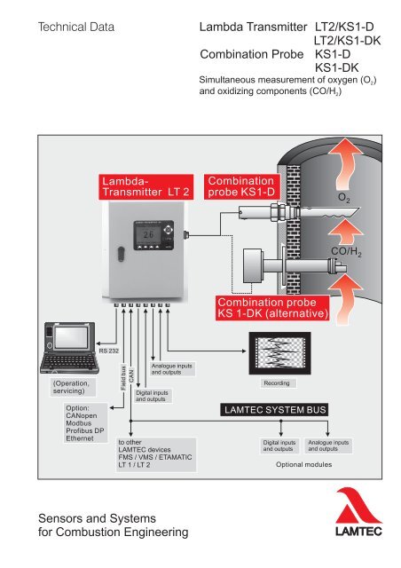
System Components<strong>Lambda</strong> <strong>Transmitter</strong> LT 2/<strong>KS1</strong>-DComponents requiredThe measuring system is available in different models.It consists of the following components- Combination probe <strong>KS1</strong>-D, alternatively <strong>KS1</strong>-DK-(1)gas extraction device (MEV)-(1)probe mount (SEA)-(1)probe connection box (SAK)- <strong>Lambda</strong> <strong>Transmitter</strong> LT 2/<strong>KS1</strong>-D, or LT 2/<strong>KS1</strong>-DKin wall mounting housing IP 65orin panel mounting housingincluding display and operating unitorinstallation plate IP00 for installation in a control cabinet(1) only necessary with <strong>KS1</strong>-DBasic structure of theLT 2 / <strong>KS1</strong>-DConnector121 2 3 4563 4Mesured gasmax. 300°C<strong>Lambda</strong> <strong>Transmitter</strong> LT 2/<strong>KS1</strong>-Dsystem housing for installation in panel 3 HE, 50 TE173x310x280mm(HxWxD)Type 657 R 1040 <strong>KS1</strong>D6Legend:123456Combination probe <strong>KS1</strong>-D, Type 656 R 2000Gas extraction device (MEV),Type 655 R 1001-R 1003Probe mount (SEA), Type 655 R 1010Half-sleeve R1¼", Type 655 R 1012or Probe connection box (SAK), Type 656 R 3025Display and operating unit, Type 657 R 0831<strong>Lambda</strong> transmitter <strong>LT2</strong>/<strong>KS1</strong>-D in wall mounting housing IP 65Type 657 R 1025<strong>KS1</strong>D, sheet steel, 400 x 300 x 150 mm (H xWxD)with display and operating unitType 657 R 08314
System Components<strong>Lambda</strong> <strong>Transmitter</strong> LT 2/<strong>KS1</strong>-D/<strong>KS1</strong>-DKBasic structure of the <strong>LT2</strong>/<strong>KS1</strong>-DKwith semi-automatic calibration3Probe connection box (SAK)5216Measured gasmax. 450 °C(840°F)4Hose connection calibrationPressure air / tes gas 1 bar1 Combination probe <strong>KS1</strong>-DKType 656 R 2030 / R 2031 / R 20322 Pre filterType 650 R 20553 Counting flangeType 655R0137 / R01384 Flange seal, Klinger Sil C-4400Type 655P42095 <strong>Lambda</strong> transmitter <strong>LT2</strong>/<strong>KS1</strong>-DKType 657R1028Outletreference airPressure reducer(to be provided bycustomer)Hose connection reference airPressure air 1 bar orreference air pump **Probe signals, absolute-, difference pressure sensorProbe heating** reference air pump is only needed, when there is no pressure air6 Display and operating unit (option)Type 6 57 R 0831Dimensional diagram <strong>KS1</strong>-DK1608014 X50Combination probe <strong>KS1</strong>-DKImmersion depth ( )656 R 2030 500 mm656 R 2031 1000 mm656 R 2032 1500 mm5
Theoretical PrinciplesMeasuring Principle<strong>Lambda</strong> <strong>Transmitter</strong> LT 2/<strong>KS1</strong>-D/<strong>KS1</strong>-DKThe combination probe <strong>KS1</strong>-D/<strong>KS1</strong>-DK consists mainly of a zirconium dioxideelectrochemical cell.It has 3 electrodesan O -sensitive platinum electrode2a CO/H -sensitive electrode made from a platinum/noble metal alloy2a platinum reference electrodeProbe principleGas inletCO/H2electrode(Pt / noble metal alloy)Referenceelectrode (Pt)U SU HZirconium oxide ceramicProtective coatingHousingO2-selectivereference electrode (Pt)Diagram showing the structure of the combination probe <strong>KS1</strong>-DThe O2measuring cell acts as an electrochemical concentration cell and generates ad.c. voltage which is dependent upon the absolute temperature T and the logarithmof the O2 concentration ratio or O2 partial pressure ratio at the reference and outer O2electrode.If the sample gas is fed to the outer electrode and a reference gas with a known O2concentration, such as air for example (20.96%), is fed to the inner electrode, if thetemperature is kept constant, this will give the logarithmic relationship, shown below,between the probe voltage US and the concentration of oxygen in the sample gas.120U (mV)Sensor100806040U s = 0,049 · T · log p (L) O2p (G) O2O 2[%] = 20,96 · 10Us0,049 T.2000 1 2 3 4 5 6 7 8 9 O (%)6Sensor characteristic U S = f (O2)
Theoretical PrinciplesMeasuring Principle<strong>Lambda</strong> <strong>Transmitter</strong> LT 2/<strong>KS1</strong>-D/<strong>KS1</strong>-DKCO/H2 - sensitive electrode Combustible components are adsorbed as oxygen molecules at theelectrode and diffuse to the "three-phase limit" formed by measuring gas,electrode and zirconium dioxide. In addition to the Nernst voltage UO2determined by the oxygen content, the combustible components presentgenerate an additional d.c. voltage U CO / H2through the sensor.The sensor voltage is the sum of the two voltages U S = U O2 + U CO/H2(Fig. 1). Even with low concentrations of oxidizing gases such as H2or CO,the mixture potential is much higher than the O2signal.The mixture potential forms very quickly, T60times of less than 2 seconds areachieved. Sensitivity to O2and combustible components can be influenced bythe temperature of the sensor. Lower sensor temperatures bring about highersensitivity to CO/H2 and lower sensitivity to O2(Fig. 2).The concentration of oxygen also influences the sensor voltage U COe.With higher O2content, the sensor voltage in the high CO range drops slightly(Fig. 3).However, the combination probe <strong>KS1</strong>-D may not be used when it is too cold orelse the oxidizing components will influence the O2measurement (falsificationof the measurement value to lower values because of oxidation of the nonburnedflue gas components on the O electrode).2Us(mV)COSensor characteristics(measured)Nernst characteristic(calculated)O (%)incompletecombustioncompletecombustionFig. 1: Characteristic on a gas burner1000800U [mV]COe60040020020 W25 W00 5000 10000 15000CO [ppm]Fig. 2: Sensor voltage UCOeas a function of sensor temperature (heat output)7
Theoretical PrinciplesMeasuring Principle<strong>Lambda</strong> <strong>Transmitter</strong> LT 2/<strong>KS1</strong>-D/<strong>KS1</strong>-DKWith higher O2 concentrations, more non-burned residue (CO/H2) oxidizesbefore it reaches the 3 phase limit. The effect of sensor voltage UCOeas afunction of the O content is shown in the graph below.21000800U [mV]COe600400200at startingpoint with0% CO9,5%O26 %O 200 2000 4000 6000 8000 10000CO [ppm]Fig. 3: Sensor voltage Uas a function of O contentCOe 2It is therefore recommended that the characteristic is calibrated specificallyfor the system with a CO reference measurement.Another indicator for non-burned residue (CO/H 2) on combustion systemsis the dynamics of the sensor signal (U S). The higher the content of nonburnedresidue, the higher the dynamics. The following figure traces therise of the sensor signal over the O2value measured with a lambda probeLS1 on a reference system (12 MW SAACKE gas burner)with a small load.700600U [mV]Sensor500400300200Signal dynamic> + 100 mV30040CO [ppm]1000small load0 1 2 3 4 5 6O ref. [%]22Application:Quick-response O2measurement combined with the detection of oxidizing fluegas components (non-burned residue) CO/H .28
Theoretical PrinciplesMeasuring Principle<strong>Lambda</strong> <strong>Transmitter</strong> LT 2/<strong>KS1</strong>-D/<strong>KS1</strong>-DK1. As a threshold control for monitoring combustion systems2. For self-adjusting burner controlBurner characteristic CO over O contentof 4 different combustion systemsMarienkrankenhausLudwigshafen (7MW)CO(ppm) Halle Walldorf (15kW)1000Characteristic U (CO) of a sensor over Ocontent of 4 different combustion systemsMarienkrankenhausLudwigshafen (7MW)U CO/H (mV) Halle Walldorf (15kW)800800600Walldorf heatingstation (3.9 MW)Käfertal power station(100 MW)700600500Walldorf heatingstation (3.9 MW)Käfertal power station(100 MW)4004003002002001000 00 2 4 6 8 10 12 O2 (%) 0 2 4 6 8 10 12 O2 (%)Fig. aFig. bThreshold controlSelf-adjusting burner controlDiagrams a) and b) show that, with a threshold voltage on all 4 systems, it ispossible reliably to detect when a CO limit of above 20 ppm in the flue gas isexceeded. The threshold control offers a simple, continuous monitoring facilityfor combustion systems and gives an alarm message if the burnercharacteristic threatens to enter the range of an unacceptably high COemission, e.g. from going out of adjustment or clogging.Diagram b) shows that burner control is possible.The operating point of the burner control is no longer fixed or determined bya characteristic field that is programmed in once, but is continuouslydetermined and re-set interactively during operation.To do this the fuel/air mixture is changed in the direction of a lower lambdavalue (less air, more fuel) until the combination probe <strong>KS1</strong>-D/<strong>KS1</strong>-DK showsthe start of incomplete combustion with a strong signal rise from theCO/H2-selective electrode and dynamics. From this point on, the fuel/airmixture is now changed back a little in the direction of a higherlambda value (more air, less fuel).The optimal operating point is found. This process is repeated in cycles so thatthe optimal operating points are always maintained even in unfavourableweather- and system-related conditions.If the burner characteristic shifts during operation and the combination probe<strong>KS1</strong>-D/<strong>KS1</strong>-DK therefore detects non-burned residue (CO/H 2), the operatingpoint is immediately moved in the direction of a higher lambda value(more air, less fuel). If the operating point is re-established from time to time,using the method described here, then slow changes of the burnercharacteristic can be tracked.9
Options<strong>Lambda</strong> <strong>Transmitter</strong> LT 2/<strong>KS1</strong>-D/<strong>KS1</strong>-DK- Display and operating unit--Measurement of flue gas and intake temperature and calculation ofcombustion efficiencyLoad-dependent and fuel-specific limit values/limit curves,Limit curve 1Vol.%O 2 Fuel 15(curve 5)4Limit curves (default setting) with parameters set to undershootPossible combinations:either321000x204x 2 fuels with 4 limit curves / limit values per fuel 4 fuels with 2 limit curves / limit values per fuelx40 60 80 100x8 12 16x20Limit curve 2Fuel 1(curve 7)Burner load [%]Load spec. [mA]10------1...4 analogue outputs (0/4...20 mA, 0....10 V) max. 2 potential-free(output 1 and 2) max. potential difference + 20 Vcan be configured in any way- d.c. 0/4...20 mA, load 0...600 W- d.c. voltage 0...10 V, load > 10 kWRelay module for digital outputs with 6 relays (1 change-over contact) foroutputting operating, limit value and status messages,breaking capacity 230 V a.c., 4 A1...3 analogue inputs(1 analogue input with <strong>LT2</strong>/<strong>KS1</strong>-DK)Type 657 R 1028/R 1032can be configured with measuring cards in any way,e.g. for temperature sensor, other pressure sensors,standard signals, etc.;max. 2 of these potential-freemax. potential difference + 20 VField bus interface for- Profibus DP- Modbus- CANopen- EthernetWindows-based remote display software for PCCalculation and display of CO concentration,fuel-referenced, computed from the measured O value andthe CO max. value
<strong>Technical</strong> <strong>Data</strong><strong>Lambda</strong> <strong>Transmitter</strong> LT 2/<strong>KS1</strong>-D/<strong>KS1</strong>-DKModel: Wall mounting housing Wall mounting housing Installation plate Panel-mountingwith reference airhousing<strong>LT2</strong> with <strong>KS1</strong>-D Type 657 R 1025<strong>KS1</strong>D pump option Type 657 R 1030<strong>KS1</strong>D Type657R1040<strong>KS1</strong>D<strong>LT2</strong> with <strong>KS1</strong>-DK Type 657 R 1028 Type 657 R 1060 Type 657 R 1032 -----------------------Housing:Powder-coated Powder-coated Sheet steel 3 HE / 50TEsheet steel sheet steel mounting plate panel mountingmounting housing mounting housing housingDIN 40050 protection class IP 65 IP 65 IP 00 IP 20front IP 40Dimensions (hxwxd) mm 400 x 300 x 150 500 x 300 x 200 350 x 258 x 131.5 173 x 310 x 270Colour Grey RAL 7032 Grey RAL 7032 ___ Metallic silver(anodizedaluminium),grey controlsWeight approx. 10 kg approx. 13 kg approx. 6 kg approx. 5 kgplusdisplay and control unit approx. 0,5 kg approx. 0,5 kg approx. 0,5 kg ___Ambient temperature:OperationTransport and storage:Auxiliary voltage:Power consumption:Display:-20°C ...+60°C (-4°F ...+140°F)-40°C ...+85°C (-40°F ...+185°F)230 V a.c. and 115 V a.c.+10% / -15 %, 48 Hz...62 HzTypically 50 VA briefly 150 VA (probe heating-up phase)To be used only in a grounded power line network!LCD graphic display 100 x 80 mm (w x h)in LT 2 wall-mounted housing type 6 57 R 1025<strong>KS1</strong>D and R 1029<strong>KS1</strong>D optionalin panel installation case type 6 57 R 1040<strong>KS1</strong>D standardDisplay and operating unit type 6 57 R 0831(version installation in a case)Display and operating unit type 6 57 R 0831T(version panel installatin for <strong>LT2</strong> on installation plate)Resolution: O 2 : 0,1 vol.% O2 in the range 0...18 vol.% O21 vol.% O2 in the range 18...30 vol.% O2CO : 1 ppmeMeasuring accuracy:O2: +/- 5% of measurement valuewith comb. probe <strong>KS1</strong>-D/DK not better than +/-0,3 vol. % O2after prior calibration underCO e : +/- 25% of measurement value not better than+/- 10 ppm after prior calibration under system conditionswith a CO reference measurementMeasuring range 0...100 ppm : max. 10 ppmin flue gases of natural gas combustion after calibration undersystem conditions with a CO reference measurementSetting time (60% time):Time to readiness foroperation with <strong>KS1</strong>-D/DK:O2: T 60 < 10 sCO : T 60 < 2 seApprox. 10 minutes after "POWER ON"11
<strong>Technical</strong> <strong>Data</strong><strong>Lambda</strong> <strong>Transmitter</strong> LT 2/<strong>KS1</strong>-D/<strong>KS1</strong>-DKAnalogue outputs:Monitor output 0...2,55 V d.c., load >10 k W, < 100 nFAccuracy:2 % of the measurement value, not better than 0,2 vol. % OResolution:10 mVDefault setting 0...2,55 V d.c. ^ 0..25,5 vol.% OWith DIP switches can be switched toProbe voltage U-O 0...2,55 V d.c. ^ 0...255mV U-O22 221...4 current/voltage outputs 2 standard 3...4 option- Direct current 0/4...20 mALoad 0...600 W- D.c. voltage0...10 VLoad> 10 kWwith reference to device potential (potential isolation optional)Default setting: 0...10 vol.% O ^ 4...20 mA 0...1000ppm COe ^ 4...20 mAResolution:Analogue inputs:20,1 vol.% O2Measuring range and physical quantities can be configuredoptional 2...4via plug-in cards on <strong>LT2</strong> power pack electronics- Universal module for potentiometer0...5 kW6 57 P 6000- Universal module for current0/4...20 mA6 57 R 0052- Universal module for voltage0/2...10V6 57 P 6005- Temperature input for PT 100 sensor657 R 0890Accuracy:0,05 % of measurement value, not better than 0,1 vol.% O2ControlsWall mounting housingMultifunction keyMaintenance switch and2 rows of 6 LEDsDisplay and operating unitwith LCD graphic display (option)Remote display software (option)Panel mountingDisplay and operating unit withLCD graphic displayInterfaces:LAMTEC SYSTEM BUSRS 232 only in conjun. with interface module 6 63 P 0600Field bus connection:Optional for the following systemsProfibus DP (Siemens)ModbusCANopenEthernet12
<strong>Technical</strong> <strong>Data</strong><strong>Lambda</strong> <strong>Transmitter</strong> LT 2/<strong>KS1</strong>-D/<strong>KS1</strong>-DKDigital outputs:1 standard + 6 optional1 relay output 0...230 V a.c., 2A0... 42 V d.c., 3ACollective fault messageoptional:Relay card with 6 relays (1 change-over contact)Breaking capacity 0...230 V a.c., 4A0...48 V d.c., 3ADigital inputs:8 inputs - freely configurableFactory settings: 24 V DC, referenced to instrument potentialCan be switched via jumper to floating, for external voltagesource.Cold start delay:Conformity with the followingEuropean GuidelinesAutomatic cold start delay,10 minutes89 / 336 / EEC Electromagnetic compatibility73 / 23 / EEC Electrical equipment within specific voltage limits13
<strong>Technical</strong> <strong>Data</strong>Combination Probe <strong>KS1</strong>-D/<strong>KS1</strong>-DKMeasuring rangeO :2CO e:0...18 vol.% O2with limit 0...21 vol.% O0...10,000 ppm COe2Measuring accuracyO: 2 +/-5%ofmeasurement valuenot better than +/- 0,30 vol.%after prior calibration under system conditions with aCO reference measurement by natural gas combustionCO e:+/- 25 % of measurement valuenot better than +/- 10 ppm after prior calibration undersystem conditions with a CO reference measurementMeasuring range 0...100 ppm : max. 10 ppmError influences:Cross-sensitivity:Permissible fuelsPermissible continuousoff-gas temperatureService lifeProbe output voltage0,01 to 21 vol. % O20...10.000 ppmInternal probe resistance RIin air 20°C and 22 W heat outputHeat outputIsolating resistancebetween heating andprobe connectionTemperature, other non-burned hydrocarbonsto SO , NH , NO, propane, aromatic hydrocarbons2 3Residue-free , gaseoushydrocarbons and lightheating oil<strong>KS1</strong>-D < 300° C ( < 570° F)<strong>KS1</strong>-DK < 450° C ( < 840° F)> 2 yearswith heating oil EL and natural gas150...-20 mV0...800 mV15...25 W20...25 Wdepending on design and temperature of the gas measured>13MW14
<strong>Technical</strong> <strong>Data</strong>Combination Probe <strong>KS1</strong>-D/<strong>KS1</strong>-DKApplication conditions:<strong>KS1</strong>-D<strong>KS1</strong>-DKType 656 R 2000 656 R 2010 656 R 2030...R 2032(order code)Permissiblecontinuous off-gastemperatureElectricalconnectionReference air:< 300 °C < 300 °C < 450 °C(
Dimensional DiagramCombination Probe <strong>KS1</strong>-DCombination probe SK1-DType 656 R 2000see table2066185147M4SW7 22R1 ¼ “SW 50 351 2 3Part_______________________________________________________________Nr. Ordering details1 655 R 1001 Measured gas sampling device (MEV)150 mm long655 R 1002 as above, 300 mm long655 R 1003 as above, 450 mm long_______________________________________________________________655 R 1004 as above, 1000 mm long2 655 R 1010 Probe mount (SEA)_______________________________________________________________Male coupling, R 1¼"3 656 R 2000 Combination probe <strong>KS1</strong>-D up to 300°Coff-gas temperatureCombination probe <strong>KS1</strong>-DType 656 R 2010SW 22ThreadM 18 x 1,515Supply line2m1152030Electrical connection:Type 656 R 2000/R 2010 -->Pin connectionsTeflon cable, 5-wire with interlockingconnector, length 2m32 41 51=CO/H/O Signal +, (black)2= CO/H Signal -, (grey)3= Heating (white)4= Heating (white)5=O Signal -, (blue)Type 656 R 2001/R 2011-->glass-insulated nickel cable,length 2m with conductor sleeves16
Dimensional DiagramCombination Probe <strong>KS1</strong>-DKor 1500or 10005005 1 Filter insert4 1 <strong>KS1</strong>-D probe3 1 Connection box with valves2 1 Housing 1.45711 1 Probe head 1.4571Element Qty. Description Standard Material17
Dimensional Diagram<strong>Lambda</strong> <strong>Transmitter</strong> LT 2/<strong>KS1</strong>-D/ /<strong>KS1</strong>-DKWall Mounting Housing657 R 1025<strong>KS1</strong>D / 657 R 1060Type 657 R 1025<strong>KS1</strong>D55453522.535.5300175 306 15085LAMBDA TRANSMITTER <strong>LT2</strong>115ENTERLAMTEC400Type 657 R 1060 with integ. reference air pump554535300175 3022.535.52006180LAMBDA TRANSMITTER <strong>LT2</strong>ENTER115500LAMTEC18
F20,4ATF31ATF41,25ATF54ATDimensional Diagram<strong>Lambda</strong> <strong>Transmitter</strong> LT 2/<strong>KS1</strong>-DPanel Mounting Housing657 R 1040<strong>KS1</strong>D310LAMBDA TRANSMITTER <strong>LT2</strong>KREMOTE132.5 (HE)57.110.5ENTER172.57.5LAMTEC254 (50TE)292.4PG connections26375 74 73 72 71 64 63 62 61 60 45 44 43 42 26 25 24 23 22 21 20 19 18 17 16 15 14 13 12 1169 68 67 66 6549 48 47 46 36 35 34 33 32 313 2 1F6X5 X12 X7 0,315ATEN PX1X6X8X11230VX13X15115VLBR105X9LED2LED1X101AT/3BR102BR101BR10BR10BR107BR104F16Ringkerntrafo253Panel mounting cut out dimensions 6.5276 x 13557.1135398.2276292.419
Dimensional Diagram<strong>Lambda</strong> <strong>Transmitter</strong> LT 2/<strong>KS1</strong>-Don installation plate657 R 1030<strong>KS1</strong>DAnalogueoutputmoduleAnalogueoutputmoduleAnalogueoutputmoduleAnalogueoutputmoduleDimensional diagram of probeconnection boxType 656 R 302520Height: 40 mmProtection class: IP 65
Connection Diagram<strong>Lambda</strong> <strong>Transmitter</strong> LT 2/<strong>KS1</strong>-D<strong>Lambda</strong>-<strong>Transmitter</strong> LT 2Analogue outputs3 and 40/4…20 mA0/2…10 V(option)* on processorboard* Module 4* Module 3* Module 2* Module 1(+)(-)(+)(-)(+)(-)(+)(-)4948474645444342Output 4 Analogue output card notfloating 6 57 R 0050Output 3 Analogue output card floatingmax. possible elec. potential + 20V(only possible for output 1 and 2)Output 2 6 57 R 0051Default setting 0...1000 ppm COe ^ 4...20 mAOutput 1Default setting 0...10 vol.% O ^ 4...20 mAMonitor output0…2.5 V d.c.(+)switching O , U- (only 0 mV) (-)2O 2>3231e.g. for connecting a multimeter forservicing purposes Ri > 10 kWAnaloguemeasuring inputsnormal signals0/4…20 mA0…10 Vtemperature,pressure,(option)Measuringcard 4not for DKMeasuringcard 3not for DKMeasuringcard 226252423222120191817161524 V d.c. voltage supply for transmitter+ signal input- signal inputGND24 V d.c. voltage supply for transmitter+ signal input- signal inputGND24 V d.c. voltage supply for transmitter+ signal input- signal inputGND222Type 663 P 0660-200mV...+1000mVMeasuringcard 1used internally forCOesignalRelay output 10...42 V d.c.3A0...230 V a.c.2A321e.g. collective fault message(can be configured in any way)default setting zero signal current principlePE= EarthF1 T1AT2A/ 250 V [230 V]/250V[115V]NL= Neutral conductor= Phase 230 / 115 V, 48…62 HzConnecting powertyp. 50 VAbriefly (probe heating phase) approx. 150 VATo be used only in a grounded power line network!* Other levels / signal inputs are also possible depending on the measuring cardMaximum 2 of these potential-free (measuring cards 1 and 2); maximum possible potentialdifference + 20 V.2Maximum overall current load for all 4 measuring cards together 80 mA21
Connection Diagram<strong>Lambda</strong> <strong>Transmitter</strong> LT 2/<strong>KS1</strong>-D<strong>Lambda</strong>-<strong>Transmitter</strong> LT 2LAMTEC SYSTEM BUS(CAN-Bus)floating7574737271CAN LowCAN Highnot connectednot connectedGNDDigital inputs24 V, approx. 6 mAJumper BR 106, BR 107 onpower electronics1 - 2 - with ref. to potential(below) difference2 - 3 - floating for(above) external voltagesource+24 V69686766656463626160Fuel 4Fuel 3Fuel 2 (Gas)Maintenance ON/OFFPID-regulator OFFRelease calibrationReset limit valuesReset faults / warningsInput 8Input 7Input 6Input 5Input 4Input 3Input 2Input 1GND+24 V d.c.-Probe connection<strong>KS1</strong>-D3635Probe heatingProbe heatingnote cable cross-sectionbelow 20 m = 1,5 mmup to 50 m = 2,5 mm(+)34CO/H2/O2 probe signal +( - )33O 2probe signal -on measuring card 1( - )12CO/H2 probe signal -Connection diagram for probeconnection box 656 R 3025Pin connections32 41 51=Signal+,(black)2 = Signal -, CO/H (grey)3 = Heating (white)4 = Heating (white)5 = Signal -, O (blue)Screen = housing22
Connection Diagram<strong>Lambda</strong> <strong>Transmitter</strong> LT 2/<strong>KS1</strong>-DRelay module for digital outputs(option)<strong>Lambda</strong> - <strong>Transmitter</strong> LT 2Relay module 657 R 0857Terminal strip x2d 6181617Output 7Relayoutputs2-7d 5d 4151314121011Output 6Output 5Max.230 V a.c. 4 A48V d.c. 3Ad 3978Output 4d 2645Output 3d 1312Output 2Interface moduleRS 232 only in conjunction withremote display software-657R1101RS 422 - 6 63 P 0500Connector for 25 PINinterface module23
Connection Diagram<strong>Lambda</strong> <strong>Transmitter</strong> LT 2/<strong>KS1</strong>-DKCombination Probe <strong>KS1</strong>-DK(semi-automatic calibration)<strong>Lambda</strong>-<strong>Transmitter</strong> LT 2/<strong>KS1</strong>-DKDigital inputs24 V, approx. 6 mAJumper BR 106, BR 107 onpower electronics1 - 2 - with ref. to potential(below) difference2 - 3 - floating for(above) external voltagesource+24 VFuel 469Input 8Fuel 368Input 7Fuel 2 (Gas)67Input 6Maintenance ON/OFF66Input 5PID-regulator OFF65Input 4Release calibration Input 364Reset limit values Input 263Reset faults / warnings Input16261 GND60<strong>KS1</strong>-DK+24 V DC-Probe connectionLS2/<strong>KS1</strong>-DKHeating36353635ProbeOutletreference airCO/H2/O2 probe signal +O 2probe signal -CO/H2 probe signal -Measuringcard 4343312 1226252423343326252423AbsolutepressuresensorThrottleHose connection,reference air(compressed air,approx. 1 bar orreference air pump)Measuringcard 32221201922212019DifferentialpressuresensorThrottleShut-off valveHose connection,calibrationcompressed air /test gas 1 barConnector for 25 PINinterface modulesInterface modulesRS 232 Only in conjunction withremote display software - 6 57 R 1101RS 422 - 6 63 P 050024
Ordering DetailsCombination Probe <strong>KS1</strong>-D/<strong>KS1</strong>-DK<strong>Lambda</strong> <strong>Transmitter</strong> LT 2/<strong>KS1</strong>-D/<strong>KS1</strong>-DKCombination probe KS 1-D for simultaneous measurement of oxygen (O2) and non-burned residue (CO/H2)- with connecting cableDesignation / TypeCombination probe KS 1-D with PTFE connecting cable (up to 300 °C), 2 m long - standardCombination probe KS 1-D 656 R 2000, without housingOrder Code6 56 R 20006 56 R 2010Combination probe KS 1-DK (up to 450°C / 840°F)- with test gas connection for semi-automatic calibrationDesignation / TypeOrder CodeCombination probe KS 1-DK, immersion depth from flange 500 mm 6 56 R 2030Combination probe KS 1-DK, immersion depth from flange 1.000 mm 6 56 R 2031Combination probe KS 1-DK, immersion depth from flange 1.500 mm 6 56 R 20321)Other installation lengths on applicationAccessories for combination probe KS 1-DDesignation / TypeOrder CodeMeasured gas sampling device (MEV), 150 mm long 6 55 R 1001Measured gas sampling device (MEV), 300 mm long 6 55 R 1002Measured gas sampling device (MEV), 450 mm long 6 55 R 1003Measured gas sampling device (MEV), 1,000 mm long 6 55 R 1004Probe mount (SEA) - male coupling R 1¼ " 6 55 R 1010Probe mount (SEA) - flange fastening DN 32 PN 6, material, yellow chromated steel 6 55 R 1040Half sleeve R 1¼ " DIN 2986 for SEA 655 R 1010 6 55 R 1012Extension for probe connecting cable KS 1-D, 2 m long 6 56 R 3006Extension for probe connecting cable KS 1-D, 5 m long 6 56 R 3007Extension for probe connecting cable KS 1-D, 10 m long 6 56 R 3008Extension for probe connecting cable KS 1-D, 20 m long 6 56 R 3009Probe connection box (SAK) for KS 1-D 6 56 R 3025Accessories for combination probe KS 1-DKDesignation / TypeOrder CodeMating flange DN 65 PN 6, material: special steel 1.4571 (V4A) 6 55 R 0137Mating flange DN 65 PN 6, material: steel, KTF coating, black 6 55 R 0138Flange seal DN 65 PN 6, material: Klinger Sil C-4400 6 55 P 4209Wall mounting housing IP 65 with display and control unit - excluding probeDesignation / TypeOrder Code<strong>Lambda</strong> transmitter LT 2/<strong>KS1</strong>-D6 57 R 1025KS 1D<strong>Lambda</strong> transmitter LT 2/<strong>KS1</strong>-DK 6 57 R 1028Installation plate IP 00 excluding display and control unit - excluding probeDesignation / TypeOrder Code <strong>Lambda</strong> transmitter LT 2/<strong>KS1</strong>-D on installation plate for installation in control cabinet6 57 R 1030<strong>KS1</strong>D <strong>Lambda</strong> transmitter LT 2/<strong>KS1</strong>-DK on installation plate for installation in control cabinet 6 57 R 1032Panel mounting housing 3HE/50TE with display and control unit - excluding probeDesignation / Type<strong>Lambda</strong> transmitter LT 2/KS 1-D (prepared for panel mounting)Order Code6 57 R 1040<strong>KS1</strong>D25
Ordering DetailsCombination Probe <strong>KS1</strong>-D/<strong>KS1</strong>-DK<strong>Lambda</strong> <strong>Transmitter</strong> LT 2/<strong>KS1</strong>-D/<strong>KS1</strong>-DKDisplay and controlDesignation / TypeOrder CodeDisplay and control unit for wall mounting case 6 57 R 0831Display and control unit for installation plate for mounting in the cabinet door6 57 R 1031 TO2 remote display 0...25.5% vol. 96x48x135 mm (wxhxl), 230 v a.c. 6 57 R 1830O2 remote display 0...25.5% vol. 96x48x135 mm (wxhxl), 24 v d.c. 6 57 R 1831Software expansion for LT 1, remote control of other LTs via LSB 6 57 R 0603Remote display software including interface module 663 P 0600 6 57 R 1101Remote display software (CD only, no interface module) 6 57 R 1102Interface module RS422 instead of interface module RS232, extra price 6 63 R 9002Interface module RS 422/485 6 63 P 0501Serial connecting cable, 9-pole, Sub-D, socket-socket, 10 m long 6 63 R 0100Extension for serial connecting cable, 9-pole, Sub-D, socket-plug, 10 m long(can be extended in total to max. 40 m) 6 63 R 0101USB on serial adapter for WIN2000/XP 6 63 R 9003Off-gas temperature measurement and efficiency calculationDesignation / TypeOrder CodeCalculation of combustion efficiency,including 2 temperature inputs for PT100 temperature sensor 6 57 R 0895Calculation of combustion efficiency for DKincluding 2 temperature inputs for PT100 temperature sensor6 57 R 0895 KTemperature input for PT 100, e.g. for measuring flue gas temperature 6 57 R 0890Temperature sensor PT 100, 150 mm long 6 57 R 0897Temperature sensor PT 100, 250 mm long 6 57 R 0891Temperature sensor PT 100 / IP 65, as external sensor -30 °C to +80 °C (-18...180°F) 6 52 R 0115Immersion sleeve for PT 100, installation length 150 mm, material: special steel 6 52 R 0113Immersion sleeve for PT 100, installation length 250 mm, material: special steel 6 52 R 0114CO calculation2Designation / TypeOrder CodeCalculation of CO concentration 6 57 R 0910Limit valuesDesignation / TypeOrder CodeLoad-dependent and fuel-specific limit curves/limit values incl. analogue input card657 R 0052 and 1 relay module 660 R 0017 6 57 R 0922Relay module with 6 signalling relays (1 change-over contact) for outputting operatingand status messages, for installation in LT 2 6 57 R 0857O -regulation2Designation / TypeOrder CodeIntegrated PID regulator for O , temperature, pressure regulation, etc. 6 57 R 0120Field bus connectionDesignation / TypeBUS connection for Profibus DPBUS connection for CANOpenBUS connection for Modbus (RTU)BUS connection for Ethernet (Modbus TCP)Order Code6 63 R 0401LT6 63 R 0402LT6 63 R 0403LT6 63 R 0406LTReference air pumpDesignation / TypeOrder CodeReference air pump incorporated in <strong>LT2</strong>/<strong>KS1</strong>-DK (wall mounting) 6 57 R 1060Reference air pump in external housing 6 57 R 106126
Ordering DetailsCombination Probe <strong>KS1</strong>-D/<strong>KS1</strong>-DK<strong>Lambda</strong> <strong>Transmitter</strong> LT 2/<strong>KS1</strong>-D/<strong>KS1</strong>-DKOptions and accessoriesDesignation / TypeOrder CodeAnalogue output card 0/4...20 mA, 0...10 V 6 57 R 0050Analogue output card 0/4...20 mA, 0...10 V, potential-free, max. potential difference + 20 V(outputs 1 and 2 only) 6 57 R 0051Extra price for potential-free analogue output 1, max. potential difference + 20 V 6 57 R 0054Analogue input card, potentiometer 6 57 P 6000Analogue input card 0/4...20 mA 6 63 P 6001Analogue input card 0/4...20 mA with +24 V d.c. supply for transmitter 6 63 P 6002Analogue input card 0/2...10 V 6 57 P 6005Probe simulator 6 55 R 1030Simultaneous measurement of oxygen (O2) and non-burned residue (CO/H2)in wall mounting housing, IP 54, for measured gas temperatures up to 300 °C (570°F)Designation / TypeOrder Code1 combination probe KS 1-D with PTFE connecting cable (up to 300 °C), 2 m long - standard 6 56 R 20001 measured gas sampling device (MEV), 150 mm long 6 55 R 10011 probe mount (SEA), male coupling R 1¼ " 6 55 R 10101 <strong>Lambda</strong> transmitter LT 2/<strong>KS1</strong>-D 657R1025<strong>KS1</strong>DSimultaneous measurement of oxygen (O2) and non-burned residue (CO/H2)in wall mounting housing, IP 65, for measured gas temperatures up to 450 °C (840°F)Designation / TypeOrder Code1 Combination probe KS 1-DK, immersion depth from flange 500 mm 6 56 R 20301 <strong>Lambda</strong> transmitter LT 2-DK incl. display and control unit 6 57 R 10281 Reference air pump integrated in Lt2 6 57 R 10601 Mating flange DN 65 PN6, material steel, KTF coating, black 6 55 R 01371 Flange seal for flange DN 65 PN6, Klinger Sil C - 4400 6 55 P 420927
LAMTEC Meß- und Regeltechnikfür Feuerungen GmbH & Co KGImpexstraße 5D-69190 WalldorfTelefon (+49) 06227 / 6052-0Telefax (+49) 06227 / 6052-57Internet: http://www.<strong>lamtec</strong>.deE-mail: info@<strong>lamtec</strong>.deLAMTEC Leipzig GmbH & Co KGSchlesierstraße 55D-04299 LeipzigTelefon (+49) 0341 / 863294-00Telefax (+49) 0341 / 863294-10Brochure-No.DLT3007-07-aE-0058Printed in Germany


