Designing a dielectric cell
Designing a dielectric cell
Designing a dielectric cell
- No tags were found...

Create successful ePaper yourself
Turn your PDF publications into a flip-book with our unique Google optimized e-Paper software.
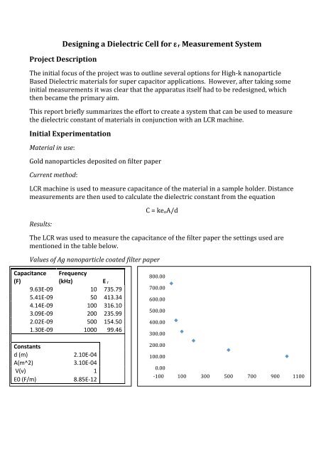
<strong>Designing</strong> a Dielectric Cell for ε r Measurement System Project Description The initial focus of the project was to outline several options for High-‐k nanoparticle Based Dielectric materials for super capacitor applications. However, after taking some initial measurements it was clear that the apparatus itself had to be redesigned, which then became the primary aim. This report briefly summarizes the effort to create a system that can be used to measure the <strong>dielectric</strong> constant of materials in conjunction with an LCR machine. Initial Experimentation Material in use: Gold nanoparticles deposited on filter paper Current method: LCR machine is used to measure capacitance of the material in a sample holder. Distance measurements are then used to calculate the <strong>dielectric</strong> constant from the equation Results: C = keoA/d The LCR was used to measure the capacitance of the filter paper the settings used are mentioned in the table below. Values of Ag nanoparticle coated filter paper Capacitance (F) Frequency (kHz) E r 9.63E-‐09 10 735.79 5.41E-‐09 50 413.34 4.14E-‐09 100 316.10 3.09E-‐09 200 235.99 2.02E-‐09 500 154.50 The values for th 1.30E-‐09 1000 99.46 800.00 700.00 600.00 500.00 400.00 300.00 Constants d (m) A(m^2) V(v) E0 (F/m) 2.10E-‐04 3.10E-‐04 1 8.85E-‐12 200.00 100.00 0.00 -‐100 100 300 500 700 900 1100
Values for regular paper Regular Paper Capacitance (F) Frequency (kHz) Er 3.91E-‐09 10 298.90 3.01E-‐09 50 229.95 2.46E-‐09 100 187.98 1.84E-‐09 200 140.35 9.37E-‐10 500 71.62 4.40E-‐10 1000 33.64 350.00 300.00 250.00 200.00 150.00 100.00 Constants d (m) A(m^2) V(v) E0 (F/m) 2.10E-‐04 3.10E-‐04 1 8.85E-‐12 50.00 0.00 0 200 400 600 800 1000 1200 Apparatus Re-Design Evolution From the previously outlined experiment the apparatus was deemed inappropriate for rigorous testing under different conditions, thus the effort to design a new set-‐up was taken up First Design Current design of the <strong>dielectric</strong> <strong>cell</strong> Main disadvantages of the design: -‐Poor contact between electrodes -‐Cannot measure capacitor thickness -‐Movement of sample during experiment
Redesign: Comments: Disadvantages: -‐ Too complex -‐ Both plates need not move -‐ Electrical connections are a problem -‐ Thickness measurement not included Advantages: -‐Guard electrode to stop fringe fields -‐Tight sample hold, good contact -‐Stable -‐Easy measurement of thickness
Second Design Initial CAD designs for the system Note: A new part was added for use as a liquid test <strong>cell</strong>
Comments - Add facility for temperature variation (heating) - Remove excess rods - Add a fixed support for the micrometer - Add facility for BNC connectors - Fix the upper guard electrode to the upper electrode - Electrical connections need to be finalized - Model needs to be made accurately with measurements - Define material requirements - Liquid <strong>cell</strong> portion Third Design Comments - Make sure the dimensions of the insulating cover allow to fit easily - Include raw dimensions of the ceramic insulator for the cover - Edit the guard electrodes so they accommodate a range of samples - Consider the Options for insulating the upper electrodes from the rest of the assembly - Thermal coating for upper electrode/shaft contact o Glue o Ceramic o Thermal tape (wrapping it around) - Make exact measurement based drawings for the individual parts matched to their
threaded standards - Reduce the rods to the new welded design - Set width to 1.4 cm for supporting rods - Decide what thread standards are needed for the various parts Final Design
Apparatus Manufacture Stage This section includes an overview of the individual parts comprising the final system. Technical specifications and design notes are also mentioned, along with images of the original and final parts. Basic Overall Design Insulation Cover -‐ Material: Ceramic should be able to handle 400 degrees -‐ Split into exact half cylinders, the band clamp will there to secure the setting during heating Raw material used: Cool dried clay, cut and drilled to size Note: band clamp was removed as it was deemed unnecessary
Main Shaft Holder -‐ Material: Brass -‐ Thread Standard: M14 X (1-‐1.25) (Female to the Main shafts male) Main Shaft -‐ Material: Brass -‐ Thread Standard: M14 X (1-‐1.25) (Female to the Main Shaft Holder) Note: A hanger was added to the main shaft holder to free the main shaft from the upper guard electrode, making it easier to lower the upper electrode accurately (see above image)
Ceramic ring for upper electrode plate -‐ Material: Ceramic Note: The manufacture of this ring was dropped in favor for a circular ring of flexible mica Upper Electrode plate -‐ Material: Brass
Lower Electrode plate Technical details: -‐ Material: Brass -‐ Thread Standard: M2.2 X 0.45 (Can be adjusted to M3 X 0.5, Female to be screwed into the base, the horizontal bore as in image) -‐ The thinner portion of the cylinders diameter is 14mm Note: The design was slightly altered from the original to include: -‐ The lower portion of the electrode was designed to accommodate a certain amount of movement to allow complete fit with the upper electrode surface (nut bolt fixture) -‐ The electrode is isolated from the base using thermal tape and flexible mica washers -‐ There are two electrical connections, one for the heater (isolated) and one for measurement (taken from the base of the device)
Base -‐ Material: Stainless Steel -‐ Note the legs can be cylindrical with a leather/rubber pads Note: The main faceplate was included with the base design and was used in place of the two front legs Main Shaft Support -‐ Material: Stainless steel -‐ Thread Standard: M8 X 1.25 (Male to be bolted into the base) -‐ The bend mustn't be bigger/smaller than that shown in diagram + exactly 90 degrees -‐ Inside arc length -‐ 21.2mm -‐ Overall length -‐ 105.1mm (unbent) -‐ Total height -‐ 82.3 mm Note: Due to issues with scheduling the welding process, and to allow for a more flexible assembly
Micrometer Rod -‐ Material: Stainless steel -‐ Thread Standard: M6 X 1 (Male to be bolted into the base) -‐ Note: (Needs to be grooved at regular intervals for micrometer z motion) Guard Electrodes -‐ Material: Stainless steel
LOWER PRIORITY PARTS: Liquid sample Container - Materials: o Green = Teflon o Silver = Stainless Steel/Brass o Dark Green = plug (insertion of liquid via syringe) Liquid sample Guard Electrode -‐ Material: Stainless Steel
Front Panel -‐ Material: Stainless Steel Note: Faceplate was incorporated into the overall base design
Apparatus Instructions The following are suggested instructions for a simple temperature dependant measurement of <strong>dielectric</strong> constant of a solid material. 1. Thickness measurement: Make sure the main shaft is fully tightened and the electrodes are in full contact 2. Lower the micrometer so the measuring tip is flat with the shaft surface, and take a measurement 3. Fully retract the micrometer 4. Sample Set up: Remove the Upper electrode connector 5. Unscrew the main shaft for the Upper Electrode 6. Secure the upper guard electrode on the hinges below the main shaft holder 7. Place sample on the lower electrode 8. Place the Lower Guard electrode around the lower electrode 9. Screw the Upper electrode shut ensuring the sample is within the area of the electrodes 10. Make sure the lower guard electrode does not touch the lower electrode 11. Release the upper guard electrode from the hinges and place it on the grooves of the lower guard electrode 12. Reconnect the upper electrode contact 13. Connect the BNC cables from the LCRs output (IH,PH,IL and PL contacts of the LCR machine respectivley) to the Upper and Lower Electrode connection points on the faceplate of the apparatus14. Program the LCR for desired measurement and execute 15. Heating the Sample: Place the ceramic insulation chamber around the electrode assembly
16. Connect the thermocouple meter and the heater connection to the dedicated variac 17. Slowly increment the voltage until the desired temperature is reached on the thermocouple meter 18. Repeat step 14 to take readings # The area of both electrode surfaces is 490.87 mm 2 (from r = 12.5mm)
Testing for Electrical Measurement (No Heating) BNC cables were designed to be compatible with the Quadtech 1920 Precision LCR meter. The cable designed was based on a circuit diagram taken from the component measurement accessory of the LCR machine (see image below). Key: IL PL PH IH G Current Low Potential Low Potential High Current High Ground Confirmation of the electrical continuity of the electrodes and isolation of the base was confirmed with a multimeter. The LCR was used to take several measurements successfully. Heater Testing The apparatus was connected to a voltage variac via 3.5mm audio jack for a simple and safe connection. The voltage was stepped up slowly from 0 to 50 volts while the temperature was monitored by the onboard thermocouple (black lead as seen below)
Future Additions to Apparatus As mentioned in the design evolution section of the report there are several additions to be made to the device for different applications. This section will outline the design for those accessories. 1. Measuring the <strong>dielectric</strong> constants for liquid materials: These parts would be required in order to take measurements on liquid samples. The materials to be used are mentioned in the design evolution section of the report 2. Measuring the <strong>dielectric</strong> constants for powders/composites For powdered samples the situation is a little more complex. Premade pellets cannot be used as they would be crushed by the electrodes upon contact, and their size most probably will be too small. The remaining option would be to create a small pellet maker (similar to the above liquid accessory) designed specifically for the apparatus where by the diameter would be the same as that of the electrodes. The entire pellet maker assembly would then be inserted between the electrodes to take a measurement (see the diagram below)
Finalized Apparatus Image Gallery