The LINOS Laseroptics and Lenses - Qioptiq Q-Shop
The LINOS Laseroptics and Lenses - Qioptiq Q-Shop
The LINOS Laseroptics and Lenses - Qioptiq Q-Shop
- No tags were found...

Create successful ePaper yourself
Turn your PDF publications into a flip-book with our unique Google optimized e-Paper software.
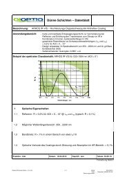
Singlets AchromatsF-<strong>The</strong>ta-Ronar <strong>Lenses</strong> 1030/1064 nm<strong>The</strong> following is valid for the overviewtables at the bottom:••<strong>The</strong> entrance beam diameter (beam-Ø)refers to the intensity 1/e 2 at Gaussianillumination. <strong>The</strong> image spot diameter(spot-Ø) refers to the intensity 1/e 2 atGaussian illumination. It can becalculated by the formula:Spot-Ø = 1.83 x λ x EFL / beam-ØSpot-Ø: image spot diameter [μm]1.83: factor of apodisationλ: wavelength [nm]EFL: focal length [mm]Beam-Ø: entrance beam diameter [mm]••<strong>The</strong> mirror distances m1 <strong>and</strong> m2 arerecommended values••<strong>The</strong> overall scan angle Ñ refers to themaximum diagonal scan angle••<strong>The</strong> scan length can be calculated withthe formula:••<strong>The</strong> listed F-<strong>The</strong>ta-Ronar lensesaccomplish the F-<strong>The</strong>ta-conditionbetterthan 0.1% except for a fewversions.<strong>The</strong>se lenses which have alarger scanfield due to distortion areindicated with**.••<strong>The</strong> effective focal length (EFL), flangefocal length (FFL) <strong>and</strong> back focallength(BFL) have been calculated bymeans ofparaxial relations (for raysclose to theoptical axis). In reality,they can slightlydeviate from the datashown in thefollowing tables by theactual entrancebeam diameters <strong>and</strong>mirror positionsused.• • <strong>The</strong> data for the entrance beamdiameter <strong>and</strong> the mirror positions arerecommended values. Changing theirvalues will affect both the image spotdiameter <strong>and</strong> the maximum possiblescanangle/diagonal.2y‘= EFL x 2Ð x π/1802y‘: scan length or diagonal [mm]EFL: focal length [mm]2Ð: overall scan angle [°]π/180: conversion factor into radiansF-<strong>The</strong>ta-Ronar 1030/1064 nmProtectiveglassNominal focallength [mm]Effective focallength [mm] EFLBack focal length (fromvertexof last elementor fromprotective glasssurface) [mm]BFLFlange focal length(distancefrommechanical flange tofocus plane) [mm] FFLPG1 63 63.9 79.4 89.1 41.2PG1 100 99.9 120.6 130.3 61.7PG2 100 99.7 103.4 106 87100 99.7 118.4 105.5 87PG9 100 * Telecentric 100.1 128.9 195.2 76.9PG2 160 160.3 181.8 184.4 139.9160 160.3 189.1 183.8 139.9PG1 160 ** 159.9 186.5 194.1 98.8PG5 163 163.1 190 219.1 162.3163 163.1 192.7 218.1 162.3PG6 254 254.4 299.1 344.8 222PG10 254 for 1030 nm 254.4 299.1 344.8 222PG1 254 254.1 289.3 303.4 157PG6 330 331.4 390.5 442.6 306.6330 331.4 392.8 441.6 306.6PG6 420 420.5 497.1 548.8 411420 420.5 499.2 547.7 411Scanlengthordiagonal forareascans[mm]2y'* Meets F-<strong>The</strong>ta condition better than 3.4%** Meets F-<strong>The</strong>ta condition better than 1%420US-Phone +1 585 223-2370 UK-Phone +44 2380 744 500