The LINOS Laseroptics and Lenses - Qioptiq Q-Shop
The LINOS Laseroptics and Lenses - Qioptiq Q-Shop
The LINOS Laseroptics and Lenses - Qioptiq Q-Shop
- No tags were found...
Create successful ePaper yourself
Turn your PDF publications into a flip-book with our unique Google optimized e-Paper software.
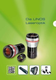
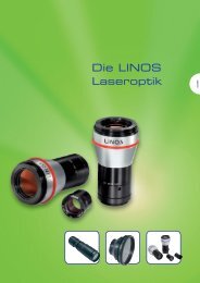
<strong>The</strong> <strong>LINOS</strong><strong>Laseroptics</strong> <strong>and</strong> <strong>Lenses</strong>Benefit from our many years of experiencein the development of optical systems for lasermaterial processing.Our broad selection of beam expansion systems<strong>and</strong> F-<strong>The</strong>ta lenses meets even themost stringent dem<strong>and</strong>s. This comprehensive<strong>LINOS</strong> range covers everything from fixedbeam exp<strong>and</strong>ers to modular, variable <strong>and</strong>motorized beam exp<strong>and</strong>ers. We also manufacturelaser beam homogenizers in cooperationwith one of the market leaders in thisfield. <strong>The</strong> high numerical aperture of <strong>LINOS</strong>laser lenses has gained them wide popularity.<strong>LINOS</strong> quality criteria:• Sophisticated design• Many years of experience• Latest optical, mechanical <strong>and</strong> mounttechnology!Special features:Flexible <strong>and</strong> economical: the modularbm.x expansion system.Ideal areas of application:Beam focusing, beam expansion,beam homogenizing <strong>and</strong> more,for laser material processing.412US-Phone +1 585 223-2370 UK-Phone +44 2380 744 500
<strong>Laseroptics</strong> <strong>and</strong> <strong>Lenses</strong>F-<strong>The</strong>ta-Ronar <strong>Lenses</strong> ________________________F-<strong>The</strong>ta-Ronar <strong>Lenses</strong> 355 nm 414F-<strong>The</strong>ta-Ronar <strong>Lenses</strong> 532 nm 416F-<strong>The</strong>ta-Ronar <strong>Lenses</strong> 830 nm 418F-<strong>The</strong>ta-Ronar <strong>Lenses</strong> 1030/1064 nm 420Protective Glasses 422Focus-Ronar <strong>Lenses</strong> __________________________Focus-Ronar <strong>Lenses</strong> 1064 nm 423Beam Exp<strong>and</strong>ers _ ___________________________Variable Magnification Beam Exp<strong>and</strong>ers 424Motorized Beam Exp<strong>and</strong>ers 425UV Laser Beam Exp<strong>and</strong>er Systems bm.x 426VIS-YAG Laser Beam Exp<strong>and</strong>er Systems bm.x 428NIR Laser Beam Exp<strong>and</strong>er Systems bm.x 430Adapter C-Mount/M30x1 431Fixed Magnification Beam Exp<strong>and</strong>ers forMaterialProcessing (2, 5, 10x) 432Laser Beam Exp<strong>and</strong>er System 4x <strong>and</strong> 7x 433Laser Beam Exp<strong>and</strong>er System 10x 433Laser Beam Exp<strong>and</strong>er System 15x 434Laser Beam Exp<strong>and</strong>er System 16x/25x,without/withspatial filter 434Laser Beam Exp<strong>and</strong>er System 50x <strong>and</strong> 75xwith spatialfilter 435Adapter 1” to W0.8” or Ø 25 mm 436Adapter W0.8”/1” 436Laser Line Projector 436Laser Beam Homogenizer ____________________Laser Beam Homogenizer, Introduction 437Laser Beam Homogenizer for Microbench 438Laser Beam Homogenizer, System 40 / 65 mm 438Germany-Phone: +49 (0) 551/ 6935-0 France-Phone: +33 - 47 25 20 420413
Singlets AchromatsF-<strong>The</strong>ta-Ronar <strong>Lenses</strong> 355 nm<strong>The</strong> following is valid for the overviewtables at the bottom:••<strong>The</strong> entrance beam diameter (beam-Ø)refers to the intensity 1/e 2 at Gaussianillumination. <strong>The</strong> image spot diameter(spot-Ø) refers to the intensity 1/e 2 atGaussian illumination. It can becalculated by the formula:Spot-Ø = 1.83 x λ x EFL / beam-ØSpot-Ø: image spot diameter [μm]1.83: factor of apodisationλ: wavelength [nm]EFL: focal length [mm]Beam-Ø: entrance beam diameter [mm]••<strong>The</strong> mirror distances m1 <strong>and</strong> m2 arerecommended values••<strong>The</strong> overall scan angle Ñ refers to themaximum diagonal scan angle••<strong>The</strong> scan length can be calculated withthe formula:••<strong>The</strong> listed F-<strong>The</strong>ta-Ronar lensesaccomplish the F-<strong>The</strong>ta-conditionbetterthan 0.1% except for a fewversions.<strong>The</strong>se lenses which have alarger scanfield due to distortion areindicated with**.••<strong>The</strong> effective focal length (EFL), flangefocal length (FFL) <strong>and</strong> back focallength(BFL) have been calculated bymeans ofparaxial relations (for raysclose to theoptical axis). In reality,they can slightlydeviate from the datashown in thefollowing tables by theactual entrancebeam diameters <strong>and</strong>mirror positionsused.• • <strong>The</strong> data for the entrance beamdiameter <strong>and</strong> the mirror positions arerecommended values. Changing theirvalues will affect both the image spotdiameter <strong>and</strong> the maximum possiblescanangle/diagonal.2y‘= EFL x 2Ð x π/1802y‘: scan length or diagonal [mm]EFL: focal length [mm]2Ð: overall scan angle [°]π/180: conversion factor into radiansF-<strong>The</strong>ta-Ronar 355 nmProtectiveglassNominal focallength [mm]Effective focallength [mm] EFLBack focal length (fromvertexof last element orfromprotective glasssurface) [mm]BFLFlange focal length(distancefrommechanical flange tofocus plane) [mm] FFLScanlengthordiagonal forareascans[mm]2y'PG3 160 160.1 183.8 189.2 139.7PG4* 161 161 202.9 208.3 140.5PG11* 255** 254.7 321 365.7 240.4* With fused silica lenses** Meets F-<strong>The</strong>ta condition better than 1%414US-Phone +1 585 223-2370 UK-Phone +44 2380 744 500
Singlets AchromatsF-<strong>The</strong>ta-Ronar <strong>Lenses</strong> 532 nm<strong>The</strong> following is valid for the overviewtables at the bottom:••<strong>The</strong> entrance beam diameter (beam-Ø)refers to the intensity 1/e 2 at Gaussianillumination. <strong>The</strong> image spot diameter(spot-Ø) refers to the intensity 1/e 2 atGaussian illumination. It can becalculated by the formula:Spot-Ø = 1.83 x λ x EFL / beam-ØSpot-Ø: image spot diameter [μm]1.83: factor of apodisationλ: wavelength [nm]EFL: focal length [mm]Beam-Ø: entrance beam diameter [mm]••<strong>The</strong> mirror distances m1 <strong>and</strong> m2 arerecommended values••<strong>The</strong> overall scan angle Ñ refers to themaximum diagonal scan angle••<strong>The</strong> scan length can be calculated withthe formula:••<strong>The</strong> listed F-<strong>The</strong>ta-Ronar lensesaccomplish the F-<strong>The</strong>ta-conditionbetterthan 0.1% except for a fewversions.<strong>The</strong>se lenses which have alarger scanfield due to distortion areindicated with**.••<strong>The</strong> effective focal length (EFL), flangefocal length (FFL) <strong>and</strong> back focallength(BFL) have been calculated bymeans ofparaxial relations (for raysclose to theoptical axis). In reality,they can slightlydeviate from the datashown in thefollowing tables by theactual entrancebeam diameters <strong>and</strong>mirror positionsused.• • <strong>The</strong> data for the entrance beamdiameter <strong>and</strong> the mirror positions arerecommended values. Changing theirvalues will affect both the image spotdiameter <strong>and</strong> the maximum possiblescanangle/diagonal.2y‘= EFL x 2Ð x π/1802y‘: scan length or diagonal [mm]EFL: focal length [mm]2Ð: overall scan angle [°]π/180: conversion factor into radiansF-<strong>The</strong>ta-Ronar 532 nmProtectiveglassNominal focallength [mm]Effectivefocal length[mm] EFLBack focal length(from vertexof lastelement or fromprotective glasssurface) [mm]BFLFlange focallength (distancefrom mechanicalflange tofocusplane) [mm] FFLScanlengthordiagonal forareascans[mm]2y'Maximumscan field[mm 2 ]PG1 63 62.3 78 87.7 40.3 28.5 x 28.5PG1 100 99.5 122.2 131.8 61.5 43.5 x 43.5PG8 100 94 96.1 98.7 82 58 x 58100 94 111.4 98.2 82 58 x 58PG7 100* Telecentric Lens 100.2 129.5 195.8 77 54.4 x 54.4PG8 160 159.6 181.6 184.2 139.2 98.4 x 98.4160 159.6 188.6 183.7 139.2 98.4 x 98.4PG12 160** Power-Series 160 188.3 203.5 139.6 98.7 x 98.7PG1 160*** 160.5 187.7 195.3 99.2 70.1 x 70.1PG7 250 250.2 291.4 337.1 218.4 154.4 x 154.4PG1 254 254 289.4 303.5 156.9 111 x 111PG7 330 329.9 386.2 438.3 287.9 203.6 x 203.6330 329.9 389.5 437.2 287.9 203.6 x 203.6PG7 330 Power-Series 329.9 391.9 444 287.9 203.6 x 203.6PG7 420 419.9 493.3 545 410.4 290.2 x 290.2420 419.9 497.1 543.9 410.4 290.2 x 290.2PG7 420 Power-Series 419.8 497.5 549.2 410.4 290.2 x 290.2635 634.6 772.6 833.8 564.9 399.4 x 399.4* Meets F-<strong>The</strong>ta condition better than 3.4%** Meets F-<strong>The</strong>ta condition better than 0.5%*** Meets F-<strong>The</strong>ta condition better than 1%416US-Phone +1 585 223-2370 UK-Phone +44 2380 744 500
<strong>Laseroptics</strong> <strong>and</strong> <strong>Lenses</strong><strong>Laseroptics</strong>Overall scanangle [°] ±ÑEntrancebeambundlediameter[mm] ØbeamImage pointdiameter(1/e 2 ) forGaussianillumination [μm]Mirror distances[mm] m1/m2Screw thread orlens diameterOrder-No±18.5 4.5 13 10.0/15.0 M39x1 4401-387-000-21±17.7 8 12 10.0/13.5 M39x1 4401-425-000-21±25.0 6 15 16.0/12.0 M85x1 4401-304-000-21±25.0 6 15 16.0/12.0 M85x1 4401-304-000-20±22.0 15 7 20.0/32.2 M85x1 4401-461-000-21±25.0 10 16 16.0/12.0 M85x1 4401-305-000-21±25.0 10 16 16.0/12.0 M85x1 4401-305-000-20±25.0 15 12 16.0/16.0 M85x1 4401-482-000-21±17.7 7 22 10.0/13.5 M39x1 4401-386-000-21±25.0 20 12 22.0/24.0 M85x1 4401-289-000-20±17.7 8 31 10.0/19.2 M39x1 4401-454-000-21±25.0 14 23 18.0/24.0 M85x1 4401-361-000-21±25.0 14 23 18.0/24.0 M85x1 4401-361-000-20±25.0 14 23 18.0/24.0 M85x1 4401-485-000-21±28.0 15 27 30.0/16.0 M85x1 4401-357-000-21±28.0 15 27 30.0/16.0 M85x1 4401-357-000-20±28.0 15 27 30.0/16.0 M85x1 4401-489-000-21±25.5 20 31 30.0/20.0 D106 4401-332-000-20Germany-Phone: +49 (0) 551/ 6935-0 France-Phone: +33 - 47 25 20 420417
Singlets AchromatsF-<strong>The</strong>ta-Ronar <strong>Lenses</strong> 830 nm<strong>The</strong> following is valid for the overviewtables at the bottom:••<strong>The</strong> entrance beam diameter (beam-Ø)refers to the intensity 1/e 2 at Gaussianillumination. <strong>The</strong> image spot diameter(spot-Ø) refers to the intensity 1/e 2 atGaussian illumination. It can becalculated by the formula:Spot-Ø = 1.83 x λ x EFL / beam-ØSpot-Ø: image spot diameter [μm]1.83: factor of apodisationλ: wavelength [nm]EFL: focal length [mm]Beam-Ø: entrance beam diameter [mm]••<strong>The</strong> mirror distances m1 <strong>and</strong> m2 arerecommended values••<strong>The</strong> overall scan angle Ñ refers to themaximum diagonal scan angle••<strong>The</strong> scan length can be calculated withthe formula:••<strong>The</strong> listed F-<strong>The</strong>ta-Ronar lensesaccomplish the F-<strong>The</strong>ta-conditionbetterthan 0.1% except for a fewversions.<strong>The</strong>se lenses which have alarger scanfield due to distortion areindicated with**.••<strong>The</strong> effective focal length (EFL), flangefocal length (FFL) <strong>and</strong> back focallength(BFL) have been calculated bymeans ofparaxial relations (for raysclose to theoptical axis). In reality,they can slightlydeviate from the datashown in thefollowing tables by theactual entrancebeam diameters <strong>and</strong>mirror positionsused.• • <strong>The</strong> data for the entrance beamdiameter <strong>and</strong> the mirror positions arerecommended values. Changing theirvalues will affect both the image spotdiameter <strong>and</strong> the maximum possiblescanangle/diagonal.2y‘= EFL x 2Ð x π/1802y‘: scan length or diagonal [mm]EFL: focal length [mm]2Ð: overall scan angle [°]π/180: conversion factor into radiansF-<strong>The</strong>ta-Ronar 830 nmNominal focallength [mm]Effective focallength [mm] EFLBack focal length (fromvertexof last element orfromprotective glasssurface) [mm]BFLFlange focal length(distancefrommechanical flange tofocus plane) [mm] FFLScanlengthordiagonal forareascans[mm]2y'Maximumscan field[mm 2 ]63 63.3 80.6 88 40.9 28.9 x 28.9330 325.8 386 434.8 301.4 213.1 x 213.1420 413.7 491.2 539.7 404.3 285.9 x 285.9418US-Phone +1 585 223-2370 UK-Phone +44 2380 744 500
<strong>Laseroptics</strong> <strong>and</strong> <strong>Lenses</strong><strong>Laseroptics</strong>Overall scanangle [°]±ÑEntrancebeambundlediameter[mm] ØbeamImage pointdiameter(1/e 2 ) forGaussianillumination [μm]Mirror distance[mm] (m1/m2)Screw thread orlens diameterOrder-No±18.5 5.6 17 10/15 M39x1 4401-388-000-20±26.5 16 31 18/24 M85x1 4401-360-000-22±28.0 15 42 30/16 M85x1 4401-350-000-22Germany-Phone: +49 (0) 551/ 6935-0 France-Phone: +33 - 47 25 20 420419
Singlets AchromatsF-<strong>The</strong>ta-Ronar <strong>Lenses</strong> 1030/1064 nm<strong>The</strong> following is valid for the overviewtables at the bottom:••<strong>The</strong> entrance beam diameter (beam-Ø)refers to the intensity 1/e 2 at Gaussianillumination. <strong>The</strong> image spot diameter(spot-Ø) refers to the intensity 1/e 2 atGaussian illumination. It can becalculated by the formula:Spot-Ø = 1.83 x λ x EFL / beam-ØSpot-Ø: image spot diameter [μm]1.83: factor of apodisationλ: wavelength [nm]EFL: focal length [mm]Beam-Ø: entrance beam diameter [mm]••<strong>The</strong> mirror distances m1 <strong>and</strong> m2 arerecommended values••<strong>The</strong> overall scan angle Ñ refers to themaximum diagonal scan angle••<strong>The</strong> scan length can be calculated withthe formula:••<strong>The</strong> listed F-<strong>The</strong>ta-Ronar lensesaccomplish the F-<strong>The</strong>ta-conditionbetterthan 0.1% except for a fewversions.<strong>The</strong>se lenses which have alarger scanfield due to distortion areindicated with**.••<strong>The</strong> effective focal length (EFL), flangefocal length (FFL) <strong>and</strong> back focallength(BFL) have been calculated bymeans ofparaxial relations (for raysclose to theoptical axis). In reality,they can slightlydeviate from the datashown in thefollowing tables by theactual entrancebeam diameters <strong>and</strong>mirror positionsused.• • <strong>The</strong> data for the entrance beamdiameter <strong>and</strong> the mirror positions arerecommended values. Changing theirvalues will affect both the image spotdiameter <strong>and</strong> the maximum possiblescanangle/diagonal.2y‘= EFL x 2Ð x π/1802y‘: scan length or diagonal [mm]EFL: focal length [mm]2Ð: overall scan angle [°]π/180: conversion factor into radiansF-<strong>The</strong>ta-Ronar 1030/1064 nmProtectiveglassNominal focallength [mm]Effective focallength [mm] EFLBack focal length (fromvertexof last elementor fromprotective glasssurface) [mm]BFLFlange focal length(distancefrommechanical flange tofocus plane) [mm] FFLPG1 63 63.9 79.4 89.1 41.2PG1 100 99.9 120.6 130.3 61.7PG2 100 99.7 103.4 106 87100 99.7 118.4 105.5 87PG9 100 * Telecentric 100.1 128.9 195.2 76.9PG2 160 160.3 181.8 184.4 139.9160 160.3 189.1 183.8 139.9PG1 160 ** 159.9 186.5 194.1 98.8PG5 163 163.1 190 219.1 162.3163 163.1 192.7 218.1 162.3PG6 254 254.4 299.1 344.8 222PG10 254 for 1030 nm 254.4 299.1 344.8 222PG1 254 254.1 289.3 303.4 157PG6 330 331.4 390.5 442.6 306.6330 331.4 392.8 441.6 306.6PG6 420 420.5 497.1 548.8 411420 420.5 499.2 547.7 411Scanlengthordiagonal forareascans[mm]2y'* Meets F-<strong>The</strong>ta condition better than 3.4%** Meets F-<strong>The</strong>ta condition better than 1%420US-Phone +1 585 223-2370 UK-Phone +44 2380 744 500
<strong>Laseroptics</strong> <strong>and</strong> <strong>Lenses</strong><strong>Laseroptics</strong>Maximumscan field[mm 2 ]Overall scanangle [°] ±ÑEntrancebeambundlediameter[mm] ØbeamImage pointdiameter(1/e 2 ) forGaussianillumination [μm]Mirror distances[mm] m1/m2Screw threador lensdiameterOrder-No29.1 x 29.1 ±18.5 6.2 20 10.0/15.0 M39x1 4401-387-000-2143.6 x 43.6 ±17.7 8 24 10.0/13.5 M39x1 4401-426-000-2161.5 x 61.5 ±25.0 12 16 16.0/12.0 M85x1 4401-302-000-2161.5 x 61.5 ±25.0 12 16 16.0/12.0 M85x1 4401-302-000-2054.4 x 54.4 ±22.0 15 13 20.0/32.0 M85x1 4401-464-000-2198.9 x 98.9 ±25.0 12 26 16.0/12.0 M85x1 4401-301-000-2198.9 x 98.9 ±25.0 12 26 16.0/12.0 M85x1 4401-301-000-2069.9 x 69.9 ±17.7 8 39 10.0/13.5 M39x1 4401-378-000-21114.8 x 114.8 ±28.5 10 32 13.0/24.0 M76x1 4401-261-000-21114.8 x 114.8 ±28.5 10 32 13.0/24.0 M76x1 4401-261-000-20157 x 157 ±25.0 20 25 30.0/16.0 M85x1 4401-288-000-20157 x 157 ±25.0 20 25 30.0/16.0 M85x1 4401-288-000-23111 x 111 ±17.7 8 62 10.0/19.2 M39x1 4401-453-000-21216.8 x 216.8 ±26.5 16 40 18.0/24.0 M85x1 4401-360-000-21216.8 x 216.8 ±26.5 16 40 18.0/24.0 M85x1 4401-360-000-20290.6 x 290.6 ±28.0 15 55 30.0/16.0 M85x1 4401-350-000-21290.6 x 290.6 ±28.0 15 55 30.0/16.0 M85x1 4401-350-000-20Germany-Phone: +49 (0) 551/ 6935-0 France-Phone: +33 - 47 25 20 420421
Singlets AchromatsProtective GlassesProtective GlassesProtective glass Protective glass diameter [mm] Protective glass thickness [mm] AR coated for λ [nm] Order-NoPG 1 42 1.6 532/1064 4401-378-003-00PG 2 75 1.6 1064+VIS 4401-301-001-00PG 3 75 1.5 355 4401-398-004-00PG 4* 75 1.5 355 4401-399-005-01PG 5 100 3 1064+VIS 4401-261-004-00PG 6 113 3 1064+VIS 4401-288-005-01PG 7 113 3 532 4401-289-007-00PG 8 75 1.6 532 4401-304-005-00PG 9 113 3 532/1064 4401-288-015-00PG 10 113 3 1030 4401-288-020-00PG11* 113 3 355 4401-481-005-00PG12 85 1.6 532 4401-482-004-01* quartz422US-Phone +1 585 223-2370 UK-Phone +44 2380 744 500
<strong>Laseroptics</strong> <strong>and</strong> <strong>Lenses</strong>Focus-Ronar <strong>Lenses</strong> 1064 nm• Focussing lenses are optimized forhigh precision applications, used inlaser systems for welding, cutting,drilling <strong>and</strong> structuring.• This lens series is available in a numberof common focal lengths, rangingfrom 56 mm to 120 mm.• <strong>The</strong>y allow a maximum possibleentrance beam diameter of upto 35mm.• <strong>The</strong> broadb<strong>and</strong> coating is optimizedfor 1064 nm with good inspectionperformance at VIS wavelengths.• Additionally the Focus-Ronar lensescan also be used at 532 nm.• With the design of three high quality<strong>and</strong> optimized lens elements adiffraction-limited focus is achieved.• It is possible to get one st<strong>and</strong>ardizedmechanical design for various focallengths.• Thanks to an outst<strong>and</strong>ing mechanical<strong>and</strong> optical precision the lenses can beexchanged quickly <strong>and</strong> flexiblywithoutany adjustment.<strong>Laseroptics</strong>Focus-Ronar <strong>Lenses</strong> for 1064 nmEffective focallength [mm] EFLClearaperture Ø[mm] CADiameter[mm] DLength[mm] LFlange focallength [mm] FFLImage point diameter*[µm] (@input beam25 mm)ØspotOrder-No56 34.0 41 h7 24.6 46.7 4.5 4401-487-000-2077 35.4 41 h7 18.9 72.2 6 4401-486-000-2090 35.4 41 h7 33.6 73.7 7 4401-490-000-20120 35.0 41 h7 24.0 110.7 9.5 4401-420-000-20Technical data for Focus-Ronar lenses with awavelength of 532 nm are available on request.* <strong>The</strong> entrance beam diameter (Øbeam) <strong>and</strong> the imagepoint diameter (Øspot) refer to intensity 1/e 2 atGaussian illumination. It can be calculated by theformula:Øspot = 1.83 x λ x EFL / ØbeamØspot: image spot diameter [μm]1.83: factor of apodisationλ: wavelength [nm]EFL: focal length [mm]Øbeam: entrance beam diameter [mm]Germany-Phone: +49 (0) 551/ 6935-0 France-Phone: +33 - 47 25 20 420423
Singlets AchromatsVariable Magnification Beam Exp<strong>and</strong>ers• Continuous variation of magnification2x ... 8x possible• Wavelengths 355 nm, 405 nm, 532 nm,633/780/830 nm or 1064 nm• Settings of zoom <strong>and</strong> focussing scalesaccording to product specific graph• Mounting in customer machine atsurface [A]• Consideration of convergencecorrection at maximum setting ofmovable lens elements2-8x Beam Exp<strong>and</strong>erVariable Magnification Beam Exp<strong>and</strong>ersWavelength[nm]Magnifica tionfactorMax. entrancebeam-Ø at 1/e 2 Gaussian beam[mm]Max. exitbeam-Ø[mm]LenselementsEntrance lensmade ofquartzMountingdiameterorthread [mm]Order-No355 2 ... 8xvariable 3.4* 31 4 x 37.6 -0.01 4401-402-000-20405 2 ... 8xvariable 6.0* 31 4 37.6 -0.01 4401-380-000-20532 2 ... 8xvariable 4.0* 31 4 x 37.6 -0.01 4401-446-000-20532 2 ... 8xvariable 8.0* 31 4 37.6 -0.01 4401-257-000-20633/780/830 2 ... 8xvariable 8.0* 31 4 37.6 -0.01 4401-258-000-201064 2 ... 8xvariable 4.0* 31 4 x 37.6 -0.01 4401-359-000-201064 2 ... 8xvariable 8.0* 31 4 37.6 -0.01 4401-256-000-20* Beyond defined zoom factors, the entrance beam-Ø max. = 31mm / zoom factor.Details can be found in the respective data sheet.424US-Phone +1 585 223-2370 UK-Phone +44 2380 744 500
<strong>Laseroptics</strong> <strong>and</strong> <strong>Lenses</strong>Motorized Beam Exp<strong>and</strong>ers• Continuous variable magnification2x...8x• Wavelength 1064 nm or 532 nm(onrequest)• User friendly WindowsTM basedsoftware 8 position pre-sets <strong>and</strong>detailed manual• Reduced machine setup times byautomatic change of magnification• Laser protection class is maintained,asopening of the machine is omitted<strong>Laseroptics</strong>Motorized Beamexp<strong>and</strong>er with ControllerMotorised Beam Exp<strong>and</strong>ersWavelength[nm]Magnifica tionfactorMax. entrancebeamØ at 1/e 2 Gaussian beam[mm]Max. exitbeam-Ø[mm]LenselementsEntrancelensmadeofquartzMountingdiameterorthread [mm]Order-No532 2 ... 8xvariabelmoto rised 8.0* 31 4 39.0 h11 4401-351-000-211064 2 ... 8xvariabelmoto rised 8.0* 31 4 39.0 h11 4401-345-000-21* beyond defined zoom factors, the entrance beam-Ø max. = 31mm / zoom factorDetails can be found in the respective data sheet.ControllerAC SupplyVoltage [V]AC SupplyFrequency[Hz]ACPowerSupply[A]Outerdimensions[mm 3 ]SoftwarePlatformPCInterfaceSub-DCabel (9Pins,1:1)[mm]Supplyline[mm]Order-No100- 240 (±10%) 47 - 63 0.2 max 110 x 61 x 35 Windows95/98/NT 4.0/2000/XP RS232C ca. 2000 ca. 2000 4402-004-000-21Germany-Phone: +49 (0) 551/ 6935-0 France-Phone: +33 - 47 25 20 420425
Singlets AchromatsUV Laser Beam Exp<strong>and</strong>er Systems bm.x<strong>The</strong> laser beam exp<strong>and</strong>er system bm.x isthe only modular beam exp<strong>and</strong>er systemavailable worldwide. Its sophisticateddesign allows you to change theexpansion ratio by exchanging a module- without any re-calibration.Of course, the beam exp<strong>and</strong>er familybm.x offers the <strong>LINOS</strong> precision.• Worldwide unique modular design• High performance optical <strong>and</strong> coatingdesign• For laser beam exp<strong>and</strong>ing (exitaperture 30 mm)• Entrance lens fabricated from fusedsilica to reduce laser beam divergence• Quick change between differentexpansion ratios by modular structurewith bm.x basic module <strong>and</strong>exchangeablebm.x inserts• ARB2 UV coating for 266 - 405 nm• Residual reflectance: < 0.5 %• Damage threshold > 2 J/cm 2 for 10 nslaser pulses at 308 nm• Internal focusing• Other expansion ratios in preparation.bm.x UV fully configured systemsItem Title Expansionratio Maximum beam entrancediameter(mm)Wavelength(nm)CoatingOrder-NoBeam exp<strong>and</strong>er bm.x UV1.5x 1.5x 6 266-405 ARB2 UV G03 8690 522Beam exp<strong>and</strong>er bm.x UV 2x 2x 6 266-405 ARB2 UV G03 8691 522Beam exp<strong>and</strong>er bm.x UV2.5x 2.5x 6 266-405 ARB2 UV G03 8692 522Components bm.x Laser Beam Exp<strong>and</strong>er UVItem Title Expansion ratio Wavelength (nm) Coating Order-Nobm.x UV insert 1.5x 1.5x 266-405 ARB 2 UV G03 8690 931bm.x UV insert 2x 2x 266-405 ARB 2 UV G03 8691 931bm.x UV insert 2.5x 2.5x 266-405 ARB 2 UV G03 8692 931bm.x UV basic module 1.5x - 2.5x 266-405 ARB 2 UV G03 8690 935426US-Phone +1 585 223-2370 UK-Phone +44 2380 744 500
<strong>Laseroptics</strong> <strong>and</strong> <strong>Lenses</strong><strong>Laseroptics</strong>Mounting options:- Direct mounting with M43x0.5- Mounting with flange D80 (M4 or M6 screws)- Mounting with clamp holderAdditional mounting components:- Flange D80, G03 8669 000- Clamp holder 35, G06 1244 000- Tube wrench 22/1.5, G06 1105 000A closer look<strong>The</strong> bm.x Series laser beam exp<strong>and</strong>er systems are the world's only modularlaser beam exp<strong>and</strong>er systems. Simply replacing one insert withanother alters the expansion ratio, with no additional calibration required.Germany-Phone: +49 (0) 551/ 6935-0 France-Phone: +33 - 47 25 20 420427
Singlets AchromatsVIS-YAG Laser Beam Exp<strong>and</strong>er Systems bm.x<strong>The</strong> laser beam exp<strong>and</strong>er system bm.x isthe only modular beam exp<strong>and</strong>er systemavailable worldwide. <strong>The</strong> sophisticateddesign allows you to change theexpansion ratio by exchanging a modulewithout any re-calibration.Of course, the beam exp<strong>and</strong>er bm.xfamily offers the <strong>LINOS</strong> precision.Due to the ARBS coating the bm.x can beused with Nd:YAG Laser as well as HeNeLasers in the visible wavelength range.• Quick change between differentexpansion ratios by modular structurewith bm.x basic module <strong>and</strong>exchangeablebm.x inserts• ARBS coating for high power Nd:YAG-Laser (532 nm, 1064 nm)• Internal focusingARBS:• Residual reflectance: < 1 % (450 - 650nm) / < 0.5 % (480 - 640 nm) / < 0.3 %(1061 - 1064 nm)• Damage threshold: > 10 J/cm 2 for10ns laser pulses at 1064 nm• Worldwide unique modular design• High performance optical <strong>and</strong> coatingdesign• For laser beam exp<strong>and</strong>ing (exitaperture 30 mm)• Entrance lens fabricated from fusedsilica to reduce laser beam divergenceComponents bm.x VIS-YAG 1,5x, 2x <strong>and</strong> 2,5xDescription E.r.* Wavelength (nm) Coating Order-Nobm.x VIS-YAG insert 1,5x 1,5x 450-650/1064 ARBS G03 8690 911bm.x VIS-YAG insert 2x 2x 450-650/1064 ARBS G03 8691 911bm.x VIS-YAG insert 2,5x 2,5x 450-650/1064 ARBS G03 8692 911bm.x VIS-YAG basic module for 1,5x, 2x <strong>and</strong> 2,5x 450-650/1064 ARBS G03 8690 905*E.r. = expansion ratiobm.x VIS-YAG fully configured systemsDescription E.r.* Wavelength (nm) Coating Order-NoBeam exp<strong>and</strong>er bm.x VIS-YAG 1,5x 1,5x 450-650/1064 ARBS G03 8690 000Beam exp<strong>and</strong>er bm.x VIS-YAG 2x 2x 450-650/1064 ARBS G03 8691 000Beam exp<strong>and</strong>er bm.x VIS-YAG 2,5x 2,5x 450-650/1064 ARBS G03 8692 000Beam exp<strong>and</strong>er bm.x VIS-YAG 3x 3x 450-650/1064 ARBS G03 8673 000Beam exp<strong>and</strong>er bm.x VIS-YAG 4x 4x 450-650/1064 ARBS G03 8674 000Beam exp<strong>and</strong>er bm.x VIS-YAG 5x 5x 450-650/1064 ARBS G03 8675 000Beam exp<strong>and</strong>er bm.x VIS-YAG 8x 8x 450-650/1064 ARBS G03 8678 000Beam exp<strong>and</strong>er bm.x VIS-YAG 10x 10x 450-650/1064 ARBS G03 8670 000*E.r. = expansion ratioComponents bm.x VIS-YAG 3x, 4x, 5x, 8x <strong>and</strong> 10xDescription E.r.* Wavelength (nm) Coating Order-Nobm.x VIS-YAG insert 3x 3x 450-650/1064 ARBS G03 8673 911bm.x VIS-YAG insert 4x 4x 450-650/1064 ARBS G03 8674 911bm.x VIS-YAG insert 5x 5x 450-650/1064 ARBS G03 8675 911bm.x VIS-YAG insert 8x 8x 450-650/1064 ARBS G03 8678 911bm.x VIS-YAG insert 10x 10x 450-650/1064 ARBS G03 8670 911bm.x VIS-YAG basic module for 3x, 4x, 5x, 8x <strong>and</strong> 10x 450-650/1064 ARBS G03 8670 905*E.r. = expansion ratio428US-Phone +1 585 223-2370 UK-Phone +44 2380 744 500
<strong>Laseroptics</strong> <strong>and</strong> <strong>Lenses</strong><strong>Laseroptics</strong>Mounting options:- Direct mounting with M43x0.5- Mounting with flange D80 (M4 or M6 screws)- Mounting with clamp holderAdditional mounting components:- Flange D80, G03 8669 000- Clamp holder 35, G06 1244 000- Tube wrench 22/1.5, G06 1105 000A closer look<strong>The</strong> bm.x Series laser beam exp<strong>and</strong>er systems are the world's only modularlaser beam exp<strong>and</strong>er systems. Simply replacing one insert withanother alters the expansion ratio, with no additional calibration required.Germany-Phone: +49 (0) 551/ 6935-0 France-Phone: +33 - 47 25 20 420429
Singlets AchromatsNIR Laser Beam Exp<strong>and</strong>er Systems bm.x<strong>The</strong> laser beam exp<strong>and</strong>er system bm.x isthe only modular beam exp<strong>and</strong>er systemavailable worldwide. <strong>The</strong> sophisticateddesign allows you to change theexpansion ratio by exchanging a modulewithout any re-calibration.Of course, the beam exp<strong>and</strong>er bm.xfamily offers the <strong>LINOS</strong> precision.• Quick change between differentexpansion ratios by modular structurewith bm.x basic module <strong>and</strong>exchangeablebm.x inserts• ARB2 NIR coating for 750 - 950 nm• Residual reflectance: < 0.5 %• Damage threshold: > 10 J/cm 2 for20ns laser pulses at 1064 nm• Internal focusing• Worldwide unique modular design• High performance optical <strong>and</strong> coatingdesign• For laser beam exp<strong>and</strong>ing (exitaperture 30 mm)• Entrance lens fabricated from fusedsilica to reduce laser beam divergencebm.x Laser Beam Exp<strong>and</strong>er NIR fully configured systemsDescription E.r.* Wavelength (nm) Coating Order-NoBeam exp<strong>and</strong>er bm.x NIR 1,5x 1,5x 750-950 ARB2 NIR G03 8690 525Beam exp<strong>and</strong>er bm.x NIR 2x 2x 750-950 ARB2 NIR G03 8691 525Beam exp<strong>and</strong>er bm.x NIR 2,5x 2,5x 750-950 ARB2 NIR G03 8692 525Beam exp<strong>and</strong>er bm.x NIR 3x 3x 750-950 ARB2 NIR G03 8673 525Beam exp<strong>and</strong>er bm.x NIR 4x 4x 750-950 ARB2 NIR G03 8674 525Beam exp<strong>and</strong>er bm.x NIR 5x 5x 750-950 ARB2 NIR G03 8675 525Beam exp<strong>and</strong>er bm.x NIR 8x 8x 750-950 ARB2 NIR G03 8678 525Beam exp<strong>and</strong>er bm.x NIR 10x 10x 750-950 ARB2 NIR G03 8670 525*E.r. = expansion ratioComponents bm.x Laser Beam Exp<strong>and</strong>er NIR 3x, 4x, 5x, 8x <strong>and</strong> 10xDescription E.r.* Wavelength (nm) Coating Order-Nobm.x NIR insert 3x 3x 750-950 ARB 2 NIR G03 8673 921bm.x NIR insert 4x 4x 750-950 ARB 2 NIR G03 8674 921bm.x NIR insert 5x 5x 750-950 ARB 2 NIR G03 8675 921bm.x NIR insert 8x 8x 750-950 ARB 2 NIR G03 8678 921bm.x NIR insert 10x 10x 750-950 ARB 2 NIR G03 8670 921bm.x NIR basic module for 3x, 4x, 5x, 8x <strong>and</strong> 10x 750-950 ARB 2 NIR G03 8670 925*E.r. = expansion ratioComponents bm.x Laser Beam Exp<strong>and</strong>er NIR 1,5x, 2x <strong>and</strong> 2,5xDescription E.r.* Wavelength (nm) Coating Order-Nobm.x NIR insert 1,5x 1,5x 750-950 ARB 2 NIR G03 8690 921bm.x NIR insert 2x 2x 750-950 ARB 2 NIR G03 8691 921bm.x NIR insert 2,5x 2,5x 750-950 ARB 2 NIR G03 8692 921bm.x NIR basic module for 1,5x, 2x <strong>and</strong> 2,5x 750-950 ARB 2 NIR G03 8690 925*E.r. = expansion ratio430US-Phone +1 585 223-2370 UK-Phone +44 2380 744 500
<strong>Laseroptics</strong> <strong>and</strong> <strong>Lenses</strong><strong>Laseroptics</strong>Mounting options:- Direct mounting with M43x0.5- Mounting with flange D80 (M4 or M6 screws)- Mounting with clamp holderAdditional mounting components:- Flange D80, G03 8669 000- Clamp holder 35, G06 1244 000- Tube wrench 22/1.5, G06 1105 000Adapter C-Mount/M30x1For adaptation of the laser expansionsystems bm.x on components withC-mount connection:• Enables the connection to HeNe-laserswith C-mount threads• Serves as connection of the laserexpansion systems bm.x to the <strong>LINOS</strong>tube construction system CAdapter C-Mount/M30x1Item TitleOrder-NoAdapter C-Mount/M30x1 G03 8699 000Germany-Phone: +49 (0) 551/ 6935-0 France-Phone: +33 - 47 25 20 420431
Singlets AchromatsFixed Magnification Beam Exp<strong>and</strong>ers for MaterialProcessing (2, 5, 10x)• Expansion 2x, 5x or 10x• Wavelength 532 nm or 1064 nm• Entrance lens made of quartz• High imaging quality• Mounting in customer machine atØ27h7 or C-Mount• Pointing stability during adjustmentofdivergence• Easy fine focussing using an engravedscale• with a vernier• Consideration of convergencecorrection when using maximumfocusing spanBeam Exp<strong>and</strong>er 2x for 1064 nmFixed Magnification Beam Exp<strong>and</strong>ersWavelength[nm]Magnifi cationfactorOptimumentrancebeam-Ø at 1/e 2 Gaussian beam[mm]Max.exitbeam-Ø[mm]LenselementsEntrancelensmadeofquartzMounting diameteror thread [mm]Order-No532 2xfixed 2 8 3 x 27.0 h7 1-32UN-2B C-Mount 4401-414-000-20532 5xfixed 2 20 3 x 27.0 h7 1-32UN-2B C-Mount 4401-415-000-20532 10xfixed 1 20 3 x 27.0 h7 1-32UN-2B C-Mount 4401-416-000-201064 2xfixed 2 8 2 x 27.0 h7 1-32UN-2B C-Mount 4401-411-000-201064 5xfixed 2 20 2 x 27.0 h7 1-32UN-2B C-Mount 4401-412-000-201064 10xfixed 1 20 2 x 27.0 h7 1-32UN-2B C-Mount 4401-413-000-20432US-Phone +1 585 223-2370 UK-Phone +44 2380 744 500
<strong>Laseroptics</strong> <strong>and</strong> <strong>Lenses</strong>Laser Beam Exp<strong>and</strong>er System 4x <strong>and</strong> 7x• To generate plane wave fronts• To focus laser beams at long distances• To reduce laser beam divergence• To use in alignment work oroptoelectroniccontrol systems• Equipped with focusable exit optics• Entrance aperture: Ø 4 mm• Exit aperture: Ø 16 mm• Entrance element: plano-concavesinglet• Exit element: focusable from 0.5 m to ∞ (4x); focusable from 1.5 m to ∞ (7x)• Mating thread: 1”x1/32”• Fits directly to most lasers• Broadb<strong>and</strong> anti-reflection coated withARB2 for λ = 450 - 700 nm• Adaptable to Microbench<strong>Laseroptics</strong>Laser Beam Exp<strong>and</strong>er System 4x <strong>and</strong> 7xItem TitleOrder-NoLaser beam exp<strong>and</strong>er system 4x G03 8658 000Laser beam exp<strong>and</strong>er system 7x G03 8659 000Laser Beam Exp<strong>and</strong>er System 10x• To generate plane wave fronts• To focus laser beams at great distances• To reduce laser beam divergence• To use in alignment work oroptoelectroniccontrol systems• Equipped with focusable exit optics• Entrance aperture: Ø 3 mm• Exit aperture: Ø 17 mm• Entrance element: air-spaced achromat• Exit element: focusable from1.5 m to ∞• Mating thread: 1”x1/32”• Fits directly to most lasers• Broadb<strong>and</strong> anti-reflection coated withARB2 for λ = 450 - 700 nm• Adaptable to MicrobenchLaser Beam Exp<strong>and</strong>er System 10xItem TitleOrder-NoLaser beam exp<strong>and</strong>er system 10x G03 8662 000Germany-Phone: +49 (0) 551/ 6935-0 France-Phone: +33 - 47 25 20 420433
Singlets AchromatsLaser Beam Exp<strong>and</strong>er System 15x• To generate plane wave fronts• To focus laser beams at great distances• To reduce laser beam divergence• To use in alignment work oroptoelectroniccontrol systems• Equipped with focusable exit optics• Entrance aperture: Ø 3 mm• Exit aperture: Ø 30 mm• Entrance element: biconvex singlet• Exit element: focusable from 10 m to ∞• Corrected for spherical aberration at633 nm• Mating thread: 1”x1/32”• Fits directly to most lasers• Broadb<strong>and</strong> anti-reflection coated withARB2 for λ = 450 - 700 nm• Adaptable to MicrobenchLaser Beam Exp<strong>and</strong>er System 15xItem TitleOrder-NoLaser beam exp<strong>and</strong>er system 15x G03 8650 000Laser Beam Exp<strong>and</strong>er System 16x/25x, without/withspatial filter• To generate plane wave fronts• To focus laser beams at great distances• To reduce laser beam divergence• To use in alignment work oroptoelectroniccontrol systems• Equipped with focusable exit optics• Entrance aperture: Ø 3 mm• Exit aperture: Ø 30 mm• Entrance element: centerableachromat• Exit element: focusable from 10 m to ∞• Wavefront distortion: < λ/8 at 633 nm• With spatial filters: adjustable in X, Y<strong>and</strong> Z; for 16x: Ø = 30 μm; for 25x:Ø =20 μm• Mating thread: 1”x1/32”• Fits directly to most lasers• Broadb<strong>and</strong> anti-reflection coated withARB2 for λ = 450 - 700 nm• Adaptable to MicrobenchLaser Beam Exp<strong>and</strong>er System 16x <strong>and</strong> 25x, without/with spatial filterItem TitleOrder-NoLaser beam exp<strong>and</strong>er system 16x G03 8652 000Laser beam exp<strong>and</strong>er system 16x with spatial filter G03 8654 000Laser beam exp<strong>and</strong>er system 25x G03 8653 000Laser beam exp<strong>and</strong>er system 25x with spatial filter G03 8655 000434US-Phone +1 585 223-2370 UK-Phone +44 2380 744 500
<strong>Laseroptics</strong> <strong>and</strong> <strong>Lenses</strong>Laser Beam Exp<strong>and</strong>er System 50x <strong>and</strong> 75x with spatialfilter• To generate plane wave fronts• To focus laser beams at great distances• To reduce laser beam divergence• To use in alignment work oroptoelectroniccontrol systems• Equipped with focusable exit optics• Entrance aperture: Ø 3 mm• Exit aperture: Ø 78 mm• Entrance element: centerable bestform lens• Exit element: focusable from 10 m to ∞• Wavefront distortion: < 1λ at 633 nm• Spatial filter: Ø = 10 μm, adjustable inX, Y <strong>and</strong> Z• Mating thread: 1”x1/32”• Fits directly to most lasers• Broadb<strong>and</strong> anti-reflection coated withARB2 for λ = 450 - 700 nm• Adaptable to Microbench<strong>Laseroptics</strong>Laser Beam Exp<strong>and</strong>er System 50x <strong>and</strong> 75x with spatial filterItem TitleOrder-NoLaser beam exp<strong>and</strong>er system 50x with spatial filter G03 8657 000Laser beam exp<strong>and</strong>er system 75x with spatial filter G03 8663 000Germany-Phone: +49 (0) 551/ 6935-0 France-Phone: +33 - 47 25 20 420435
Singlets AchromatsAdapter 1” to W0.8” or Ø 25 mm• Accessory for Laser Beam Exp<strong>and</strong>erSystemsAdapter 1” to W0.8“ or Ø 25 mmItem TitleOrder-NoAdapter 1 G06 1661 000Adapter W0.8”/1”• Accessory for Laser Beam Exp<strong>and</strong>erSystemAdapter W0.8”/1”Item TitleOrder-NoAdapter W0.8 G06 1662 000Laser Line Projector• Accesssory for Laser Beam Exp<strong>and</strong>erSystems• Converts circular laser beams into anarrow line• Mounts onto the entrance aperturesoflaser• Entrance aperture: Ø 4 mm• Focal length: 5 mm• Mating thread: 1”x1/32”• For beam exp<strong>and</strong>er systems withoutspatial filters• Broadb<strong>and</strong> AR-coated forλ = 450 - 700nmLaser Line ProjectorItem TitleOrder-NoLaser line projector G03 8660 000Approx. line dimensions with 4x laserbeam exp<strong>and</strong>er:• at 0.5 m distance: 25 mm x 0.3 mm• at 1 m distance: 60 mm x 0.5 mm• at 10 m distance: 600 mm x 5 mm• (each for a beam entrance Ø = 1 mm)436US-Phone +1 585 223-2370 UK-Phone +44 2380 744 500
<strong>Laseroptics</strong> <strong>and</strong> <strong>Lenses</strong>Laser Beam Homogenizer, IntroductionMany applications, e.g. microscopy <strong>and</strong>material processing, require a very evendistribution of the illuminating light.Non-imaging HomogenizersImaging HomogenizersFor this purpose, microlens basedhomogenizers are available nowadaysfor numerous light sources, ranging fromexcimer lasers to high power LEDs.Two general types are distinguished,Non-Imaging <strong>and</strong> Imaging Homogenizers.Both types split the incident beaminto small sub beams. This is achieved bypassage either through arrays ofcylindrical lenses in a crossed configuration,or through arrays of microlenses. <strong>The</strong>sub beams are then superimposed by aspherical lens in its focal plane, leadingto a homogeneously illuminated field.This spherical lens is called Fourier lens,as it effectively performs a two dimensionalFourier transformation.Fig. 1 Fig. 2Non-Imaging Homogenizers are builtfrom one microlens array <strong>and</strong> onespherical lens (see fig. 1). <strong>The</strong> plane ofhomogenization lies in the focal plane ofthe Fourier lens (FL), the size of thehomogeneously illuminated area isdetermined by:Imaging Homogenizers are built fromtwo microlens arrays <strong>and</strong> one sphericallens (see fig. 2). <strong>The</strong> plane of homogenizationlies in the focal plane of theFourier lens (FL), the size of the homogenizedarea is defined by:with<strong>Laseroptics</strong><strong>The</strong> application itself should be consideredwhen choosing between Non-Imaging <strong>and</strong> Imaging Homogenizer. Asan orientation aid one should considerthe Fresnel number, which is defined formicrolens homogenizers by:where P LArepresents the pitch of themicrolens array, D FTthe size of the flattop in the plane of homogenization, f FLthe focal length of the Fourier lens, <strong>and</strong> lis the wavelength. <strong>The</strong> Fresnel number isthe most important determinant for laserbeam homogenizers based on microlensarrays. As a general rule, the uniformityof the flat top increases with higherFresnel numbersNon-Imaging Homogenizers often showdominant diffraction effects due toFresnel diffraction at the microlens array.In practice, Fresnel numbers of FN >10, orbetter FN >100, lead to homogeneousintensities. Due to the connection of theFresnel number with the size of the flattop, Non-Imaging Homogenizers are thefirst choice for illuminating large areas.For small Fresnel numbers of FN < 10, orwhen a very even distribution is required,Imaging Homogenizers should bechosen.Here, a 12denotes the distance betweenthe two microlens arrays. As withNon-Imaging Homogenizers, the incidentbeam is split into many small sub beamswith the first microlens array. <strong>The</strong> secondmicrolens array then acts, in combinationwith the spherical lens, like an array ofobjective lenses, overlapping the subbeams of the first array in the plane ofhomogenization. As the size of the flattop depends in this case on the distancebetween the two arrays, it can easily beadjusted by moving the second array.However, great care has to be taken thatthe second array is not moved into thefocus plane of the first array, where itcould be damaged by focussed highenergy laser light.Imaging Homogenizers usually use microlensarrays of identical pitch. <strong>The</strong> shapeof the flat top is determined by theshape of the microlenses (e.g. square,round, hexagonal).Germany-Phone: +49 (0) 551/ 6935-0 France-Phone: +33 - 47 25 20 420437
Singlets AchromatsLaser Beam Homogenizer for Microbench• For homogenous intensity distributionsfor laser <strong>and</strong> illumination systems• Production according to customspecifications• Pre-assembled <strong>and</strong> tested• Module consisting of microbenchcomponents• Design of a fly´s eye condenser• Quartz glass for applications from UVto IR• AR coating on request.Device (only mechanical parts) consists of:Item titleOrder-NoMounting plate 25 G06 1010 000Centering mounting plate 25 G06 1025 000Mount CL 22.5 G06 3651 000Aperture 10x10mm* G06 5220 018Aperture 5x5mm* G06 5220 017*Note: You need 2 pieces of the G061-010-000 <strong>and</strong> either 2 pieces of mount G065-220-018 or 2 pieces of mountG065-220-017Microlens arrays <strong>and</strong> Fourier lens depending on custom specifications,screws <strong>and</strong> rods see MicrobenchLaser Beam Homogenizer, System 40 / 65 mm• For homogenous intensity distribution• Flat-top uniformities up to below 5%achievable• Compatible with various optics systems• For wavelengths from 193 nm to 3 µm• Low-power version (up to laser class3B) / High-power version (up to laserclass 4) available• Edge steepnes < 20 %• Flatness factor < 0.9• Illumination of the entry aperture> 80%Please specify when ordering:• Beam diameter <strong>and</strong> divergence• Wavelength <strong>and</strong> laser power• Dimension <strong>and</strong> distance of the flat-topSystem 40 mmSystem 65 mm438US-Phone +1 585 223-2370 UK-Phone +44 2380 744 500


