WORKSHOP MANUAL KDW 702 - 1003 - 1404 - Kohler Engines
WORKSHOP MANUAL KDW 702 - 1003 - 1404 - Kohler Engines
WORKSHOP MANUAL KDW 702 - 1003 - 1404 - Kohler Engines
- No tags were found...

You also want an ePaper? Increase the reach of your titles
YUMPU automatically turns print PDFs into web optimized ePapers that Google loves.
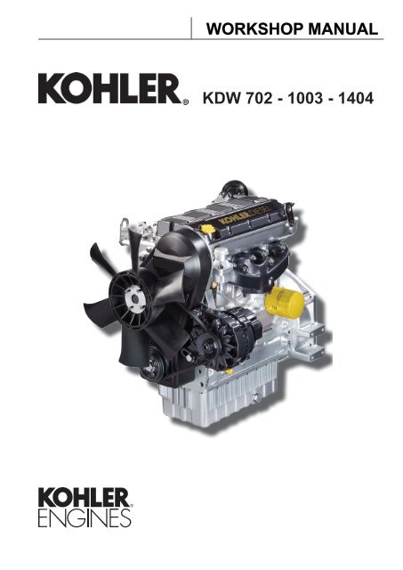
<strong>WORKSHOP</strong> <strong>MANUAL</strong><strong>KDW</strong> <strong>702</strong> - <strong>1003</strong> - <strong>1404</strong>
-- 2 - KD <strong>702</strong>_<strong>1003</strong>_<strong>1404</strong> Workshop Manual_cod. ED0053029340_1° ed_ rev. 00
-<strong>KDW</strong><strong>702</strong> - <strong>1003</strong> - <strong>1404</strong>PREFACE- Every attempt has been made to present within this service manual, accurate and up to date technical information.However, development on the KOHLER series is continuous.Therefore, the information within this manual is subject to change without notice and without obligation.The materials used by KOHLER to construct the engine's components undergo strict quality controls and the engine'sassembly guarantees reliability and long life.The engine has been built to the machine manufacturer's specifications, and it was its responsibility to adopt all the measuresneeded to meet the essential health and safety requirements as provided for by the laws in force; use of the engine for usesother than the one defined shall not be considered as compliant with the use intended by KOHLER, who therefore refuses allresponsibility for any injury arising from such an operation.- The information contained within this service manual is the sole property of KOHLER.As such, no reproduction or replication in whole or part is allowed without the express written permission of KOHLER.Information presented within this manual assumes the following:1 - The person or people performing service work on KOHLER series engines is properly trained and equipped to safely andprofessionally perform the subject operation;2 - The person or people performing service work on KOHLER series engines possesses adequate hand and KOHLER specialtools to safely and professionally perform the subject service operation;3 - The person or people performing service work on KOHLER series engines has read the pertinent information regarding thesubject service operations and fully understands the operation at hand.- This manual was written by the manufacturer to provide technical and operating information to authorised KOHLER after-salesservice centres to carry out assembly, disassembly, overhauling, replacement and tuning operations.- As well as employing good operating techniques and observing the right timing for operations, operators must read theinformation very carefully and comply with it scrupulously.- Time spent reading this information will help to prevent health and safety risks and financial damage.Written information is accompanied by illustrations in order to facilitate your understanding of every step of the operating phases.KD <strong>702</strong>_<strong>1003</strong>_<strong>1404</strong> Workshop Manual_cod. ED0053029340_1° ed_- 3 -
-REGISTRATION OF MODIFICATIONS TO THE DOCUMENTAny modifications to this document must be registered by the drafting body, by completing the following table.DraftingbodyDocumentcodeModelN°EditionRevisionIssue dateReviewdateEndorsedCUSE/ATLOED0053029340 512621° 0 20/06/2012 20/06/2012- 4 - KD <strong>702</strong>_<strong>1003</strong>_<strong>1404</strong> Workshop Manual_cod. ED0053029340_1° ed_ rev. 00
CHAPTER INDEX-This manual contains pertinent information regarding the repair of <strong>Kohler</strong> water-cooled, indirect injection Diesel engines type<strong>KDW</strong> <strong>702</strong>-<strong>1003</strong>-<strong>1404</strong>: updated 20/06/2012.CHAPTER INDEX1 - MANUFACTURER AND ENGINE IDENTIFICATION......................................................................................... 10The identification plate shown in the figure can be found directly on the engine..............................................................10Approval data.....................................................................................................................................................................10Name plate for EPA rules applied on rocker-arm cap........................................................................................................11Compilation example..........................................................................................................................................................112 - GENERAL REMARKS AND SAFETY INFORMATION..................................................................................... 12California emission control warranty statement.................................................................................................................13Your warranty rights and obligations..................................................................................................................................13Explanation of the safety pictograms that can be found on the engine or in the operationand maintenance handbook...............................................................................................................................................14Indications regarding the points on the engine where the safety pictograms are placed.................................................14Limited 3 year kohler ® diesel engine warranty..................................................................................................................15General service manual notes...........................................................................................................................................15Glossary and terminology..................................................................................................................................................15Safety regulations...............................................................................................................................................................16General safety during operating phases............................................................................................................................17Safety and environmental impact ......................................................................................................................................17Trouble shooting.................................................................................................................................................................183 - TECHNICAL INFORMATION..............................................................................................................................18Trouble shooting.................................................................................................................................................................18Techinical specifications.....................................................................................................................................................21Performance diagrams...................................................................................................................................................... 24Overall dimension.............................................................................................................................................................. 284 - MAINTENANCE - RECOMMENDED OIL TYPE - REFILLING......................................................................... 32Routine engine maintenance............................................................................................................................................. 32Ordinary maintenance ...................................................................................................................................................... 32Extraordinary maintenance .............................................................................................................................................. 32Lubricant............................................................................................................................................................................ 33Prescribed lubricant.......................................................................................................................................................... 34Coolant.............................................................................................................................................................................. 35Fuel recommendations...................................................................................................................................................... 355 - REGULATIONS FOR LIFTING THE ENGINE ................................................................................................ 366 - DISASSEMBLY / REASSEMBLY....................................................................................................................... 37Recommendations for disassembling and assembling..................................................................................................... 37Recommendations for overhauls and tuning.................................................................................................................... 37Dry type air filter................................................................................................................................................................ 38Air restriction switch.......................................................................................................................................................... 38Oil bath air cleaner (on request)........................................................................................................................................ 38Air filter support................................................................................................................................................................. 39Intake manifold – remote air filter...................................................................................................................................... 39E.G.R. Circuit (Components)............................................................................................................................................. 40E.G.R. Circuit.....................................................................................................................................................................41Vacuum pump and vacuum pump flange...........................................................................................................................42Exhaust manifold................................................................................................................................................................42Exhaust manifold - engines with egr..................................................................................................................................42Cooling fan........................................................................................................................................................................ 43Alternator/cooling fan belt drive......................................................................................................................................... 43KD <strong>702</strong>_<strong>1003</strong>_<strong>1404</strong> Workshop Manual_cod. ED0053029340_1° ed_- 5 -
- Chapter indexFuel tank (optional)............................................................................................................................................................ 43Flywheel............................................................................................................................................................................ 44Return pulley..................................................................................................................................................................... 44Driving pulley..................................................................................................................................................................... 44Ringfeder-type rings on kdw <strong>1404</strong>.................................................................................................................................... 45Ringfeder-type rings on kdw <strong>1404</strong> - assembly.................................................................................................................. 45Timing belt cover............................................................................................................................................................... 45Timing belt / timing pulley arrangement............................................................................................................................ 46Timing belt removal........................................................................................................................................................... 46Tightening pulley............................................................................................................................................................... 46Crankshaft timing pulley.................................................................................................................................................... 46Camshaft timing pulley.......................................................................................................................................................47Camshaft timing pulley - disassembly/assembly...............................................................................................................47Camshaft timing pulley - reference marks.........................................................................................................................47Camshaft timing.................................................................................................................................................................47Camshaft timing - belt reassembly ....................................................................................................................................47Camshaft timing - belt tightening tool................................................................................................................................ 48Camshaft timing - belt tightening and fastening................................................................................................................ 48Valve timing check............................................................................................................................................................. 48Valve timing - angles......................................................................................................................................................... 49Speed governor................................................................................................................................................................. 50Speed governor components............................................................................................................................................ 50Governor springs............................................................................................................................................................... 50Governor springs for gensets............................................................................................................................................ 50Speed governor - limiting speed governor.........................................................................................................................51Speed governor - reassembly............................................................................................................................................51Oil pump............................................................................................................................................................................ 52Oil pump - disassembly..................................................................................................................................................... 52Oil pump - reassembly...................................................................................................................................................... 52Rocker arm cover.............................................................................................................................................................. 52Rocker arm cover gasket................................................................................................................................................... 53Crankcase vacuum regulator valve................................................................................................................................... 53Crankcase breather........................................................................................................................................................... 54Valve / rocker arm clearance............................................................................................................................................. 54Injection pump control rod................................................................................................................................................. 54Fuel rail.............................................................................................................................................................................. 54Pump/injector unit - non-return valve................................................................................................................................ 55Pump/injector unit - disassembly...................................................................................................................................... 55Rocker arm pivot, dismounting and remounting............................................................................................................... 56Camshaft, disassembly..................................................................................................................................................... 56Camshaft, journal and housing measurement.................................................................................................................. 56Camshaft journals and housings - dimensions (mm)........................................................................................................ 57Camshaft lobe measurement............................................................................................................................................ 57Intake / exhaust / injection camshaft lobe height.............................................................................................................. 57Cylinder head, removal..................................................................................................................................................... 58Valves................................................................................................................................................................................ 58Valve stem sealing rings - reassembly.............................................................................................................................. 58Valve springs..................................................................................................................................................................... 58Valve, specifications.......................................................................................................................................................... 59Valve guides and valve guide housings............................................................................................................................ 59Valve guide insertion......................................................................................................................................................... 59Valve seats and housings - dimensions............................................................................................................................ 60Valve recess and seat sealing width................................................................................................................................. 60Pre-combustion chamber ..................................................................................................................................................61Pre-combustion chamber ring nut removal........................................................................................................................61Pre-combustion chamber, removal....................................................................................................................................61Pre-combustion chamber, installation................................................................................................................................61Oil pan, removal................................................................................................................................................................ 62Piston................................................................................................................................................................................. 62Stop pin rings, dismounting and remounting..................................................................................................................... 62Piston, disassembly and inspection.................................................................................................................................. 63Piston, class...................................................................................................................................................................... 63Piston, weight.................................................................................................................................................................... 64Piston rings - end gaps (mm)............................................................................................................................................ 64Piston ring, clearance between grooves (mm).................................................................................................................. 64Piston ring, mounting order............................................................................................................................................... 65Piston, assembly............................................................................................................................................................... 65- 6 - KD <strong>702</strong>_<strong>1003</strong>_<strong>1404</strong> Workshop Manual_cod. ED0053029340_1° ed_ rev. 00
Chapter index-Piston clearance................................................................................................................................................................ 65Head gasket...................................................................................................................................................................... 66Cylinder head assembly.................................................................................................................................................... 67Cylinder head tightening procedure <strong>KDW</strong> <strong>1003</strong>............................................................................................................... 67Cylinder head tightening procedure <strong>KDW</strong> <strong>1404</strong>................................................................................................................ 67Connecting rod.................................................................................................................................................................. 68Big end bearing................................................................................................................................................................. 68Connecting tod, weight...................................................................................................................................................... 68Connecting rod with bearings and pin............................................................................................................................... 68Connecting rod alignment................................................................................................................................................. 69Cylinders........................................................................................................................................................................... 69Cylinder, class................................................................................................................................................................... 69Cylinder roughness........................................................................................................................................................... 69Central main bearing caps................................................................................................................................................ 70Rear and forward main bearing caps................................................................................................................................ 70Check the clearances between the bearings and the journal........................................................................................... 70Piston coolant nozzles.......................................................................................................................................................71Shoulder half rings.............................................................................................................................................................71Crankshaft axial clearance.................................................................................................................................................71Shoulder half rings, oversized elements........................................................................................................................... 72Crankshaft front and back oil seal rings............................................................................................................................ 72Crankshaft, lubrication lines.............................................................................................................................................. 73Crankshaft, check journals and crank............................................................................................................................... 73Journal and connecting rod pins diameters...................................................................................................................... 73Main bearings and connecting rod big ends diameters.....................................................................................................74Clearances between the bearings and corresponding pins..............................................................................................74Hydraulic pump drive..........................................................................................................................................................75Third drive, components.....................................................................................................................................................757 - TURBOCHARGER.............................................................................................................................................. 76Turbo charger.....................................................................................................................................................................76Turbocharger components.................................................................................................................................................76Turbocharger pressure testing...........................................................................................................................................76Turbocharger west gate adjustment - regolazione corsa asta comando valvola " waste gate "....................................... 778 - LUBRIFICATION CIRCUIT..................................................................................................................................78Lubrification circuit............................................................................................................................................................ 78Internal oil filter and oil sump return pipe.......................................................................................................................... 79Oil pump ........................................................................................................................................................................... 79Oil pump, clearance between rotors................................................................................................................................. 79Oil pressure regulating valve............................................................................................................................................. 80Oil filter cartridge............................................................................................................................................................... 80Oil pressure check............................................................................................................................................................. 809 - COOLANT CIRCUIT............................................................................................................................................82Coolant circuit.................................................................................................................................................................... 82Radiator and compensation, check and seal tank cap..................................................................................................... 83Coolant circulation pump, components............................................................................................................................. 83Thermostatic valve............................................................................................................................................................ 8310 - FUEL SYSTEM.................................................................................................................................................. 84Fuel feeding / injection circuit ........................................................................................................................................... 84Fuel filter detached from the tank (on request)................................................................................................................. 84Fuel lift pump..................................................................................................................................................................... 84Fuel pump drive rod projection.......................................................................................................................................... 84Pump/injector unit.............................................................................................................................................................. 85Pump/injector unit, components........................................................................................................................................ 85Plunger barrel ring nut assembly/disassembly................................................................................................................. 86Injection pump assembly/disassembly.............................................................................................................................. 86Plunger injection pump reassembly.................................................................................................................................. 86KD <strong>702</strong>_<strong>1003</strong>_<strong>1404</strong> Workshop Manual_cod. ED0053029340_1° ed_- 7 -
- Chapter indexPumping element (old-type injection pump)...................................................................................................................... 87Pumping element............................................................................................................................................................... 87Pump/injector unit se.No. 6590.285 Control data............................................................................................................. 87Injector, setting (old type).................................................................................................................................................. 89Setting of injector according to current pump/injector unit............................................................................................... 89Injector, nozzle projection................................................................................................................................................. 89Injector, spark arrester...................................................................................................................................................... 89Injection advance control and regulation.......................................................................................................................... 90Injection advance for currently used pump/injector unit................................................................................................... 90Static injection advance tuning...........................................................................................................................................91Injection advance references on timing belt protector.......................................................................................................91Tdc (top dead center) references.......................................................................................................................................91Tester and special coupling for injection advance control (old-type injection pump)........................................................91Static injection advance regulation .................................................................................................................................. 92Preliminary steps to pump/injector unit delivery balancing test........................................................................................ 92Closing the oilhole............................................................................................................................................................. 92Test head b assembly........................................................................................................................................................ 92Instrument connection....................................................................................................................................................... 93Injection pumps delivery balancing................................................................................................................................... 93Electric control panel with automatic engine stop (Upon request).................................................................................... 9411 - ELECTRIC SYSTEM......................................................................................................................................... 94Alternator, 14v 33a........................................................................................................................................................... 95Alternator, 14v 33a - performance curve......................................................................................................................... 95Electric starting layout (12v) with alternator 14v 33a........................................................................................................ 96Alternator 14v 45a - 65a................................................................................................................................................... 97Alternator, 14v 45a - performance curve......................................................................................................................... 97Alternator, 14v 65a - performance curve......................................................................................................................... 97Electric starting layout 12v 33a - 45a - 65a....................................................................................................................... 98Flywheel alternator............................................................................................................................................................ 98Alternator battery charger curve 12v 30a......................................................................................................................... 99(Two cables at output)....................................................................................................................................................... 99Electric starting layout (12v) with flywheel alternator...................................................................................................... 100Voltage regulator connections......................................................................................................................................... 100Starter motor - bosch dw 12v 1,1 kw...............................................................................................................................101Starter motor, bosch dw 12v 1,1 kw - performance curve..............................................................................................101Starter motor, bosch 12v 1,6 kw.......................................................................................................................................101Starter motor, bosch dw 12v 1,6 kw - performance curve..............................................................................................102Pre-heating glow plug......................................................................................................................................................102Pre-heating plug control unit with coolant temperature sensor.......................................................................................102Temperature sensor for control unit.................................................................................................................................103Oil pressure switch (fig. 215)............................................................................................................................................103Pre-heating water temperature thermistor and water temperature indicator thermal contact.........................................10312 - SETTINGS....................................................................................................................................................... 104Speed settings................................................................................................................................................................. 104Setting the idle minimum (standard)............................................................................................................................... 104Setting the idle maximum (standard).............................................................................................................................. 104Pump injection delivery standard setting without dynamometric brake.......................................................................... 104Injection pump flow limiter and engine torque gearing device........................................................................................ 105Pump/injector unit timing with speed governor............................................................................................................... 105Pump/injector unit delivery setting with braked engine................................................................................................... 106E.G.R. Calibration............................................................................................................................................................10713 - STORAGE....................................................................................................................................................... 108Engine storage ............................................................................................................................................................... 108Protective treatment........................................................................................................................................................ 108Preparing the engine for operation after protective treatment........................................................................................ 109- 8 - KD <strong>702</strong>_<strong>1003</strong>_<strong>1404</strong> Workshop Manual_cod. ED0053029340_1° ed_ rev. 00
Chapter index-14 - TORQUE SPECIFICATIONS AND USE OF SEALANT.................................................................................110Table of tightening torques for the main components......................................................................................................110Table of tightening torques for standard screws (coarse thread)..................................................................................... 111Table of tightening torques for standard screws (fine thread).......................................................................................... 11115 - SPECIAL TOOLS.............................................................................................................................................112KD <strong>702</strong>_<strong>1003</strong>_<strong>1404</strong> Workshop Manual_cod. ED0053029340_1° ed_- 9 -
1 MANUFACTURER AND ENGINE IDENTIFICATIONThe identification plate shown in the figure can be found directly on the engine.It contains the following information:A) Manufacturer’s identityB) Engine typeC) Engine serial numberD) Maximum operating speedE) Number of the customer version (form K)F) Approval dataApproval dataThe approval reference directives EC are on the engine plate (F).ABDCEF- 10 - KD <strong>702</strong>_<strong>1003</strong>_<strong>1404</strong> Workshop Manual_cod. ED0053029340_1° ed_ rev. 00
MANUFACTURER AND ENGINE IDENTIFICATION1Name plate for EPA rules applied on rocker-arm capCompilation example13 102 45USE IN CONSTANT-SPEED APPLICATIONS ONLY 67891) Model year.2) Engine displacement.3) Power category, kW.4) Particulate emission limit (g/kWh).5) Engine family ID.6) Kind of application i.e.7) Injection timing (BTDC).8) Injector opening pressure (bar).9) Production date (example 2012_Jan).10) Emission Control System = ECS.KD <strong>702</strong>_<strong>1003</strong>_<strong>1404</strong> Workshop Manual_cod. ED0053029340_1° ed_- 11 -
2 GENERAL REMARKS AND SAFETY INFORMATIONTo ensure safe operation please read the following statements and understand their meaning. Also refer to your equipment manufacturer's manualfor other important safety information. This manual contains safety precautions which are explained below.Danger – AttentionThis indicates situations of grave danger which, if ignored, may seriously threaten the health and safety of individuals.Caution – WarningThis indicates that it is necessary to take proper precautions to prevent any risk to the health and safety of individuals and avoid financialdamage.ImportantThis indicates particularly important technical information that should not be ignored.SAFETY REGULATIONSDANGER DANGER DANGERAccidental Starts can causesevere injury or death.Disable engine by disconnectingnegative (-) battery cable.Accidental Starts!Disabling engine. Accidental startingcan cause severe injury or death.Before working on the engine orequipment, disable the engine asfollows: 1) Disconnect negative (-)battery cable from battery.Rotating Parts can cause severeinjury.Stay away while engine is inoperation.Rotating Parts!Keep hands, feet, hair, and clothingaway from all moving parts to preventinjury. Never operate the engine withcovers, shrouds, or guards removed.Carbon Monoxide can causesevere nausea, fainting or death.Avoid inhaling exhaust fumes, andnever run the engine in a closedbuilding or confined area.Lethal Exhaust Gases!Engine exhaust gases containpoisonous carbon monoxide. Carbonmonoxide is odorless, colorless, andcan cause death if inhaled. Avoidinhaling exhaust fumes, and neverrun the engine in a closed building orconfined area.DANGER DANGERDANGERHot Parts can cause severeburns.Do not touch engine while operatingor just after stopping.Hot Parts!Engine components can getextremely hot from operation. Toprevent severe burns, do not touchthese areas while the engine isrunning, or immediately after it isturned off. Never operate the enginewith heat shields or guards removed.Fuel can cause fires and severeburns.Do not fill the fuel tank while theengine is hot or running.Explosive Fuel!Fuel is flammable and its vapors canignite. Store fuel only in approvedcontainers, in well ventilated,unoccupied buildings. Do not fill thefuel tank while the engine is hot orrunning, since spilled fuel could igniteif it comes in contact with hot parts orsparks from ignition. Do not start theengine near spilled fuel. Never usefuel as a cleaning agent.Explosive Gas can cause firesand severe acid burns.Charge battery only in a wellventilated area. Keep sources ofignition away.Explosive Gas!Batteries produce explosivehydrogen gas while being charged.To prevent a fire or explosion, chargebatteries only in well ventilated areas.Keep sparks, open flames, and othersources of ignition away from thebattery at all times. Keep batteriesout of the reach of children. Removeall jewelry when servicing batteries.Before disconnecting the negative (-)ground cable, make sure all switchesare OFF. If ON, a spark will occurat the ground cable terminal whichcould cause an explosion if hydrogengas or fuel vapors are present.- 12 - KD <strong>702</strong>_<strong>1003</strong>_<strong>1404</strong> Workshop Manual_cod. ED0053029340_1° ed_ rev. 00
General remarks and safety information2DANGERCAUTIONHigh Pressure Fluids canpuncture skin and cause severeinjury or death.Do not work on fuel system withoutproper training or safety equipment.H i g h P r e s s u r e F l u i dPuncture!Fuel system is to be serviced only byproperly trained personnel wearingprotective safety equipment. Fluidpuncture injuries are highly toxic andhazardous. If an injury occurs, seekimmediate medical attention.Electrical Shock can causeinjury.Do not touch wires while engine isrunning.Electrical Shock!Never touch electrical wires orcomponents while the engine isrunning. They can be sources ofelectrical shock.California Proposition 65WARNINGEngine exhaust from this product containschemicals known to the State of California to causecancer, birth defects, or other reproductive harm.CALIFORNIA EMISSION CONTROL WARRANTY STATEMENTYOUR WARRANTY RIGHTS AND OBLIGATIONSThe California Air Resources Board and <strong>Kohler</strong> Co. are pleased to explain the emission control system warranty on your 2012 engine. InCalifornia, new heavy-duty off-road engines must be designed, built and equipped to meet the State’s stringent anti-smog standards. <strong>Kohler</strong> Co.must warrant the emission control system on your engine for the time period listed below provided there has been no abuse, neglect or impropermaintenance of your engine.Your emission control system may include parts such as the fuel-injection system and the air induction system. Also included may be hoses,connectors and other emission related assemblies.Where a warrantable condition exists, <strong>Kohler</strong> Co. will repair your heavy-duty off-road engine at no cost to you including diagnosis, parts and labor.MANUFACTURER’S WARRANTY COVERAGE:Your off-road, diesel engine emission control system is covered under warranty for a period of five (5) years or 3,000 hours, whichever occurs first,beginning on the date the engine or equipment is delivered to an ultimate purchaser for all constant speed engines with maximum power 19≤kW
2General remarks and safety informationExplanation of the safety pictograms that can be found on the engine or in the Operation and Maintenance handbookRead the Operation and Maintenance handbook beforeperforming any operation on the engineUse protective gloves before carrying out the operationUse protective glasses before carrying out the operationHigh temperature components - Danger of scaldingUse sound absorbing protections before carrying out the operationPresence of rotating parts - Danger of entangling and cuttingElectric shock - Danger of severe scalding or deathFluids under high pressure - Danger of fluids penetrationPresence of explosive fuel - Danger of fire or explosionLethal exhaust gas - Danger of poisoning or deathPresence of steam and pressurized coolant - Danger of scaldingIndications regarding the points on the engine where the safety pictograms are placed- 14 - KD <strong>702</strong>_<strong>1003</strong>_<strong>1404</strong> Workshop Manual_cod. ED0053029340_1° ed_ rev. 00
General remarks and safety information2LIMITED 3 YEAR KOHLER ® DIESEL ENGINE WARRANTY<strong>Kohler</strong> Co. warrants to the original retail consumer that each new KOHLER Diesel engine sold by <strong>Kohler</strong> Co. will be free from manufacturingdefects in materials or workmanship in normal service for a period of three (3) years or 2000 hours whichever occurs first from the date ofpurchase, provided it is operated and maintained in accordance with <strong>Kohler</strong> Co.’s instructions and manuals. If no hour meter is installed as originalequipment then 8 hours of use per day and 5 days per week will be used to calculate hours used.Our obligation under this warranty is expressly limited, at our option, to the replacement or repair at <strong>Kohler</strong> Co., <strong>Kohler</strong>, Wisconsin 53044, or at aservice facility designated by us of such parts as inspection shall disclose to have been defective.This warranty does not apply to defects caused by unreasonable use, including faulty repairs by others and failure to provide reasonable andnecessary maintenance.The following items are not covered by this warranty:Engine accessories such as fuel tanks, clutches, transmissions, power-drive assemblies and batteries, unless supplied or installed by <strong>Kohler</strong> Co.These are subject to the warranties, if any, of their manufacturers.KOHLER CO. AND/OR THE SELLER SHALL NOT BE LIABLE FOR SPECIAL, INDIRECT, INCIDENTIAL OR CONSEQUENTIAL DAMAGESOF ANY KIND, including but not limited to labor costs or transportation charges in connection with the repair or replacement of defective parts.IMPLIED OR STATUTORY WARRANTIES, INCLUDING WARRANTIES OF MERCHANTABILITY OR FITNESS FOR A PARTICULAR PURPOSE,ARE EXPRESSLY LIMITED TO THE DURATION OF THIS WRITTEN WARRANTY. We make no other express warranty, nor is any one authorizedto make any on our behalf.Some states do not allow limitations on how long an implied warranty lasts, or the exclusion or limitation of incidental or consequential damages,so the above limitation or exclusion may not apply to you.This warranty gives you specific legal rights, and you may also have other rights, which vary from state to state.To obtain warranty servicePurchaser must bring the engine to an authorized <strong>Kohler</strong> service facility. To locate the nearest facility, visit our website, www.kohlerengines.com,and use the locator function, consult your Yellow Pages or telephone 1-800-544-2444.ENGINE DIVISION, KOHLER CO., KOHLER, WISCONSIN 53044GENERAL SERVICE <strong>MANUAL</strong> NOTES1 - Use only genuine <strong>Kohler</strong> repair parts.Failure to use genuine <strong>Kohler</strong> parts could result in substandardperformance and low longevity.2 - All data presented are in metric format. That is, dimensionsare presented in millimeters (mm), torque is presented inNewton-meters (Nm), weight is presented in kilograms(Kg), volume is presented in liters or cubic centimeters (cc)and pressure is presented in barometric units (bar).GLOSSARY AND TERMINOLOGYFor clarity, here are the definitions of a number of terms usedrecurrently in the manual.- Cylinder number one: is the piston timing belt side «viewedfrom the flywheel side of the engine».- Rotation direction: anticlockwise «viewed from the flywheelside of the engine».KD <strong>702</strong>_<strong>1003</strong>_<strong>1404</strong> Workshop Manual_cod. ED0053029340_1° ed_- 15 -
2 General remarks and safety informationSAFETY REGULATIONSGENERAL NOTES. <strong>Kohler</strong> engines are built to provide safe and longlastingperformances, but in order to obtain these results it isessential that the maintenance requirements described inthe manual are observed along with the following safetyrecommendations.. The engine has been built to the specifications of amachine manufacturer, and it is his responsibility to ensurethat all necessary action is taken to meet the essentialand legally prescribed health and safety requirements.Any use of the machine other than that described cannotbe considered as complying with its intended purposeas specified by <strong>Kohler</strong>, which therefore declines allresponsibility for accidents caused by such operations.. The following instructions are intended for the user of themachine in order to reduce or eliminate risks, especiallythose concerning the operation and standard maintenanceof the engine.. The user should read these instructions carefully and getto know the operations described. By not doing so he mayplace at risk his own health and safety and that of anyoneelse in the vicinity of the machine.. The engine may be used or mounted on a machine onlyby personnel suitably trained in its operation and aware ofthe dangers involved. This is particularly true for standardand, above all, special maintenance work. For specialmaintenance contact personnel trained specifically by<strong>Kohler</strong>. This work should be carried out in accordance withexisting literature.. <strong>Kohler</strong> declines all responsibility for accidents or for failureto comply with the requirements of law if changes are madeto the engine’s functional parameters or to the fuel flow rateadjustments and speed of rotation, if seals are removed,or if parts not described in the operating and maintenancemanual are removed and reassembled by unauthorizedpersonnel.WARNING. In addition to all other machine specifications, ensure thatthe engine is in a near horizontal position when starting. lfstarting manually, ensure that the necessary operationscan be performed without any risk of striking against wallsor dangerous objects. Rope starting (except for recoil ropestarting) is not permitted even in emergencies.. Check that the machine is stable so that there is no risk of itoverturning.. Get to know the engine speed adjustment and machinestop operations.. Do not start the machine in closed or poorly ventilatedenvironments. The internal combustion process generatescarbon monoxide, an odourless and highly toxic gas, sospending too long a time in an environment where theengine discharges its exhaust products freely can lead toloss of consciousness and even death.. The engine may not be used in environments containingflammable materials, explosive atmospheres or easilycombustible powders, unless adequate and specificprecautions have been taken and are clearly stated andcertified for the machine.. To prevent the risk of fire, keep the machine at a distance ofat least one metre from buildings or other machines.. Children and animals must be kept at a sufficient distancefrom the machine to prevent any danger resulting from itsoperation.. Fuel is flammable, so the tank must be filled only when theengine is turned off. Dry carefully any fuel that may havespilled, remove the fuel container and any cloths soakedin fuel or oil, check that any sound-absorbing panels madeof porous material are not soaked with fuel or oil, and makesure that the ground on which the machine is located has notabsorbed fuel or oil.. Before starting, remove any tools that have been used forcarrying out maintenance work to the engine and/or themachine and check that any guards removed have beenreplaced. In cold climates it is possible to mix kerosene withthe diesel fuel to make the engine easier to start. The liquidsmust be mixed in the tank by pouring in first the keroseneand then the diesel fuel. Consult <strong>Kohler</strong> technical office formixture proportions. Petrol may not be used because of therisk of it forming flammable vapours.. During operation the surface of the engine reachestemperatures that may be dangerous. Avoid in particular allcontact with the exhaust system.. The liquid cooling circuit is under pressure. Do not carry outany checks before the engine has cooled down, and eventhen open the radiator cap or the expansion tank cautiously.Wear protective clothing and glasses. lf there is an electricfan, do not approach the engine while it is still hot as the fanmay come on even when the engine is not running. Clean thecooling system with the engine turned off.. While cleaning the oil bath air filter, check that the oil isdisposed of in such a way as not to harm the environment.Any filtering sponges in the oil bath air filter should not besoaked with oil. The cyclone pre-filter cup must not be filledwith oil.. Since the oil must be emptied out while the engine is still hot(approx. 80°C), particular care should be taken in order toavoid burns. In any case make sure that oil does not comeinto contact with your skin because of the health hazardsinvolved.. Fuel vapours are highly toxic, so fill up only in the open air orin well ventilated environments.. During operations which involve access to moving parts ofthe engine and/or removal of the rotary guards, disconnectand insulate the positive cable of the battery so as to preventaccidental short circuits and activation of the starter motor.. Check the belt tension only when the engine is turned off.IMPORTANT. To start the engine follow the specific instructions providedin the engine and/or machine operating manual. Do notuse auxiliary starting devices not originally installed on themachine (e.g. Startpilot systems which utilise ether etc.). Before carrying out any work on the engine, turn it off andallow it to cool down. Do not perform any operation while theengine is running.. Check that the discharged oil, the oil filter and the oilcontained in the oil filter are disposed of in such a way as notto harm the environment.. Close the fuel tank filler cap carefully after each fíllingoperation. Do not fill the tank right up to the top, but leavesufficient space to allow for any expansion of the fuel.. Do not smoke or use naked flames while filling.- 16 - KD <strong>702</strong>_<strong>1003</strong>_<strong>1404</strong> Workshop Manual_cod. ED0053029340_1° ed_ rev. 00
General remarks and safety information2. Take care when removing the oil filter as it may be hot.. The operations of checking, filling up and replacing thecooling liquid must be carried out with the engine turned offand cold. Take particular care if liquids containing nitritesare mixed with others not containing these compoundsas this may give rise to the formation of nitrosamineswhich are a health hazard. The cooling liquid is polluting,so dispose of in a manner that does not damage theenvironment.. In order to move the engine simultaneously use theeyebolts fitted for this purpose by <strong>Kohler</strong>. These liftingpoints are however not suitable for the entire machine, soin this case use the eyebolts fitted by the manufacturer.GENERAL SAFETY DURING OPERATING PHASES– The procedures contained in this manual have beentested and selected by the manufacturer’s technicalexperts, and hence are to be recognised as authorisedoperating methods.– Some tools are normal workshop ones, while others arespecial tools designed by the Manufacturer of the engine.– All tools must be in good working condition so that enginecomponents are not damaged and that operations arecarried out properly and safely.– It is important to wear the personal safety devicesprescribed by work safety laws and also by the standardsof this manual.– Holes must be lined up methodically and with the aid ofsuitable equipment. Do not use your fingers to carry outthis operation to avoid the risk of amputation.– Some phases may require the assistance of more thanone operator. If so, it is important to inform and train themregarding the type of activity they will be performing inorder to prevent risks to the health and safety of all personsinvolved.– Do not use flammable liquids (petrol, diesel, etc.) todegrease or wash components. Use special products.– Use the oils and greases recommended by the manufacturer.Do not mix different brands or combine oils with differentcharacteristics.– Discontinue use of the engine if any irregularities arise,particularly in the case of unusual vibrations.– Do not tamper with any devices to alter the level ofperformance guaranteed by the manufacturer.SAFETY AND ENVIRONMENTAL IMPACTEvery organisation has a duty to implement procedures to identify,assess and monitor the influence of its own activities (products,services, etc.) on the environment.Procedures for identifying the extent of the impact on the environmentmust consider the following factors:- Liquid waste;- Waste management;- Soil contamination;- Atmospheric emissions;- Use of raw materials and natural resources;- Regulations and directives regarding environmental impact.In order to minimise the impact on the environment, the manufacturernow provides a number of indications to be followed by all personshandling the engine, for any reason, during its expected lifetime.- All packaging components must be disposed of in accordancewith the laws of the country in which disposal is taking place.- Keep the fuel and engine control systems and the exhaustpipes in efficient working order to limit environmental and noisepollution.- When discontinuing use of the engine, select all componentsaccording to their chemical characteristics and dispose of themseparately.KD <strong>702</strong>_<strong>1003</strong>_<strong>1404</strong> Workshop Manual_cod. ED0053029340_1° ed_- 17 -
3TECHNICAL INFORMATIONTROUBLE SHOOTINGTHE ENGINE MUST BE STOPPED IMMEDIATELY WHEN:1) - The engine rpms suddenly increase and decrease;2) - A sudden and unusual noise is heard;3) - The colour of the exhaust fumes suddenly darkens;4) - The oil pressure indicator light turns on while running.TABLE OF LIKELY ANOMALIES AND THEIR SYMPTOMSThe following table contains the possible causes of some failures which may occur during operation.Always perform these simple checks before removing or replacing any part.TROUBLEPOSSIBLE CAUSEEngine does not startEngine starts but stopsNo accelerationNon-uniform speedBlack smokeWhite smokeOil preassure too lowOil level increaseExcessive oil consumptionOil and fuel drippingfrom the exhaustEngine overheatsInadequate performanceHigh noise levelClogged fuel pipesClogged fuel filterFUELCIRCUITELECTRICSYSTEMMAINTENAN-CESETTINGS REPAIRSAir or water in the fuel circuitTank cap breather blockedFaulty fuel pumpLack of fuelGlow plug fuse burnedFaulty glow plug control relayFlat batteryUnclear or mistaken cable connectionFaulty starter switchFaulty starting motorFaulty glow plugsClogged air filterProlonged operation at idleIncomplete run-inOverloaded engineExcessive valve clearancesAbsence of valve clearancesIncorrect speed governor leveragesSpeed governor spring broken or disengagedIdle lowWorn out or stuck ringsWorn out cylindersWorn out valve guidesBad valve sealBearing shells of bearing cap - piston rod - rocker worn outE.G.R. valve blocked openGovernor leverages not runningCylinder head gasket damagedFaulty timing systemSupplementary starter spring broken or disengaged- 18 - KD <strong>702</strong>_<strong>1003</strong>_<strong>1404</strong> Workshop Manual_cod. ED0053029340_1° ed_ rev. 00
Technical information3TROUBLEPOSSIBLE CAUSEEngine does not startEngine starts but stopsNo accelerationNon-uniform speedBlack smokeWhite smokeOil preassure too lowOil level increaseExcessive oil consumptionOil and fuel drippingfrom the exhaustEngine overheatsInadequate performanceHigh noise levelHigh oil levelLow oil levelLUBRICATIONCIRCUITINJECTIONCOOLINGCIRCUITDirty or blocked pressure regulation valveWorn oil pumpAir to the oil suction hoseFaulty manometer or pressure switchOil in sump suction hose blockedOil in sump drainage pipe blockedFaulty spray nozzles (Turbo engines only)Damaged injectorDamaged injection pump valveIncorrectly calibrated injectorWorn or damaged pumping elementIncorrect injection pump delivery setting (delivery equalisation)Hardened pump/injector control rodCracked or broken pre-combustion chamberIncorrect adjustment of the injection systems (delivery equalisationadvance)Insufficient refrigerant fluidDefective fan, radiator, or radiator capDefective thermostatic valveLoss of refrigerant fluid from the radiator, hoses, engine crankshaftor water pump.Inside of radiator or coolant lines obstructed.Defective or worn water pumpAlternator fan drive belt loose or tornHeat exchange surface of the radiator cloggedKD <strong>702</strong>_<strong>1003</strong>_<strong>1404</strong> Workshop Manual_cod. ED0053029340_1° ed_- 19 -
3 Technical information.............................................................................................................................................................................................................................................................................................................................................................................................................................................................................................................................................................................................................................................................................................................................................................................................................................................................................................................................................................................................................................................................................................................................................................................................................................................................................................................................................................................................................................................................................................................................................................................................................................................................................................................................................................................................................................................................................................................................................................................................................................................................................................................................................................................................................................................................................................................................................................................................................................................................................................................................................................................................................................................................................................................................................................................................................................................................................................................................................................................................................................................................................................................................................................................................................................................................................................................................................................................................................................................................................................................................................................................................................................................................................................................................................................................................................................................................................................................................................................................................................................................................................................................................................................................................................................................................................................................................................................................................................................................................................................................................................................................................................................................................................................................................................................................................................................................................................................................................................................................................................................................................................................................................................................................................................................................................................................................................................................................................................................................................................................................................................................................................................................................................................................................................................................................................................................................................................................................................................................................................................................................................................................................................................................................................................................................................................................................................................................................................................................................................................................................- 20 - KD <strong>702</strong>_<strong>1003</strong>_<strong>1404</strong> Workshop Manual_cod. ED0053029340_1° ed_ rev. 00
Technical information3TECHINICAL SPECIFICATIONSCylindersBoreStrokeDisplacementsCompression rateRpm<strong>KDW</strong><strong>702</strong><strong>KDW</strong><strong>1003</strong><strong>KDW</strong><strong>1404</strong>N° 2 3 4mm 75 75 75mm 77.6 77.6 77.6Cm 3 686 1028 137222,8:1 22,8:1 22,8:13600 3600 3600N 80/1269/CEE-ISO 1585 12.5(17.0) 19.5(26.5) 26.0(35.2)Maximum NB ISO 3046 - IFN 11.7(16) 18(24.5) 24.5(33.3)power NA ISO 3046 - ICXN 10.7(14.5) 16.5(22.4) 22.4(30.5)Maximum torque *Nm 40.5 67.0 84.0Maximum Torque Available @ N° 3 PTO 3600 RpmSpecific fuel consumption**Oil consumption ***Dry weight of engineCombustion air volume at 3600 RpmCooling air volume at 3600 RpmAxial load allowed on crankshaft (both directions)Instant operation (up to 1 min)Max tiltIntermittent operation (up to 30 min)Permanent operation* At NB power** Referred to NB power*** Measured at NA power**** Depends on application• At 3600 Rpm•• Measured at NB powerENGINE TYPE<strong>KDW</strong> <strong>702</strong>RPM @ 2000 @2000 @ 2000Nm 37@1800 37@1800 37@1800g/KWh 320 300 325Kg/h 0,009 0,013 0,019Kg 66 87 98l./1' 1240 1850 2470m 3 /mm 43 63 88Kg 300 300 300a 35° 35° 35°a 25° 25° 25°a **** **** ****<strong>KDW</strong> <strong>1003</strong> <strong>KDW</strong> <strong>1404</strong>KD <strong>702</strong>_<strong>1003</strong>_<strong>1404</strong> Workshop Manual_cod. ED0053029340_1° ed_- 21 -
3 Technical information.............................................................................................................................................................................................................................................................................................................................................................................................................................................................................................................................................................................................................................................................................................................................................................................................................................................................................................................................................................................................................................................................................................................................................................................................................................................................................................................................................................................................................................................................................................................................................................................................................................................................................................................................................................................................................................................................................................................................................................................................................................................................................................................................................................................................................................................................................................................................................................................................................................................................................................................................................................................................................................................................................................................................................................................................................................................................................................................................................................................................................................................................................................................................................................................................................................................................................................................................................................................................................................................................................................................................................................................................................................................................................................................................................................................................................................................................................................................................................................................................................................................................................................................................................................................................................................................................................................................................................................................................................................................................................................................................................................................................................................................................................................................................................................................................................................................................................................................................................................................................................................................................................................................................................................................................................................................................................................................................................................................................................................................................................................................................................................................................................................................................................................................................................................................................................................................................................................................................................................................................................................................................................................................................................................................................................................................................................................................................................................................................................................................................................................................- 22 - KD <strong>702</strong>_<strong>1003</strong>_<strong>1404</strong> Workshop Manual_cod. ED0053029340_1° ed_ rev. 00
Technical information3.............................................................................................................................................................................................................................................................................................................................................................................................................................................................................................................................................................................................................................................................................................................................................................................................................................................................................................................................................................................................................................................................................................................................................................................................................................................................................................................................................................................................................................................................................................................................................................................................................................................................................................................................................................................................................................................................................................................................................................................................................................................................................................................................................................................................................................................................................................................................................................................................................................................................................................................................................................................................................................................................................................................................................................................................................................................................................................................................................................................................................................................................................................................................................................................................................................................................................................................................................................................................................................................................................................................................................................................................................................................................................................................................................................................................................................................................................................................................................................................................................................................................................................................................................................................................................................................................................................................................................................................................................................................................................................................................................................................................................................................................................................................................................................................................................................................................................................................................................................................................................................................................................................................................................................................................................................................................................................................................................................................................................................................................................................................................................................................................................................................................................................................................................................................................................................................................................................................................................................................................................................................................................................................................................................................................................................................................................................................................................................................................................................................................................................................KD <strong>702</strong>_<strong>1003</strong>_<strong>1404</strong> Workshop Manual_cod. ED0053029340_1° ed_- 23 -
3 Technical informationPERFORMANCE DIAGRAMS<strong>KDW</strong> <strong>702</strong> <strong>KDW</strong> <strong>1003</strong><strong>KDW</strong> <strong>1404</strong>N (DIN 70020) Automotive rating, intermittent operation with variable speed and variable load.NB (DIN 6270) Rating with no overload capability, continuous light duty operation with constant speed and variable load.NA (DIN 6270) Continuous rating with overload capability, continuous heavy duty with constant speed and constant load.C (NB) : Specific fuel consumption at NB powerMt : Torque at N.a : Range of application for continuous operation. In case of application outside this range please contact KOHLER.The above power values refer to an engine fitted with air cleaner and standard muffler, after testing and at the environmentalconditions of 20°C and 1 bar. Max. power tolerance is 5%. Power decreases by approximately 1% every 100 m di altitudeand by 2% every 5°C above 25°C.Note: Consult KOHLER for power, torque curves and specific consumptions at rates differing from those given above.ImportantNon-approval by KOHLER for any modifications releases the company from any damages incurred by the engine.- 24 - KD <strong>702</strong>_<strong>1003</strong>_<strong>1404</strong> Workshop Manual_cod. ED0053029340_1° ed_ rev. 00
Technical information3.............................................................................................................................................................................................................................................................................................................................................................................................................................................................................................................................................................................................................................................................................................................................................................................................................................................................................................................................................................................................................................................................................................................................................................................................................................................................................................................................................................................................................................................................................................................................................................................................................................................................................................................................................................................................................................................................................................................................................................................................................................................................................................................................................................................................................................................................................................................................................................................................................................................................................................................................................................................................................................................................................................................................................................................................................................................................................................................................................................................................................................................................................................................................................................................................................................................................................................................................................................................................................................................................................................................................................................................................................................................................................................................................................................................................................................................................................................................................................................................................................................................................................................................................................................................................................................................................................................................................................................................................................................................................................................................................................................................................................................................................................................................................................................................................................................................................................................................................................................................................................................................................................................................................................................................................................................................................................................................................................................................................................................................................................................................................................................................................................................................................................................................................................................................................................................................................................................................................................................................................................................................................................................................................................................................................................................................................................................................................................................................................................................................................................................................KD <strong>702</strong>_<strong>1003</strong>_<strong>1404</strong> Workshop Manual_cod. ED0053029340_1° ed_- 25 -
3 Technical information.............................................................................................................................................................................................................................................................................................................................................................................................................................................................................................................................................................................................................................................................................................................................................................................................................................................................................................................................................................................................................................................................................................................................................................................................................................................................................................................................................................................................................................................................................................................................................................................................................................................................................................................................................................................................................................................................................................................................................................................................................................................................................................................................................................................................................................................................................................................................................................................................................................................................................................................................................................................................................................................................................................................................................................................................................................................................................................................................................................................................................................................................................................................................................................................................................................................................................................................................................................................................................................................................................................................................................................................................................................................................................................................................................................................................................................................................................................................................................................................................................................................................................................................................................................................................................................................................................................................................................................................................................................................................................................................................................................................................................................................................................................................................................................................................................................................................................................................................................................................................................................................................................................................................................................................................................................................................................................................................................................................................................................................................................................................................................................................................................................................................................................................................................................................................................................................................................................................................................................................................................................................................................................................................................................................................................................................................................................................................................................................................................................................................................................................- 26 - KD <strong>702</strong>_<strong>1003</strong>_<strong>1404</strong> Workshop Manual_cod. ED0053029340_1° ed_ rev. 00
Technical information3.............................................................................................................................................................................................................................................................................................................................................................................................................................................................................................................................................................................................................................................................................................................................................................................................................................................................................................................................................................................................................................................................................................................................................................................................................................................................................................................................................................................................................................................................................................................................................................................................................................................................................................................................................................................................................................................................................................................................................................................................................................................................................................................................................................................................................................................................................................................................................................................................................................................................................................................................................................................................................................................................................................................................................................................................................................................................................................................................................................................................................................................................................................................................................................................................................................................................................................................................................................................................................................................................................................................................................................................................................................................................................................................................................................................................................................................................................................................................................................................................................................................................................................................................................................................................................................................................................................................................................................................................................................................................................................................................................................................................................................................................................................................................................................................................................................................................................................................................................................................................................................................................................................................................................................................................................................................................................................................................................................................................................................................................................................................................................................................................................................................................................................................................................................................................................................................................................................................................................................................................................................................................................................................................................................................................................................................................................................................................................................................................................................................................................................................KD <strong>702</strong>_<strong>1003</strong>_<strong>1404</strong> Workshop Manual_cod. ED0053029340_1° ed_- 27 -
3 Technical informationOVERALL DIMENSION<strong>KDW</strong> <strong>702</strong>ABDIMENSIONS mm (in.) - DIMENSIONI mm - MESURES mm - EINBAUMAßE mm - DIMENSIONE mm - DIMEN0ÇÕES mm269.2 (10.6) 359 (14.13) 204 (8.03) 515.5 (20.3) 186 (7.32) 418 (16.46) 169.5 (6.67)242.5 (9.55) 165 (6.5) 421 (16.57) 351.5 (13.84) 367 (14.45) 150 (5.90) 484.5 (19.07)CDEFGHILMNOPDIMENSIONS mm (in.) - DIMENSIONI mm - MESURES mm - EINBAUMAßE mm - DIMENSIONE mm - DIMEN0ÇÕES mmA 178.85 (7.04) B 122.25 (4.81) C 197.85 (7.78)- 28 - KD <strong>702</strong>_<strong>1003</strong>_<strong>1404</strong> Workshop Manual_cod. ED0053029340_1° ed_ rev. 00
Technical information3LDW <strong>1003</strong>COPPA OLIO STANDARD IN LAMIERA - CARTER D’HUILE EN TÔLE STANDARD - SHEET METAL STANDARD OIL SUMP -STANDARD BLECHÖLWANNE - CÁRTER DE ACEITE STANDARD EN PLANCHA - CÁRTER DE ÓLEO STANDARD EM CHAPAABDIMENSIONS mm (in.) - DIMENSIONI mm - MESURES mm - EINBAUMAßE mm - DIMENSIONE mm - DIMENÇÕES mm359 (14.13) C 204 (8.03) E 450 (17.72)165 (6.5) D 515.5 (20.3) F 510 (20.08)G 186 (7.32)H 351.5 (13.84)IL269.2 (10.6) M 169.5 (6.67) O 150 (5.90)242.5 (9.54) N 484.5 (19.07)COPPA OLIO MAGGIORATA IN ALLUMINIO - CARTER D’HUILE SURDIMENSIONNÉ EN ALUMINIUM - OVERSIZE ALUMINIUM OIL SUMP - VERGRÖSSER-TER ALUMINIUMÖLWANNE - CÁRTER DE ACEITE SOBREDIMENSIONADO EN ALUMINIO - CÁRTER DE ÓLEO AUMENTADO - EM ALUMINIODIMENSIONS mm (in.) - DIMENSIONI mm - MESURES mm - EINBAUMAßE mm - DIMENSIONE mm - DIMENÇÕES mmA 178.85 (7.04) B 122.25 (4.81) C 192.5 (7.58) D 197.85 (7.79)KD <strong>702</strong>_<strong>1003</strong>_<strong>1404</strong> Workshop Manual_cod. ED0053029340_1° ed_- 29 -
3Technical information<strong>KDW</strong> <strong>1003</strong> with EGR circuit, Gear-box and CVT (Continuous Variable Transmission)ABOM NQPEGCFDHRSTUJLIKWYVA1XZB1C1D1E1DIMENSIONI mm - MESURES mm - DIMENSION mm - EINBAUMAßE mm - DIMENSIONE mm - DIMENÇÕES (mm)A 350,2 F 87 K 152,9 P 218 U 168,4 Z 236,4 E1 361,8B 177 G 129,3 L 641,8 Q 89 V 25 A1 703,5C 534,5 H 54,8 M 701,7 R 151,5 W 300,5 B1 86D 72,9 I 58,8 N 685,7 S 59,6 X 176,5 C1 93E 359,1 J 215,9 O 328,7 T 145 Y 330,5 D1 329- 30 - KD <strong>702</strong>_<strong>1003</strong>_<strong>1404</strong> Workshop Manual_cod. ED0053029340_1° ed_ rev. 00
Technical information3<strong>KDW</strong> <strong>1404</strong>COPPA OLIO STANDARD IN LAMIERA - CARTER D’HUILE EN TÔLE STANDARD - SHEET METAL STANDARD OIL SUMP -STANDARD BLECHÖLWANNE - CÁRTER DE ACEITE STANDARD EN PLANCHA - CÁRTER DE ÓLEO STANDARD EM CHAPAABDIMENSIONS mm (in.) - DIMENSIONI mm - MESURES mm - EINBAUMAßE mm - DIMENSIONE mm - DIMEN0ÇÕES (mm)269.2 (10.60)242.5 (9.55)359 (14.13)165 (6.50)204 (8.03)596 (23.46)515.5 (20.30)351.5 (13.84)186 (7.32)533 (20.98)M 593 (23.35)150 (5.90)169.5 (6.67)484.5 (19.07)CDEFGHILNOPCOPPA OLIO MAGGIORATA IN ALLUMINIO - CARTER D’HUILE SURDIMENSIONNÉ EN ALUMINIUM - OVERSIZE ALUMINIUM OIL SUMP - VERGRÖSSER-TER ALUMINIUMÖLWANNE - CÁRTER DE ACEITE SOBREDIMENSIONADO EN ALUMINIO - CÁRTER DE ÓLEO AUMENTADO - EM ALUMINIODIMENSIONS mm (in.) - DIMENSIONI mm - MESURES mm - EINBAUMAßE mm - DIMENSIONE mm - DIMEN0ÇÕES (mm)A 122.25 (4.81) B 178.5 (7.03) C 192.5 (7.58) D 197.85 (7.79)KD <strong>702</strong>_<strong>1003</strong>_<strong>1404</strong> Workshop Manual_cod. ED0053029340_1° ed_- 31 -
4MAINTENANCE - RECOMMENDED OIL TYPE - REFILLINGROUTINE ENGINE MAINTENANCEImportantFailure to carry out the operations described in the table may lead to technical damage to the machine and/or system.ORDINARY MAINTENANCEAFTER THE FIRST50 WORKING HOURSEngine oil replacement.Oil filter replacement.EXTRAORDINARY MAINTENANCEOPERATION DESCRIPTIONFREQUENCY x HOURS10 250 300 500 1000 5000 10000ENGINE OIL LEVELCOOLANT LEVELAIR FILTER (DRY-TYPE)RADIATOR EXCHANGE SURFACE(***)(**)CHECKVALVE CLEARANCE ADJUSTMENTFAN / ALTERNATORBELT STRETCHCOOLING LIQUID HOSESSETTING AND INJECTORS CLEANINGFUEL PIPESRUBBER INTAKE HOSE (AIR FILTER ANDINTAKE MANIFOLD)INTERIOR RADIATOR CLEANINGALTERNATOR ANDSTARTING MOTORENGINE OILOIL FILTERFUEL FILTERALTERNATOR BELTCOOLANTFILTER ELEMENT PANEL AIR FILTER(**)(*)(*)(**)(*)(*)(*)(**)(**)(***)REPLACEMENTOVERHAULFUEL PIPESCOOLING LIQUID HOSESRUBBER INTAKE HOSE (AIR FILTER ANDINTAKE MANIFOLD)TIMING BELTDRY AIR CLEANER EXTERNALCARTRIDGEDRY AIR CLEANER INTERNALCARTRIDGEPARTIALTOTAL(**)(**)(**)(**)(°)(***)(***)EVERY 4000 HOURSAFTER 6 CHECKS WITH CLEANINGAFTER 3 CHECKS WITH CLEANING250300STANDARD OIL SUMPENHANCED OIL SUMP(*) - In case of low use: every year.(**) - In case of low use: every 2 years.(***) - The period of time that must elapse before cleaning or replacing the filter element dependson the environment in which the engine operates. The air filter must be cleaned and replacedmore frequently In very dusty conditions.(°) - Once removed, the timing belt should be replaced even if its scheduled motion period isnot over.- 32 - KD <strong>702</strong>_<strong>1003</strong>_<strong>1404</strong> Workshop Manual_cod. ED0053029340_1° ed_ rev. 00
Maintenance - Recommended oil type - Refilling4LUBRICANTSAE ClassificationIn the SAE classification, oils differ on the basis of theirviscosity, and no other qualitative characteristic is takeninto account.The first number refers to the viscosity when the engineis cold (symbol W = winter), while the second considersviscosity with the engine at régime.The criteria for choosing must consider, during winter, thelowest outside temperature to which the engine will be subjectand the highest functioning temperature during summer.Single-degree oils are normally used when the runningtemperature varies scarcely.Multi-degree oil is less sensitive to temperature changes.- - - - - - - -40 35 30 25 20 15 10 5 0SAE 10W*+5SAE 20W*SAE 10W-30**SAE 30*SAE 10W-40**SAE 10W-60**SAE 15W-40 **SAE 15W-40 **SAE 5W-30 ***SAE 0W-30 ***+ + + + + + + +10 15 20 25 30 35 40 45SAE 40*SAE 20W-60 **SAE 5W-40 ***+50SAE- Grade* Mineral base** Semi-synthetic base*** Synthetic baseInternational specificationsThey define testing performances and procedures that the lubricants need to successfully respond to in several engine testing andlaboratory analysis so as to be considered qualified and in conformity to the regulations set for each lubrication kind.A.P.I : ( American Petroleum Institute )MIL : Engine oil U.S. military specifications released for logistic reasonsACEA : European Automobile Manufacturers AssociationTables shown on this page are of useful reference when buying a kind of oil.Codes are usually printed-out on the oil container and the understanding of their meaning is useful for comparing different brandsand choosing the kind with the right characteristics.Usually a specification showing a following letter or number is preferable to one with a preceding letter or number.An SF oil, for instance, is more performing than a SE oil but less performing than a SG one.ACEA Regualtions - ACEA SequencesPETROLA1 = Low-viscosity, for frictions reductionA2 = StandardA3 = High performancesLIGHT DUTY DIESEL ENGINESB1 = Low-viscosity, for frictions reductionB2 = StandardB3 =High performances (indirect injection)B4 = High quality (direct injection)HEAVY DUTY DIESEL ENGINESE1 = OBSOLETEE2 = StandardE3 = Heavy conditions (Euro 1 - Euro 2 engines )E4 = Heavy conditions (Euro 1 - Euro 2 - Euro 3 engines )E5 =High performances in heavy conditions (Euro 1 - Euro 2 - Euro3 engines )API / MIL SequencesDIESELPETROLAPI CH-4 CG-4 CF-4 CF-2 CF CE CD CC SC SD SE SF SG SH SJ SLMILL- 46152 D / ECORRENTICURRENTOBSOLETIOBSOLETEKD <strong>702</strong>_<strong>1003</strong>_<strong>1404</strong> Workshop Manual_cod. ED0053029340_1° ed_- 33 -
4Maintenance - Recommended oil type - RefillingPRESCRIBED LUBRICANTAGIP SINT 20005W40specificationsAPI SJ/CFACEA A3-96 B3-96MIL - L-46152 D/EIn the countries where AGIP products are not available, use oil API CF/SH for Diesel engines or oil corresponding to the militaryspecification MIL-L-2104 C/46152 D.ENGINES OIL CAPACITY<strong>KDW</strong> <strong>702</strong><strong>KDW</strong> <strong>1003</strong><strong>KDW</strong> <strong>1404</strong>OIL VOLUME AT MAXLEVEL(OIL FILTER INCLUDED)OIL VOLUME AT MAXLEVEL(WITHOUT OIL FILTER)* With dynamic balancerSheet STD oil sump.ENHANCED aluminium oilsump.Sheet STD oil sump.ENHANCED aluminium oilsump.LitresLitres1,62,51,52,42,43,82,33,73,25,23,05,1ImportantIf you are using oil of a quality lower than the prescribed one then you will have to replace it every 125 hours for thestandard sump and every 150 hours for the enhanced sump.Danger – Attention- The engine may be damaged if operated with insufficient lube oil. It is also dangerous to supply too much lube oil tothe engine because a sudden increase in engine rpm could be caused by its combustion.- Use proper lube oil preserve your engine. Good quality or poor quality of the lubricating oil has an affect on engineperformance and life.- If inferior oil is used, or if your engine oil is not changed regularly, the risk of piston seizure, piston ring sticking, andaccelerated wear of the cylinder liner, bearing and other moving components increases significantly.- Always use oil with the right viscosity for the ambient temperature in which your engine is being operated.Danger – Attention- The used engine oil can cause skin-cancer if kept frequently in contact for prolonged periods.- If contact with oil cannot be avoided, wash carefully your hands with water and soap as soon as possible.- Do not disperse the oil in the ambient, as it has a high pollution power.- 34 - KD <strong>702</strong>_<strong>1003</strong>_<strong>1404</strong> Workshop Manual_cod. ED0053029340_1° ed_ rev. 00
Maintenance - Recommended oil type - Refilling4COOLANTDanger – Attention- The fluid coolant circuit is pressurized. Inspections must only be made when the engine has cooled and even in thiscase, the radiator or expansion chamber plug must be unscrewed with the utmost caution.- If an electric fan is installed, do not approach a hot engine since the fan itself could start up even when the engine isat a standstill.- Coolant fluid is polluting, it must therefore be disposed of in the correct way. Do not litter.The anti-freeze protection liquid (AGIP ANTIFREEZE SPEZIAL) must be used mixed with water, preferably decalcified. The freezingpoint of the cooling mixture depends on the product concentration in water, it is therefore recommended to use a 50% dilutedmixture which guarantees a certain degree of optimal protection. As well as lowering the freezing point, the permanent liquid alsoraises the boiling point.Prescribed coolant.Coolant refueling50 % AGIP ANTIFREEZESPEZIAL50 % WaterENGINE TYPECAPACITY (Litres)Without radiator<strong>KDW</strong><strong>702</strong><strong>KDW</strong><strong>1003</strong><strong>KDW</strong><strong>1404</strong>0,90 1,30 1,75For information concerning the capacity of KOHLER radiators, please contact KOHLER directly.The total volume for refilling the cooling liquid varies according to the type of engine and radiator.FUEL RECOMMENDATIONSPurchase diesel fuel in small quantities and store in clean, approved containers. Clean fuel prevents the diesel fuel injectors andpumps from clogging. Do not overfill the fuel tank.Leave room for the fuel to expand. Immediately clean up any spillage during refueling.Never store diesel fuel in galvanized containers; diesel fuel and the galvanized coating react chemically to each other, producingflaking that quickly clogs filters or causes fuel pump or injector failure.High sulfur content in fuel may cause engine wear. In those countries where diesel has a high sufur content, its is advisable tolubricate the engine with a high alkaline oil or alternatively to replace the lubricating oil recommended by the manufacturer morefrequently. The regions in which diesel normally has a low sulfur content are Europe, North America, and Australia.PRESCRIBED LUBRICANTFuel with low sulphur contentFuel with high sulphur contentAPI CF4 - CG4API CFFUEL TYPEFor best results, use only clean, fresh, commercial-grade diesel fuel. Diesel fuels that satisfy the following specifications aresuitable for use in this engine: ASTM D-975 - 1D or 2D, EN590, or equivalent.FUELS FOR LOW TEMPERATURESIt is possible to run the engine at temperatures below 0°C using special winter fuels. These fuels reduce the formation of paraffinin diesel at low temperatures. If paraffin forms in the diesel, the fuel filter becomes blocked interrupting the flow of fuel.Fuel can be: - Summer up to 0°C- Winter up to -10°C- Alpine up to -20°C- Arctic up to -30°CBIODIESEL FUELFuels containing less than 20% methyl ester or B20, are suitable for use in thisengine. Biodiesel fuels meeting the specification of BQ-9000 or equivalent arerecommended. DO NOT use vegetable oil as a biofuel for this engine.Any failures resulting from the use of fuels other than recommended will not bewarranted.AVIATION FUELAviation fuels suitable for use in this engine include JP5, JP4, JP8 and, JET-A (if5 percent oil is added).KD <strong>702</strong>_<strong>1003</strong>_<strong>1404</strong> Workshop Manual_cod. ED0053029340_1° ed_EMISSION CONTROL INFORMATIONLOW SULFUR FUEL ORULTRA LOW SULFUR FUEL ONLYEPA /CARB emission label must beattached near the fuel inlet.- 35 -
5REGULATIONS FOR LIFTING THE ENGINEImportant- Before removing the engine from the vehicle on which it is installed, disconnect the power supply, detach the fuel andcoolant supply, and all connections including the mechanical ones.- Attach the engine to a suitable lifting device (lifting beam).- Hook the lifting device in the engine lifting points, as shown in the figure.- Before lifting, make sure the weight is correctly balanced by checking its barycentre.- Close all engine openings accurately (exhaust, intake, etc.), then wash the outside and dry with a jet of compressedair.ImportantThe bracket of the lifting points have been designed to lift the engineonly. They are not intended nor approved to lift additional weights.Do not use different methods to lift the engine than those describedherein. In case different methods are used, no warranty shall begranted for any consequential damage.Use protective gloves when handling the engine- 36 - KD <strong>702</strong>_<strong>1003</strong>_<strong>1404</strong> Workshop Manual_cod. ED0053029340_1° ed_ rev. 00
DISASSEMBLY / REASSEMBLY6RECOMMENDATIONS FOR DISASSEMBLING AND ASSEMBLINGImportantTo locate specific topics, the reader should refer to the index.– Besides disassembly and reassembly operations this chapter also includes checking and setting specifications, dimensions,repair and operating instructions.– Always use original KOHLER spare parts for proper repair operations.– The operator must wash, clean and dry components and assemblies before installing them.– The operator must make sure that the contact surfaces are intact, lubricate the coupling parts and protect those that are proneto oxidation.– Before any intervention, the operator should lay out all equipment and tools in such a way as to enable him to carry out operationscorrectly and safely.– For safety and convenience, you are advised to place the engine on a special rotating stand for engine overhauls.– Before proceeding with operations, make sure that appropriate safety conditions are in place, in order to safeguard the operatorand any persons involved.– In order to fix assemblies and/or components securely, the operator must tighten the fastening parts in a criss-cross or alternatingpattern.– Assemblies and/or components with a specific tightening torque must initially be fastened at a level lower than the assignedvalue, and then subsequently tightened to the final torque.RECOMMENDATIONS FOR OVERHAULS AND TUNINGImportantTo locate specific topics, the reader should refer to the index.– Before any intervention, the operator should lay out all equipment and tools in such a way as to enable him to carry out operationscorrectly and safely.– The operator must comply with the specific measures described in order to avoid errors that might cause damage to the engine.– Before carrying out any operation, clean the assemblies and/or components thoroughly and eliminate any deposits or residualmaterial.– Wash the components with special detergent and do not use steam or hot water.– Do not use flammable products (petrol, diesel, etc.) to degrease or wash components. Use special products.– Dry all washed surfaces and components thoroughly with a jet of air or special cloths before reassembling them.– Apply a layer of lubricant over all surfaces to protect them against oxidation.– Check all components for intactness, wear and tear, seizure, cracks and/or faults to be sure that the engine is in good workingcondition.– Some mechanical parts must be replaced en bloc, together with their coupled parts (e.g. valve guide/valve etc.) as specifiedin the spare parts catalogue.Danger - AttentionDuring repair operations, when using compressed air, wear eye protection.KD <strong>702</strong>_<strong>1003</strong>_<strong>1404</strong> Workshop Manual_cod. ED0053029340_1° ed_- 37 -
6Disassembly / ReassemblyDry type air filterDanger - AttentionNever clean the filtering element with highly flammable solventsDanger of explosion!ImportantBlow compressed air crossways over the external part andinside the cartridge at a pressure no greater than 5 atmor if necessary knock the front of the cartridge repeatedlyagainst a flat surface.1Components: 1 Cover2 Filter element3 SupportAir filter specifications:Filtration level = 13÷14 µm.Filtration area = 4470 cm² for <strong>702</strong>, <strong>1003</strong>Filtration area = 7150 cm² for <strong>1404</strong> See page 32 for periodic maintenance details.Air restriction switchComponents:1 Reset buttione2 .25" Tab connectionNote: The indicator is calibrated at 600÷650 mm of water columnfor <strong>KDW</strong> <strong>702</strong>, <strong>1003</strong>, <strong>1404</strong>.2 3Oil bath air cleaner (on request)ImportantCheck the sealing rings regularly.Replace the sealing rings if hardening or damage is noted1 Upper Housing 6 Oil level reference mark2 Diaphragm Seat 7 Reservoir bowl3 Diaphragm 8 Outer seal ring4 Polyurethane upper element 9 Inner seal ring5 Metal wool lower eleme4Note: Carefully clean the reservoir bowl and both elements withclean diesel fuel. Blow the lower element dry with compressedair. Dry the upper element by squeezing out excessdiesel fuel, then drying with suitable cloths.Fill the reservoir with clean engine oil to the referencemark. See page 32 for periodic maintenance and replacementdetails.- 38 - KD <strong>702</strong>_<strong>1003</strong>_<strong>1404</strong> Workshop Manual_cod. ED0053029340_1° ed_ rev. 00
6Disassembly / ReassemblyE.G.R. Circuit41Components:6513271012389111. Exhaust manifold2. E.G.R. Pipe3. E.G.R. Valve4. Vacuum pump5. Three way union6. Vacuum pump pipe7. Thermovalve – vacuum pump connectionpipe8. Vacuum valve – thermovalve connectionpipe9. Vacuum valve - E.G.R. connectionpipe10. Thermovalve11. Vacuum valve12. ON-OFF sensor control cam13. Intake duct8OperationThe main function of the E.G.R. (Exhaust Gas Recirculation) system is the reduction in emission of NOx (nitrogen oxides),gases harmful to people and the environment, via lowering the combustion temperature.The system takes a certain quantity of exhaust gas from the exhaust manifold 1 via the E.G.R. pipe 2 to the E.G.R. valve 3.This valve is opened by the vacuum (created in pipes 6, 7, 8 and 9 by vacuum pump 4) only when:a) thermovalve 10 placed in contact with the engine refrigerant fluid reaches a temperature of 40 °C;b) the on-off sensor control cam 12 opens the vacuum valve 11 at a determined accelerator position.Once the E.G.R. valve is opened, the exhaust gas enters the intake manifold 13 via the intake flange.The same logic controls the closure of the E.G.R. valve.- 40 - KD <strong>702</strong>_<strong>1003</strong>_<strong>1404</strong> Workshop Manual_cod. ED0053029340_1° ed_ rev. 00
6Disassembly / ReassemblyVacuum pump and vacuum pump flange1Unscrew the three fastening screws 1 that fix the vacuum pumpto the flange and remove the vacuum pump.Unscrew the fastening screws that fix the flange to the enginecrankcase and remove it.113Components:1. Vacuum pump2. Clic clamp 86-503. Vacuum pump flange4. Vacuum pump gasket-5. Vacuum pump flange gasket6. Three-way union for vacuum pump7. Vacuum pump pipe8. Screw9. Screw14 When reassembling, tighten the screws 8 that fix the flangeto the cylinder head to the specified torque of 10 Nm, and thescrews 9 that fix the vacuum pump to the flange at the specifiedtorque of 15 Nm.Exhaust manifoldDanger - AttentionLet the exhaust manifold cool before dismounting to avoidscalds and burns.When you dismount the exhaust manifold check that the insideis properly clean and free from cracks or breaks.Replace gaskets every time you remove the manifold. Tighten nuts at 25 Nm.1521Exhaust manifold - engines with EGRRemove the E.G.R. pipe 1.Unscrew the locking nuts 2 and remove the exhaust manifoldand the seal.Caution – WarningWhen reassembling the exhaust manifold, check that theinside is properly clean and free from cracks or breaks.Replace the gasket each time the manifold is reassembled. Tighten the nuts at the prescribed torque of 25 Nm.16- 42 - KD <strong>702</strong>_<strong>1003</strong>_<strong>1404</strong> Workshop Manual_cod. ED0053029340_1° ed_ rev. 00
Disassembly / Reassembly6Cooling fanDanger - AttentionCarry out the cooling fan disassembly, only after isolatingthe positive battery cable to prevent accidental shortcircuitingand, consequently, the activation of the startermotor.Carefully clean and check all blades. Replace the fan even if thereis only a single damaged blade. See pages 20-21 for cooling air flow volume.17Alternator/Cooling fan belt driveDanger - AttentionCheck the belt tension only with the engine off.Tension adjustment.Loosen screws 1 and 2.Adjust the belt tension so that a 100N force at the midpoint ofthe belt center (as shown) results in a 10-15mm deflection. See page 32 for periodic maintenance details.1819Fuel tank (optional)Danger - AttentionTo avoid explosions or fire outbreaks, do not smoke or usenaked flames during the operations.Fuel vapours are highly toxic. Only carry out the operationsoutdoors or in a well ventilated place. Keep your face wellaway from the plug to prevent harmful vapours from beinginhaled.Dispose of fuel in the correct way and do not litter as it ishighly polluting.20After disconnecting the fuel pipes unscrew the anchoringbrackets' screws and remove the fuel tank.Completely empty the tank and check that no impurities arefound inside.Check that cap breather hole is not clogged.KD <strong>702</strong>_<strong>1003</strong>_<strong>1404</strong> Workshop Manual_cod. ED0053029340_1° ed_- 43 -
6Disassembly / ReassemblyFlywheelDanger - AttentionDuring dismounting be particularly careful not to let theflywheel fall, as this can be very dangerous for the operator.Use protective goggles while removing the starter ring gear.21Unscrew the screws that fasten it to the crankshaft.In order to replace the ring gear, it is necessary to disassemblethe flywheel.Cut the ring gear in several places using a chisel and remove it.Heat the new ring gear uniformly and keep it at a temperature of300°C for 15÷20 minutes.Insert the ring gear into its seat and place it carefully on the rimof the flywheel.eave to the ring gear to cool gently before reassembling theflywheel. When refitting tighten the screws at 80 Nm.Return pulleyRemove the center bolt 1 and slide the pulley from the engine.Components:1 Bolt 6 Bearing2 Washer 7 Spacer3 Spacer 8 Bearing4 Pulley 9 Snap Ring5 Snap RingOn remounting thoroughly clean out the threads of screw1 and tighten at 25 Nm.2223Driving pulleyImportantTo loosen or screw in screw 1 at the set torque you mustalways stop the crankshaft and not other parts of theengine.Locking the crankshaft: remove the engine starter and installingthe fixture tool 1460-051.Remove the pulley, after having unscrewed central screw 1 andproceed with the four lateral screws.The central bolt 1 is left-handed.24 When reassembling, apply some Moly-slip antiseizurecompound on the screw 1 thread and tighten at 360 Nm.Note: When pulley reference mark A aligns with the timingcover reference mark B, the flywheel side piston is at(TDC).- 44 - KD <strong>702</strong>_<strong>1003</strong>_<strong>1404</strong> Workshop Manual_cod. ED0053029340_1° ed_ rev. 00
Disassembly / Reassembly6Ringfeder-type rings on <strong>KDW</strong> <strong>1404</strong>It is possible to draw ¾ of the power from the second drive of<strong>KDW</strong> <strong>1404</strong> engines.If you want to draw the entire power it is necessary to mount theRingfeder rings on the crankshaft handle.Components:1 Puleggia appropriata 6 Ringfeder external ring2 Screw M6 7 Spacer flange3 Screw M16 x 1,5 8 Shoulder plate4 Ringfeder internal ring 9 Crankshaft5 Screw M825Ringfeder-type rings on <strong>KDW</strong> <strong>1404</strong> - AssemblyRefer to figures 25 and 26.Clean and oil the parts involved in the mounting with engine oil.Insert into pulley 1, the internal ring 4 and the external ring 6,then flange 7 by tightening it temporarily with its screws.Before assembling the pulley 1 in the crankshaft taper, insertshoulder ring 8.Lock the crankshaft using tool 7107-1460-051.26 Tighten the screws 2 at a torque of 10 Nm. Tighten the screws 3 at a torque of 360 Nm. Tighten the screws 5 uniformly in criss-cross pattern in threedistinct phases:1° phase = 15 Nm2° phase = 35 Nm3° phase = torque check.Timing belt coverLoosen the five screws and remove the cover. When rifitting tighten the screws at a torque of 10 Nm.Check the peripheral rubber sealing gasket and the two dustprotectionrings of the two pulleys, if mounted.27KD <strong>702</strong>_<strong>1003</strong>_<strong>1404</strong> Workshop Manual_cod. ED0053029340_1° ed_- 45 -
6Disassembly / ReassemblyTiming belt / Timing pulley arrangementComponents:1 Camshaft pulley2 Timing belt3 Crankshaft pulley4 Coolant pump pulley5 Belt tensioner pulley28Timing belt removalCaution – WarningWhen you remove the distributor belt replace it even if itsprescribed operation time has not expired yet.Danger – AttentionAlways check that the positive pole of the battery isinsulated.Remove the belt tensioner 1.Remove the timing belt off the timing pulley.2930 For assembly see fig. 36.Tightening pulleyComponents:1 Nut2 Washer3 Pulley4 Bearing5 Shaft/Support6 Mounting plate7 Tensioning lever3132Crankshaft timing pulleyImportantWhen reassembling, make sure that the key remains inserted inits place.Note: Reference mark 1 on the crankshaft timing pulley andreference mark 2 on the oil pump housing are timingmarks. When aligned, No. 1 piston (flywheel side) is atTDC.33- 46 - KD <strong>702</strong>_<strong>1003</strong>_<strong>1404</strong> Workshop Manual_cod. ED0053029340_1° ed_ rev. 00
Disassembly / Reassembly6Camshaft timing pulleyCamshaft timing pulley - Disassembly/AssemblyUnscrew screw 1 and remove the pulley. No extractor is needed. When refitting tighten the screw at a torque of 80 Nm.Note: Assess any wear caused by the lip of the seal ring on thepulley tang.34Camshaft timing pulley - Reference marks1 Timing reference mark on cylinder head.2 Camshaft pulley timing mark3 Camshaft pulley timing mark, for <strong>KDW</strong>, <strong>702</strong>, <strong>1003</strong>,and <strong>1404</strong> engines.35Camshaft timingCamshaft timing - Belt Reassembly3637ImportantRemove the distributor toothed belt from its protectivewrapping only when mounting it.Make the connections for toothed belt fig. 33 and that of pulleyfig. 34 fit together.Insert the belt (as in figure 35) taking account of the direction ofthe arrows A impressed on it (direction of rotation).Tighten the nut 1 by hand until the belt tightener rests onsurface of the crankcase.Start by mounting the camshaft pulley belt, then mountcrankshaft’s pulley.Do not mount driven belts.KD <strong>702</strong>_<strong>1003</strong>_<strong>1404</strong> Workshop Manual_cod. ED0053029340_1° ed_- 47 -
6Disassembly / ReassemblyCamshaft timing - Belt tightening toolPosition belt preload tool 7107-1460-049 1 over the timing beltidler adjustment ear 2.See "Camshaft timing - Belt Tightening and Fastening".38Camshaft timing - Belt Tightening and FasteningInsert the torque wrench in the suitable tool so that the A axis ofthe key fig. 39 is at 90° to the B axis of the tool in fig. 38.Tighten in clockwise direction at 20 Nm.Remounted the drive pulley. Maintaining the belt tension, tighten nut 3 with another torquewrench at 40 Nm,Rotate the crankshaft a few times and check that the tension isas described above.39The check must be carried out with the appropriate NipponDenso tension measuring instrument (halfway along the longestsection of the belt), the value for a cold engine must be 15±2Kg.Valve timing checkA = Intake valveB = Exhaust valveRotate the engine in the normal direction of rotation until the No.1 piston (flywheel side) approaches TDC- compression strokeCheck the balance of intake and exhaust valves A and B placingthe two micrometers testers on the valve collars.40- 48 - KD <strong>702</strong>_<strong>1003</strong>_<strong>1404</strong> Workshop Manual_cod. ED0053029340_1° ed_ rev. 00
Disassembly / Reassembly6Valve timing - AnglesThe angle values are determined by turning the driving shaftclockwise.S = Piston at top dead centreI = Piston at bottom dead centreα = Intake valve openβ = Intake valve closedγ = Exhaust valve openδ = Exhaust valve closedTiming angles for operating purposes(valve clearance = 0.25 mm)α = 16° before Sβ = 36° after Iγ = 36° before Iδ = 16° after STiming angles for checking puposes(valve clearance = 2 mm)α = 21° after Sβ = closes in Iγ = 2° after Iδ = 20° before S41KD <strong>702</strong>_<strong>1003</strong>_<strong>1404</strong> Workshop Manual_cod. ED0053029340_1° ed_- 49 -
6Disassembly / ReassemblySpeed governorThe weight-type mechanical governor, is driven directly by thecamshaft and is housed with the cylinder head.Components:1 Thrust washer2 Spool3 Flyweight assemblyNote: In engines with the minimum/maximum (see fig. 49) theweights are lightened by 25%.4243Speed governor components1 Oil seal2 Screw3 Support4 O-Ring5 Bearing6 Retainer7 Screw8 Flyweight assembly9 Spool10 Thrust washer44Governor springsUnscrew the pin that attaches it to the cylinder head.To remove it as shown in the figure it is necessary to dismountthe camshaft. It could also be removed from the accelerator boxside by unscrewing the torque gearing device.Before reassembling it, check value A (45 to 46 mm) and theparallelism of the two levels B that must not exceed 0.05 mm.Note: There are 5 different types of regulator springs C. Thesechange according to the engine adjustment: standardspring for 3,600 rpm, for 3,000 rpm, for 2,400 to 2,600rpm, for 1,800 rpm and for 1,500 rpm.4546Governor springs for GensetsIn the section view of the leverages the 4 ball bearings A arehighlighted.They are mounted on engines for generator sets adjusted at1,500÷1,800 rpm and on other particular applications on request.48- 50 - KD <strong>702</strong>_<strong>1003</strong>_<strong>1404</strong> Workshop Manual_cod. ED0053029340_1° ed_ rev. 00
Disassembly / Reassembly6Speed governor - Limiting speed governorWith applications for the automotive sector the regulator spring(C fig. 45) is replaced by a device (plunger barrel) that onlyenables a constant speed at the minimum and maximum rpmrating.Components:491 Nut2 Idle speed spring3 Max. speed spring4 Case5 Register6 Spring ring7 Actuation rodNote: There are six maximum springs in a different colours, todistinguish them from the six respective adjustments.Red color for........................3000 giri/1'No color................................3200 giri/1'Black....................................3600 giri/1'Orange.................................3750 giri/1'White....................................4200 giri/1'Green...................................4300 giri/1'.Brown...................................4500 giri/1'Speed governor - ReassemblyCaution – WarningWhile reassembling, check the integrity of the componentsand check that they operate correctly.Bad operation of the speed governor can cause seriousdamage to the engine and to people being near to it.Remount in reverse order to Fig. 44.When inserting the bearing in the camshaft, do it so that thefour blocks enter opened, so that they can receive the hose andclose over it.Check the integrity of the sealing rings of the cover.50 Tighten the three screws at a torque of 10 Nm.Note: With the speed governor mounted the camshaft axialclearance should be zero.KD <strong>702</strong>_<strong>1003</strong>_<strong>1404</strong> Workshop Manual_cod. ED0053029340_1° ed_- 51 -
6Disassembly / ReassemblyOil pumpOil pump - disassemblyKOHLER therefore recommends that the oil pump be handledas an assembly from a service standpointKOHLER does not recommend that the oil pump bedisassembled, then reassembled for purposes of installation onthe engine except during emergency situations.51Rotate the crankshaft until the crankshaft timing pulley keywayis vertical as shown. Remove the oil pump assembly retainingbolts. When the crankshaft timing pulley keyway is vertical, theoil pump drive keyway A will be at 3:00 o’clock allowing removalof the oil pump assembly via relief B.Oil pump - ReassemblyThe pump rotors should be coupled on the same side, seereferences 2 and 3.Replace the O-ring 1. Tighten the fastening screws to the crankcase at 25 Nm andthose of the plate at 10 Nm. See page 79 for technical details.52Rocker arm coverThe engine control components are all on the cylinder head.The cover contains part of the lubrication duct of the camshaftand of the rocker arms, as well as part of the engine ventsystem.Components:1 Oil preassure switch2 Camshaft lubrification port3 Rocker arm lubrification port4 Oil exhaust hose from sump vent system5 Air valve with oil decanting wire gauze5353ImportantDuring remounting be careful with oil exhaust hose 4that needs to be properly inserted into its housing on thecylinder head.- 52 - KD <strong>702</strong>_<strong>1003</strong>_<strong>1404</strong> Workshop Manual_cod. ED0053029340_1° ed_ rev. 00
Disassembly / Reassembly6Rocker arm cover gasketThe rocker arm cover gasket A ensures the seal of thelubrication circuit for the camshaft and rocker arm shaft.Always replace it and mount it with especial care above all inzones 1 and 2 where, for greater safety, it is advisable to apply afew drops of silicon sealant. Tighten the rocker arm cover screws at a torque of 9 Nm.55Crankcase vacuum regulator valveComponents:56 571 Gland Nut2 Bushing3 Body4 Diaphragm5 Cap / Cover6 Clip / Lock7 O-Ring8 Washer9 O-Ring10 Valve11 Spring12 Tube13 HoseThe vacuum relief valve is an engine safety device.Its function is that of limiting the vacuum whenever it tends toincrease.Without this, should the air filter be clogged, the oil contained inthe carter may be sucked back into intake manifold causing thecondition for engine runaway.58KD <strong>702</strong>_<strong>1003</strong>_<strong>1404</strong> Workshop Manual_cod. ED0053029340_1° ed_- 53 -
6Disassembly / ReassemblyCrankcase breatherFor <strong>KDW</strong> <strong>702</strong>-<strong>1003</strong>-<strong>1404</strong> engines, the exhaust gases exit fromthe cylinder head cover (see Fig. 53, 54).Remove the cover, check the integrity of the air valve and oildecanting wire gauze.59Valve / Rocker arm clearanceImportantSetting should be performed when the engine is cold.Bring each cylinder piston to top dead center on thecompression stroke and set clearance A at 0,20 mm for both theintake and exhaust valves.For greater convenience, clearance check B is accepted. In thiscase the value is 0.15 mm.6061Injection pump control rodDepending on the engine model, the injection pump control rodwill link two, three, or four injectors to the engine governor.Screws 1 and 2 are pivoted on the delivery control lever of eachpump/injector B, unscrew the screws and remove spring 3.When refitting tighten the screws 1 and 2 at a torque of 1,1 Nmand make sure that they stop on lever B of each pump/injectorand not on rod A.6263 To carry out the delivery equalisation of the injection pumpssee page 93. To carry out the timing of the injection pumps and speedgovernor see page 105Fuel railWhen removing the fuel feeding pumps A, with the rail holdersB, pay attention that the sealing O-rings C remain in their seats. When refitting tighten the rail holder screws at a torque of 4Nm.64- 54 - KD <strong>702</strong>_<strong>1003</strong>_<strong>1404</strong> Workshop Manual_cod. ED0053029340_1° ed_ rev. 00
Disassembly / Reassembly6Pump/injector unit - non-return valveNon-return valve A immediately stops the engine whenever thestop is activated.Note: If the value of B is not achieved, the two rings C are notsubject to enough compression to ensure the seal; any fuel losswould contaminate the lubrication oil and consequently damagethe engine, F = metal gasket.65 66Pump/injector unit - DisassemblyWhen the removal (but not replacement) of a unit injector isrequired the following procedure may be used to avoid the needfor other adjustments:Rotate the engine until the unit injector cam lobe 2 forces thecam follower 1 to the highest position, then insert a suitablesized (hardened) pin into the hole 3 and rotate the engine untilthe cam follower 1 is at the lowest position. In this way theinjection advance regulator 4 remains calibrated.67ImportantIf you dismount more than one pump/injector unit, makesure to reinstall them in the appropriate housing (withrelative drive rod 5); before mounting lubricate the drive rodat its two ends with MOLYSLIP, AS COMPOUND 40 type.Rocker arm assemblyRemove the nuts attaching the rocker arm assembly to thecylinder head. When refitting tighten the nuts at a torque of 40 Nm.The pin, that is hollow inside to allow lubrication, is closed at itsends by two caps.Note: The rocker arm assembly may be removed withoutremoval of the unit injectors.68KD <strong>702</strong>_<strong>1003</strong>_<strong>1404</strong> Workshop Manual_cod. ED0053029340_1° ed_- 55 -
6Disassembly / ReassemblyRocker arm pivot, dismounting and remountingTo remove pivot 1 from the support 2 it's necessary to drill outpin 3 using a 4mm drill bit.On remounting insert a new pin and reinsert it in bearing surfaceA (0 to 1 mm).Check the rod’s state of wear and tear (diam. B) and that of therocker arm holes (diam. C).Remove the closing caps 4 at the end and carefully clean inside.Dimensions (mm):69C-B70 mm C-Blimit valueA 0÷1,00B 17,989÷18,0000,015÷0,041 0,090C 18,015÷18,030Camshaft, disassemblyLoosen the screws and remove the cover 1.Check gasket ring 2 for integrity.Remove the drive rod from the fuel pump.Gently remove the camshaft, slight rotations may be required toavoid binding the camshaft lobes against the camshaft bearingsurface bores.Note: The lift pump drive eccentric 3 is included on the flywheelend of the camshaft and fixed with a screw. In case of replacement tighten the eccentric screw at a torqueof 80 Nm.7172Camshaft, journal and housing measurementUse an inside micrometer gauge for housing diameters and anoutside micrometer gauge for journal diameters.7374- 56 - KD <strong>702</strong>_<strong>1003</strong>_<strong>1404</strong> Workshop Manual_cod. ED0053029340_1° ed_ rev. 00
Disassembly / Reassembly6Camshaft journals and housings - Dimensions (mm)A B A-B A-Blimit value37,035÷37,060 36,975÷37,000 0,035÷0,085 0,170Note: The camshaft journal and cylinder head camshaft boredimensions are identical for all <strong>KDW</strong>-FOCS series engines75Camshaft lobe measurementUse an outside micrometer gauge.76Intake / Exhaust / Injection camshaft lobe heightAll engines in the series have intake exhaust and injection camswith the same height of H and H1.If wears on the cams exceeds by 0.1 mm the minimum valuegiven H and H1, replace the crankshaft.77KD <strong>702</strong>_<strong>1003</strong>_<strong>1404</strong> Workshop Manual_cod. ED0053029340_1° ed_- 57 -
6Disassembly / ReassemblyCYLINDER HEAD, removalImportantDo not remove the cylinder head when hot to avoiddeformation.lf cylinder head is deformed by more than 0.10 mm, level it off byremoving a maximum of 0.20 mm. For the cylinder head tightening procedure see page 67.78ValvesTo remove the valves it is necessary to remove the collets; placea spacer under the valve head, press strongly on the spring capas shown in the picture.Components:1 Valve stem2 Valve stem seal ring3 Spring seat4 Spring5 Spring cap6 Collets7980Valve stem sealing rings - ReassemblyTo prevent deformation of the sealing ring 1 as it is insertedonto the valve guide, insert it onto tool "7107-1460-047" 2 (afterlubricating the sealing ring) and proceed as shown int the pictureensuring that gasket 1 is completely fitted.8182Valve springsMeasure free height with a gauge.Free height A = 46 mm.Note: If the free height A is less than 43,5 mm replace thespring.83- 58 - KD <strong>702</strong>_<strong>1003</strong>_<strong>1404</strong> Workshop Manual_cod. ED0053029340_1° ed_ rev. 00
Disassembly / Reassembly6Valve, specificationsExhaust valve AShaft and head are made of 2 different materials.2 Welded joint3 Chromium-plated joint4 Portion made of:.......... X 45 Cr Si 8 UNI 39925 Portion made of:.......... X 70 Cr Mn NI N 216 UNI 3992<strong>702</strong>-<strong>1003</strong>-<strong>1404</strong> a 1D 30,20 45° 30' ÷ 45‘ 45'84Intake valve BMaterial: X 45 Cr Si 8 UNI 39921 = Chromium-plated joint<strong>702</strong>-<strong>1003</strong>-<strong>1404</strong> a 1C 34,40 60° 30' ÷ 60‘ 45'Valve guides and valve guide housingsBoth intake and exhasut valve guides are identical dimensionallyand are made from phosphoric gray iron with a pearlitic matrix:Dimensions (mm):A B C D E36,4÷36,6 11,045÷11,054 11,000÷11,018 5,80÷6,20 9,75÷9,8585Note: Valve guides are supplied in finished form, furthermachining is prohibited.Valve guides with outside diameter B increased by 0.5mm. are available.Valve guide insertionFit the guides with a punch taking account of value A in relationto the cylinder head surface.Dimensions (mm):A B C39,5÷40,0 7,005÷7,020 6,960÷6,990Clearance (mm):86(B-C) = 0,015÷0,050 (B- C) limite usura = 0,10KD <strong>702</strong>_<strong>1003</strong>_<strong>1404</strong> Workshop Manual_cod. ED0053029340_1° ed_- 59 -
6Disassembly / ReassemblyValve seats and housings - Dimensions<strong>KDW</strong> <strong>702</strong>-<strong>1003</strong>-<strong>1404</strong>mm α α1A 35,220÷35,245B 35,306÷35,31544° 53' ÷ 45° 59° 53' ÷ 60°C 31,220÷31,241D 31,308÷31,31687Press valve seats into the housingsNote: Valve seatsare supplied in finished form, furthermachining is prohibited.Valve recess and seat sealing widthDimensions (mm):<strong>KDW</strong> <strong>702</strong>-<strong>1003</strong>-<strong>1404</strong>mmD 0,7÷1,0 1,3S 1,6 2,08889Grind valve seats with fine emery paste.After grinding check the valve recess D relative to the cylinderhead surface and the seat sealing width S.- 60 - KD <strong>702</strong>_<strong>1003</strong>_<strong>1404</strong> Workshop Manual_cod. ED0053029340_1° ed_ rev. 00
Disassembly / Reassembly6Pre-combustion chamberComponents:1 Pre-combustion chamber2 Pre-heating glow plug3 Pre-combustion chamber ring nut4 Cylinder headThe pre-combustion chamber does not normally requireremoval or service, if service is necessary follow the proceduredescribed below.90Pre-combustion chamber ring nut removalThe pre-combustion chamber is fixed to the cylinder head by aring nut, so before removing the pre-combustion chamber it isnecessary to unscrew the pre-combustion chamber ring nut.Use the special tool "7107-1460-027" 1 to romve the ring nut 2.919293959694Pre-combustion chamber, removalBefore proceeding with removing the pre-combustion chamber itis necessary to remove the pre-heating glow plug.Screw special tool "7107-1460-030" 1 into the pre-combustionchamber.Carefully, but sharply, slide the slide hammer 2 up the specialtool shaft until contact is made with end of the tool. The hammereffect of the special tool will extract the pre-combustion chamber3.Note: There are many types of precombustion chambers for thevarious engines described as follows.- <strong>KDW</strong> <strong>702</strong>-<strong>1003</strong>-<strong>1404</strong>.Pre-combustion chamber, installationThe pre-combustion chamber has a hole on the side where thepre-heating glow plug 2 must be inserted.When re-fitting introduce the the new pre-combustion chamberinto the cylinder head so that the side hole of the precombustionchamber aligns with the glow-plug hole.To make sure that both the holes align appropriately use tool"7107-1460-031" 1 inserting it into the glow-plug hole. Tighten the ring nut twice:1st tighten at a torque of 100 Nm,2nd tighten at a torque of 180 Nm.Chack that clearance A is 3,68÷4,1 mm.KD <strong>702</strong>_<strong>1003</strong>_<strong>1404</strong> Workshop Manual_cod. ED0053029340_1° ed_- 61 -
6Disassembly / ReassemblyOil pan, removal9798Danger - Attention- The used engine oil can cause skin-cancer if keptfrequently in contact for prolonged periods.- If contact with oil cannot be avoided, wash carefully yourhands with water and soap as soon as possible.- Do not disperse the oil in the ambient, as it has a highpollution power.Remove the fixing screws.Insert a spacer 1 in the forward and rear main bearings.Detach the silicon from the main bearing rubber bulb seals.When re-mounting apply Silicone " Dow Corning 7091" asshown in the picture. Tighten the screws at a torque of 10 Nm.Before starting the engine make sure that:1) the oil drain plug is tightened correctly2) the engine has been refilled with the prescribed quantity of oil(see page 34).PISTONRemove the connecting rod big end cap.Remove the piston-connecting rod assembly.Note: The Ricardo type of combustion chamber is used for<strong>KDW</strong> <strong>702</strong>-<strong>1003</strong>-<strong>1404</strong> engines.99100Stop pin rings, dismounting and remountingExtract the ring inserting a pointed tool in hollow A.On remounting, insert rings with the points turned downwardsinside the corners ( α = 15°).101102- 62 - KD <strong>702</strong>_<strong>1003</strong>_<strong>1404</strong> Workshop Manual_cod. ED0053029340_1° ed_ rev. 00
Disassembly / Reassembly6Piston, disassembly and inspectionRemove the stop rings and remove the pin, see fig. 101.Remove the piston rings and clean the slot.Measure diameter Q at height A from the base of skirt (A = 9mm).If the diameter is worn more than the 0.05 mm minimum givenvalue, replace piston and rings.Note: The provided oversize elements are of 0.50 mm and 1.00mm103Piston, classThe pistons are subdivided according to their diameters into categories: A, B, C. These references, are shown on the top ofthe piston (see fig. 100).<strong>KDW</strong> <strong>702</strong>-<strong>1003</strong>-<strong>1404</strong>Class Ø Cylinder - mm Ø Piston - mm Clearance - mmA 74,990÷75,000 74,930÷74,940 0,050÷0,070B 75,000÷75,010 74,940÷74,950C 75,010÷75,020 74,950÷74,960Piston supply:Pistons at the nominal diameter are only supplied in category A.Pistons oversized by 0.50 and 1.00 mm are supplied with reference to the increased level on the piston crown:Ø 75.5 – 76.0 for <strong>KDW</strong> <strong>702</strong>-<strong>1003</strong>-<strong>1404</strong> engines.KD <strong>702</strong>_<strong>1003</strong>_<strong>1404</strong> Workshop Manual_cod. ED0053029340_1° ed_- 63 -
6Disassembly / ReassemblyPiston, weightWeigh pistons when replacing them in order to avoid unbalance.ImportantThe difference in weight should not exceed 4 g.104Piston rings - End gaps (mm)Place piston rings squarely into the unworn part of the lower cylinderand measure the end gap A.Piston ringA1° 0,25÷0,452° 0,25÷0,453° 0,25÷0,45limit value1,0105Piston ring, Clearance between grooves (mm)A 0,090÷0,125B 0,050÷0,085C 0,040÷0,075106106- 64 - KD <strong>702</strong>_<strong>1003</strong>_<strong>1404</strong> Workshop Manual_cod. ED0053029340_1° ed_ rev. 00
Disassembly / Reassembly6Piston ring, mounting orderA = 1° ring (internal tapered and torsional)B = 2° ring (internal tapered and torsional)C = 3° Oil control ringD = Chrome-plated areaE = Chrome-plated areaNote: When there is writing on the surface of a piston ring,mount that surface with face upward.108Piston, assemblyImportantBefore re-mounting lubrificate the piston pin, piston,cylinder and conncecting rod big end bearing.109 110Couple the piston to the connecting rod inserting the pin, afterlubricating it, just via thumb pressure.Insert the two pin stop rings and check that they are properlyhoused in their seats (see fig. 101).Using piston ring compression pliers, introduce the piston intothe cylinder so that combustion chamber A is directly under theprecombustion chamber parallel to the head.Couple the piston/connecting rod to the crankshaft. For tightening the head/connecting rod see fig. 115-116.Piston clearanceThe piston in the TDC (top dead centre) position may extend orbe short of the upper surface of the cylinder.Determinare the clearance of each piston using a dial indicatorto measure the difference between the two surfaces (pistoncrown and upper cylinder surface).To determine the piston clearance and, by consequence, whichcopper gaske is most suitable it is necessary to consider the Avalue of the piston that projects furthest.111KD <strong>702</strong>_<strong>1003</strong>_<strong>1404</strong> Workshop Manual_cod. ED0053029340_1° ed_- 65 -
6Disassembly / ReassemblyHead gasketImportantRemove the cylinder head gasket seal from its protectivecovering only when you are going to mount it.The gasket thickness is identified by the number of notches locatedin point B.112Choose the appropriate gasket considering that each A value onthe table corresponds to a gasket with: no hole, one hole, twoholes, or for the <strong>1404</strong> one notch, two notches, three notches.The A value relates to figure 111.Each time you dismount the head you must replace the gasket.A(mm)0,82÷0,910,90÷1,01<strong>KDW</strong> <strong>702</strong>-<strong>1003</strong>N° of holes1 hole2 holesPiston clearance0,54÷0,631,02÷1,10 3 holes0,55÷0,63A(mm)0,82÷0,910,92÷1,01<strong>KDW</strong> <strong>1404</strong>N° of notches1 notch2 notchesPiston clearance0,52÷0,611,02÷1,10 3 notches0,53÷0,61- 66 - KD <strong>702</strong>_<strong>1003</strong>_<strong>1404</strong> Workshop Manual_cod. ED0053029340_1° ed_ rev. 00
Disassembly / Reassembly6Cylinder head assemblyUse a torque wrench equipped with a device for angulartightening.Measure the length of each screw (normal length = 89.5÷90.5mm). Replace it if it exceeds 92 mm.Proceed as follows.113Cylinder head tightening procedure <strong>KDW</strong> <strong>1003</strong>ImportantOnce the head has been correctly tightened, it should notbe retightened except if it is disassembled again.A = For <strong>KDW</strong> <strong>702</strong> modelsB = For <strong>KDW</strong> <strong>1003</strong> modelsFollowing the numerical order shown in the diagram, the boltsmust be tightened in three phases:1141 st phase = 50 Nm2 nd phase = Rotate the wrench 90° in a clockwise direction.3 rd phase = Rotate the wrench again 90° in a clockwisedirection.Cylinder head tightening procedure <strong>KDW</strong> <strong>1404</strong>Following the numerical order shown in the diagram, the boltsmust be tightened in three phases:1 st phase = 50 Nm2 nd phase = Rotate the wrench 90° in a clockwise direction.3 rd phase = Rotate the wrench again 90° in a clockwisedirection.115KD <strong>702</strong>_<strong>1003</strong>_<strong>1404</strong> Workshop Manual_cod. ED0053029340_1° ed_- 67 -
6Disassembly / ReassemblyCONNECTING RODCaution – WarningWhile reassembling the big end bearings, we suggestcleaning all parts thoroughly, as well as proper greasing inorder to avoid risks of seizure at the first start.Big end bearing116After connecting rod from crankshaft disconnection, check thefollowing.While reassembling, be sure the two centring notches A an Bare on the same side. Tighten the connecting rod big end cap screws simultaneouslyat a torque of 40 Nm.Note: The big end bearing is supplied both at the nominal valueand undersized by 0.25 and 0.50 mm.Connecting tod, weightImportantWeigh connecting rods when replacing them in order to avoidunbalance.The difference in weight should not exceed 10 g.The difference in weight of the pre-assembled connecting rod,piston and pin must not exceed 14 g.117118Connecting rod with bearings and pinDimensions (mm):A = 126,48÷126,52....... (for <strong>KDW</strong> <strong>702</strong>-<strong>1003</strong>-<strong>1404</strong>)B = 20,015÷20,025....... (for <strong>KDW</strong> <strong>702</strong>-<strong>1003</strong>-<strong>1404</strong>)C = 40,021÷40,050....... (bearing tightened at 40 Nm)D = 19,996÷20,000....... (for <strong>KDW</strong> <strong>702</strong>-<strong>1003</strong>-<strong>1404</strong>)E = 54,000÷55,100....... (for <strong>KDW</strong> <strong>702</strong>-<strong>1003</strong>-<strong>1404</strong>)(B-D) = 0,015÷0,039 (B-D) limit value = 0,060Nota: When driving the small end bearing make sure bothoilholes are aligned.119- 68 - KD <strong>702</strong>_<strong>1003</strong>_<strong>1404</strong> Workshop Manual_cod. ED0053029340_1° ed_ rev. 00
Disassembly / Reassembly6Connecting rod alignmentUse of a size corresponding with the surface plate or as a comparatorin the figure.Check the alignment of the axes using the piston pin, the gap A= 0.015 mm. Limit 0.030 mm.Small deformations can be corrected in a press acting with gradualefforts.120121CYLINDERSReset the dial gauge with a calibrated ring: check the diameterD in points 1, 2 and 3; repeat the same operation rotating thedial gauge by 90° at the same heights.Check any wear in zone X where the piston rings operate and ifit is greater than the 0.05 mm max limit given adjust the cylinderto the next increased value.75,000 mm for <strong>KDW</strong> <strong>702</strong>-<strong>1003</strong>-<strong>1404</strong> engines.122123Cylinder, classThe pistons (A, B, C) locations are shown on the piston crownwhile those for the cylinders are found on the crankcase in thepoints shown by the arrows, see picture.Note: The cylinders are not to be changed.124Cylinder roughnessCaution – WarningDo not treat the cylinder’s internal surfaces with an emerycloth.The angle of the crossed processing marks must be between45° and 55°. These must be uniform and distinct in bothdirections.Average roughness must be between 0.5 and 1 µm.The whole surface of the cylinder affected by contact with thepiston rings must be rendered with the plateau method.125KD <strong>702</strong>_<strong>1003</strong>_<strong>1404</strong> Workshop Manual_cod. ED0053029340_1° ed_- 69 -
6Disassembly / ReassemblyCentral main bearing capsThe central support caps are marked with locations that can benumbers as in the diagram or dots.The same locations are given on the crankcase.Couple the caps with the same references and on the sameside. In any case locate the bearing’s two centring notches thatare to be found on the same side. Tighten the screws simultaneously at a torque of 60 Nm.126Rear and forward main bearing caps127128ImportantBefore the final tightening, check the coplanarity of the twolevels with a ground barOn remounting the rear main bearing cap 1 replace the lateralrubber gaskets 2, keeping in mind that projections A and B ofthe support must be 0,5÷1,0 mm; cut off any exceeding portions.Do the same with the front bearing cap.Before reintroducing the bearings in the crankcase, placebetween their surfaces two plates C and D - 0.1 mm thick -se.no.7107-1460-053. Tighten the screws at a torque of 60 Nm.Note: It is advisable to apply a few drops of silicon sealant onthe surface of the gasket slot 2.Check the clearances between the bearings and the journalUse the ”Perfect Circle Plastigage” type calibrated wire A andput it at the centre of the bearing with a bit of grease. Tighten the screws at a torque of 60 Nm.Find out the clearance value checking the wire’s compressionwith the appropriate graduated scale supplied in the same packand available on the market. For clearance values between the journals, connecting rodpin and the relevant bearings see page 74.129130- 70 - KD <strong>702</strong>_<strong>1003</strong>_<strong>1404</strong> Workshop Manual_cod. ED0053029340_1° ed_ rev. 00
Disassembly / Reassembly6Piston coolant nozzles131132Caution – WarningThe piston has a recess so that during up-downmovements and vice versa it cannot come into contact withthe nozzle.When remounting the nozzle be careful that it is placedso that when the piston goes past it is in the centre of therecess.Components:1 Washer2 Nozzle3 Washer4 Joint (tighten to 12Nm)5 Valve (opening pressure = 1÷1.2 bar)6 SpringCharacteristics (mm):A B C D α0,80÷0,85 34 150 16 5°Shoulder half ringsSo as to keep them in their seats during assembly, put a bit ofgrease.The half-rings must be assembled with the slots A as in thefigure.Thickness of half-rings is equal to 2.31÷2.36 mm.They are supplied as spare parts as increased thickness 0.1and 0.2 mm, see below.133Crankshaft axial clearanceAfter tightening the main bearings measure the axial clearanceA between the crankshaft flywheel side shoulder and the mainbearing half rings.134135Ref.ClearanceLimit valueA mm 0,130÷0,313 0,5B mm 23,05÷23,10 23,50If the clearance is not within the given value check value B.If need be, fit oversized half rings, see below.KD <strong>702</strong>_<strong>1003</strong>_<strong>1404</strong> Workshop Manual_cod. ED0053029340_1° ed_- 71 -
6Disassembly / ReassemblyShoulder half rings, oversized elementsDimensions (mm):C B** A*STD 22,787÷22920 23,050÷23,1001 a 22,987÷23,120 23,250÷23,3000,130÷0,3132 a 23,087÷23,220 23,350÷23,4003 a 23,187÷23,320 23,450÷23,500* A of Fig. 134.** B of Fig. 135.136 137Grinding B as per relevant table, you can mount the followinghalf rings:1 st Oversized element Half rings 1 and 2 + 0.10 mm on bothsides of the bearing2 nd Oversized element Half rings 1 and 2 + 0.10 mm on oneside of the support and + 0.20 mm onthe other side.3 rd Oversized element Half rings 1 and 2 + 0.20 mm on bothsides of the bearing.Crankshaft front and back oil seal ringsCaution – WarningAn ambient temperature below -35°C may damage the rings.The front oil seal ring 1 inserted into the oil pump cover and theback one 2, in the flywheel side flange.If warped, hardened, or cracked, replace them.138For the replacement:- Carefully clean the housing- Keep the ring immersed in engine oil for about half an hour.- Drive it into its housing with a buffer exercising a uniformpressure on the whole front surface. Be sure that the twosurfaces A and B meet on the same level.- Refill the interior hollow with grease and lubricate the seal lipwith thickened oil.Note: Before major engine overhaul, in case of oil leakage inthe seal area of rings 3 and 4, you can remedy this byreplacing the rings and pushing them about 2 mm deeperwith respect to the previous ones.If the rings are black it means zones 3 and 4 of thecrankshaft are tempered. In this case it is necessary toremount a ring of the same colour.If the rings are brown it means that zones 3 and 4 of thecrankshaft are not tempered. In this case it is necessaryto remount brown coloured rings.- 72 - KD <strong>702</strong>_<strong>1003</strong>_<strong>1404</strong> Workshop Manual_cod. ED0053029340_1° ed_ rev. 00
Disassembly / Reassembly6Crankshaft, lubrication linesCaution – WarningDuring repairs, when compressed air is used it is importantto wear protective goggles.B = Crankshaft <strong>KDW</strong> <strong>702</strong>Put the crankshaft in a bath of crude oil.Remove the caps and clean lines 1 and 2 or 3 and 4 with a bit;blow with compressed air.Reposition the new caps in their seating and check the seal.139<strong>Engines</strong> produced after 2001 do not have plugs for thelubrication ducts.Simply use a bit and compressed air to clean the ducts.139 bCrankshaft, check journals and crankUse a micrometer for the outsides.140141Journal and connecting rod pins diametersDimensions (mm):142<strong>KDW</strong> <strong>702</strong>-<strong>1003</strong>-<strong>1404</strong>Ref. Tolerance Limit valueA (mm) 50,981÷51,000 50,900B (mm) 39,394÷40,000 39,900KD <strong>702</strong>_<strong>1003</strong>_<strong>1404</strong> Workshop Manual_cod. ED0053029340_1° ed_- 73 -
6Disassembly / ReassemblyMain bearings and connecting rod big ends diametersDimensions (mm):143<strong>KDW</strong> <strong>702</strong>-<strong>1003</strong>-<strong>1404</strong>Ref. Tolerance Limit valueC (mm) 51,023÷51,059 51,098D (mm) 40,021÷40,050 40,100The dimensions given refer to tightened bearings. For tightening torque see figures 116 e 126.Clearances between the bearings and corresponding pinsSee figures. 143 ÷ 144.Dimensions (mm):144<strong>KDW</strong> <strong>702</strong>-<strong>1003</strong>-<strong>1404</strong>Ref. Tolerance Limit valueC-A (mm) 0,023÷0,078 0,200D-B (mm) 0,021÷0,066 0,130Nota: Both for crankshaft bearings and for connecting rod bigend bearings internal diameter are undersized by 0.25and 0.50 mm.- 74 - KD <strong>702</strong>_<strong>1003</strong>_<strong>1404</strong> Workshop Manual_cod. ED0053029340_1° ed_ rev. 00
Disassembly / Reassembly6Hydraulic pump driveA = Third driveYou can mount a 2P hydraulic pump on the third drive withBosch flanging, or a 1 PD type one.You can draw 7 KW of power from the third drive correspondingto a 37 Nm torque at 3600 rpm (engine revolutions).Drive ratio, engine revs/pump revs = 1:0.5.145Third drive, components1 Splined sleeve2 Toothed pinion3 Seal ring4 Flange for 1 PD hydraulic pump5 Seal ringNote: Sleeve 1 also includes the fuel pump control cam andis fastened with the same standard cam screw, with atightening torque of 80 Nm + 90°. Tighten pinion 2 to the hydraulic pump at 45 Nm146................................................................................................................................................................................................................................................................................................................................................................................................................................................................................................................................................................................................................................................................................................................................................................................................................................................................................................................................................................................................................................................................................................................................................................................................................................................................................................................................................................................................................................................................................................................................................................................................................................................................................................................................................................................................................................................................................................................................................................................................................................................................................................................................................................................................................KD <strong>702</strong>_<strong>1003</strong>_<strong>1404</strong> Workshop Manual_cod. ED0053029340_1° ed_- 75 -
7TURBOCHARGERTURBO CHARGER147Turbocharger components1481 Waste gate tube2 Attuatore3 Collare4 Corpo turbina5 Anello seeger6 Chiocciola compressore7 Spessore8 Dado9 Controdado10 Albero con turbina11 Segmento12 Parafiamma13 Cuscinetto14 Seeger15 Spessore16 Segmento17 Deflettore olio18 Manicotto reggispinta19 O-ring20 Cuscinetto reggispinta21 Anello reggispinta22 Cuscinetto23 Anello seeger24 Anello seeger25 Supporto cuscinettiTurbocharger pressure testingInstall a 0-2bar pressure gauge at position A after removing theexisting plug.Start the engine and operate at low idle for five minutes to allowwarm-up.Increase the engine speed to 3000 r/min or 3600 r/min(depending on engine specification while applying full Nb load tothe engine). See page 10 for the power output curve.149The gauge pressure, at full speed, full load, should be 0.87-0.91bar (655÷685 mm Hg).If the pressure setting does not reach specification, adjust theturbocharger waste gate 8 as is defined on page 48.- 76 - KD <strong>702</strong>_<strong>1003</strong>_<strong>1404</strong> Workshop Manual_cod. ED0053029340_1° ed_ rev. 00
Turbocharger7Turbocharger west gate adjustment - Regolazione corsaasta comando valvola " Waste gate "150Disconnect westgate tube 7 from the turbocharger compressorside.Using a T-joint connect a pressure gauge 4 (scale 0 to 2 bar)and with the compressed air network pipe complete with reducer5.The network air supply pressure must be from 1.5 to 2 bar.Make a hole B in the pressure gauge pipe of 1.55 mm indiameter.This will help bleeding some air and stabilizing pressure in thepressure gauge.Set up a dial gauge 6 so that the feeler is rested on terminal 2.Via the pressure reducer 5 convey some air to the actuator soas terminal 2 is pushed forwards by A (A=1 mm).The pressure read in the pressure gauge must be 830÷890 mmHg (1.11÷1.19 bar).If the pressure is lower than the given value proceed as follows.Unscrew locknut 1.Remove split pin 9 and disconnect rod 8, “waste gate” controlvalve.Keeping the rod steady tighten terminal 2 until you reach thecalibration pressure.During the rotation of terminal 2, the rod should not undergo anytorsion.........................................................................................................................................................................................................................................................................................................................................................................................................................................................................................................................................................................................................................................................................................................................................................................................................................................................................................................................................................................................................................................................................................................................................................................................................................................................................................................................................................................................................................................................................................................................................................................................................................................................................................................................................................................................................................................................................................................................................................................................................................................................................................................................................................................................................................................................................................................................................................................KD <strong>702</strong>_<strong>1003</strong>_<strong>1404</strong> Workshop Manual_cod. ED0053029340_1° ed_- 77 -
8LUBRIFICATION CIRCUITDanger – Attention- The engine can be damaged if allowed to operate with insufficient oil. It is also dangerous to add too much oil becauseits combustion may lead to a sharp increase in the rotation speed.- Use suitable oil in order to protect the engine.Nothing more than lubrication oil can influence the performances and life of an engine.- Use of an inferior quality oil or failure to regularly change the oil will increase the risk of piston seizure, will cause thepiston rings to jam and will lead to rapid wear on the cylinder liner, the bearings and all other moving parts. Engine lifewill also be notably reduced.- The oil viscosity must suit the ambient temperature in which the engine operates.Danger – Attention- Old engine oil can cause skin cancer if repeatedly left in contact with the skin and for long periods of time.Wear protective gloves to avoid touching used oil.- If contact with the oil is unavoidable, you are advised to wash your hands with soap and water as soon as possible.Dispose of old oil in the correct way as it is highly polluting.LUBRIFICATION CIRCUIT151Components:1 Pressure gauge 9 Oil filler cap2 Rocker shaft 10 Camshaft3 Connecting rod pin 11 Oil pressure regulating valve4 Oil filter cartridge 12 Oil pump5 Journal 13 Crankshaft6 Oil drain plug 14 Oil suction filter7 Oil dipstick8 Bleed- 78 - KD <strong>702</strong>_<strong>1003</strong>_<strong>1404</strong> Workshop Manual_cod. ED0053029340_1° ed_ rev. 00
Lubrification circuit8Internal oil filter and oil sump return pipeClean with petrol the internal oil filter 1 and oil sump return pipe2, blow also some compressed air.Replace sealing rings 3 and 4. Tighten oil drain plug at a torque of 40 Nm.152152Oil pumpEngine Delivery (l/1') Pressure (bar)<strong>702</strong>-<strong>1003</strong> 4÷4,33÷3,5<strong>1404</strong> 6÷6,5Delivery test at 3600 rpm with an oil temperature of 120°C.154Engine Delivery (l/1') Pressure (bar)<strong>702</strong>-<strong>1003</strong> 19,34÷4,5<strong>1404</strong> 28,5Oil pump, clearance between rotorsMeasure the clearance A between teeth as in figure; themaximum value is 0.171 mm.Clearance wear limit should be 0.250 mm. See page 52 for assembly and disassembly.155KD <strong>702</strong>_<strong>1003</strong>_<strong>1404</strong> Workshop Manual_cod. ED0053029340_1° ed_- 79 -
8Lubrification circuitOil pressure regulating valveComponents:1 Valve2 Spring3 Gasket4 Screw capSpring length = 27.50÷27.75 mmBlow the valve’s seating with compressed air and carefully cleanall the components before remounting them.Nota: The valve begins to open at a pressure of 4.5÷5.5 bar.156Oil filter cartridgeComponents:1 Gasket2 Plate3 Rubber element4 Spring5 Filtering element6 By-pass valve7 SpringCharacteristics:157Maximum operating pressure:...............................7 barMaximum bursting pressure:..................................20 barDegree of filtration:.................................................15 µBy-pass valve calibration:......................................1,5÷1,7 barTotal filtration surface:............................................730 cm 2Oil pressure checkImportantOnce remounted fill the engine with oil, fuel and coolant.Remove the pressure switch, fit a union and connect a 10 barpressure gauge.Start the engine and check how pressure is affected by oiltemperature.Nota: With a maximum operating temperature of 120°C at 900rpm the oil pressure must not be less than 1 bar.158- 80 - KD <strong>702</strong>_<strong>1003</strong>_<strong>1404</strong> Workshop Manual_cod. ED0053029340_1° ed_ rev. 00
Lubrification circuit8................................................................................................................................................................................................................................................................................................................................................................................................................................................................................................................................................................................................................................................................................................................................................................................................................................................................................................................................................................................................................................................................................................................................................................................................................................................................................................................................................................................................................................................................................................................................................................................................................................................................................................................................................................................................................................................................................................................................................................................................................................................................................................................................................................................................................................................................................................................................................................................................................................................................................................................................................................................................................................................................................................................................................................................................................................................................................................................................................................................................................................................................................................................................................................................................................................................................................................................................................................................................................................................................................................................................................................................................................................................................................................................................................................................................................................................................................................................................................................................................................................................................................................................................................................................................................................................................................................................................................................................................................................KD <strong>702</strong>_<strong>1003</strong>_<strong>1404</strong> Workshop Manual_cod. ED0053029340_1° ed_- 81 -
9COOLANT CIRCUITDanger – Attention- The coolant circuit is pressurised. Do not check it before the engine has cooled down and, also in that case, openthe radiator cap or expansion tank plug with caution.- When there is an electric fan do not approach a hot engine because it could also come on with the engine off.- The liquid coolant is a pollutant and therefore must be disposed of with care according to environmental provisions.COOLANT CIRCUIT159Components:1 Coolant filler plug 6 Circulation pump2 Compensating tank 7 Fan3 Thermostatic valve 8 Radiator4 Cylinder block5 Thermostat for liquid temperature indicator- 82 - KD <strong>702</strong>_<strong>1003</strong>_<strong>1404</strong> Workshop Manual_cod. ED0053029340_1° ed_ rev. 00
Coolant circuit9Radiator and compensation, check and seal tank cap.Remove the cap from compensation tank cap and check thatthe liquid is at the correct level.Replace the cap with a new one provided with hand air pumpsocket.Compress air at a pressure of 1 bar for about two minutes.Check that there are no drips in the radiator.The tank cap is supplied with a vacuum relief valve 1 and anoverpressure valve 2.Overpressure valve opening pressure of 0.7 bar.160Coolant circulation pump, components1 Rotor2 Front seal gasket3 Pump casing4 Exhaust hole5 Bearing6 Pulley7 ShaftNote: The pump for <strong>KDW</strong> <strong>1404</strong> engines is different from theone of the other series (fig. 148) due to the presence of aring between rotor 1 and gasket 2.161Thermostatic valve1 - Stainless steel or brass casing2 - Wax bulb3 - Air relief holeCharacteristics:Opening temperature:..........83°÷87°CMax stroke at:......................94°C = 7 mmLiquid recycling:...................30÷80 l/h.162162KD <strong>702</strong>_<strong>1003</strong>_<strong>1404</strong> Workshop Manual_cod. ED0053029340_1° ed_- 83 -
10FUEL SYSTEMFuel feeding / injection circuitComponents:1 Fuel Tank2 Fuel filter3 Fuel feeding tube4 Fuel lift pump5 lnjection pump6 Injector7 Fuel rail passage rubber joint8 Injector exhaust pipe9 Fuel tank cap10 Solenoid valveNote: The tank complete with filter is supplied on request.164Fuel filter detached from the tank (on request)1 Air relief valve2 Bearing3 Cartridge4 Rubber element5 Filtering elementCartridge characteristics:Filtering paper:.................................. PF 905Filtering surface:............................... 2400 cm 2Degree of filtration:............................ 2÷3 µMaximum operating pressure:.......... 4 bar165 See page 32 for periodic maintenance details.Fuel lift pumpComponents:1 Fuel lift pump2 Push rod3 Seal ringThe fuel pump is membrane type. It is driven by camshaft camvia a drive rod.It is equipped with an external manual fuel lever.Characteristics:With the control cam at 1500 rpm the delivery rate is 75 l/hoursand the self-adjusting pressure is at 0.55 to 0.65 bar.166Fuel pump drive rod projectionThe protrusion A of drive rod 2 from the cylinder head surface is1.66÷2.18 mm.The check must be carried out with cam 1 idle as in the figure. Block the two fuel pump fastening nuts simultaneously at 24Nm.Check the length of the drive rod and if it is not the right size,replace it.Drive rod length = 153.15÷153.35 mm.167- 84 - KD <strong>702</strong>_<strong>1003</strong>_<strong>1404</strong> Workshop Manual_cod. ED0053029340_1° ed_ rev. 00
Fuel system10Pump/injector unitDesigned by KOHLER, the pump/injector is exclusive to <strong>KDW</strong><strong>702</strong>-<strong>1003</strong>-<strong>1404</strong> series engines.The injection system includes two, three, four identical pumps/injector units, each one of which feeds a cylinder.Note: On pumps/injector units of recent construction (for serialnumbers and references see the table on page 88) thepump has been modified (see fig. 174).Following to this modification and others like theelimination of cap 20 of (fig. 169) the method of checkingthe static injection advance has changed as well, (fig.187-188) as that of injector setting (fig. 178).168169Pump/injector unit, components1 Seeger ring A Ring nut2 Tappet B O-ring3 Stop plate C Nozzle4 Plunger D Spacer5 Spring E Pressure rod6 Screw F Spring7 Bearing G Spacer8 Lever I Casing9 Ring nut L Control spiral10 Plunger guide O-ring M Plunger guide11 Cylinder12 Delivery valve13 Gasket14 Spring15 Filler16 Pin When remounting the injector tighten ring nut A at 70 Nm17 O-ring18 Non-return valve19 O-ring20 Cap screw (old type)21 Metal gasket (new type)KD <strong>702</strong>_<strong>1003</strong>_<strong>1404</strong> Workshop Manual_cod. ED0053029340_1° ed_- 85 -
10Fuel systemPlunger barrel ring nut assembly/disassemblyTo disassemble ring nut (9 fig. 169) use the suitable wrench Ase.no. 7107-1460-029 When refitting tighten it a torque of 34 Nm.170Injection pump assembly/disassemblyDisassemble the unit following the progressive order of fig. 169.Reassemble following the same steps in reverse order.During reassembly, turn the plunger spiral L towards the nonreturnvalve 19, as follows.171Plunger injection pump reassemblyTo be able to insert the plunger in its barrel press with a fingerand at the same time slowly rotate lever (8 fig. 171) until guide Mof the plunger (fig. 172) enters the lever seating.Note: If by mistake the plunger is mounted with the spiral inthe wrong direction the pump won’t function (there is nodanger that the engine runs away).172- 86 - KD <strong>702</strong>_<strong>1003</strong>_<strong>1404</strong> Workshop Manual_cod. ED0053029340_1° ed_ rev. 00
Fuel system10Pumping element (old-type injection pump)1 Plunger2 Upper plunger section3 Plunger barrel4 Delay notch5 Control slotDimensions (mm):173A 5,5B 2,00÷2,03C 1,50÷1,53D 10,00E 9,6F 0,7nominal valueinlet hole diameteroutlet hole diameterPumping element1 Plunger2 Upper plunger section3 Plunger barrel4 Delay notch5 Control slot174<strong>KDW</strong><strong>702</strong> - <strong>1003</strong> -<strong>1404</strong>INJECTIONPUMP6590.290 6,5A B C D E F1,50÷1,55Dimensions1,50÷1,539,965÷10,0359,565÷9,6350,9Pump/injector unit se.no. 6590.285 control data.1 Delivery control lever on stop position.2 Delivery control lever on maximum delivery position.175Rod stroke form maxdelivery position(mm)9,5 3600 19÷239,5 1200 15÷24start positionRpm (*)mm 3 /stroke300 35÷38Injector setting pressure: 140÷155 bar* Rpm rating is that of the crankshaft.KD <strong>702</strong>_<strong>1003</strong>_<strong>1404</strong> Workshop Manual_cod. ED0053029340_1° ed_- 87 -
10Fuel systemHIGH PREASSURE HOLEREFERENCE NUMBERLOCATING PEGOFFSET HOLESOLD TYPE INJECTOR PUMP INTERMEDIATE INJECTOR PUMP CURRENT PUMP INJECTOR176KOHLER injection system is being steadily implemented, seeking the best performance of its engines.For this reason the pump injector body has been modified three times in the course of its evolution.Three different pump injectors are shown in the top figure.Old type injector pump:Intermediate injector pump:Current pump injector:it is characterised by its high pressure holeis characterised by not having the high pressure hole (the hole can be there but it is only usedto control the injector and injection advance) and by the locating peg between inlet and outletholes.it is characterised by its offset inlet and outlet holes. These are also oversized, due to theabsence of the high pressure hole.REFERENCEN°CODE N°ENGINE TYPEINJECTION ADVANCEVALUESPECIAL TOOLS235-3235-46590.290 <strong>702</strong> - <strong>1003</strong> - <strong>1404</strong>8° ÷ 10° < 2999 g/minADVANCE / INJECTOR SETTING.........1460.07412° ÷ 14° 3000÷3600 g/minT.D.C.......................................................1460.04813° ÷ 14° > 3600 g/min- 88 - KD <strong>702</strong>_<strong>1003</strong>_<strong>1404</strong> Workshop Manual_cod. ED0053029340_1° ed_ rev. 00
Fuel system10Injector, setting (old type)177Connect the injector to a hand pump after removing cap screw(20 fig. 169).By means of the tool - se.no. 7107-1460-028 - check that thesetting pressure is 130÷145 bar.Adjust, if necessary, by changing the spacer located under thespring.There are eleven different spare part spacers from 1 to 2 mm.When you replace the spring, the setting should be made at apressure higher than 10 bar to compensate for adjustments inoperation.Check the needle seal by slowly actuating the hand pump for 10seconds, until you reach abt. 130 bar.If the nozzle drips, replace it.Setting of injector according to current pump/injector unitRemove the non-return valve leaving its metal gasket and fit acap screw in its place, that is part of tooling 7107-1460-074.Mount then head 1 and coupling 2.Then connect a hand pump as shown in the picture.The pressure setting must be 140÷155 mm bar.178Injector, nozzle projectionTo avoid excessive compression of the spark arrester (A, fig.181), check projection B of the nozzle (fig. 179).B = 6.80÷7.05 mm.If this measure is larger put spacer 2 between ring nut 1 andcopper gasket 3.0.25 mm thick spacers are available.179180Injector, spark arresterImportantEvery time you remove the pump/injector you must replacethe spark arrester, the copper gasket, the oil O-ring, as wellas the 2 fuel O-rings.Insert the spark arrester in the injector housing with surface Apointing upwards.181 Tighten simultaneously both nuts that fasten it to the head at20 Nm.For engines with the injectors fixed with self-locking nuts,tighten the nuts at 23 Nm. See page 32 for periodic maintenance details.KD <strong>702</strong>_<strong>1003</strong>_<strong>1404</strong> Workshop Manual_cod. ED0053029340_1° ed_- 89 -
10Fuel systemInjection advance control and regulation182- Dismount the rocker arm cover (see page 52).- Position the device on the head, in contact with cylinder no. 1.- Mount the dial gauge on the valve controlled by tool ref.1460.048.- Via lever 1 of the tool, open the valve until it comes intocontact with the piston.- Then rotate the crankshaft until the TDC is read in the dialgauge. Then reset the hundredths.- Remove the fuel pipes.- Remove the O-ring in contact with the non-return valve andreplace it with the appropriate gasket - equipment componentpart ref. 1460.074. Once the check has been completed,remove the gasket and refit the O-ring.Connect tool 1460.074 on pump n° 1. This will automaticallyposition the control lever to the maximum delivery. The tool isprovided with 3÷4 couplings for connection to a tank that mustbe not lower than 30 cm from the pumps level. Coupling 2 isequipped with a plastic pipe 5 with internal drip collecting wire.- Put cylinder 1 under compression and open the tank tap. Fueldiesel will start to flow out from coupling 2.- Slowly rotate the engine towards TDC 1 until the diesel fuelstops leaking out.- At this point with lever 1 (of fig. 182) move again the valveuntil it touches the piston and read on the dial gauge howmany hundredths are missing from the previously reset value(TDC).- To convert hundredths into degrees, consult the table below.- Repeat the operation on the other cylinders.183a<strong>KDW</strong><strong>702</strong>-<strong>1003</strong>-<strong>1404</strong>mm18° 2.46817° 2.20516° 1.95615° 1.72114° 1.50113° 1.29612° 1.10511° 0.93010° 0.7699° 0.6238° 0.7937° 0.3786° 0.277Injection advance for currently used pump/injector unitEngine Code Reference n° Rpm<strong>702</strong>-<strong>1003</strong><strong>1404</strong><strong>702</strong>-<strong>1003</strong><strong>1404</strong><strong>702</strong>-<strong>1003</strong><strong>1404</strong>6590.290 235-4 1500÷2999 8°÷10°6590.290 235-4 3000÷3600 12°÷14°6590.290 235-4 > ÷3600 13°÷15°a* With aluminuim crankcase- 90 - KD <strong>702</strong>_<strong>1003</strong>_<strong>1404</strong> Workshop Manual_cod. ED0053029340_1° ed_ rev. 00
Fuel system10Static injection advance tuningIf the injection advance value found does not correspond to thepreviously described value, adjust the screw E and repeat thetest.Rotating screw E by ½ turn will change the injection advance by5°. If turned clockwise, injection is advanced.In the opposite direction, injection is delayed.184Injection advance references on timing belt protectorThe method of checking injection advance is essentially thesame as that described in fig. 182 with one difference: instead ofusing the device se.no. 7107-1460-048 with which you measurepiston lowering with respect to the Top Dead Centre, you usereferences A and C on the timing belt protector and reference Dlocated on engine pulley.When D coincides with A the piston has reached its TDC.When D coincides with C the piston is in injection advanceposition.185TDC (Top Dead Center) referencesD coincides with A = TDC of 1 st cylinder of all series engines,of 4 th cylinder <strong>KDW</strong><strong>1404</strong>.E coincides with A = TDC of the 2 nd cylinder <strong>KDW</strong> <strong>1003</strong>.F coincides with A = TDC of 2 nd cylinder <strong>KDW</strong> <strong>702</strong>, of 3 rd and2 nd cylinder <strong>KDW</strong> <strong>1404</strong>.G coincides with A = TDC of 3 rd cylinder <strong>KDW</strong> <strong>1003</strong>.Note: Following the arrow’s rotation direction, the combustionorder for <strong>KDW</strong> <strong>1003</strong> is D, G, E (1 st - 3 rd - 2 nd cylinder respectively.As to <strong>KDW</strong> <strong>1404</strong> the sequence is D, F, D, F(1 st – 3 rd – 4 th and 2 nd cylinder).186Tester and special coupling for injection advance control(Old-type injection pump)1 Special coupling. Serial number: 7107-1460-0282 Injection advance tester. Serial number: 7271-1460-024.Remove the cap on the pump/injector casing and in its placescrew on coupling 1.On this coupling tighten the tester 2.Note: When reassembling the cap on the pump/injector unit,check its seal.187KD <strong>702</strong>_<strong>1003</strong>_<strong>1404</strong> Workshop Manual_cod. ED0053029340_1° ed_- 91 -
10Fuel systemStatic injection advance regulation188Fill the tank and operate the fuel pump.Set the pump/injector delivery control rod (ref. A fig. 187) at halfstroke.Bring the piston to the top dead centre of compression. Fit a 13mm hexagon wrench on the injection advance adjusting screwlock nut. By turning the wrench forth and back you prime theinjection pump, thus enabling the tester to be drained.With the piston at its TDC, operate lever 2 (fig. 188) and bringthe drain valve into contact with the piston. Then reset dialgauge.Go back ¼ of a turn moving the crankshaft anticlockwise. Thenturn forward again very slowlyobserving the fuel level inside the tester. As soon as the levelchanges, then stop. You reached the static injection advance.By actuating lever 2 check piston lowering with respect to theTDC.The table on page 90 shows both piston lowering expressed inmm, with respect to the TDC, and the corresponding rotation ofthe crankshaft, expressed in degrees.The static injection advance in degrees α = 11° to 13° refers toall engines for adjustments from 1500 / 3600 rpm.Preliminary steps to pump/injector unit delivery balancing testClosing the oilholeTo perform this test you must remove the rocker arms coverand close hole 1 with an M 8x1.25 or M 10x1.5 screw (on latestmodel engines) not longer than 8 mm. Also remove the coppergasket.If the camshaft and rocker arms are dry, lubricate them withengine oil.189Note: If you only want to check the nozzle it is not necessary tobalance the deliveries; provided that when you dismountthe rod you do not loosen adjusting screws (1 and 2 ,fig.193).Test head B assemblyRemove fuel pipe A and mount one test head B in its place perpump/injector.The test heads complete with pipes are supplied together withinstrument ref. 7104-1460-069.190 191- 92 - KD <strong>702</strong>_<strong>1003</strong>_<strong>1404</strong> Workshop Manual_cod. ED0053029340_1° ed_ rev. 00
Fuel system10Instrument connection192Place the instrument 1, se.no. 7104-1460-127 at least 20 cmabove the pump/injector level.Connect pipe A (outlet from every instrument test piece) withpipe A (inlet of every pump/injector) and pipe B (return to theinstrument) with pipe B (outlet from the pump/injector).Open tap 2 and 3 of each pipe and fill the instrument with diesel.Start the engine and bring it to 1500 rpm idle running.Close the fuel supply to the engine from the instrument’s tankusing lever 4 and after 1 minute observe the levels in the testpiece.If a level goes down more than the others it is necessary todecrease the delivery of the corresponding pump (see below)and vice versa to increase the delivery if the level increases.Injection pumps delivery balancingIn case the balancing error read on the test pieces is greaterthan 2 cm³/min, then injection pumps deliveries should beadjusted.Plate 4 and rod 3 are blocked by screws 1 and 2. Loosen them.Move plate 4 rightwards with respect to rod 3 if you want toincrease delivery.If moved leftwards delivery decreases. Make very smallmovements with the plate. Tighten screws 1 and 2 at a torque of 1,1 Nm.193ImportantEach time a pump/injector is replaced it is necessary tobalance the deliveries.KD <strong>702</strong>_<strong>1003</strong>_<strong>1404</strong> Workshop Manual_cod. ED0053029340_1° ed_- 93 -
11ELECTRIC SYSTEMELECTRIC CONTROL PANEL WITH AUTOMATIC ENGINE STOP(UPON REQUEST)BACAUXILIARY TERMINALSABrown-black = Signal for H2O temperature instrument (6.3)Orange = Signal for electric rev. indicator (6.3)BWhite = Oil pressure ON/OFF signal (6.3)Purple = (+) Positive under key (6.3)Yellow-green = (-) Negative - Earth (6.3)CYellow = Protected socket available for engine stop in an emergency(6.3)White-blue = Socket available for emergency indicator light (6.3)- 94 - KD <strong>702</strong>_<strong>1003</strong>_<strong>1404</strong> Workshop Manual_cod. ED0053029340_1° ed_ rev. 00
Electric System11Alternator, 14V 33ANominal voltage...................14VNominal current output.........33AMaximum Rpm.....................12.000 giri/1'Maximum peak Rpm............13.000 giri/1'Voltage regulator AER 1503Rotation (viewed at puley end): Clockwise Tighten nut 1 at a torque of 35÷45 Nm.194Alternator, 14V 33A - Performance CurveThe curve was obtained at room temperature of +25°C with 13 Vbattery voltage.Note: The rpm shown on the table are referred to the alternator.Engine rpm/alternator rpm ratio, with driving pulleydiameter:85 mm = 1:1,23105 mm = 1:1,52112 mm = 1:1,62.195KD <strong>702</strong>_<strong>1003</strong>_<strong>1404</strong> Workshop Manual_cod. ED0053029340_1° ed_- 95 -
11Electric SystemElectric starting layout (12V) with alternator 14V 33A1 Alternator2 Starter Motor3 Battery4 Glow Plugs5 Coolant temperature thermistor6 Glow Plug Controller / Timer7 Key Switch8 System Fuse, 30A for <strong>KDW</strong> <strong>702</strong>; 50 A for <strong>KDW</strong> <strong>1003</strong>; 80 Afor <strong>KDW</strong> <strong>1404</strong>.9 Fuse (Accessory)- 5A10 Fuel Solenoid Valve11 Glow Plug Indicator Lamp12 Coolant High Temperature Lamp13 Coolant High Temperature Switch14 Oil Pressure (Low) Lamp15 Oil Pressure Switch16 Alternator Charging Lamp17 Air Filter High Restriction Indicator Lamp18 Air Filter Restriction Switch19 Low Fuel Level Lamp20 Low Fuel Level Switch21 DiodeA Accessory PositionB Off PositionC On PositionD Starting PositionNote: Battery 3 not supplied by KOHLER.For assembly we recommend a battery with the followingcharacteristics, see table below.196Engine typeStarter motor class(epicyclic type) KwCapacityK20 - AhNormal starting conditionsRapid discharge intensity(DIN Standards at -18°C) AHeavy-duty starting conditions (maxallowed)CapacityK20 - AhRapid discharge intensity(DIN Standards at -18° C) A<strong>702</strong> 1,6 66 300 88 330<strong>1003</strong> 1,6 66 310 88 330<strong>1404</strong> 1,6 66 300 88 330- 96 - KD <strong>702</strong>_<strong>1003</strong>_<strong>1404</strong> Workshop Manual_cod. ED0053029340_1° ed_ rev. 00
Electric System11Alternator 14V 45A - 65A1Characteristics:Nominal voltage..........................................= 14VNominal current output................................= 45A - 65AMaximum Rpm............................................= 14000 giri/1'Maximum peak Rpm (for 15')......................= 15000 giri/1'Bearing, Pulley End....................................= 6203-2ZBearing, Voltage Regulator End..................= 6201-2Z/C3Voltage regulator.........................................= RTT 119 ARotation (viewed at puley end): ClockwiseNote: Use only high temperature grease when servicingbearings197 Tighten nut 1 at a torque of 60 Nm.Alternator, 14V 45A - Performance CurveThe curve was obtained at room temperature of +25°C with acostant 13 V battery voltage.P1Iη= Power Output (KW)= Current Output (Amps)= EfficiencyNote: The RPM shown is that of the alternator. The value of therpm axis must be multiplied by 1000.Alternator speed is a function of engine speed and thecrankshaft pulley diameter. If the engine pulley diameteris :85 mm = 1:1,3105 mm = 1:1,6112 mm = 1:1,72.198Alternator, 14V 65A - Performance CurveThe curve was obtained at room temperature of +25°C with acostant 13 V battery voltage.P1Iη= Power Output (KW)= Current Output (Amps)= EfficiencyNote: The RPM shown is that of the alternator. The value of therpm axis must be multiplied by 1000.Alternator speed is a function of engine speed and thecrankshaft pulley diameter. If the engine pulley diameteris :85 mm = 1:1,3105 mm = 1:1,6112 mm = 1:1,72.199KD <strong>702</strong>_<strong>1003</strong>_<strong>1404</strong> Workshop Manual_cod. ED0053029340_1° ed_- 97 -
11Electric SystemElectric starting layout 12V 33A - 45A - 65A1 Alternator2 Starter Motor3 Battery4 Glow Plugs5 Coolant temperature thermistor6 Glow Plug Controller / Timer7 Key Switch8 System Fuse: 30A for <strong>KDW</strong> <strong>702</strong>;50A for <strong>KDW</strong> <strong>1003</strong>;80A for <strong>KDW</strong> <strong>1404</strong>.9 Fuse (Accessory)- 5A10 Fuel Solenoid Valve11 Glow Plug Indicator Lamp12 Coolant High Temperature Lamp14 Oil Pressure (Low) Lamp15 Oil Pressure Switch16 Alternator Charging Lamp17 Diode18 Air Filter Restriction Switch19 Air Filter Restriction Switch20 Low Fuel Level Lamp21 Low Fuel Level SwitchA Accessory PositionB Off PositionC On PositionD Starting PositionNote: Battery 3 not supplied by KOHLER,characteristics see page 96.for battery199Flywheel Alternator12V 30A with two cables at output1 Flywheel2 Ring gear3 Magnet ring (Rotor)4 Stator200- 98 - KD <strong>702</strong>_<strong>1003</strong>_<strong>1404</strong> Workshop Manual_cod. ED0053029340_1° ed_ rev. 00
Electric System11Alternator battery charger curve 12V 30A(two cables at output)This curve is obtained at 20°C.The statistical charging output of the flywheel alternator is +10%to -5% of the values shown.202KD <strong>702</strong>_<strong>1003</strong>_<strong>1404</strong> Workshop Manual_cod. ED0053029340_1° ed_- 99 -
11Electric SystemElectric starting layout (12V) with flywheel alternator1 Alternator2 Starter Motor3 Battery4 Glow Plugs5 Coolant temperature thermistor6 Glow Plug Controller / Timer7 Key Switch8 System Fuse, 50A for <strong>KDW</strong> <strong>702</strong>-<strong>1003</strong>,80A for <strong>KDW</strong> <strong>1404</strong>9 Fuse (Accessory)- 5A10 Fuel Solenoid Valve11 Glow Plug Indicator Lamp12 Coolant High Temperature Lamp13 Coolant High Temperature Switch14 Oil Pressure (Low) Lamp15 Oil Pressure Switch16 Alternator Charging Lamp17 Voltage regulator18 Air Filter High Restriction Indicator Lamp19 Air Filter Restriction Switch20 Low Fuel Level Lamp21 Low Fuel Level SwitchA Accessory PositionB Off PositionC On PositionD Starting PositionNote: Battery 3 not supplied by KOHLER,characteristics see page 96.for battery203Voltage regulator connections204AETSASAPRISANICSACablecolourDUCATIConncetion dimensionsWidthThickness~ Yellow G 6,35 0,8R Red R 9,50 1,2+ Red B 9,50 1,2LE Green L 4,75 0,5o o Brown C 6,25 0,8LightKey205- 100 - KD <strong>702</strong>_<strong>1003</strong>_<strong>1404</strong> Workshop Manual_cod. ED0053029340_1° ed_ rev. 00
Electric System11STARTER MOTOR - Bosch DW 12V 1,1 KWRotation: ClockwiseA = 17,5÷19,5 mm(distance from starter mounting flange to ring gear face)Note: Please refer to your local BOSCH distributor for serviceparts, repair criterion and warranty service.206Starter motor, Bosch DW 12V 1,1 KW - Performance CurveThe curve was obtained at room temperature of -20°C with a fullycharged 66Ah battery.U = Starter Motor Voltagn = Armature r/minI = Absorbed AmperageP = Starter Output Power (KW)M = Starter Output Torque (Nm)207Starter motor, Bosch 12V 1,6 KWRotation: ClockwiseA = 29,50÷31,5 mm(distance from starter mounting flange to ring gear face)Note: Please refer to your local BOSCH distributor for serviceparts, repair criterion and warranty service.208KD <strong>702</strong>_<strong>1003</strong>_<strong>1404</strong> Workshop Manual_cod. ED0053029340_1° ed_- 101 -
11Electric SystemStarter motor, Bosch DW 12V 1,6 KW - Performance CurveThe curve was obtained at room temperature of -20°C with a fullycharged 88 Ah battery.U = Starter Motor Voltagn = Armature r/minI = Absorbed AmperageP = Starter Output Power (KW)M = Starter Output Torque (Nm)209Pre-heating glow plugCharacteristics:Nominal voltage................................12,5VCurrent absorption............................12A÷14A after 5 secondsSheath surface temperature.............850°C after 5 seconds.Components:1 Sheath2 Primary Heating Coil3 Secondary Heating Coil When remounting tighten at a torque of 20 Nm.210211Pre-heating plug control unit with coolant temperaturesensorTo avoid white smoke immediately following start-up post-heatfor about 5 seconds, see table212Resistance(ohm)70002400100460Thermistor inputCoolant temp.°C-200+20+40≤ 320 +50Glow-plug heat time(sec.)Pre-heatPost-heat23,5÷29,513,5÷16,54,0÷7,08,5÷10,56,0÷8,0Heating stop For electrical connections see figures 196-199-203.- 102 - KD <strong>702</strong>_<strong>1003</strong>_<strong>1404</strong> Workshop Manual_cod. ED0053029340_1° ed_ rev. 00
Electric System11Temperature sensor for control unitIn engines fitted with the above-mentioned type of control unit,the introduction of the glow plugs depends on a temperaturesensor that varies preheating temperature in relation to thecoolant temperature.Characteristics:Temperature range................. -30 ÷ +50°CVoltage range......................... 6÷24 VTemperature max................... 150°CMax. tightening torque........... 30 Nm.213214215216Oil pressure switch (Fig. 215)Characteristics:Opening pressure: 0,15÷0,45 bar (for gen-sets: 1,4 bar). Tightening torque 25 Nm.Coolant high temperature lamp sensor (Fig. 216)Characteristics:Circuit.............................................. single poleVoltage range.................................. 6÷24 VMax. Power Absorption................... 3 WClosing temperature........................ 107÷113°C Tightening torque 25 Nm.Pre-heating water temperature thermistor and Watertemperature indicator thermal contactElectric SystemBlack NeroT1 thermal contact features:Circuit..........................................................Contact closing temperature.......................Contact opening temperature.....................Supply voltage............................................Thermocontrol max power..........................T2 thermal contact features:..........Temperature.............................Resistance................. -30........................................12000................. -20.........................................7000...................0...........................................2800.................+20.........................................1350.................+40..........................................750.................+60..........................................490.................+80..........................................360................+100.........................................300................+120.........................................270.Tightening torque....................... MAX 30 Nm.unipolar110° C ± 3° C> 85° C12÷24 V3 W216 aKD <strong>702</strong>_<strong>1003</strong>_<strong>1404</strong> Workshop Manual_cod. ED0053029340_1° ed_- 103 -
12SETTINGSSPEED SETTINGSSetting the idle minimum (standard)After filling the engine with oil, fuel and coolant, start it and let itwarm up for 10 minutes.Turn the screw 1 to adjust the idle speed at 850 to 900 rpm.Tighten then the locknut.Note: If you loosen screw 1 speed decreases. To the oppositedirection speed increases.217Setting the idle maximum (standard)After setting the idle speed turn screw 2 and regulate the idlemaximum at 3800 rpm.Block then the locknut.When the engine reaches its setting power, the maximum rpmwill stabilise at 3600 rpm.Note: If you loosen screw 2 speed increases.To the opposite direction speed decreases.218Pump injection delivery standard setting withoutdynamometric brakeThis adjustment must be performed with the dynamometricbraked engine.Without this, the regulation is approximate.In this case proceed as follows:- Unlock the maximum flow limiter lock nut.- Fully screw in flow limiter C.- Run the engine to the maximum speed, that is 3800 rpm.- Loosen flow limiter C until the engine revs start to decrease.- Screw flow limiter C by 2.5 turns.- Tighten the lock nut.219Note: If the engine under maximum load emits too much smokeunscrew C. Tighten C if at this load there is no smokeand if the engine does not reach its maximum power.- 104 - KD <strong>702</strong>_<strong>1003</strong>_<strong>1404</strong> Workshop Manual_cod. ED0053029340_1° ed_ rev. 00
Settings12Injection pump flow limiter and engine torque gearing deviceFlow limiter C has the function of limiting the injection pump’smaximum delivery.The same mechanism acts also as a torque gearing device.Indeed, under torque, spring N operating lever L overcomes theresistance of spring M located in the plunger barrel.The stroke H that the torque gearing device allows to be carriedout by lever L, will increase the injection pump delivery and thetorque will hit its maximum value.220221ImportantThe stroke H varies depending on which engine torque gearingdevice is fitted on the engine.Setting the stopRemove the rocker arms cover and completely unloosen screwB.Push rod A to the right and keep it in this position; see figure.Tighten screw B until it touches rod A.Release rod A and tighten again screw B by a 0.5÷1.0 turn.Tighten the lock nut.222223Pump/injector unit timing with speed governor- Loosen the screws C of each pump/injector unit.- If it is not connected, connect spring D to rod A (with thisoperation the speed governor blocks are closed).- Move plates B of each pump/injector unit rightwards; seefigure (with this operation the pumps/injector unit are at theirmaximum delivery).- Tighten screws C at 1.1 Nm. Re-balance the deliveries.Note: Spring D is the start-up fuel supplement spring: with theengine stopped pull rod A to the right by bringing thepump/injector unit delivery to the maximum value, untilthe speed governor comes into operation with the enginerunningKD <strong>702</strong>_<strong>1003</strong>_<strong>1404</strong> Workshop Manual_cod. ED0053029340_1° ed_- 105 -
12SettingsPump/injector unit delivery setting with braked engine1) Run the engine to the maximum speed.2) Screw flow limiter C (see fig. 219).3) Load the engine up to the power and number of revs requiredby the application’s manufacturer.4) Check that consumption is within the values allowed for in thesettings table (see below).If consumption is not within the given figures, it is necessaryto change the balance conditions shown to the brake, alteringthe load and the speed governor. Redo the consumptioncheck on the stabilised engine.5) Unscrew limiter C until the engine rpm start to decrease. Lockthe limiter using the lock nut.6) Completely release the brake and check the rpm at which theengine stabilises.The performance of the speed governor must meet the classrequired by the application’s manufacturer.7) Stop the engine.8) Recheck the valve clearance with the engine cold.224- 106 - KD <strong>702</strong>_<strong>1003</strong>_<strong>1404</strong> Workshop Manual_cod. ED0053029340_1° ed_ rev. 00
Settings12E.G.R. calibrationMount a T-branch on vacuum valve - E.G.R. valve connectionpipe 1, and connect it to a vacuum pressure gauge with 1 barbottom scale so as to be able to read the degree of vacuumwithin the pipe.Note: It is also possible to use a mercury column, 1 metre long,since the maximum suction pressure exerted by thevacuum pump is 720 mmHg.Adjust the position of the accelerator lever via the regulatorblock, so that the internal adjusting nut 2, is about 5 mm fromthe end of the thread.225Accelerate the engine up to 3.600 rpm (with valve closed: thismeans that the value showed on the vacuum pressure gauge oron the mercury column should be 0.In case it is different from zero, adjust the regulator block nutsto move it, in relation to the rod 3, in the direction that goes fromthe flywheel to the timing.With the brake at a braking curve N=constant, “load” the engineslowing it down to 2.800 rpm.Acting on the accelerator look for the E.G.R. valve closing point(pressure of the vacuum pressure gauge or mercury gaugeequal to zero).Note: Pay attention to determine the precise closing point: byslightly accelerating the engine the vacuum value in theE.G.R. operation pipe should immediately increase.Measure the engine consumption in order to calculate the mm3/stroke value.If the calculated value is less than 18.8 mm 3 /stroke, adjust theadjusting nut making it closer to the end of the rod 3 to “increasethe calibration”.When the required value of 18.8 mm 3 /stroke has been reached(and a power of around 7 KW) tighten the adjusting nuts.KD <strong>702</strong>_<strong>1003</strong>_<strong>1404</strong> Workshop Manual_cod. ED0053029340_1° ed_- 107 -
13 STORAGEENGINE STORAGE- When the engines are not for more than 6 months, they have to be protected performing the operations described inthe following pages.- If the engine is not to be used for extensive periods, check the storage area conditions and the type of packaging andmake sure that these are suitable for correct storage.If necessary, cover the engine with a proper protective sheet.- Avoid storing the engine in direct contact with the ground, in environments that are humid and exposed to bad weather,near high voltage electric lines, etc.ImportantIf, after the first 6 months, the engine is still not used, it is necessary to carry out a further measure to extendthe protection period (see “Protective treatment”).PROTECTIVE TREATMENT1 - Pour in the engine housing AGIP RUSTIA C protective oil up to the maximum level.2 - Fill up with fuel containing 10% AGIP RUSTIA NT.3 - Make sure that the coolant is up to the maximum level.4 - Start the engine and keep it idle at minimum speed for some minutes.5 - Bring the engine to ¾ of the maximum speed for 5÷10 minutes.6 - Turn off the engine.7 - Empty out completely the fuel tank.8 - Spray SAE 10W on the exhaust and intake manifolds.9 - Seal the exhaust and intake ducts to prevent foreign bodies from entering.10 - Thoroughly clean all external parts of the engine using suitable products.11 - Treat non-painted parts with protective products (AGIP RUSTIA NT).12 - Loosen the alternator/fan belt.13 - Cover the engine with a proper protective sheet.Caution - WarningIn countries in which AGIP products are not available, find an equivalent product (with specifications: MIL-L-21260C).ImportantMaximum every 24 months of inactivity, the engine must be started up by repeating all "Engine Storage"operations.- 108 - KD <strong>702</strong>_<strong>1003</strong>_<strong>1404</strong> Workshop Manual_cod. ED0053029340_1° ed_ rev. 00
Storage13PREPARING THE ENGINE FOR OPERATION AFTER PROTECTIVE TREATMENTAfter the storage period and before starting up the engine and preparing it for operation, you need to perform certain operationsto ensure maximal efficiency conditions.1 - Remove the protective sheet.2 - Remove any sealing devices from the exhaust and intake ducts.3 - Use a cloth soaked in degreasing product to remove the protective treatment from the external parts.5 - Inject lubricating oil (no more than 2 cm3) into the intake ducts.6 - Adjust the alternator/fan belt tension.7 - Turn the engine manually to check the correct movement and smoothness of the mechanical parts.8 - Refill the tank with fresh fuel.9 - Make sure that the oil and the coolant are up to the maximum level.10 - Start the engine and after some minutes bring it to ¾ of the maximum speed for 5-10 minutes.11 - Turn off the engine.12 - Remove the oil drain plug (see “Oil replacement”) and discharge the AGIP RUSTIA NT protective oil while the engine is hot.13 - Pour new oil (see "Table of lubricants") up to the maximum level.14 - Replace the filters (air, oil, fuel) with original spare parts.15 - Empty the cooling circuit completely and pour in the new coolant up to the maximum level.Caution - WarningOver time, a number of engine components and lubricants lose their properties, so it is important consideringwhether they need replacing, also based on age (see Replacement table).ImportantMaximum every 24 months of inactivity, the engine must be started up by repeating all "Engine Storage"operations.KD <strong>702</strong>_<strong>1003</strong>_<strong>1404</strong> Workshop Manual_cod. ED0053029340_1° ed_- 109 -
14 TORQUE SPECIFICATIONS AND USE OF SEALANTTable of tightening torques for the main componentsPOSITIONInjection pump control rodConnecting rod ****Union for the nozzleGlow-plugsOil filter cartridge (M 20x1,5 union)Camshaft bearing (M 6 screws)Rocker arm coverMain bearing capsOil panCamshaft bearing support screwGlow-plug cable nutsFuel lift pump nutsBelt tensioner nutExternal Stop control lever nutPump/injector unit fixing nutRocker arm assembly support nutFuel pump camFlywheel side oil seal ring flangePre-combustion chamber ring nutVacuum pump fixing screwsBelt tensionerCrankcaseSpeed governor lever screwDriving pulleyCamshaft timing pulleyOil pressure switchOil drain plugCylinder headùInjection pipeFlywheelRiference(figure and page n°)62÷63 - p. 54116 - p. 68131÷132 - p. 71210÷211 - p. 10255 - p. 53126÷130 - p. 7097÷98 - p. 6250 - p. 51167 - p. 8439 - p. 48181 - p. 8968 - p. 55146 - p. 7590÷96 - p. 6113÷14 - p. 4222÷24 - p. 4434 - p. 47215 - p. 103152÷153 - p. 79113÷115 - p. 6764- p. 5421 - p. 44Diam. & pitch( mm )M 3 spec.8x18x1,2512x1,2520X1,566x1M 10M 6M 65x0,88x1,5M 108x1,25M 8M 1010x1,25M 630x1,510x1,251012x1,56x116x1,5 sin.10x1,2512x1,512x1,518TCEI 4x1,510x1,5Torque( Nm )1,14012201510960101052440820*404512**50157360802540***480Sealant2<strong>702</strong>70638Silicon70912<strong>702</strong>42242* Tighten the two nuts that fasten each pump/injector unit at the same time. For engines with the injectors fixed with selflockingnuts, tighten the nuts at 23 Nm.** Tighten these in two phases: the first phase at 100 Nm, the second phase at 180 Nm. See page 51, figures 95-96.*** See page 57**** Aluminium connecting rod with 35 Nm tightening torque.- 110 - KD <strong>702</strong>_<strong>1003</strong>_<strong>1404</strong> Workshop Manual_cod. ED0053029340_1° ed_ rev. 00
Torque specifications and use of sealant14Table of tightening torques for standard screws (coarse thread)Resistance class (R)Quality/Dimensions4.6 4.8 5.6 5.8 6.8 8.8 10.9 12.9DiameterR>400N/mm 2 R>500N/mm 2 R>600N/mm 2 R>800N/mm 2 R>1000N/mm 2 R>1200N/mm 2Nm Nm Nm Nm Nm Nm Nm NmM3 0,5 0,7 0,6 0,9 1 1,4 1,9 2,3M4 1,1 1,5 1,4 1,8 2,2 2,9 4,1 4,9M5 2,3 3 2,8 3,8 4,5 6 8,5 10M6 3,8 5 4,7 6,3 7,5 10 14 17M8 9,4 13 12 16 19 25 35 41M10 18 25 23 31 37 49 69 83M12 32 43 40 54 65 86 120 145M14 51 68 63 84 101 135 190 230M16 79 105 98 131 158 210 295 355M18 109 145 135 181 218 290 405 485M20 154 205 193 256 308 410 580 690M22 206 275 260 344 413 550 780 930M24 266 355 333 444 533 710 1000 1200M27 394 525 500 656 788 1050 1500 1800M30 544 725 680 906 1088 1450 2000 2400Table of tightening torques for standard screws (fine thread)Resistance class (R)Quality/DimensionsDiameterR>400N/mm 2 R>500N/mm 2 R>600N/mm 2 R>800N/mm 2 R>1000N/mm 2 R>1200N/mm 2Nm Nm Nm Nm Nm Nm Nm NmM 8x1 10 14 13 17 20 27 38 45M 10x1 21 28 26 35 42 56 79 95M 10x1,25 20 26 24 33 39 52 73 88M 12x1,25 36 48 45 59 71 95 135 160M 12x1,5 38 45 42 56 68 90 125 150M 14x1,5 56 75 70 94 113 150 210 250M 16x1,5 84 113 105 141 169 225 315 380M 18x1,5 122 163 153 203 244 325 460 550M 18x2 117 157 147 196 235 313 440 530M 20x1,5 173 230 213 288 345 460 640 770M 20x2 164 218 204 273 327 436 615 740M 22x1,5 229 305 287 381 458 610 860 1050M 24x2 293 390 367 488 585 780 1100 1300M 27x2 431 575 533 719 863 1150 1600 1950M 30x2 600 800 750 1000 1200 1600 2250 2700KD <strong>702</strong>_<strong>1003</strong>_<strong>1404</strong> Workshop Manual_cod. ED0053029340_1° ed_- 111 -
15SPECIAL TOOLSSPECIAL TOOLS DESCIPTION Part N°.Injection pumps delivery balancing instrument7107.1460.127Precombustion chamber extractor7107.1460.030Injection pump static injection advancetester(old type)7271.1460.024Sheet metal for insertion of main bearings inthe crankcase7107.1460.053Ring nut wrench for fastening pump/injectorpumping element7107.1460.029Precombustion chamber wrench7107.1460.027Precombustion chamber adjusting rod7107.1460.031Coupling for static injection advance controland setting of old-type injection pumps injector7107.1460.028Device for mounting valve guide gasket, intakeand exhaust side7107.1460.047Valve lowering device for injection advancecontrol7107.1460.048Timing belt tightening tool7107.1460.049Crankshaft clamping tool7107.1460.051Tool for injection advance control and setting ofinjector for pump/injector unit: se.no. 6590-2727107.1460.056Tool for injection advance control and setting ofinjector for pump/injector unit: se.no. 6590-285,6590-307, 6590-2907107.1460.074- 112 - KD <strong>702</strong>_<strong>1003</strong>_<strong>1404</strong> Workshop Manual_cod. ED0053029340_1° ed_ rev. 00
Notes-................................................................................................................................................................................................................................................................................................................................................................................................................................................................................................................................................................................................................................................................................................................................................................................................................................................................................................................................................................................................................................................................................................................................................................................................................................................................................................................................................................................................................................................................................................................................................................................................................................................................................................................................................................................................................................................................................................................................................................................................................................................................................................................................................................................................................................................................................................................................................................................................................................................................................................................................................................................................................................................................................................................................................................................................................................................................................................................................................................................................................................................................................................................................................................................................................................................................................................................................................................................................................................................................................................................................................................................................................................................................................................................................................................................................................................................................................................................................................................................................................................................................................................................................................................................................................................................................................................................................................................................................................................KD <strong>702</strong>_<strong>1003</strong>_<strong>1404</strong> Workshop Manual_cod. ED0053029340_1° ed_- 113 -
- Notes................................................................................................................................................................................................................................................................................................................................................................................................................................................................................................................................................................................................................................................................................................................................................................................................................................................................................................................................................................................................................................................................................................................................................................................................................................................................................................................................................................................................................................................................................................................................................................................................................................................................................................................................................................................................................................................................................................................................................................................................................................................................................................................................................................................................................................................................................................................................................................................................................................................................................................................................................................................................................................................................................................................................................................................................................................................................................................................................................................................................................................................................................................................................................................................................................................................................................................................................................................................................................................................................................................................................................................................................................................................................................................................................................................................................................................................................................................................................................................................................................................................................................................................................................................................................................................................................................................................................................................................................................................- 114 - KD <strong>702</strong>_<strong>1003</strong>_<strong>1404</strong> Workshop Manual_cod. ED0053029340_1° ed_ rev. 00
Notes-................................................................................................................................................................................................................................................................................................................................................................................................................................................................................................................................................................................................................................................................................................................................................................................................................................................................................................................................................................................................................................................................................................................................................................................................................................................................................................................................................................................................................................................................................................................................................................................................................................................................................................................................................................................................................................................................................................................................................................................................................................................................................................................................................................................................................................................................................................................................................................................................................................................................................................................................................................................................................................................................................................................................................................................................................................................................................................................................................................................................................................................................................................................................................................................................................................................................................................................................................................................................................................................................................................................................................................................................................................................................................................................................................................................................................................................................................................................................................................................................................................................................................................................................................................................................................................................................................................................................................................................................................................KD <strong>702</strong>_<strong>1003</strong>_<strong>1404</strong> Workshop Manual_cod. ED0053029340_1° ed_- 115 -
Translated from the original manual in Italian language.Data reported in this issue can be modified at any time by KOHLER.FOR SALES AND SERVICE INFORMATIONIN U.S. AND CANADA, CALL 1-800-544-2444<strong>Kohler</strong><strong>Engines</strong>.comENGINE DIVISION, KOHLER CO., KOHLER, WISCONSIN 53044FORM NO. ED0053029340ISSUED 06/20/2012REVISED 00 DATE 06/20/2012