SATELSET User Guide (DTR updated) - Platforma Internetowa ASTOR
SATELSET User Guide (DTR updated) - Platforma Internetowa ASTOR
SATELSET User Guide (DTR updated) - Platforma Internetowa ASTOR
- No tags were found...

You also want an ePaper? Increase the reach of your titles
YUMPU automatically turns print PDFs into web optimized ePapers that Google loves.
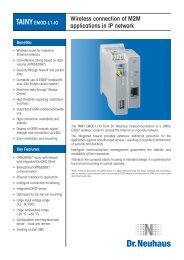
<strong>SATELSET</strong><strong>SATELSET</strong> battery packThe <strong>SATELSET</strong> battery pack makes it possible to use SATELLINE m2 radio modems inmobile applications where an external power supply is not available. Compatible radiomodem types are: 1ASm2, 2ASm2, 2ASxm2 and SATELLINE-2ASxE.The <strong>SATELSET</strong> consists of a battery, an RS-232 adapter and a belt clip all in an integrated,tidy package. Also included is a custom battery charger.1 BatteryThe battery pack has a capacity of 1800 mAh at 9.6V. The eight Ni-MH cells have a shortcircuitprotection by an active self-resetting fuse. An internal temperature probe is used toprevent overheating during the rapid charge cycle. The battery can be recharged approximately500...700 times.top viewThe Batteryfront viewAttachment recessesback viewBelt clipbottom viewRestraining screwBatteryconnector1
<strong>SATELSET</strong>2 ChargerThe charging unit is fully automatic and is capable of recharging the battery pack in 1.5hours. Note that due to special construction the charger must not be used with any otherequipment. On the charger there is a green LED to show the charging status.LED indication• LED blinks rapidly• LED is on continuously• LED blinks slowlyNo battery connectedNormal charging cycleCharging cycle finished3 Adapter plateThe adapter plate ensures the correct electrical and mechanical connection of the batteryand the radio modem. The 9-pin connector at the base of the adapter is a standardRS232 connector for data communication equipment (see attached schematic). Theadapter has a built-in low voltage detection unit, which emits an acoustic warning signalwhen the battery requires recharging.The Adapter PlateInside view<strong>DTR</strong> SwitchThe internal <strong>DTR</strong> switch can be closed when the <strong>SATELSET</strong> is used with communicationsequipment, which does not provide the <strong>DTR</strong> signal line, used to activate the data modem.Please refer to the user guide of your radio data modem for description of the <strong>DTR</strong> signal.2
<strong>SATELSET</strong>The <strong>DTR</strong> switch is by default open. To close the switch, first open the two hexagonalconnector screws at the bottom of the adapter. Then pull out carefully the plastic bottomplate and the 9-pin connector. Please avoid twisting the flat cable that goes from the 9-pinconnector to the circuit board. To close the <strong>DTR</strong> switch, push the red part outwards with asuitable tool. Then repeat the above steps in a reverse order to close the unit.4 AssemblyAssembly1. Attach modem 2. Attach battery 3. Tighten retaining screw, attachantenna and serial cable.Attach belt clip plate to belt.Turn battery pack sideways andinsert belt clip.Slide battery pack down and let go.3
<strong>SATELSET</strong>The modem is attached to the adapter plate using the two screws provided. The batterycan be attached by engaging the two clasps at the top of the adapter plate into the correspondingrecesses at the top of the battery, then pressing the other end of the batteryagainst the adapter plate, and finally firmly tightening the knurled retaining screw.The assembled unit can then be attached to your belt using the belt clip plate.Please refer to the assembly diagram.5 <strong>SATELSET</strong> Technical SpecificationsBatteryCapacityBattery typeSize H x W x DWeightOperating TemperatureChargerOperating VoltageSize H x W x DWeightOperating TemperatureAdapterSize H x W x DWeight1800 mAhNiMH148 x 64 x 22 mm430 g-25 C... 50 C230 Vac / 50/60 Hz76 x 49 x 33 mm160 g-25 C... 50 C150 x 52 x 28 mm140 gAdapter Schematic9-PIN D-CONNECTOR FEMALE15-PIN D-CONNECTOR MALETO TERMINAL EQUIPMENT32786514TDRDRTSCTSDSRSGNDCD<strong>DTR</strong>MULTIFUSE650 mATDRDRTSCTSDSRSGNDCD<strong>DTR</strong>+VbGND119136107211583TO SATELLINE RADIO MODEMINTERNAL <strong>DTR</strong> SWITCH4( outside view )4