2 - Wagner
2 - Wagner
2 - Wagner
- No tags were found...

Create successful ePaper yourself
Turn your PDF publications into a flip-book with our unique Google optimized e-Paper software.
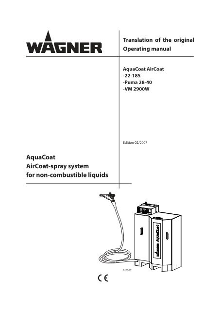
Translation of the originalOperating manualAquaCoat AirCoat-22-18S-Puma 28-40-VM 2900WEdition 02/2007AquaCoatAirCoat-spray systemfor non-combustible liquids
EDITION 02/2007OPERATING MANUALPART NO. DOC0363821AquaCoat GM 2900EACWContents1 ABOUT THESE INSTRUCTIONS 51.1 Languages 51.2 Warnings, notes and symbols in these instructions 52 GENERAL SAFETY INSTRUCTIONS 62.1 Safety instructions for the operator 62.1.1 Electrical equipment 62.1.2 Personnel qualifications 62.1.3 A safe work environment 62.2 Safety instructions for staff 62.2.1 Safe handling of WAGNER spray units 72.2.2 Earth the unit 72.2.3 Paint hoses 72.2.4 Cleaning 82.2.5 Handling hazardous liquids, varnishes and paints 82.2.6 Touching hot surfaces 82.3 Correct use 82.4 Safety-relevant information about discharges 83 PRODUCT LIABILITY AND WARRANTY 93.1 Important notes on product liability 93.2 Warranty 93.3 CE-conformity 103.4 German regulations and guidelines 114 DESCRIPTION 124.1 Fields of application, using in accordance with the instructions 124.1.1 Processible materials 124.2 Delivery scope 124.2.1 Spraypack-Configuration 134.3 Technical data 154.3.1 Control unit VM 2900W 164.3.2 Spray gun GM 2900EACW 174.3.4 Pneumatic piston pump 22-18S PE+TG 184.3.5 Pneumatic piston pump Puma 28-40 PE+TG 184.4 Functional descriptions 194.4.1 Control unit VM 2900W 224.4.2 Design of spraygun GM 2900EACW-F 254.4.3 Design of spraygun GM 2900EACW-R 254.4.4 Operation of the guns 264.4.5 Spraying process 264.4.5.1 AirCoat round jet process 264.4.5.2 AirCoat flat jet process 274.4.5.3 The electrostatic effect 274.4.6 Pneumatic piston pump 22-18S PE+TG 284.4.7 Pneumatic piston pump Puma 28-40 PE+TG 284.4.8 Double diaphragm pump Cobra 40-10 283
EDITION 02/2007OPERATING MANUALPART NO. DOC0363821AquaCoat GM 2900EACWContents5 STARTING UP AND OPERATING 295.1 Installation and connection 295.1.1 Ventilation of the spray booth 295.1.2 Air supply 305.1.3 Fluid (paint) hoses 305.1.4 Earthing 315.1.5 Safety checks 325.1.5.1 Earthing check 325.1.5.2 Inspection of the safety elements 325.2 Preparation of water paint 335.2.1 Viscosity conversion table 335.3 Start-up 345.3.1 General rules for handling the spray gun 345.3.2 Preparation for starting up 355.3.2.1 Spraypack with pneumatic pump 22-18S 355.3.2.2 Spraypack examples with Double diaphragm pump Cobra 40-10 375.4 Works 395.4.1 Start-up for spraying AirCoat 395.4.2 Cleaning of clogged round jet nozzles 405.4.3 Replacing the nozzle insert (EAC round) 415.4.4 Changing from AirCoat round jet nozzle to flat jet nozzle AirCoat 415.4.5 Replacing airCoat flat jet nozzle 425.4.6 Cleaning of AirCoat flat jet nozzles 425.4.7 Control unit VM 2900W - formulas 435.4.8 Control unit VM 2900W - Modification and storage of formulas 436 MAINTENANCE 446.1 Finishing work and cleaning 457 TROUBLE SHOOTING AND SOLUTION 468 REPAIRS 488.1 Replacing the valve seat assy. 498.2 Replacing the valve rod 508.3 Replacing the spray gun including hose set 518.4 Exchange of Material hose and/ or air hose 539 DISPOSAL OF THE PRODUCT 5510 ACCESSORIES 5610.1 AirCoat nozzle inserts round jet 5610.1.1 Nozzle screwed connection complete 5610.2 AirCoat flat jet nozzles Brillant 5710.3 Special tools 5810.4 Miscellaneous 5911 SPARE PARTS 6111.1 How to order spare parts? 6111.2 Spare part list AquaCoat basic unit 6211.3 Spare parts list VM 2900W 6311.4 Spare parts list GM 2900EACW 644
EDITION 02/2007OPERATING MANUALPART NO. DOC0363821AquaCoat GM 2900EACW1 ABOUT THESE INSTRUCTIONS 1.1 LANGUAGES 0363820 03638210363822 03638230363824 03638250363827 0363826The corresponding service instructions are available under the following order number:Language: Part No. Language: Part No.German0353895 English03538961.2 WARNINGS, NOTES AND SYMBOLS IN THESE INSTRUCTIONS 5
EDITION 02/2007OPERATING MANUALPART NO. DOC0363821AquaCoat GM 2900EACW2 GENERAL SAFETY INSTRUCTIONS2.1 SAFETY INSTRUCTIONS FOR THE OPERATOR 2.1.1 ELECTRICAL EQUIPMENT 2.1.2 PERSONNEL QUALIFICATIONS 2.1.3 A SAFE WORK ENVIRONMENT 2.2 SAFETY INSTRUCTIONS FOR STAFF 6
EDITION 02/2007OPERATING MANUALPART NO. DOC0363821AquaCoat GM 2900EACW2.2.1 SAFE HANDLING OF WAGNER SPRAY UNITS 2.2.2 EARTH THE UNIT 2.2.3 PAINT HOSES 7
EDITION 02/2007OPERATING MANUALPART NO. DOC0363821AquaCoat GM 2900EACW2.2.4 CLEANING 2.2.5 HANDLING HAZARDOUS LIQUIDS, VARNISHES AND PAINTS 2.2.6 TOUCHING HOT SURFACES 2.3 CORRECT USE 2.4 SAFETY-RELEVANT INFORMATION ABOUT DISCHARGES 8
EDITION 02/2007PART NO. DOC0363821AquaCoat GM 2900EACWOPERATING MANUAL3 PRODUCT LIABILITY AND WARRANTY3.1 IMPORTANT NOTES ON PRODUCT LIABILITY 3.2 WARRANTY 9
EDITION 02/2007OPERATING MANUALPART NO. DOC0363821AquaCoat GM 2900EACW3.3 CE-CONFORMITYHerewith we declare that the supplied version of0363010 Spraypack AquaCoat AirCoat0363020 Spraypack AquaCoat 22-18S0363021 Spraypack AquaCoat Puma 28-40Complies with the following provisons apllying to it:98/37/EG73/23/EWG89/336/EWG2002/95/EG2002/96/EGApplied standards, in particular:EN 12100-1EN 12100-2EN 1050EN 1953EN 563EN 60204-1EN 50059EN 61000-6-1EN 61000-6-2EN 61000-6-3EN 61000-6-4Applied national technical standards and specifications, in particular:BGI 740BGI 764BGR 500Marking: 036389010
EDITION 02/2007OPERATING MANUALPART NO. DOC0363821AquaCoat GM 2900EACW3.4 GERMAN REGULATIONS AND GUIDELINES 11
EDITION 02/2007OPERATING MANUALPART NO. DOC0363821AquaCoat GM 2900EACW4 DESCRIPTION4.1 FIELDS OF APPLICATION, USING IN ACCORDANCE WITH THE INSTRUCTIONSAquaCoat Spray Packs are equipped ready-for-use with the VM 2900W control unit, a GM2900EACW AirCoat spray gun and matching hose set, a high voltage generator, all safetydevices and spray material supply, and are therefore suitable for AirCoat applications.4.1.1 PROCESSIBLE MATERIALSOnly non-combustible liquid spray materials in accordance with EN 50059 (VDE 0745 part200) with a specific resistance of 1 kΩ. cm to 1 MΩ. cm may be processed with this spraygun.In the event of application problems, contact your WAGNER branch or the paint manufacturer.4.2 DELIVERY SCOPEAquaCoat-AirCoat Spray Packs can be assembled according to requirement and the desiredaccessories with the help of the Spray Pack configuration.All devices are assembled ready-for-use in the factory on the basis of the resulting configurationnumber.The scope of supply of each system includes:Part-No.DescriptionAquaCoat-Spraypack consisting of:- AquaCoat cabinet- Spray gun GM 2900EACW- Control unit VM 2900W- Pump- Accessories0363820 Operating manual Germansee chapter 1 Operating manual in the local languageOperating manual for pump GermanOperating manual for pump in the local languagesee chapter 3.3 CE-Declaration of Conformity AquaCoatThe delivery note shows the exact scope of delivery.12
EDITION 02/2007OPERATING MANUALPART NO. DOC0363821AquaCoat GM 2900EACW4.2.1 SPRAYPACK-CONFIGURATIONTo order the AquaCoat Spray Pack, please use model identification 0363010-ABCDEFGHtogether with the following tables.Table -> A B C D E F G HExamples -> 0363010 - 1 411 1 1 4 2 1 2-> 0363010 - 6 R21 2 1 1 4 2 4Configuration numberPumpTable „A“Nozzle systemTable „B“AgitatorTable „C“Level monitoringTable „D“Hose lengthTable „E“Hose holder / Feed tankTable „F“Container coverTable „G“High-press. filter/ UnderframeTable „H“13
EDITION 02/2007OPERATING MANUALPART NO. DOC0363821AquaCoat GM 2900EACWTable “A” PumpNumber Type1 22-18S2 Wildcat 10-703 Wildcat 18-404 Puma 15-705 Puma 28-406 Cobra 40-107 Cobra 40-10 of frameTable “C” AgitatorNumber Type1 no agitator2 AgitatorTable “B” Nozzle system (examples) (*)Number Description411 Flat jet with nozzle 11/40413 Flat jet with nozzle 13/40513 Flat jet with nozzle 13/50615 Flat jet with nozzle 15/60R12 Round jet with nozzle R 12R13 Round jet with nozzle R 13R14 Round jet with nozzle R 14Table “D” Level monitoringNumber Designation1 no2 yesTable “E”NumberHose lengthTypeTable “F” Hose holder/ Feed tankNumber Description1 7.5 m; 24.6 ft2 10 m; 32.8 ft3 15 m; 49.2 ft4 20 m; 65.6 ft1 no2 Hose holder3 Feed tank4 Hose holder + Feed tankTable “G”NumberBarrel coverTypeTable “H” High-pressure filter/ UnderframeNumber Description1 no2 Ø 350 mm; Ø 13.8 inch1 Filter discharge combination2 High-pressure filterFilter discharge combination +3Underframe4 High-pressure filter + Underframe5 Underframe6 no(*) Note to table „B“: The complete <strong>Wagner</strong> nozzle range can be found in the accessories in Chapter 10. Forflat-jet nozzles, the last 3 digits of the order number are used, and for round-jet nozzles the identificationdigits with preceding „R“ are used.14
EDITION 02/2007OPERATING MANUALPART NO. DOC0363821AquaCoat GM 2900EACW4.3 TECHNICAL DATAWeight70 kg; 154 lb(without Paint reservoir and Pump)Working temperatur range5-40°C; 41-104°FMaximum material temperature 60°C; 140°FSound pressure levelWhen the cabinet is open:Dependent on the installed pump; data can be found in theenclosed operating instructions.When the cabinet is closed:The values are 10 - 12 dB(A) lower.Dimensionsmm inchA = 1390 54.72B = 616 24.25C = 1000 39.3715
EDITION 02/2007OPERATING MANUALPART NO. DOC0363821AquaCoat GM 2900EACW4.3.1 CONTROL UNIT VM 2900WDescriptionDataInput voltage85-264 VAC 47-440 HzInput powermax. 25 WOutput voltagemax. 22 VppOutput currentmax. 1.2 AHigh voltage limiter70 kV DCSpraying current limit120 µA DCPolarityfor positive and negative high voltage generatorWeight (without cable) 6.2 kg 13.67 lbWorking temperature range 5-40°C 41-104°FDimenionsmm inchA = 136 5.35B = 370 14.57C = 220 8.66D = 252 9.9216
EDITION 02/2007PART NO. DOC0363821AquaCoat GM 2900EACWOPERATING MANUAL4.3.2 SPRAY GUN GM 2900EACWDescriptionDataAir pressure max. 0.8 MPa 8 bar 116 psiMaterial pressure max. 25 MPa 250 bar 3626 psiPaint connectionM16x1.5Air connection R 1/4“Hose set lengths 7.5 m 24.6 ft10 m 32.8 ft15 m 49.2 ft20 m 65.6 ftWeight (without cables) 0.8 kg 1.76 lbWorking temperature range 5-40°C 41-104°FMax. material temperature 60°C 140°FQuantity of fluidaccording to nozzle sizes(See nozzle list on accessories)Sound power at 0.2 MPa; 2 bar; 29 psi air pressure65 - 79 dB(A)(depending on nozzle used)DimensionsmminchA = 347 13.66B = 255 10.04C = 40 1.5817
EDITION 02/2007OPERATING MANUALPART NO. DOC0363821AquaCoat GM 2900EACW4.3.4 PNEUMATIC PISTON PUMP 22-18S PE+TGSee separate operating instructions4.3.5 PNEUMATIC PISTON PUMP PUMA 28-40 PE+TGSee separate operating instructions18
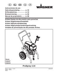
EDITION 02/2007OPERATING MANUALPART NO. DOC0363821AquaCoat GM 2900EACW4.4 FUNCTIONAL DESCRIPTIONSPos Description1 Cabinet AquaCoat assy.2 Front panel with 2 handles3 Control unit VM 2900W4 Spray gun GM 2900EACW-F or GM 2900EACW-R5 Hose set EACW6 Material hose (Filter-relief combination for spray gun)7 Cascade AquaCoat8 Air inlet assembly with ball valve9 Inlet for mains cable10 Earthing cable19
EDITION 02/2007OPERATING MANUALPART NO. DOC0363821AquaCoat GM 2900EACWPos Description11 Material pressure generator such as pneumatic pump or double membranepump12 Suction system assembly13 Paint container14 Earthing switch (Cylinder AquaCoat)15 Earthing band16 Filter-relief combination17 Door switch19 Resistance AquaCoat20 Air hose (Material pressure generator)22 High voltage cable (2 pieces)23 Base frame assy. (available, however, as additional extra)24 Hose holder assy. (available, however, as additional extra)26 Return hoseThe AquaCoat spray system is designed for processing non-combustible liquids in accordancewith the AirCoat spraying method.The spray product is regulated via the trigger guard on the spray gun (4) and by the VM2900W control unit (3), drawn in with a material pressure generator (11) via a suction system(12), electrostatically charged in the sealed off inner chamber of the AquaCoat cabinet(1) and sprayed in the nozzle of the spray gun with the help of AirCoat airThe material pressure generator and spray gun are connected by the shielded materialhose.The following functions are provided for system safety:The earthing switch (14), the door switch (17), the earthing strip (15) and the integratedAquaCoat resistor (19).Note:Only mount or remove the front panel(2) when the control unit (3) is switchedoff. 1 second after the control unit (3) hasbeen switched off, the system is earthedand the door lock opened. 20
AquaCoat GM 2900EACWEDITION 02/2007OPERATING MANUALPART NO. DOC0363821Electrical block diagram AquaCoat 21
EDITION 02/2007OPERATING MANUALPART NO. DOC0363821AquaCoat GM 2900EACW4.4.1 CONTROL UNIT VM 2900WThe assembled spray system can be operated and regulated with the VM 2900W controlunit.Front of the control unit1 2 53 46 78 10911 12 13161415171819 20 21 22 23 24 25B_018801 High voltage display (Luminous display green)Readings between 0 to 80 kV.(Resolution of 0 - 20 kV ->5 kV and 20 - 80 kV -> 10 kV)- Single LED display: Indicates the required high-voltage value in kV.(with the spray gun switched off )- Bar graph LED display: Indicates the actual high-voltage value in kV.(with the spray gun switched on)2 Spraying current display (Luminous display green)Readings between 0 to 120 µA(Resolution of 0 to 80 µA = 10 µA; and 80 - 120 µA = 20 µA)- Single LED display: Current limiter activation point(with the spray gun switched off ).- Bar graph LED display: Indicates the actual corona current value(with the spray gun switched on).3 Push-button: formula R14 Push-button: formula R25 Push-button: formula R36 Formula LED display R1:Lights up green when formula R1 is selected.7 Formula LED display R2:Lights up green when formula R2 is selected.8 Formula LED display R3:Lights up green when formula R3 is selected.9 Fault LED display (Illuminated display, red)Lights up in the event of a fault in the AquaCoat -> see also description in chap. 7.22
EDITION 02/2007OPERATING MANUALPART NO. DOC0363821AquaCoat GM 2900EACW10 High voltage LED display (Illuminated display, green)Lights up when the high voltage on the gun is switched on.11 Pressure gauge- Atomization air pressure display for the spray gun- Readings between 0-1 MPa; 0-10 bar; 0-145 psi.12 Pressure gauge- No function13 Pressure gauge- Air pressure display, when a 22-18S pump is in use- Readings between 0-1 MPa; 0-10 bar; 0-145 psi.14 Push-button: high-voltage „higher“15 Push-button: high-voltage „lower“16 Push-button: Spraying current limit more“17 Push-button: Spraying current limit less“18 Push-button: Formula - Manual setting of parameters19 Formula LED display Manual setting:Lights up green when manual formula setting is selected.20 Push-button: Stand ByTo switch to stand-by mode.High voltage cannot be activated in this mode.Press the button again for normal operation.21 Stand-By LED displayLights up when stand-by mode is activated.22 RegulatorAdjust pressure for the atomization air.Adjustment between 0-1.0 MPa; 0-10 bar; 0-145 psi.23 Regulator- No function24 RegulatorAir pressure for pump pressure when using a 22-18S pump.Adjustment between 0-1.0 MPa; 0-10 bar; 0-145 psi.25 Mains switch (Power)0 = Control unit switched off1 = Control unit switched on23
EDITION 02/2007OPERATING MANUALPART NO. DOC0363821AquaCoat GM 2900EACWRear of the control unit26272829303132343335B_018903626 Connection socketConnection for mains cable with securing clip27 Connection Pump airHose connection ø 10 mm; ø 0.39 inch.28 Connection Material pressure regulatorHose connection ø 8 mm; ø 0.32 inch.29 Connection Atomizing airHose connection ø 8 mm; ø 0.32 inch.30 Connection socketConnection for gun cable31 Connection socketConnection for high voltage generator32 Self-locking nut EarthingConnection for the earthing cable (system earth)33 Primary fuse1.0 ampere slow-acting34 Compressed air connectionHose connection ø 10 mm; ø 0.39 inch.35 Connection Earthing switch, airHose connection ø 6 mm; ø 0.24 inch.36 CoverService connection24
EDITION 02/2007OPERATING MANUALPART NO. DOC0363821AquaCoat GM 2900EACW4.4.2 DESIGN OF SPRAYGUN GM 2900EACW-FA Air capB Union nut EACW-FC Gun barrelD Spray gun bodyE Suspension hookF Fan air regulatorG Clamping nutH HV flip switch(integrated into trigger)I HandleJ Trigger guardK Air hoseL Gun cableM Material hoseN Protective tubeO Nozzle ACF-Brillant ../.(see chap. 9.1)AOBCDNEFGHIJKLB_01954M4.4.3 DESIGN OF SPRAYGUN GM 2900EACW-RA Nozzle body 2900EACWB Union nut EACW-RC Gun barrelD Spray gun bodyE Suspension hookF Fan air regulator (for flat jetprocess)G Clamping nutH HV flip switch(integrated into trigger)I HandleJ Trigger guardK Air hoseL Gun cableM Material hoseN Protective tubeO Nozzle insert R.. (see chap. 9.2)25
EDITION 02/2007OPERATING MANUALPART NO. DOC0363821AquaCoat GM 2900EACW4.4.4 OPERATION OF THE GUNSThe trigger can be used to activate, one after the other,the various functions of the spray gun.AW = Max way of triggerLM = AirCoat air openLE = AirCoat air open and electrostatics activatedLO = AirCoat air open and elektrostatics activated and materialvalve open.➞➞➞An increase in the tension needed to pull the triggerback will be felt at the position where the materialvalve opens.In order to overcome Faraday cages in corners, thehigh voltage can be switched off by flipping the HVswitch (F) down.When using a flat jet, the spray jet width is adjustedusing the fan air regulator (F).4.4.5 SPRAYING PROCESS4.4.5.1 AIRCOAT ROUND JET PROCESSWith the AirCoat-spraying process the spray material is atomized at a pressure of approx.3-15 MPa; 30-150 bar; 435-2176 psi. A soft, flat spray is achieved with help of the AirCoatair, which has a pressure of 0-0.25 MPa; 0-2.5 bar; 0-36 psi. The spray jet can be adjusted byturning the union nut..AirCoat AirMaterialAirCoat AirUnion nutMulti-channelswirl nozzleAdvantagesHigh painting capacityLow fogging tendencyGood finish• High- viscosity paints can easily be appliedSpray jet26
EDITION 02/2007OPERATING MANUALPART NO. DOC0363821AquaCoat GM 2900EACW4.4.5.2 AIRCOAT FLAT JET PROCESSIn the Brillant AirCoat process, high pressure of 3-15 MPa; 30-150 bar; 435-2176 psi is usedto atomize the material. The AirCoat air at 0-0.25 MPa; 0-2.5 bar; 0-36 psi produces a soft jet,which largely eliminates the problem of overlapping boundaries. There´s a possibility toreduce the jet by form air.Form airAir capSpray jet adjustableAtomizing airAdvantagesHigh painting capacityLow fogging tendencyGood finishHigh- viscosity paints can easily be appliedHigh endurance of Brillant- jet-tipsUp to 20% less air consumption• Change in width the jet4.4.5.3 THE ELECTROSTATIC EFFECTAfter being electrically charged in the system and atomized by the spray gun, the paintparticles are now transported by kinetic and electrostatic energy to the earthed workpieceand adhere to the sprayed object, finely distributed over the entire surface.Paint particlesGroundedobjectAdvantagesVery efficient sprayingLittle oversprayCoating of entire circumferences due to an electrostatic field• Less working time27
EDITION 02/2007OPERATING MANUALPART NO. DOC0363821AquaCoat GM 2900EACW4.4.6 PNEUMATIC PISTON PUMP 22-18S PE+TGFunctional descriptions see separate operating instructions4.4.7 PNEUMATIC PISTON PUMP PUMA 28-40 PE+TGFunctional descriptions see separate operating instructions4.4.8 DOUBLE DIAPHRAGM PUMP COBRA 40-10Functional descriptions see separate operating instructions28
EDITION 02/2007OPERATING MANUALPART NO. DOC0363821AquaCoat GM 2900EACW5 STARTING UP AND OPERATING5.1 INSTALLATION AND CONNECTION Check the individual components of the AquaCoat spray system against the delivery note.Familiarize yourself with the mode of functioning of the individual components of theAquacoat spray system, reading the enclosed operating instructions thoroughly. Note thespecial requirements of the electrostatic air spray procedure.5.1.1 VENTILATION OF THE SPRAY BOOTH 29
EDITION 02/2007OPERATING MANUALPART NO. DOC0363821AquaCoat GM 2900EACW5.1.2 AIR SUPPLYYou must ensure that only dry, clean atomizing air is used in the spray gun. Dirt and moisturein the atomising air reduce the spraying quality and the appearance of the finishedpiece.5.1.3 FLUID (PAINT) HOSES 30
EDITION 02/2007OPERATING MANUALPART NO. DOC0363821AquaCoat GM 2900EACW5.1.4 EARTHINGPerfect earthing of all system components (workpieces, conveyor, paint supply system,control unit, spraying cabin or spraying stand, se illustration) is a prerequisite for optimumcoating efficiency and safety. The imperfect earthing of a workpiece will result in:● Very poor wrap-around● Uneven coating thickness● Backspraying to the spray gun, i.e. contamination.The prerequisites for perfect earthing and coating are:● Clean workpiece suspension● Earthing of spraying cabin, conveyor system and suspension on the building side inaccordance with the operating instruction or the manufacturer‘s information● Earthing of all conductive parts within the working area● The earthing resistance of the workpiece may not exceed 1 MΩ (Mega Ohm).● Connect the AquaCoat-cabinet to the system earth.Earthing schema (example)ConveyorMinimum cable cross-sectionObjectAquaCoat-cabinet 4 mm 2 ; AWG 12Conveyor 16 mm²; AWG 6Spray booth 16 mm²; AWG 6Spraying stand 16 mm²; AWG 6 Spraying standSystem earthAnti-static floorSystem earth31
EDITION 02/2007OPERATING MANUALPART NO. DOC0363821AquaCoat GM 2900EACW5.1.5 SAFETY CHECKS5.1.5.1 EARTHING CHECKEvery days:Before starting work, carry out a visual check to ensure that the earthing connection ispresent in the AquaCoat cabinet and in all relevant components.5.1.5.2 INSPECTION OF THE SAFETY ELEMENTSEvery days:- General visual inspection:Earthing band, all cables and connections for damage or loose contacts examine.Monthly:- Door switch test:Remove the front panel.Turn on control unit.Actuate the trigger guard on the spray gun.The high voltage must remain switched off.- Earthing cylinder test:Insert front panel.Turn on control unit.Acoustically ascertain switch movement.Check that the front panel is locked.Switch off the control.Acoustically ascertain switch movement.32
EDITION 02/2007OPERATING MANUALPART NO. DOC0363821AquaCoat GM 2900EACW5.2 PREPARATION OF WATER PAINTThe viscosity of the paints is of great importance. The best results are obtained with paintsbetween 25 and 40 DIN-sec (measured in immersion flow cup DIN 4 mm; 0.16 inch).Processing of up to 60 DIN-s is generally possible without problem, if high coating thicknessesare required.In the case of application problems contact the paint producer.5.2.1 VISCOSITY CONVERSION TABLE 33
EDITION 02/2007OPERATING MANUALPART NO. DOC0363821AquaCoat GM 2900EACW5.3 START-UP5.3.1 GENERAL RULES FOR HANDLING THE SPRAY GUN➞ Observe general safety instructions in chapter 2. Note:In order to avoid electrical discharges,a distance of 100 mm; 4 inches mustbe maintained from the workpieceand other earthed objects during thespray process.Danger zone 34
EDITION 02/2007OPERATING MANUALPART NO. DOC0363821AquaCoat GM 2900EACW5.3.2 PREPARATION FOR STARTING UP 5.3.2.1 SPRAYPACK WITH PNEUMATIC PUMP 22-18S35
EDITION 02/2007OPERATING MANUALPART NO. DOC0363821AquaCoat GM 2900EACWNote:The 22-18S pump must be mounted inthe front hole of the mounting plate, asshown in the illustration.B_01983The following points must be noted:1. Place container (13) with suitable detergent into the AquaCoat cabinet and immersethe suction system, so that the system can be checked for leaks.2. Connect the earth.3. Connect the AquaCoat system to the compressed air source (8). Set maximum pressure0.8 MPa; 8 bar; 116 psi on the material pressure control unit. Maintain the pressure for5 minutes and check all connecting parts for leaks.4. When the tightness of the system has been ascertained, the spray gun can be unlockedand the system flushed through.5. Depressurize the system and secure the spray gun (4).6. Remove the detergent.7. Fill the material container (13) with paint, place in the cabinet and immerse the suctionsystem (12).8. Clamp HV cable (22) to the metal material container (13) or, in the case of a plasticcontainer, to the metal part of the suction system (12).9. Connect the AquaCoat system to the electric socket with the electric cable (9).10. Insert front panel (2). Switch on mains switch on the VM 2900W. 11. The system is ready for use.36
EDITION 02/2007OPERATING MANUALPART NO. DOC0363821AquaCoat GM 2900EACW5.3.2.2 SPRAYPACK EXAMPLES WITH DOUBLE DIAPHRAGM PUMP COBRA 40-10Cobra 40-10 vertical mounted with suction systemThe following points must be noted:1. Place container (13) with suitable detergent into the AquaCoat cabinet and immersethe suction system, so that the system can be checked for leaks.2. Connect the earth.3. Connect the AquaCoat system to the compressed air source (8). Set maximum pressure0.6 MPa; 6 bar; 87 psi on the regulator unit Cobra 10-40. Maintain the pressure for 5minutes and check all connecting parts for leaks.4. When the tightness of the system has been ascertained, the spray gun can be unlockedand the system flushed through.5. Depressurize the system and secure the spray gun (4).6. Remove the detergent.7. Fill the material container (13) with paint, place in the cabinet and immerse the suctionsystem (12).8. Clamp HV cable (22) to the metal material container (13) or, in the case of a plasticcontainer, to the metal part of the suction system (12).37
EDITION 02/2007OPERATING MANUALPART NO. DOC0363821AquaCoat GM 2900EACW9. Connect the AquaCoat system to the electric socket with the electric cable (9).10. Insert front panel (2). Switch on mains switch on the VM 2900W. 11. The system is ready for use.Cobra 40-10 mounted on frame with upper hopper set38
EDITION 02/2007OPERATING MANUALPART NO. DOC0363821AquaCoat GM 2900EACW5.4 WORKS5.4.1 START-UP FOR SPRAYING AIRCOAT 1. Turn on the control unit VM 2900W. Set main switch (1) to position 1. During thestart-up phase, the device automatically performs an internal function test and thenautomatically switches to manual formula setting (7).2. Set the desired formula.3. Set material pressure on the regulator for pump (8) at approx. 8 MPa; 80 bar; 1160 psi.Note:In the case of material pressure generators with attached control unit, use the regulatoron the device.4. Release the spray gun with the clamping nut (turn to the left, viewed in the sprayingdirection)5. Spray on a test object (press the trigger), the high voltage is switched on and bothdisplays (6) and (5) change from point to bar display, i.e. the actual value of the highvoltage (6) and the actual value of the spray current (5) are displayed.6. The high voltage can be switched on and off with the pushbutton (4).7. Now open AirCoat air (3), approx. 1-2.5 bar; 0.01-0.25 MPa; 14.5-36 psi, and adjust forthe optimal atomization.When using a round jet:8. By turning the tip nut, the atomizing air jet can additionally be adjusted.NoteDo not turn the nozzle nut until it is flush with the nozzle body. Always allow playbetween the nozzle nut and body for the atomizing air.39
EDITION 02/2007OPERATING MANUALPART NO. DOC0363821AquaCoat GM 2900EACWWhen using a flat jet:8. Change the spray jet width by turning the shaping air control on the spray gun or byselecting the appropriate nozzle.View ASeen from thespraying directionWide spray angle =minimale shaping air adjustmentNarrow spray angle =maximale shaping air adjustment5.4.2 CLEANING OF CLOGGED ROUND JET NOZZLES1. Use the nozzle spanner (2) to undo the nozzle insert (1) by half a turn.2. Remove nozzle spanner and switch on for a short amount of time.3. After cleaning the nozzle retighten.40
EDITION 02/2007OPERATING MANUALPART NO. DOC0363821AquaCoat GM 2900EACW5.4.3 REPLACING THE NOZZLE INSERT (EAC ROUND)1. Remove nozzle insert (2) with nozzlespanner (1).2. Fit the new insert.5.4.4 CHANGING FROM AIRCOAT ROUND JET NOZZLE TO FLAT JET NOZZLE AIRCOAT1. Throughly flush spray gun withcleaning solvent2. Relieve the pressure of gun and device.3. Secure the gun. Turn tension capclockwise until stop. (viewed from backof gun)4. Unscrew connection nut EAC-R (1).5. Loosen sealing nipple (3) and nozzlebody (2) from end piece (4) withuniversal spanner.6. Screw sealing ring including O-ring (9)onto end piece (4) and tighten lightly.7. Insert Brillant flat-jet nozzle (8) on colorchannel into the end piece (4).8. Place the air cap (7) on the Brillant flatjetnozzle (8).Attention: fit teeth of the air capinto the grooves in the Brillant flat jetnozzle.9. Mount connection nut EAC-F (5) overthe air cap (7) onto the end piece (4).10. Set the desired jet level with the air capclamps (6) and tighten connection nutEAC-F (5) as far as the stop by handUniversal spanner 41
EDITION 02/2007OPERATING MANUALPART NO. DOC0363821AquaCoat GM 2900EACW5.4.5 REPLACING AIRCOAT FLAT JET NOZZLE1. Switch off control unit.2. Relieve spray gun and unit pressure!3. Secure gun (Turn locking nut to theright)4. Unsrew union nut EAC-F (5) andremove air cap (7).5. Remove AirCoat nozzle (8) and brushcleaning solvent until all traces of paintare dissolved. 6. Assembly: Fit AirCoat nozzle (8) on the paint channel in the attachment (4).7. Screw air cap (7) on the flat jet nozzle (8);Attention: fit teeth of the air cap into the grooves in the flat jet nozzle.8. Screw union nut (5) with air cap (7) on the attachment (4).9. Adjust desired jet level by means of air cap horns (6) and tighten cap ring (5) by hand.5.4.6 CLEANING OF AIRCOAT FLAT JET NOZZLES For disassembly and assembly of AirCoat nozzles see chapter 5.4.5. The AirCoat nozzle (7)can be placed into a cleaning solvent which has been recommended by the paint manufacturer.42
EDITION 02/2007OPERATING MANUALPART NO. DOC0363821AquaCoat GM 2900EACW5.4.7 CONTROL UNIT VM 2900W - FORMULASThe VM 2900W control unit has 4 preset formulas.These formulas are set in the factory as follows:R1: Profiled parts (11) 70 kV 120 µAR2: Re-coating (10) 60 kV 100 µAR3: Surface parts (9) 40 kV 60 µAManual setting: (8) 60 kV 80 µA5.4.8 CONTROL UNIT VM 2900W - MODIFICATION AND STORAGE OF FORMULAS1. Increase or reduce the high voltage with key 3 or 4.2. Set the current limiter higher or lower with key 5 or 63. The device has switched to manual formula setting 8.4. Keep the formula key pressed down until the middle six diodes light up on both bardisplays 1 and 2.5. The new values are now stored in this formula and are preserved even when the controlunit is switched off.43
EDITION 02/2007OPERATING MANUALPART NO. DOC0363821AquaCoat GM 2900EACW6 MAINTENANCE➞ Observe general safety instructions in chapter 2.The AquaCoat-system must be cleaned every day. Use only the cleaning solvent recommendedby the material manufacturer. 44
EDITION 02/2007OPERATING MANUALPART NO. DOC0363821AquaCoat GM 2900EACW6.1 FINISHING WORK AND CLEANING1. Switch off the control unit and remove the front panel.2. Ensure that the material pressure is relieved and shut off the air supply to the gun.3. Remove round-jet or flat-jet nozzle and clean separately.4. Connect the system to the detergent supply.5. Actuate the trigger guard and flush the gun through thoroughly.6. Relieve the pressure of gun and device and remove the detergent supply.7. Switch on the air supply to the gun and blow through the air channels.8. Switch off the air supply to the gun.9. Relieve unit pressure and spraygun.10. Clean the body of the gun and other AquaCoat components with a washing solutionrecommended by the paint manufacturer and dry with a cloth or an air-jet gun. XThe gun barrel (X) may only be detatchedby the WAGNER Service Station.B_0196545
EDITION 02/2007OPERATING MANUALPART NO. DOC0363821AquaCoat GM 2900EACW7 TROUBLE SHOOTING AND SOLUTIONFault Cause SolutionInsufficient material• Nozzle too small• Select larger nozzle (see nozzle table)discharge• Material pressure to low • Increase material pressure• Material viscosity to high • Thin material in accordance with themanufacturer ‚s instructions• Filter in material supply • Clean or replace filterclogged• Nozzle is clogged• Clean or replace nozzle• Tension nut is screwed in to • Turn tension nut anticlockwisefarPoor spray pattern• Wrongly adjusted atomizing • Readjust atomizing airair• Nozzle to large• Select smaller tip (see nozzle table• Material viscosity to high • Thin material in accordance with themanufacturer‘s instructions• Material pressure to low • Increase material pressure at pump• Damaged nozzle• Replace new nozzleAir leaks• Air valve seal on valve tappetleaking• Have seal replaced by WAGNER ServiceDepartment• Seal on air regulating pinleaking• Tappet seal leaking• Have seal replaced by WAGNER ServiceDepartmente• Have tappet seal replaced by WAGNERService DepartmentPoor wrap-around • Poor earthing at object • Check earthing of object or hanger withohmmeter.• Paint resistance to high / tolow• Spraying pressure to highSpray-back • Object not earthed • Check earthing• Distance between spray gunand object to large.• High voltage set wrongly (tohigh)• Check resistance of paint in accordancewith para. 4.1.1• Readjust pressure• Reduce distance between spray gun andobject• Adapt high voltage to material46
EDITION 02/2007OPERATING MANUALPART NO. DOC0363821AquaCoat GM 2900EACWFault Cause SolutionNo wrap-around • No high voltage • Check function of control unit inaccordance with its manual• Switch on HV• Seal in end piece defective • Repair by <strong>Wagner</strong> Service Center• Air-passages damp• Cleaning air-passages and dryingLeaking material at the nozzle • Valve seat (10) worn • Replace part and check for leaks withair in water (see chap. 8.1) If still leaking,change valve rod tip.VM 2900W: No green LEDdisplays (2) and (3) visibleVM 2900W: „Fault“ display (1)lights up together with LED1VM 2900W: „Fault“ display (1)lights up together with LED2VM 2900W: „Fault“ display (1)lights up together with LED3VM 2900W: „Fault“ display (1)lights up together with LED5• Seal in front or seal behindover-tightened• Mains not switched on• Stand-by mode• Fuse defective• Internal error• Calibration value lost• Cascade not connected ordefective• Earth monitoring• Loosen the sealing screw at the backuntil the valve rod closesIf still leaking -> <strong>Wagner</strong>-Service.• Turn on mains power• Deactivate stand-by mode• Replace fuse• HV-Modul defective -> <strong>Wagner</strong> Service.• HV-Modul defective -> <strong>Wagner</strong> Service.• Connect or replace cascade• Check spray gun earth 47
EDITION 02/2007OPERATING MANUALPART NO. DOC0363821AquaCoat GM 2900EACW8 REPAIRS 48
EDITION 02/2007OPERATING MANUALPART NO. DOC0363821AquaCoat GM 2900EACW8.1 REPLACING THE VALVE SEAT ASSY.Note:This repair must be carried out with the material hose mounted1. Remove nozzle according to chapter 5.4.3 or 5.4.4.2. With the trigger guard actuated (prevents damage to the valve rod sealing surfaces)loosen and unscrew the complete valve seat (10) with the air nozzle key (9). If necessary,remove sealing nipple (11).3. Assemble in reverse order. 49
EDITION 02/2007OPERATING MANUALPART NO. DOC0363821AquaCoat GM 2900EACW8.2 REPLACING THE VALVE RODDo not damage thesealing surface 1. Pull trigger (4) and unscrew locking nut (5); remove compression spring (6).5. Loosen screw (2) and remove trigger guard (4) with shaft sleeve (3).6. Unscrew sealing screw (1.1) from sealing sleeve (7).7. Carefully pull out complete valve rod (1) using surface (1.2) and replace. 8. Replace in reverse order (Do not forget to screw the sealing screw (1.1) into the sealingsleeve (7)). Place the locking nut (5) with pressure spring (6) in position and tightenwith the trigger (4) open until a considerable resistance is noticeable50
EDITION 02/2007OPERATING MANUALPART NO. DOC0363821AquaCoat GM 2900EACW8.3 REPLACING THE SPRAY GUN INCLUDING HOSE SET1632345B_01968Dissassembly of gun (1)1. Loosen the connection nut (6) on the bared part of the material hose (3) with a universalspanner.2. Loosen knurled nut (2).3. Loosen the connection nut (4) of the air hose at the AquaCoat cabinet.4. Loosen the locking screw on the gun cable (5) and remove connector.5. Carefully remove the gun (1) together with the hose set.51
EDITION 02/2007OPERATING MANUALPART NO. DOC0363821AquaCoat GM 2900EACW4 preassembled guns are available, with different hose set lengths:AirCoat flat jet-guns:Part Number Description0363960 Spray gun GM 2900EACW-F with the hose set 7.5 m; 24.6 ft0363961 Spray gun GM 2900EACW-F with the hose set 10 m; 32.81 ft0363962 Spray gun GM 2900EACW-F with the hose set 15m; 49.2 ft0363963 Spray gun GM 2900EACW-F with the hose set 20m; 65.6 ftAirCoat round jet-gunsPart Number Description0363964 Spray gun GM 2900EACW-R with the hose set 7.5 m; 24.6 ft0363965 Spray gun GM 2900EACW-R with the hose set 10 m; 32.81 ft0363966 Spray gun GM 2900EACW-R with the hose set 15m; 49.2 ft0363967 Spray gun GM 2900EACW-R with the hose set 20m; 65.6 ftAssembly gun (1)1. Secure the spray gun. Turn tension cap clockwise until stop. (viewed from back ofgun).2. Connect gun cable (5) to AquaCoat cabinet and secure with screw.3. Screw air hose for the spray gun (4) to the AquaCoat cabinet.4. Push bared part of material hose approx. 1.15 m; 3.77 ft through the opening as far asthe mounting plate.5. Fix mounting plate (3) to earthing screw with knurled nut (2).6. Screw bared end of material hose (3) with connection nut (6) to relief combination orto pressure generator.52
EDITION 02/2007OPERATING MANUALPART NO. DOC0363821AquaCoat GM 2900EACW8.4 EXCHANGE OF MATERIAL HOSE AND/ OR AIR HOSE1. Isolate spray gun and hose set from the AquaCoat cabinet in accordance with chapter8.5.2. Loosen 2 screws (8), remove cable ties and push protective tube (7) back.3. Loosen material connection (9) with universal spanner and remove material hose (3)from the attachment. Make sure that the sealing nipple (14) is also removed from theend piece.4. Unscrew connection nut (10) from the air hose (4).5. Support the clamping sleeve (13) with the universal spanner and unscrew the doublenipple (11).7. Remove the cable lug (12).8. Carefully remove the air hose (4) backwards from the protective tube (7).9. Carefully remove the completely assembled material hose (3) backwards from theprotective tube (7).10. Assemble in reverse order.4 preassembled material hoses and 4 preassembled air hoses are available in the correspondinghose set lengths:Hose setLengthMaterial hose AC assy.Part No.Air hose assyPart No..7.5 m; 24.6 ft 0363968 035321210 m; 32.81 ft 0363969 035321315m; 49.2 ft 0363970 035321420m; 65.6 ft 0363971 035321553
EDITION 02/2007OPERATING MANUALPART NO. DOC0363821AquaCoat GM 2900EACWAssembly instructions:Mounting materials.Loctite 243Double nipple (11): Threaded joint with clamping sleeve (13)121381110Loctite 243149347B_0197054
EDITION 02/2007OPERATING MANUALPART NO. DOC0363821AquaCoat GM 2900EACW9 DISPOSAL OF THE PRODUCT 55
EDITION 02/2007OPERATING MANUALPART NO. DOC0363821AquaCoat GM 2900EACW10 ACCESSORIES10.1 AIRCOAT NOZZLE INSERTS ROUND JETThe round jet tips are especially suited to spray pipes, profiles andcomplex workpieces.. * = Standard nozzle1.) Volume flow in ml/min; cc/min water at 10 MPa; 100 bar; 1450 psi.2.) Jet width in mm; inch at a distance of 30 cm; 11.8 inch from theobject and at a pressure of 10 MPa; 100 bar; 1450 psi.10.1.1 NOZZLE SCREWED CONNECTION COMPLETEPart No. Description0132922 Nozzle screwed connection complete56
EDITION 02/2007OPERATING MANUALPART NO. DOC0363821AquaCoat GM 2900EACW10.2 AIRCOAT FLAT JET NOZZLES BRILLANT 57
EDITION 02/2007OPERATING MANUALPART NO. DOC0363821AquaCoat GM 2900EACW10.3 SPECIAL TOOLSPart No. Description0128901 Nozzle spanner (for replace round jet nozzles )0353210 Air nozzle spanner 2800 EA (for replace des valve seat)0179901 Universal spanner58
EDITION 02/2007OPERATING MANUALPART NO. DOC0363821AquaCoat GM 2900EACW10.4 MISCELLANEOUSPart No. Description9992511 Loctite 243 50ml; 50 cc(for air connection -> assembly)9994682 Glove against ink mist precipitation0259005 H.V. tester HV 2000999080 Wet film thickness gauge0050342 Viscosity cup DIN40353050 Hose holder assy.0353051 Base frame assy.0353052 Feed tank59
EDITION 02/2007OPERATING MANUALPART NO. DOC0363821AquaCoat GM 2900EACW60
EDITION 02/2007OPERATING MANUALPART NO. DOC0363821AquaCoat GM 2900EACW11 SPARE PARTS11.1 HOW TO ORDER SPARE PARTS? 61
EDITION 02/2007OPERATING MANUALPART NO. DOC0363821AquaCoat GM 2900EACW11.2 SPARE PART LIST AQUACOAT BASIC UNITSpare part list AquaCoat basic unitPos K Qty Part No Description1 1 0353862 Control unit VM 2900W2 1 0353867 Front plate assy.Note: For repairs, please use service instructions article number 0353895. 62
EDITION 02/2007OPERATING MANUALPART NO. DOC0363821AquaCoat GM 2900EACW11.3 SPARE PARTS LIST VM 2900W Spare parts list VM 2900WPos K Qty Part No. Description1 1 9910204 Hexagon nut with clamp2 2 9920118 Washer3 1 9922109 Spring washer4 ◆ 1 9951117 Delay-action fuses 1.0 A◆ = Wearing partNote: For repairs, please use service instructions article number 0353895.63
EDITION 02/2007OPERATING MANUALPART NO. DOC0363821AquaCoat GM 2900EACW11.4 SPARE PARTS LIST GM 2900EACWB_019852364
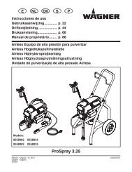
EDITION 02/2007OPERATING MANUALPART NO. DOC0363821AquaCoat GM 2900EACWSpare parts list GM 2900EACWPos K Qty Part No. Description1 1 0363407 Union nut EAC-R2 ◆ 1 0363974 Nozzle body 2900EACW3 ◆ 1 0128327 Sealing nipple4 1 0179396 Shaft collar5 1 9900808 Screw, Flat Head M3x8 mm; 0.31 inch long6 1 9994248 Pressure spring7 1 0179784 Clamping nut assy.8 1 0363418 Clamping ring9 ◆ 1 0363973 Valve seat assy.10 ◆ 1 0363411 Sealing nipple11 1 0363405 Union nut EACW-F12 1 0363975 Air cap EACW assy.13 ◆ 1 see 10.2 AirCoat nozzle Brillant14 ◆ 1 0350380 Sealing ring15 ◆ 1 0179219 Trigger16 ◆ 1 9994627 Double nipple with 2x 90 017 ◆ 1 0353212 Air hose assy. (for hose set 7.5 m; 24.6 ft)17 ◆ 1 0353213 Air hose assy. (for hose set 10 m; 32.808 ft)17 ◆ 1 0353214 Air hose assy. (for hose set 15 m; 49.2 ft)17 ◆ 1 0353215 Air hose assy. (for hose set 20 m; 65.6 ft)18 ◆ 1 0363968 Material hose AC assy. (for hose set 7.5 m; 24.6 ft)18 ◆ 1 0363969 Material hose AC assy. (for hose set 10 m; 32.8 ft)18 ◆ 1 0363970 Material hose AC assy. (for hose set 15 m; 49.2 ft)18 ◆ 1 0363971 Material hose AC assy. (for hose set 20 m; 65.6 ft)19 ◆ 1 0363972 Valve rod 2900EACW assy.20 ◆ 1 9971414 O-ring21 ◆ 1 0132516 Nozzle screwed connection assy.22 ◆ 1 see 10.1 Nozzle insert23 ◆ 1 0363417 Sealing nipple AC◆ = Wearing part● = Not part of standard equipment for spray gun. Available, however, as additional extra▼ = Available in different sizes65
EDITION 02/2007OPERATING MANUALPART NO. DOC0363821AquaCoat GM 2900EACW 66
CERTIFIED 0363821