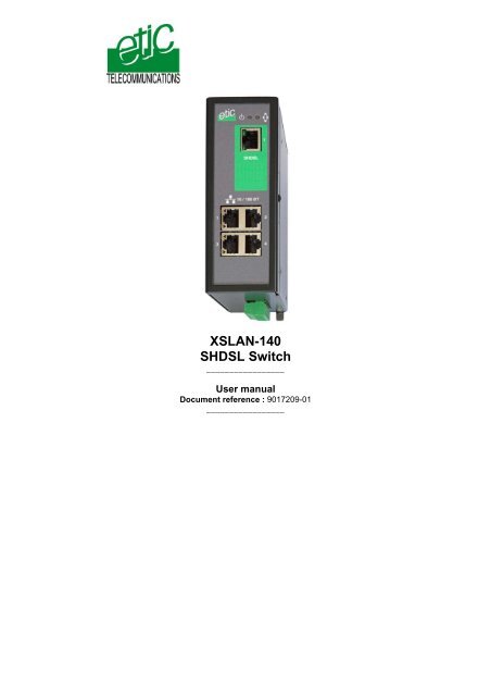
XSLAN-140 SHDSL Switch - Etic Telecom
XSLAN-140 SHDSL Switch - Etic Telecom
XSLAN-140 SHDSL Switch - Etic Telecom
- No tags were found...

Create successful ePaper yourself
Turn your PDF publications into a flip-book with our unique Google optimized e-Paper software.
The <strong>XSLAN</strong>-<strong>140</strong> <strong>SHDSL</strong> switch is manufactured byETIC TELECOMMUNICATIONS13 Chemin du vieux chêne38240 MEYLANFRANCETEL : + 33 4-76-04-20-00FAX : + 33 4-76-04-20-01e-mail : infos@etictelecom.comweb : www.etictelecom.comHotlineTEL : + 33 4-76-04-20-05FAX : + 33 4-76-04-20-01e-mail : hotline@etictelecom.comPage 2 User manual ref 9017209-01 <strong>XSLAN</strong>-<strong>140</strong> shdsl switch
Page 4 User manual ref 9017209-01 <strong>XSLAN</strong>-<strong>140</strong> shdsl switch
OVERVIEW1 Delivery content<strong>Switch</strong> <strong>SHDSL</strong> 1Câble pour ligne <strong>SHDSL</strong> 1User manual 1Accessories to order separatelyAdditional surge voltage arresterreferencePS02-12 Product overviewThe <strong>XSLAN</strong>-<strong>140</strong> shdsl switch enables to extend an Ethernet networkover kilometres using one simple voice-grade twisted pairs(telephone line).Distance and data rate<strong>SHDSL</strong> features an adaptive data rate from 128 Kb/s up to 2.3 Mb/s.The data rate is a function of the cable quality and the distance with theother <strong>SHDSL</strong> switch. For instance, the maximum distance between 2switches through a line is 13 Km (8 miles) with a 0.9 mm wire diametercable.The table in appendix 1 gives the data rate which can be expected over aline versus the length of the line (distance between 2 switches).Ethernet portsThe <strong>XSLAN</strong>-<strong>140</strong> provides 4 ethernet RJ45 interfaces (depending on theproduct reference).DIP swithes configurationThe <strong>XSLAN</strong>-<strong>140</strong> is configured with a few DIP switches.An html server for diagnosticThe <strong>XSLAN</strong>-<strong>140</strong> html server provides diagnostic pages giving theguarantee the transmission quality is what it has to be.<strong>XSLAN</strong>-<strong>140</strong> shdsl switch User manual ref 9017209-01 Page 5
OVERVIEW3 Data sheetDimensions 137 x 48 x 116 mm (h, l, d)C.E.MEN50082-2Electrical safety EN 60950Thunder EN61000-4 et -5Supply voltageConsumptionOperating T°<strong>SHDSL</strong>Connection delayLatency delaythrough the lineEthernet<strong>Switch</strong>ConfigurationDiagnostic9 to 40 VDC4W-20°/ + 60°C non condensingITU-T G.991.2, 802.3ah : 2BaseTL (EFM)Data rate : 128 kb/s to 2.3 Mb/s with 2 wiresAuto-mode : 1 mnFixed data rate : 30 s4 ms at 2.3Mb/s6 ms at 512 kb/s4 RJ45 10/100 Mb/s Half/Full duplex Auto MDI/MDIXStore and forward - 1024 MAC @Dip switchesHtml serverPage 6 User manual ref 9017209-01 <strong>XSLAN</strong>-<strong>140</strong> Shdsl switch
INSTALLATION1 Product description<strong>XSLAN</strong>-<strong>140</strong> shdsl switch User manual ref 9017209-01 Page 7
INSTALLATION1.1 Leds<strong>SHDSL</strong> Errorsport 1 & port 2OPERATION ledNot used<strong>SHDSL</strong> connectionleds1<strong>SHDSL</strong>Ethernet activity ledport 1 & port 2Ethernet activity ledport 3 & port 410 / 100 BT1 23 4Function LedDescriptionEthernet LINK/DATA Ethernet activityShdsl line led Green lower led :Slowly blinking : Shdsl connection in processLit on : Shdsl connection setQuickly blinking : Traffic over the <strong>SHDSL</strong> linkShdsl error ledRed upper led :Off : Error-free transmissionQuickly blinking : Transmission errorsOperationGreen : Ready for useRed : AlarmPage 8 User manual ref 9017209-01 <strong>XSLAN</strong>-<strong>140</strong> Shdsl switch
INSTALLATION1.2 Connectors8 pins screw blockSupply voltage and input / outputPin Nr Signal Function1 Power 1 + Supply voltage input 1 : 9 to 30 Vdc2 Power 1 - 0 V3 Power 2 + Supply voltage input 2 : 9 to 30 Vdc4 Power 2 - 0 V5678<strong>SHDSL</strong> RJ45 connectorPin Nr Signal Function1 N.C. -2 N.C. -3 N.C. -4 TIP <strong>SHDSL</strong> line5 RING <strong>SHDSL</strong> line6 N.C. -7 N.C. -8 N.C. -Ethernet RJ45 connectorPin Nr Signal Function1 Tx + TX polarity +2 Tx - TX polarity -3 Rx + Reception polarity +4 N.C -5 N.C -6 Rx - Reception polarity -7 N.C. -8 N.C. -<strong>XSLAN</strong>-<strong>140</strong> shdsl switch User manual ref 9017209-01 Page 9
INSTALLATION1.3 DIP switchesSW 1 SW 2ManagementDIP switchesOFF OFF The current IP@ of the product is the stored IP @ONOFFThe active IP@ of the product is the factory IP@ : 192.168.0.128No login and password are required to access to the html serverOFF ON The active IP@ is provided by the BOOTP or DHCP serverON ON No IP @ is assigned to the product; DIP switch configurationSW 3 SW 4 SW 5 Shdsl portOFF OFF OFF NTU modeOFF OFF ON LTU mode - AutoOFF ON OFF LTU mode – 2304 kbit/sOFF ON ON LTU Mode – 2048 kbit/sON OFF OFF LTU Mode – 1536 kbit/sON OFF ON LTU Mode – 1024 kbit/sON ON OFF LTU Mode – 512 kbit/sON ON ON LTU Mode – 256 kbit/sSW 6 to SW12Not used - Must be left OFFPage 10 User manual ref 9017209-01 <strong>XSLAN</strong>-<strong>140</strong> Shdsl switch
INSTALLATION2 VentilationTo avoid overheating when the ambient temperature is high, leave a 1 cm(0.5 inch) space on each side of the product.3 Supply voltageThe product comes with 2 separate voltage inputs, so that 2 externalpower supply modules can be connected to the product. If one powersupply module fails, the <strong>XSLAN</strong>-<strong>140</strong> will be powered by the other.The supply voltage must be strictly lower than 30 VDC and higher than 9VDC. The consumption is 170 mA at 24 VDC.4 FuseThe product is protected with a 3A fuse located on the electronic boardnear the supply voltage connectors.!!! A replacement fuse is available on the board ; it is located over the leds.5 Ethernet portsThe <strong>XSLAN</strong>-<strong>140</strong> features two or four auto-sensing 10/100 MbpsMDI/MDIX LAN ports.<strong>XSLAN</strong>-<strong>140</strong> shdsl switch User manual ref 9017209-01 Page 11
INSTALLATION6 <strong>SHDSL</strong> line connectionThe <strong>XSLAN</strong>-<strong>140</strong> is delivered with 1 line cable (reference CAB614).That cable ends with 2 wires.The 2 wires have to be connected to the 2 wires of the twisted pair line.The wires can be inverted.Shield :If the cable is shielded, the shield must be connected, at one end, directlyto the earth.Surge voltage arresterif the line is exposed to thelightning, we advise to usean over voltage arrester ateach end of the line.We have selected the Phoenix Contactmodule TT-2-PE-24D; it must be wired asindicated opposite.Page 12 User manual ref 9017209-01 <strong>XSLAN</strong>-<strong>140</strong> Shdsl switch
STARTUP1 Setting up the <strong>SHDSL</strong> connectionThe <strong>XSLAN</strong>-<strong>140</strong> is configured with DIP switches.The DIP swiches are located on the top side of the product.In case of difficulties, the diagnostic html server offers very usefuldiagnostic functions like Error rate statistics, signal quality and connectionlogs.To access to the html server, an IP address must be assigned to theproduct.Step 1 : Adjusting the “management” DIP switches SW01 and SW02settingsSW01 and SW02 must be usually set ON and ON. In that case, no IPaddress is assigned to the product.However, in case of line disconnection or errors, the html diagnosticserver will help to solve the difficulties; in that case, an IP address can beassigned to the product according to the table below.SW 1 SW 2ManagementDIP switchesOFF OFF The current IP@ of the product is the stored IP @ONOFFThe active IP@ of the product is the factory IP@ : 192.168.0.128No login and password are required to access to the html serverOFF ON The active IP@ is provided by the BOOTP or DHCP serverON ON No IP @ is assigned to the product; DIP switch configuration<strong>XSLAN</strong>-<strong>140</strong> shdsl switch User manual ref 9017209-01 Page 13
STARTUPStep 2 : Adjusting the “<strong>SHDSL</strong>” DIP-switches SW3, SW4, SW5settingsWhen 2 <strong>XSLAN</strong>-<strong>140</strong> are connected to one anotherthrough a line, one has to be configured as an LTU(calling party) and the other one as an “NTU”. (calledparty).The product which is named “LTU” negotiates andforces the data rate over the line; the NTU can onlyaccept.Setting up the <strong>XSLAN</strong>-<strong>140</strong> 1 (LTU) :If SW3, SW4 and SW5 are set OFF, OFF and ON (auto mode), the<strong>XSLAN</strong> 1 (LTU) will negotiate the appropriate data rate with the <strong>XSLAN</strong> 2(NTU). The connection delay will be longer.To reduce the connection delay, select the appropriate position of SW03,SW04, SW05 according to the line length; Refer to the table in appendix1.SW 3 SW 4 SW 5Shdsl portOFF OFF ON LTU mode – Auto<strong>XSLAN</strong> 1OFF ON OFF LTU mode – 2304 kbit/sOFF ON ON LTU Mode – 2048 kbit/sON OFF OFF LTU Mode – 1536 kbit/sON OFF ON LTU Mode – 1024 kbit/sON ON OFF LTU Mode – 512 kbit/sON ON ON LTU Mode – 256 kbit/sPage 14 User manual ref 9017209-01 <strong>XSLAN</strong>-<strong>140</strong> Shdsl switch
STARTUPSetting up the <strong>XSLAN</strong> 2 :SW 3 SW 4 SW 5Shdsl portOFF OFF OFF NTU mode<strong>XSLAN</strong> 2Step 3 : Connecting the products to the lineConnect the products to the line using the CAB 614 cable.Nota bene : For test purposes, any straight RJ45 cable can be connectedto each <strong>XSLAN</strong>-<strong>140</strong> <strong>SHDSL</strong> RJ45 connector.Step 4 : Check the connectionThe lower green led of the <strong>SHDSL</strong> RJ45 connector blinks during the<strong>SHDSL</strong> negotiation and then remains lit when the connection isestablished.If the Line led (lower green led of the <strong>SHDSL</strong> RJ45 connector)blinks permanently, it means that the connection cannot beestablished; check the wires connection and eventually, set a lowerdata rate with the DIP switches SW03, SW04, SW05.If the Error led (upper red led of the <strong>SHDSL</strong> RJ45 connector)blinks, it means that errors occur on the line, check the wiresconnection and eventually, set a lower data rate with the DIP switchesSW03, SW04, SW05.Step 5 : exchange data through the lineConnect a PC to one of the <strong>XSLAN</strong>-<strong>140</strong> and transmit periodical PING tothe other <strong>XSLAN</strong>-<strong>140</strong>.Check an answer is received within less than 10 ms.<strong>XSLAN</strong>-<strong>140</strong> shdsl switch User manual ref 9017209-01 Page 15
MAINTENANCE1 Connecting a PC to the <strong>XSLAN</strong> server1.1 Connecting the PC directly to the Ethernet RJ45 of the <strong>XSLAN</strong>Step 1 : Check the DIP switches SW1 and SW2; they must be set to OFFand OFF to select the stored IP address, or, if necessary, to ON and OFFto restore the factory IP address.Coming from factory, the IP address of the <strong>XSLAN</strong>-<strong>140</strong> is 192.168.0.128.Step 2 : Create or modify the PC TCP/IP connectionAssign to the PC an IP @ in accordance with the <strong>XSLAN</strong>-<strong>140</strong> IP address.For the first configuration, assign or instance 192.168.0.127 to the PC.Step 3 : Connect the PC directlyto an <strong>XSLAN</strong> ethernet interfaceusing any Ethernet cable (straightor crosswired)Step 4 : Launch the html browserEnter the IP @ of the <strong>XSLAN</strong>-<strong>140</strong>.The Home page of theadministration server is displayed1.2 Connecting a PC through a LANCase of a LAN with a BOOTP or DHCP serverStep 1 : Set the DIP switches SW1 OFF and SW2 OFF to select DHCP /BOOTP operation.Step 2 : Launch ETIC FINDER to detect the <strong>XSLAN</strong> over the LAN.<strong>XSLAN</strong>-<strong>140</strong> shdsl switch User manual ref 9017209-01 Page 16
MAINTENANCEClick the product once detected.The Home page of the administration server is displayed.Note :If the home page cannot be displayed, refer to paragraph 4 below.Case of a LAN without BOOTP or DHCP serverThat method must be avoided for the first configuration, because thefactory IP address of the <strong>XSLAN</strong>-<strong>140</strong> can also have been assigned toanother product.Otherwise, launch the html browser and enter the IP address assigned tothe <strong>XSLAN</strong>-<strong>140</strong>.Or, launch the ETICFINDER utility.1.3 Wrong IP address or passwordWhen launching the html browser, the homepage of the html server maynot be displayed; the cause may be the IP address you enter or thepassword you use are wrong.if the <strong>XSLAN</strong>-<strong>140</strong> IP address you enter is wrong, you can recover thefactory IP address by setting SW01 ON and SW2 OFF.The factory IP address 192.168.0.128 will be restored as long as theSW01 micro-switch will be left ON. Once, SW01 will be set OFF, thestored IP address (the IP address which is displayed) will be used by theproduct.Wrong Login to the administration serverThe access to the administration server can be protected by a login andpassword; If the Login & or password entered to access to theadministration server have been rejected, it is possible to recover a freeaccess, by setting SW01 ON and SW2 OFF.Careful : The factory IP address 192.168.0.128 will also automatically beassigned to the product as long as SW01 will remain ON and SW2 OFF.<strong>XSLAN</strong>-<strong>140</strong> shdsl switch User manual ref 9017209-01 Page 17
MAINTENANCE2 Checking the transmission qualityThe transmission quality can be summarized by two data :The signal quality and the error rate.Select the Diagnostic menu and then Network status.Signal qualityOnce the connection is set, the “Link state” line gives the signal qualityfrom 1/5 (bad quality), to 5/5 (excellent).If the signal quality is 1/5 or 2/5, errors and disconnection can occur;decrease the data rate (DIP switches of the <strong>XSLAN</strong>-<strong>140</strong> declared as LTU)and check the line.If the signal quality is 3/5, the connection quality is sufficient. Neverthelessthe data rate can be decreased with the DIP switches to get a 4/5 signalquality.<strong>SHDSL</strong> errors rateTo check the error rate, click the “Show statistics” button.Click the Reset button to reset the counters.The “CRC <strong>SHDSL</strong> errors” counter gives the numbers of errors on the line.If the quality is good, the number of errors must not increase more thanonce every minute.3 Checking <strong>SHDSL</strong> line disconnectionsThe log menu shows dated connections and disconnections of the<strong>XSLAN</strong>-<strong>140</strong>.When the quality is good, the <strong>XSLAN</strong>-<strong>140</strong> must not disconnect.Page 18 User manual ref 9017209-01 <strong>XSLAN</strong>-<strong>140</strong> shdsl switch
MAINTENANCE4 Updating the firmwareStep 1 : Before starting, you need,A PC with a Web browser.An Ethernet cable or a switchThe FTP server software which can be downloaded from the « firmwarepage » of the ETIC « download area » web server.Step 2 : Download the release of the firmware from our downloadarea to your PCStep 3 : Prepare the PCCheck the Ip address of the PC is compatible with the one of the router.Connect the router to the PC.Launch the TFTP server (tftp32.exe) software and select the new release(L026xxx/img) by using the "Browser" button.Click on "Show dir" to check the files of the directory : (jffs2root,rfsmini.tgz, u-boot.bin and uImage).Step 4 : Update the firmwareLaunch the web browserEnter the IP address of the ETIC product ; the home page of the ETICconfiguration server is displayed.Select the "System" menu and then " firmware Update". In the field "IPaddress of the TFTP server", enter the IP address of your PC.Note : The IP address of the PC is written in the field "Server Interface" inthe TFTP server windows.Click "Save" and then "Update".The first file should begin to be downloaded from the PC to the router.During the operation, the led blinksWhen the download is finished, the product automatically reboots.To be sure the new release has been installed, go to "About" in theadministration web page of the IP product.<strong>XSLAN</strong>-<strong>140</strong> shdsl switch User manual ref 9017209-01 Page 19
APPENDIX 1Data rate versus line length and cable qualityWire diam.mmDistance (Km)3 4 6 7 8 10 120,9 2.3Mb/s 2.3Mb/s 2.3Mb/s 1.5Mb/s 1.1Mb/s 512Kb/s 128Kb/s0,6 2.3Mb/s 2.3Mb/s 1.1Mb/s 256Kb/s 128Kb/s0,4 2.3Mb/s 1.1Mb/s 256Kb/s 128Kb/s<strong>XSLAN</strong>-<strong>140</strong> shdsl switch User manual ref 9017209-01 Page 21
ETIC TELECOM13 chemin du vieux chêne38240 Meylan -FranceTel 33 4 76 04 20 00Fax 33 4 76 04 20 01email : contact@etictelecom.comWeb : www.etictelecom.com