Drip (Trickle) Irrigation Systems
Drip (Trickle) Irrigation Systems
Drip (Trickle) Irrigation Systems
- No tags were found...

You also want an ePaper? Increase the reach of your titles
YUMPU automatically turns print PDFs into web optimized ePapers that Google loves.
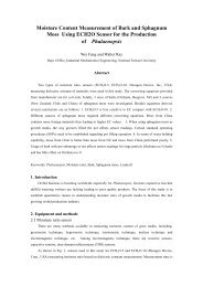
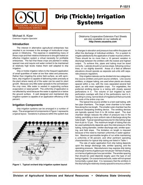
<strong>Drip</strong> (<strong>Trickle</strong>) <strong>Irrigation</strong><strong>Systems</strong>F-1511Michael A. KizerExtension <strong>Irrigation</strong> SpecialistIntroductionThe interest in alternative agricultural enterprises hasresulted in an increase in the acreage of horticultural cropsgrown in Oklahoma. The expense in establishing many ofthese crops and their relative intolerance to drought makes aneffective irrigation system a virtual necessity for profitableenterprises. The fact that these crops are planted in widelyspaced rows and require soil water content to be maintainedat relatively high levels makes them well adapted to dripirrigation.<strong>Drip</strong> or trickle irrigation refers to the frequent applicationof small quantities of water at low flow rates and pressures.Rather than irrigating the entire field surface, as with sprinklers,drip irrigation is capable of delivering water precisely atthe plant where nearly all of the water can be used for plantgrowth. Because very little water spreads to the soil betweenthe crop rows, little water is wasted in supporting surfaceevaporation or weed growth. The uniformity of application isnot affected by wind because the water is applied at or belowthe ground surface. A well designed and maintained dripirrigation system is capable of an application efficiency of 90percent.<strong>Irrigation</strong> Components<strong>Drip</strong> irrigation systems can be arranged in a number ofways. The arrangement of components in Figure 1 representsa typical layout. Variations in pressure within the system dueFigure 1. Typical orchard drip irrigation system layoutOklahoma Cooperative Extension Fact Sheetsare also available on our website at:http://www.osuextra.comto changes in elevation and pressure loss within the pipes willaffect the discharge of individual emitters. For a system toirrigate satisfactorily the application of water must be uniform.There should be no more than a 10 percent variation indischarge between the emitters with the lowest and highestoutput. To achieve this, pipes and tubing must be sizedcorrectly. Laterals should run across slope, following contourlines, or run slightly downhill. Areas of a field at differentelevations should operate as separate sub-units with separatepressure regulators.<strong>Drip</strong> irrigation laterals can be divided into two categories:line source emitters and point source emitters. Line sourceemitters, or dripper tubing, are used when plants are closelyspaced within a row, with the rows separated several feetapart, as with most vegetable crops. For vegetables, thepreferred emitting device is a tubing with closely spacedperforations in it. The volume of soil irrigated by eachperforation overlaps with that of the perforations next to it,resulting in a long, narrow block of irrigated soil that surroundsthe roots of the entire crop row.The typical line source emitter is a twin-wall tubing, withtwo pipe chambers. The larger, inner chamber is for waterflow along the row length. The smaller outer chamber has thepressure dissipating emitting device. The emitting devicesare typically spaced from 6 to 36 inches apart. The dualchamber design reduces the effect of pressure loss in thetubing, permitting a more uniform rate of discharge along thetube length. Typical operating pressures for drip tubing rangefrom 6 psi to 12 psi. The maximum length of tubing that canbe used satisfactorily depends upon the inlet pressure of thetubing, tubing diameter, emitter discharge rate, emitter spacing,and field slope. The limitation on length is imposedbecause of the need to maintain uniformity in water application.Maximum permissible lengths of run while maintaininga uniformity of 90 percent, and other pertinent operatingcharacteristics for typical drip tubing are listed in Table 1.The rate of water application from drip tubing dependsupon the design discharge rate, emitter spacing, and theoperating pressure. Manufacturers may express drip tubingdischarge in terms of gallons per minute per 100 feet of tubing,or in terms of gallons per hour per emitter. The emitter spacingthat should be used depends largely upon the type of soilbeing irrigated. On coarse textured soils, water will not spreadhorizontally a great deal. It is necessary that the emitters inthe drip tubing be relatively closely spaced to ensure a uniformDivision of Agricultural Sciences and Natural Resources • Oklahoma State University
Table 1. Maximum Length of <strong>Drip</strong> Tubing Laterals. (8 psiinlet pressure, level field slope)Emitter Emitter Emission UniformitySpacing Flow Rate 90% 85%(inch) (gph) Tubing Diameter Tubing Diameter5/8" 7/8" 5/8" 7/8"12-inch 0.22 750 ft 1300 ft 1000 ft 1750 ft0.45 500 ft 900 ft 650 ft 1150 ft24-inch 0.34 672 ft 1203 ft 850 ft 1521 ft0.50 519 ft 929 ft 657 ft 1175 ft36-inch 0.50 672 ft 1203 ft 850 ft 1521 ft1.00 427 ft 765 ft 541 ft 967 ftline of water is discharged along the row length to promoteeven crop growth. More than one drip tubing may be neededto uniformly irrigate wide planting beds on coarse texturedsoils because of limited capillary action. On finer texturedsoils, the capillary action of the small soil pores will permitgreater horizontal movement of the applied water from thepoint of emission. Water from each emitter could easilyspread to cover three feet or more of row length and width onfine textured soil.Recent developments in tubing manufacturing techniquesnow permit the production of drip tubing with turbulent flowproperties in the outer chamber at reasonable costs. Thesedevices are generally conceded to be superior to the originaldrip tubing with mechanical or laser drilled orifices. Theadvantages of turbulent drip tapes include larger openings atthe same rate of discharge, which makes them less susceptibleto blockages. They also exhibit improved pressurecompensating characteristics, which permits their use onlonger rows and irregular slopes.Point source emitters are used when widely spaced pointsources of water are needed, as in the case of orchard cropswhere the trees are spaced several feet apart. In this type ofsystem one or more emitting devices are attached to apipeline at or near the base of the plant, irrigating a bulb of soilsurrounding the root mass of the plant.Emitting devices for widely spaced plants are normallyattach onto polyethylene (PE) tubing. Most deliver either 1/2gallon per hour (gph), 1 gph, 2 gph, or 4 gph at their designoperating pressure. The maximum length of run for a singlelateral depends upon the emitter design, emitter dischargerate, emitter spacing, tubing diameter, lateral inlet pressure,and field slope. Maximum permissible length of laterals fortwo example crop layouts are given in Table 2. In both cases,the emitters are high quality (coefficient of variation = 0.05),non-pressure compensating emitters (emitter exponent =0.5).Emitters for trees should be located to provide balancedroot development. While a single, small capacity emitter maybe sufficient during the early years of plant development, ahigher flow rate will be needed as the tree matures. This largeflow should be divided between several emitters, spacedaround the trunk within the canopy dripline. The dripline issimply the line marking the extent of the tree canopy coverageon the ground surface.Table 2. Maximum Length of Level, Point Source LateralsGrapesPecans2-gph emitter/5 ft, 8 x 4-gph emitters/tree,C v=0.05, x=0.5 70-ft tree spacing,C v=0.05, x=0.5Nominal PETubing Lateral Inlet Pressure Lateral Inlet PressureDiameter 12 psi 15 psi 12 psi 15 psi1/2-in 415 ft 475 ft 560 ft 630 ft3/4-in 850 ft 980 ft 1330 ft 1400 ft1-in 1650 ft 1800 ft 2310 ft 2590 ftPressure RegulatorsSince drip irrigation systems operate at relatively lowpressures, even small variations in pressure can have asignificant effect on how uniformly the system applies water tothe crop. For this reason, pressure regulators are often used,especially on fields where the elevation varies considerably.For every 2.31 feet of elevation fall the pressure on water ina pipe will increase one pound per square inch (psi). For every2.31 feet of elevation rise the pressure decreases 1 psi. So,if a field has a variation of 10 feet in elevation from the highestto the lowest point, the emitters at the lowest point will beoperating at a pressure more than 4 psi greater than thehighest emitter. In a system which may have a designoperating pressure of only 8 psi, that is an extremely largevariation.Variations in pressure due to elevation change can behandled by using pressure regulators, or pressure compensatingemitters. Regulators are devices that maintain anoutlet pressure that is virtually constant as long as they aredriven by an input pressure higher than their output pressure.There are two common types of regulators used in dripsystems. There are adjustable regulators where the outputpressure is set by the irrigator, and preset regulators that havea fixed output pressure to match the pressure requirements ofthe emitting devices. Preset regulators are generally lessexpensive than adjustable regulators.Fields with elevation variations must be broken intosections with only slight variations of elevation within eachsection. A pressure regulator would be placed at the inlet toeach section, and the delivery system pressurized to maintainadequate pressure to the regulator in the section with thehighest elevation. All sections with lower elevations wouldhave their increased pressure reduced by the regulators anda reasonably uniform application of water would result.Pressure compensating emitters are emitting devicesthat maintain a virtually constant discharge as long as theiroperating pressure stays within a certain range. Most pressurecompensating emitters maintain an acceptable uniformityof discharge in the operating range of 10 psi to 30 psi.Pressure compensating emitters require no pressure regulator,but are substantially more expensive to purchase thanordinary emitters. On undulating fields where it is impossibleto create zones of uniform elevation pressure compensatingemitters are the only way to design a drip irrigation system withsatisfactory uniformity.1511-2
Water Quality and FiltrationWater quality and filtration are probably the most seriousconcerns when considering drip irrigation. In order to dischargevery low flow rates, the diameter of the emitter orificesmust be very small. This results in the emitters being blockedvery easily by even the smallest contaminants in the watersupply. Of particular concern are suspended solids, such assilt and sand, minerals that precipitate out of solution, such asiron or calcium, and algae that may grow in the water. Virtuallyevery drip irrigation system must include a filtration systemadequate to prevent plugging of the emitters. A system withpoor quality water and poor filtration simply will not functionreliably enough to warrant the maintenance requirementsneeded to keep it in operation.Manufacturers typically rate emitters with regard to thedegree of filtration required to prevent plugging by particles.This can be expressed in terms of a screen mesh number, oras the diameter of the width of the maximum filter opening.The relationship between the two sizing methods is given inTable 3.Filters may be constructed of stainless steel or plasticscreens that are reusable and require periodic cleaning. Theymay also use disposable fiber cartridges. For water that hasa heavy load of large contaminants, a separator, which usescentrifugal force to remove most of the particles, may be used.Moderately dirty water can be filtered by disk filters. Theseunits have a large number of thin plastic disks with grooves ofprecise dimensions cut into them. They are relatively easy toflush and reuse and are moderately expensive. Water withlarge amounts of fine silt and clay in suspension will normallyrequire filtration with a media filter. Media filters use gradedlayers of fine sand to remove sediment. They are effectivefilters, capable of handling very large flow rates, but arerelatively expensive to purchase and maintain. Suspendedsolids will normally be less of a problem when ground water isused for irrigation than when surface water is used.The precipitation of minerals in irrigation water is usuallya problem only with groundwater sources. Dissolved mineralsmay come out of solution with a change of pH or temperatureor when aeration occurs. If calcium is the problem, injectingacid into the water to lower the pH will prevent precipitates fromforming. Sometimes there is not sufficient calcium to precipitateout of solution, but enough to form a “lime” crust over theopenings of emitters after the system is shut off and thecomponents dry. If this situation causes frequent blockage ofemitters, injection of acid into the system for the final fewminutes of operation before shutdown should eliminate theproblem.Table 3. Filter Size Conversions.Mesh SizeMaximum Opening Width(inch)(microns)40 0.0150 38060 0.0100 26080 0.0070 180100 0.0060 140140 0.0041 105200 0.0029 74400 0.0011 27If iron is the problem, oxidizing the iron by chlorination oraeration and then filtering the water will be necessary. Injectionof chemicals such as fertilizers or pesticides into the watermay cause precipitation of minerals. Consequently, anyfiltration should take place after chemical injection has beendone. Occasional flushing of the system by opening the endsof the lateral lines to discharge accumulated sediment andprecipitates is recommended.Growth of algae within the irrigation system is seldom aproblem, since most algae require sunlight to grow, andvirtually all system components are made of opaque materials.However, if surface water is used to irrigate, algae quiteoften exist in the water supply. Pumping unfiltered water froman algae laden source will result in frequent blockage problems,so adequate filtration is important. Treatment of pondswith algae problems by the addition of copper sulfate willgreatly reduce the filtration load if the pond is used for dripirrigation.A bacterial slime may develop in systems where the waterhas considerable organic matter. Routine use of a 2 ppmchlorine rinse at the end of each irrigation set will normallyprevent slime development. If a slime problem does develop,a 30 ppm chlorine treatment will clean the system.The use of high quality water and an adequate filtrationsystem cannot be over emphasized. Use of poor qualityirrigation water in a drip irrigation system can result in so manymaintenance problems related to emitter plugging that anylabor savings you would expect relative to other irrigationmethods will be eliminated. Maintaining the filtration systemsatisfactorily, chemically treating the water if necessary, andfrequent flushing of the system will go a long way towardeliminating these problems.System CapacityThe hours of operation needed to meet the irrigationrequirement will depend upon the flow rate of the emittingdevice, the irrigation interval, and the rate of consumptivewater use by the crop. In no case should the total system bedesigned to operate more than 18 hours per day. This allowstime for system maintenance, and excess capacity for catchupin case of breakdowns. Nor should any zone be irrigatedfor more than 16 hours continuously, to allow some time foraeration of the crop root zone.When computing the daily water requirement, the calculationsare based only on the area of the field that is actuallycovered by vegetation. This is possible because only thevegetated area is irrigated with drip irrigation systems. Forexample, if tomatoes are planted in rows that are five feet apartbut the vegetation is only three feet wide, 100 feet of row lengthwould have an area of 300 square feet, not 500 square feet.It is assumed that the unvegetated strip between rows uses nowater and is not irrigated. If the tomatoes were estimated torequire 0.25 inch of water per day, the daily water requirementwould be 52.5 gallons per day per 100 feet of row length. Thisanswer is given by:Q = 0.7 W L DwhereQ = daily water requirement, gallonsW = row width of vegetation, feetL = length of row, feetD = depth of water use by crop, inch/day0.7 = constant (includes 90% efficiency)1511-3
If the tomatoes are to be irrigated every two days by a driptubing that emits 0.5 gpm per 100 feet of length, the operatingtime for the system would be 210 minutes (3.5 hours) perirrigation. This is determined from the equation:T = Q IRwhereT = operating time, minutes/irrigationQ = water requirement, gallons/day/100 feet of rowI = interval between irrigations, daysR = application rate of tubing, gpm/100 feetMaking the calculations based upon a unit row length of100 feet makes computations for a larger system simple. Forevery 100 feet of row length added in this system, another 0.5gpm of flow is needed from the water supply. Once themaximum capacity of the water supply is reached, the systemmust be divided into sub-units. Each sub-unit operatesindependently, in this case requiring 3.5 hours to apply sufficientwater for a two day period and is then shut off whileanother sub-unit is irrigated. For example, if the tomatoes to beirrigated were in a plot with 24 rows, each 240 feet long, thetotal row length would be 5,760 feet. At 0.5 gpm per 100 feet,the total flow rate required from the water supply would be 28.8gpm. If your water supply is capable of delivering only 10 gpm,not all of the system can be operated at once. If the plot isirrigated in three sub-units, each with eight rows, only 9.6 gpmis needed at one time. After the first sub-unit is irrigated for therequired 3.5 hours, it is switched off and the next sub-unit isirrigated for 3.5 hours and so on until all the sub-units havebeen irrigated. As long as there is sufficient time to cover allof the sub-units in the field before the interval between irrigations(2 days in this case) has elapsed, the water supply will beadequate for the entire field. In this example, the system couldirrigate up to 10 sub-units in two days without operating longerthan 18 hours per day.For widely spaced plants, such as orchard trees, waterrequirements are best determined on a “per plant” basis. Forexample, if a peach tree has a canopy that is 12 feet indiameter and uses water at a rate of 0.24 inches per day, dripirrigation must replace 18.8 gallons of water per day. Thisfigure is computed by the equation:Q = 0.544 D 2 dwhereQ = water requirement, gal/dayD = tree diameter, ftD = water use rate, in/day0.544 = constant (includes 90% efficiency)Each tree will require 18.8 gallons of water per day at thisstage of development. While a single 1 gph emitter couldprovide this amount of water, proper root system developmentwould be better promoted by dividing this flow amongthree or four emitters. The emitters should be placed out nearthe canopy dripline, equally spaced around the tree.The required operation time per irrigation will be givenby:T = QN RwhereT = Time of operation, hours/dayQ = Water requirement, gal/tree-dayN = Number of emitters per treeR = Emitter flow rate, gal/hourFor example, with four emitters of 2 gph flow capacity,the required 18.8 gallons would be applied in 2.4 hours.If the irrigation interval is longer than one day, the time ofoperation per irrigation will be multiplied by the number ofdays that elapse between irrigations. If the trees in theexample above were to be irrigated every seven days, thesystem would need to operate 16.5 hours per irrigation.In the case of home gardening irrigation, maximumsystem capacity is limited by water system flow rate. Astandard outside hydrant has a maximum capacity of about5 gpm, and can operate a maximum of 1000 feet of drip tubingwith 0.30 gph emitters on a 12 inch emitter spacing (0.5 gpmper 100 feet of tubing length), or about 300 1-gph point sourceemitters.Summary<strong>Drip</strong> irrigation can be an extremely versatile productiontool in horticultural enterprises. It can stretch a limited watersupply to cover up to 25 percent more acreage than a typicalsprinkler system. It can reduce the incidence of many fungaldiseases by reducing humidity in the crop canopy and keepingfoliage dry. It allows automation of the irrigation system,reducing labor requirements. It delays the onset of salinityproblems when irrigation water of marginal quality must beused.<strong>Drip</strong> irrigation requires careful water treatment to preventemitter blockage problems. Frequent inspection of the systemis necessary to insure it is functioning properly. Improperdesign and component sizing can result in a system with pooruniformity of application and a much lower than expectedapplication efficiency.A properly designed and installed drip irrigation systemwill normally be substantially more expensive than a sprinklerirrigation system initially. However, the lower operating costand higher efficiency of the drip system can justify the addedexpense very quickly in many horticultural production systems.Oklahoma State University, in compliance with Title VI and VII of the Civil Rights Act of 1964, Executive Order 11246 as amended, Title IX of the Education Amendments of 1972, Americans withDisabilities Act of 1990, and other federal laws and regulations, does not discriminate on the basis of race, color, national origin, sex, age, religion, disability, or status as a veteran in any of itspolicies, practices or procedures. This includes but is not limited to admissions, employment, financial aid, and educational services.Issued in furtherance of Cooperative Extension work, acts of May 8 and June 30, 1914, in cooperation with the U.S. Department of Agriculture, Sam E. Curl, Director of Oklahoma CooperativeExtension Service, Oklahoma State University, Stillwater, Oklahoma. This publication is printed and issued by Oklahoma State University as authorized by the Dean of the Division of AgriculturalSciences and Natural Resources and has been prepared and distributed at a cost of 20 cents per copy. 09031511-4