A9900618 (Issue 3) - Triumph Instructions.com
A9900618 (Issue 3) - Triumph Instructions.com
A9900618 (Issue 3) - Triumph Instructions.com
- No tags were found...

Create successful ePaper yourself
Turn your PDF publications into a flip-book with our unique Google optimized e-Paper software.
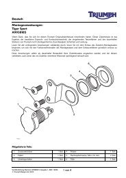
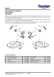
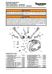
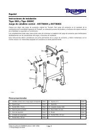
Indicator Relay Fitted to a Connector Block3. Remove the relay and retain it if the motorcycle is to bereturned to its original condition.6. Collect the relay and the rubber grommet fromkit A9830046. Fit the grommet to the relay with itsupper edge a minimum of 3 mm below the top of therelay as shown below.123 mm1celf_21. Direction indicator relay2. Relay connector block4. Fit the relay from the kit. The relay will fit only one way.Do not force fit the relay.T10021. Rubber grommet7. Collect the sub-harness from the kit and connect it tothe indicator relay, as shown below.Indicator Relay with an Electrical Connector5. Note the position of the indicator relay and detach itfrom its mounting. Disconnect the electrical connectorand remove the relay. Retain the relay if the motorcycleis to be returned to its original condition.2131T09991. Indicator relay, Tiger 800 shown2. Electrical connector2T1004_11. Sub-harness2. Brown lead3. Green lead8. Collect the ground cable from the kit. Align theM6 ring terminal end of the cable with the battery'snegative terminal. Following the main harness, routethe ground cable back to the relay mounting positionusing the cable ties to secure the ground cable whereappropriate.9. Ensure that there is enough cable to crimp thesupplied terminal and refit the relay to its mount. Trimoff any excess cable at the relay end.4 of 6