240 multi-purpose systems\HIWARM - komfovent
240 multi-purpose systems\HIWARM - komfovent
240 multi-purpose systems\HIWARM - komfovent
- No tags were found...

Create successful ePaper yourself
Turn your PDF publications into a flip-book with our unique Google optimized e-Paper software.
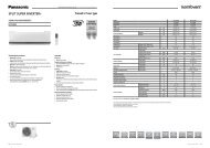
<strong>multi</strong>-<strong>purpose</strong> <strong>systems\HIWARM</strong>HIGH EFFICIENCY TOTAL HEAT RECOVERY MULTI-PURPOSEMODULATING SYSTEM> SPLIT VERSION> HEATING> COOLING> DEHUMIDIFICATION> DOMESTIC HOT WATER> USING RENEWABLE HEATING SOURCES> MAXIMUM ENERGY EFFICIENCY> TOTAL HEAT RECOVERY> INTEGRATED HYDRONIC SYSTEM> TOTAL SAFETYHiWarm is a <strong>multi</strong>-<strong>purpose</strong> total condensation heat recovery split heatpump.Exchanging heat with external air enables the room to be conditioned andto produce hot water for sanitary <strong>purpose</strong>s without the use of electricelements. During summer time the cooling system is capable of producinghot water and chilled water simultaneously.There are 3 sizes available, classified on the basis of cooling capacity tobe delivered at the maximum power frequency of the compressor.HIWARM 012HIWARM 022HIWARM 0332 kW30 Hz 110 Hz3 kW12 kW20 Hz 120 Hz5 kW22 kW33 kW20 Hz 120 HzThe characteristics shared by all 3 sizes of HiWarm units can be summedup as follows:- Indoor unit where the compressor is housed so as both to reduce outdoornoise emissions and allow the construction of a lightweight outdoor unitthat can be positioned above the ground with simple brackets.- Remote dissipator where the coil and the fans are housed. It is availablein a version for outdoor installation and in a duct version for indoorinstallation.Main constructive features of HiWarm units:- Double water circuit.- Air conditioning circuit with reversible system on cooling circuit sideand water side and min/max variable set-point through a voltage-freecontact or from min/max through a 0-10V or 4-20mA signal.- ACS circuit with total recovery (in the event of simultaneous cooling) orin any case with recovery as a priority. This circuit is separate and unlikein other similar products on the market it does not require long heating/cooling phases for inertial storage which impair energy efficiency, aboveall in summertime.- Scroll or twin-rotary compressors - BLDC brushless technology.- Exchangers with high efficiency braze-welded AISI 316 plates.- Highly efficiency fans.- Throttle valve: EEV (electronically controlled electric thermal expansionvalve) to take advantage from the possibility of generating thermodynamiccycles under reduced pressure let-downs, resulting in clear benefits interms of COP.- Integrated control of pumps on the system side and the DHW side:Both pumps are modulating pumps with permanent magnets electricsynchronous motor.- Advanced electronic control allowing to meet the load control steprequirements.These critical components guarantee an optimal performance under partload conditions, which are increasingly taken into consideration and are adiscriminating factor in the choice of thermal engineers.<strong>240</strong>VM66000305.00
<strong>multi</strong>-<strong>purpose</strong> <strong>systems\HIWARM</strong>WINTERHeating + domestic hot waterIN THE WINTER SEASON HIWARM CANPRODUCE HOT WATER FOR THE HEATINGSYSTEM AS WELL AS DOMESTIC HOT WATER,WITH OUTDOOR TEMPERATURES AS LOW AS-15°C AND WATER TEMPERATURES OF UP TO60°C.MILD CLIMATESdomestic hot water onlyDURING IN-BETWEEN SEASONS HIWARMCAN PRODUCE ONLY DOMESTIC HOT WATER,WHEREAS THE AIR CONDITIONING SYSTEM -SUMMER AND WINTER MODES - REMAINS OFFSUMMERDomestic hot water + coolingSUMMERDomestic hot water + cooling and dehumidificationIN THE SUMMERTIME OPERATING MODE,DOMESTIC HOT WATER AND CHILLED WATER AREPRODUCED AT "ZERO COST" SIMULTANEOUSLYAND USED FOR ROOM AIR COOLING AND/ORDEHUMIDIFICATION REQUIREMENTSVM66000305.00241
<strong>multi</strong>-<strong>purpose</strong> <strong>systems\HIWARM</strong>STRUCTURAL COMPONENTSINDOOR UNITGalvanised steel perimeter enclosure panels with an epoxy polyesterpowder coating, oven cured at 180°C, and front plexiglass cover whichalso incorporates the display (LCD).All components of the unit are accessible from the front of the unit, bysimply removing the front panel.The BLDC compressor, the high efficiency modulating pumps, the twobraze-welded plate exchangers, the electronic expansion valve, the onboardcontroller, the cycle reversing valve on the water side and the solenoidvalves are housed in the indoor unit.REMOTE UNIT FOR OUTDOOR INSTALLATIONPanels coated with epoxy polyester powder paint oven cured at 180°C.The unit is completely enclosed with panels and available in RAL9002(Grey White). The fans and the finned coil are housed in the outdoor unit.6 pole axial fans with blades ensuring broad coverage, associated withexternal rotor asynchronous motors (or synchronous permanent magnets)and fan continuous speed modulation.EC fans equipped with permanent magnets synchronous motors areavailable as option.REMOTE UNIT FOR INDOOR INSTALLATION (ATTIC)Galvanised sheet steel panelling, coated with epoxy polyester powder paintoven cured at 180°C.The unit is completely enclosed with panels and available in RAL9002(Grey White).Centrifugal fans with reaction impellers and backward curved bladescombined with brushless BLDC motors to ensure continuous efficientmodulation.Maximum head available at 200 Pa.COMPRESSORSHermetic scroll compressors (respectively for the 22 DC and 33 DC) ortwin rotary compressors (for the 12 DC), complete with motor protectionagainst temperature and current overloads and excessive temperatures ofthe outgoing gas.Mounted on rubber vibration dampers, complete with oil charge and housedin a compartment that is soundproofed with sound absorbing material. Theyare also equipped with an automatic oil heater to prevent the oil from beingdiluted by the refrigerant when the compressor stops.Brushless permanent magnet AC compressor motor controlled by atrapezoidal wave driver within a speed range between 30 (20) and 120 Hz(BLDC “Brushless Direct Current” technology).INTERNAL TEMPERATURE °CINVERTER MODELTRADITIONAL MODELTIMEINTERNAL EXCHANGERSAll units have heat exchangers with braze-welded AISI 316 austeniticstainless steel plates and connections made of AISI 304 L, characterisedby a reduced carbon content to facilitate brazing.Braze-welded plate exchangers represent the state of the art in terms ofheat exchange efficiency and make it possible to significantly reduce therefrigerant charge compared to traditional solutions.The high turbulence induced by the internal corrugation of the plates andthe perfectly smooth surface of the plates themselves also hinders thebuild-up of dirt. The high thermal exchange coefficient on the refrigerantside, in combination with the new plate geometry, enables a much shorterapproach to the T set-points, with clear benefits in terms of energy.PUMPSUse wet-rotor circulation pumpswith EC motors, maintenancefree, high efficiency (class A) andelectronically controlled.The pump casing is made ofgrey cast iron with a cataphoreticKTL coating, which providesoptimal protection againstcorrosion. The thermal insulationis polypropylene, the shaft isstainless steel, the bearings are made of metal-impregnated carbon andthe rotor, with a three-dimensional spiral is made of a synthetic materialwith a hermetic insulating coating of composite carbon fibre material.They are supplied with a heat-insulating shell for heating applications andinsulating preformed shells for cooling.ELECTRONICALLY CONTROLLED ELECTRIC THROTTLEVALVEAn electronically controlled electronic valve is usedinstead of a classic mechanical thermostatic valve,because it is able to handle transients in a shorter timeand to operate with very small P.The shutter in the central part of the valve can alwaysslide vertically with a wide range of movement to allowthe orifice through which the fluid passes to be openedby varying degrees.Using this valve makes it possible to reduce the amount of energyconsumed by the compressor when the surrounding conditions allowthe difference between the condensation and evaporation pressures to bereduced to values below 5 bar.242VM66000305.00
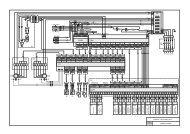
<strong>multi</strong>-<strong>purpose</strong> <strong>systems\HIWARM</strong>CYCLE REVERSING VALVE ONWATER SIDEHiWarm units are reversible: whenswitched from the cooling to heatpump mode and vice versa, theycarry out two cycle reversals. Oneon the refrigerant side and one onthe water side.The cycle reversing valve on thewater side is switched from positionA to position B (in less than 20seconds) and vice versa by meansof an electric driver, without changingthe direction of flow for users; this allows the direction of flow to be reversedin the exchangers, so that it is always opposite the direction of flow of therefrigerant fluid.ONBOARD CONTROLLERThe WEB circuit card allows a connection to be made between theonboard controller of the unit and the 10 Mbps Ethernet RJ45 network.The operating system used is Linux 2.4.21 .Installation takes place directly on the serial port of the advancedcontroller and a static or dynamic IP address with DHCP function isused.The supervision software permits the following:With supervision software it is also possible to perform supervisorymonitoring using the following protocols:Functions of on-board control system:- Control of the different operating parameters- Modulation of the compressor to maintain the outlet temperature setpoint of heat pump- Management of alarms (high/low pressure, antifreeze, flow switch, pumpalarm)- Management of pumps- Display of operating parameters- Antifreeze protection of heat exchangers- Management of the maximum number of compressor start-ups- Serial output management (optional)- Interfaceability via WEB with the Webgate option; all it takes is a simpleconnection and any Internet browser can be used- Summer/winter and on/off switching through clean contact or on-boardcontrolTHE SUPERVISION SOFTWARE integrated into the unit is available.VM66000305.00243
<strong>multi</strong>-<strong>purpose</strong> <strong>systems\HIWARM</strong>TECHNICAL DATAThermodynamic performances of HiWarm units equipped with electronic pumps (standard) and electronic control fans (optional) have been reportedin accordance with standard EN14511-<strong>240</strong>0. ESEER values have been calculated in accordance with Eurovent standards. Performances have beencalculated for a maximum length of 10 m for the gas lines connecting the internal unit to the remote one (internal or external).012 022 033Compressor speed [Hz] 30 110 30 120 30 120ESEER radiant panels (user @ 23-18°C) * 8.61 6.69 6.52ESEER Eurovent fan-coils (user @ 12-7°C) 5.65 5.30 5.24Cooling capacity [kW] 3.0 11.2 6.0 20.4 9.6 31.9Cooling + DHW @ 50/55°C and 12/7°C DHW @ 50/55°C and 30°C outdoor air Cooling @ 35°C air 23/18°C water Cooling @ 35°C air 12/7°C waterCompressor input power [kW] 0.6 3.1 1.3 7.0 2.1 11.0Compressor input current [A] 7.4 8.3 11.1 12.6 16.6 19.8Fan input power [kW] 0.08 0.30 0.07 0.45 0.06 0.60Fan input current [A] 0.40 1.40 0.10 0.80 0.10 1.10EER [-] 4.41 3.26 4.38 2.71 4.50 2.72USER water flow rate [kg/h] 519 1921 1026 3517 1646 5480USER water pressure drops [kPa] 2.0 19.0 3.0 26.0 3.0 23.0DISSIPATION air flow rate [m 3 /h] 3500 7000 5250 10500 7000 14000Cooling capacity [kW] 4.2 15.7 8.5 28.1 8.6 44.0Compressor input power [kW] 0.6 3.2 1.3 7.5 1.2 11.8Compressor input current [A] 6.9 8.6 10.9 13.2 3.2 20.4Fan input power [kW] 0.08 0.30 0.06 0.45 0.05 0.60Fan input current [A] 0.40 1.40 0.10 0.80 0.10 1.10EER [-] 6.27 4.41 6.34 3.46 6.80 3.47USER water flow rate [kg/h] 714 2696 1458 4834 1472 7565USER water pressure drops [kPa] 3.0 37.0 4.0 49.0 11.1 44.0DISSIPATION air flow rate [m 3 /h] 3500 7000 5250 10500 7000 14000Heating capacity [kW] 3.3 16.6 7.6 32.3 11.8 51.7Compressor input power [kW] 0.9 4.3 2.1 9.5 3.2 14.2Compressor input current [A] 12.8 18.4 15.2 23.7 20.2 25.9Fan input power [kW] 0.08 0.30 0.06 0.45 0.05 0.60Fan input current [A] 0.40 1.40 0.10 0.80 0.10 1.10COP [-] 3.46 3.54 3.58 3.14 3.63 3.37DHW water flow [kg/h] 714 2860 1307 5563 2169 8885DHW pressure drops [kPa] 3.0 41.0 4.0 64.0 4.0 61.0DISSIPATION air flow rate [m 3 /h] 3500 7000 5250 10500 7000 14000Cooling capacity [kW] 2.4 9.2 4.7 17.1 7.9 28.1Heating capacity [kW] 3.2 13.1 6.4 25.5 10.6 40.9Compressor input power [kW] 0.9 4.1 1.8 8.9 2.9 13.4Compressor input current [A] 10.6 11.0 14.8 15.3 22.7 23.7Fan input power [kW] 0.0 0.0 0.0 0.0 0.0 0.0Fan input current [A] 0.0 0.0 0.0 0.0 0.0 0.0COP [-] 3.55 3.16 3.49 2.86 3.68 3.03USER water flow rate [kg/h] 407 1580 806 2944 1357 4839USER water pressure drops [kPa] 1.0 13.0 3.0 18.0 3.0 18.0DHW water flow [kg/h] 556 2252 1107 4393 1829 7026DHW pressure drops [kPa] 2.0 26.0 4.0 40.0 4.0 38.0* Value calculated according to the same procedure as ESEER Eurovent Fan-coils (user @ 12-7°C).244VM66000305.00
<strong>multi</strong>-<strong>purpose</strong> <strong>systems\HIWARM</strong>TECHNICAL DATA012 022 033Compressor speed [Hz] 30 110 30 120 30 120ESEER radiant panels (user @ 23-18°C) * 8.61 6.69 6.52ESEER Eurovent fan-coils (user @ 12-7°C) 5.65 5.30 5.24BT Heating @ 30-35°C and 7°Coutdoor airBT Heating @ 30-35°C and 7°Coutdoor airElectricalinputNoiseemissionsHeating capacity [kW] 2.9 11.7 5.8 22.7 9.4 34.9Compressor input power [kW] 0.7 3.3 1.5 7.1 2.3 10.8Compressor input current [A] 8.6 8.9 12.3 12.7 18.9 19.6Fan input power [kW] 0.30 0.30 0.45 0.45 0.60 0.60Fan input current [A] 1.40 1.40 0.80 0.80 1.10 1.10COP [-] 2.84 3.23 3.00 2.95 3.21 3.02USER water flow rate [kg/h] 499 2014 1000 3903 1618 5998USER water pressure drops [kPa] 2.0 21.0 4.0 32.0 4.0 28.0DISSIPATION air flow rate [m 3 /h] 7000 7000 10500 10500 14000 14000Heating capacity [kW] 3.1 12.2 6.1 23.5 9.8 35.7Compressor input power [kW] 0.6 2.7 1.2 5.8 1.9 8.9Compressor input current [A] 7.2 7.5 10.6 11.0 15.8 16.5Fan input power [kW] 0.30 0.30 0.45 0.45 0.60 0.60Fan input current [A] 1.40 1.40 0.80 0.80 1.10 1.10COP [-] 3.48 4.03 3.69 3.65 3.91 3.71USER water flow rate [kg/h] 527 2093 1050 4034 1687 6147USER water pressure drops [kPa] 2.0 22.0 4.0 34.0 4.0 29.0DISSIPATION air flow rate [m 3 /h] 7000 7000 10500 10500 14000 14000Power supply single-phase 230/1/50 three-phase 400/3/50 three-phase 400/3/50FLA with fans adjusted by potentiometer[A] 21,8 23,0 33,2FLA with EC electronic fans [A] 21,2 22,0 31,8Lw sound power level - internal unit [dBA] 54 55 57Lp sound pressure level (10m Q=2)internal unit[dBA] 26 27 29Lw sound power level - external unit [dBA] 65 66 69Lp sound pressure level (10m Q=2)external unit[dBA] 37 38 41Compressor type Twin Rotary Scroll ScrollCompressorDimensions,weights andconnectionsElectric motor type BLDC BLDC BLDCOil charge for compressor [l] 1.8 1.5 1.8No. of cooling circuits 1 1 1Internal module dimensions (LxDxH) [mm] 803x1120x501.5 803x1247x606 803x1247x606External module dimensions (LxDxH) [mm] 1120x1230x450 1410x1280x450 2000x1512x550Weight of internal module [kg] 190 260 270Weight of external module [kg] 50 100 123Dimensions of hydraulic connectors [mm] 28 35 35Cooling connections Rotalock Rotalock Rotalock* Value calculated according to the same procedure as ESEER Eurovent Fan-coils (user @ 12-7°C).VM66000305.00245