PMBT1200 POWER MINI-BANDING TOOL - Daniels Manufacturing ...
PMBT1200 POWER MINI-BANDING TOOL - Daniels Manufacturing ...
PMBT1200 POWER MINI-BANDING TOOL - Daniels Manufacturing ...
- No tags were found...

You also want an ePaper? Increase the reach of your titles
YUMPU automatically turns print PDFs into web optimized ePapers that Google loves.
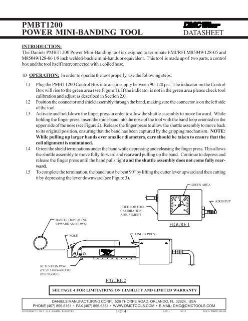
<strong>PMBT1200</strong><strong>POWER</strong> <strong>MINI</strong>-<strong>BANDING</strong> <strong>TOOL</strong>DATASHEET2.2.32.2.4Using a blade screwdriver, insert through the hole in the side of the control box (see Figure 1) androtate until it engages the slot in the air regulator adjustment knob. Rotate the knob of the regulatorclockwise to increase the tension reading and counterclockwise to decrease the reading until thedesired readings are attained to meet calibration requirements of Paragraph 2.1.5. (NOTE: If thecontrol box gage indicating needle does not fall within the green banded area, the <strong>PMBT1200</strong>should be returned to DMC for repair and recalibration).Depress and release the finger press of the tool to verify the reading. Readjust as necessary.Release the gage as described in Paragraphs 2.1.6 & 2.1.7.BAND INSERTION SLOTDBS-CG3CALIBRATIONINSPECTIONFIXTURE<strong>BANDING</strong><strong>TOOL</strong> NOSECUTTER LEVERFINGER PRESSBAND BUCKLEBACKSTOPGAGE VERIFICATIONSLOT<strong>PMBT1200</strong> <strong>POWER</strong> <strong>BANDING</strong> <strong>TOOL</strong>GO/NO-GO GAGEGOGAGE P/N: G752NO-GOFIGURE 42.3 ALTERNATE METHOD TO CHECK AND ADJUST <strong>PMBT1200</strong> CALIBRATION (DBS-CG1)2.3.1 Place the banding tool calibration fixture (P/N DBS-CG1) in a position where the dial of the gage isfacing the operator as shown in Figure 5.2.3.2 Place the cam handle in the locked position.2.3.3 Ensure that the adaptor insert marked "-15" for <strong>PMBT1200</strong> is installed in the fixture.2.3.4 Insert a piece of unused banding material 3 to 4 inches long through the adaptor plate until it passesbeyond the teeth of the gripper jaws and stop. Check engagement of band by pulling on it a few times.2.3.5 Insert the other end of the band into the nose of the banding tool until engaged.2.3.6 Repeatedly actuate the finger press of the tool until the band pulls tight and the shuttle assembly of thetool does not come fully rearward.2.3.7 Read the position of the indicating needle on the gage. This value represents the maximum tension inpounds of the tool for that pull. Tool calibration should be 62 lbs. minimum2.3.8 Should the tool calibration not be correct, verify that the supply air pressure is 90 psi or higher. Ifsupply pressure is below 90 psi, increase to a minimum of 90 psi and recheck gage indicating needleof DBS-CG1.DANIELS MANUFACTURING CORP., 526 THORPE ROAD, ORLANDO, FL 32824, USAPHONE (407) 855-6161 • FAX (407) 855-6884 • WWW.DMC<strong>TOOL</strong>S.COM • E-MAIL: DMC@DMC<strong>TOOL</strong>S.COM3 OF 4COPYRIGHT © 2013 ALL RIGHTS RESERVED REV. C 01/13 DOC#: <strong>PMBT1200</strong>-DS
<strong>PMBT1200</strong><strong>POWER</strong> <strong>MINI</strong>-<strong>BANDING</strong> <strong>TOOL</strong>DATASHEET2.3.92.3.102.3.112.3.12If the gage indicating needle still reads below the 62 lbs. value, insert a blade screwdriver through thehole in the side of the control box (see Figure 1) and rotate until it engages the slot in the air regulatorknob. Rotate the knob clockwise to increase the tension reading to about 72 lbs.Depress and release the finger press to verify the reading. Readjust as necessary. NOTE: If thecontrol box gage indicating needle does not fall within the green area at the 72 lbs. adjustment,the <strong>PMBT1200</strong> tool should be return to DMC for repair and recalibration.)Release the pressure of the gage by slowly moving the cam handle to the release position allowing thegage needle to return to zero.Push the gripper jaws cam lever clockwise, then pull the band from the calibration fixture.The band may now be removed from the tool.LOCKCAM HANDLEGRIPPER JAW CAM LEVER<strong>MINI</strong>-BANDRELEASEDBS-CG1<strong>BANDING</strong> <strong>TOOL</strong>CALIBRATION GAGEADAPTORINSERTADAPTORPLATEFIGURE 5<strong>PMBT1200</strong>LIMITATION OF LIABILITY / LIMITED WARRANTY*DANIELS MANUFACTURING CORPORATION IS NOT LIABLE FOR CONSEQUEN-TIAL OR SPECIAL DAMAGES OF ANY NATURE OR KIND RESULTING FROM THE USEOF ANY OF ITS PRODUCTS. OWNERS AND USERS OF DMC PRODUCTS ASSUMEFULL RESPONSIBILITY FOR INSTRUCTING THEIR EMPLOYEES IN THE PROPER ANDSAFE USE OF SUCH PRODUCTS.<strong>Daniels</strong> <strong>Manufacturing</strong> Corporation warrants each new unit sold by it to be free from defects in materialand workmanship under normal use and service. Its obligation under this warranty is limited to the freecorrection or, at its option, the refund of the purchase price of any such unit which proves defective withinninety (90) days after delivery to the first user, provided that the unit is returned to it with all transportationcharges prepaid, and which shall appear to its satisfaction, upon inspection by it, to have been defective inmaterial or workmanship. This warranty shall not cover any damage to such products, which in the opinionof <strong>Daniels</strong> <strong>Manufacturing</strong> Corporation, was caused by normal wear, misuse, improper operation or accident.This warranty is in lieu of all other warranties express or implied. No warranty, express or implied, ismade or authorized to be made or assumed with respect to products of <strong>Daniels</strong> <strong>Manufacturing</strong> Corporation,other than that herein set forth.*as defined by PL93-637DANIELS MANUFACTURING CORP., 526 THORPE ROAD, ORLANDO, FL 32824, USAPHONE (407) 855-6161 • FAX (407) 855-6884 • WWW.DMC<strong>TOOL</strong>S.COM • E-MAIL: DMC@DMC<strong>TOOL</strong>S.COMCOPYRIGHT © 2013 ALL RIGHTS RESERVED4 OF 4 REV. C 01/13 DOC#: <strong>PMBT1200</strong>-DS