design of dielectric probe for near-field measurement
design of dielectric probe for near-field measurement
design of dielectric probe for near-field measurement
- No tags were found...

You also want an ePaper? Increase the reach of your titles
YUMPU automatically turns print PDFs into web optimized ePapers that Google loves.
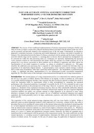
DESIGN OF DIELECTRIC PROBE FORNEAR-FIELD MEASUREMENTQian Qiaoyuan and Wen Mo *Shanghai Spaceflight Institute <strong>of</strong> TT&C and TelecomShanghai, China
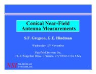
OutlineIntroductionPattern CharacteristicsRCS CharacteristicsCross-Polarization DesignDielectric Probe with Waveguide FeedSummarySHANGHAI SPACEFLIGHT INSTITUTE OF TT&C AND TELECOM, CHINA
1. Introduction (Ⅱ)The <strong>probe</strong> should have• Low RCS -- Lower multiple reflection error• Same E/H plane pattern -- Uni<strong>for</strong>m response <strong>for</strong> waves fromdifferent directions• Low cross-polarization -- Only one scan is needed <strong>for</strong> onepolarization <strong>measurement</strong>SHANGHAI SPACEFLIGHT INSTITUTE OF TT&C AND TELECOM, CHINA
2. Pattern Characteristics (Ⅰ)The Dielectric Rod ProbeDielectric Rod ConfigurationSHANGHAI SPACEFLIGHT INSTITUTE OF TT&C AND TELECOM, CHINA
2. Pattern Characteristics (Ⅱ)00E pl aneE pl ane-5H pl ane-5H pl aneAmpl i t ut e ( dB)-10-15-20Ampl t ude ( dB)-10-15-20c-25-25-30- 60 - 40 - 20 0 20 40 60Azi mut h ( deg)Far-Field Pattern <strong>of</strong> theDielectric Probe, E/H plane cut (18 GHz)-30- 60 - 40 - 20 0 20 40 60Azi mut h ( deg)Far-Field Pattern <strong>of</strong> theDielectric Probe , E/H plane cut (20 GHz)SHANGHAI SPACEFLIGHT INSTITUTE OF TT&C AND TELECOM, CHINA
2. Pattern Characteristics (Ⅲ)Far-Field Pattern <strong>of</strong> the Dielectric Probe (Taper Edged Waveguide)SHANGHAI SPACEFLIGHT INSTITUTE OF TT&C AND TELECOM, CHINA
3. RCS Characteristics (Ⅰ)• Lower multiple reflection error → Low RCS <strong>of</strong> <strong>probe</strong>• RCS control:• Proper Material -- Dielectric material• Proper Shape and Dimension -- Rod ShapeSHANGHAI SPACEFLIGHT INSTITUTE OF TT&C AND TELECOM, CHINA
3. RCS Characteristics (Ⅱ)(a) E Plane(b) H PlaneRCS SimulationRCS Simulation Result <strong>of</strong>the Dielectric Probe (18GHz)SHANGHAI SPACEFLIGHT INSTITUTE OF TT&C AND TELECOM, CHINA
3. RCS Characteristics (Ⅳ)The Dielectric Rod Probe with Rectangular EdgeThe Dielectric Rod Probe with Tapered EdgeSHANGHAI SPACEFLIGHT INSTITUTE OF TT&C AND TELECOM, CHINA
3. RCS Characteristics (Ⅴ)RCS Measurement Result <strong>of</strong> the Dielectric Probe(Tapered Edge Waveguide)Black line - waveguide only without <strong>dielectric</strong> rodBlue line - complete <strong>probe</strong> with <strong>dielectric</strong> rodSHANGHAI SPACEFLIGHT INSTITUTE OF TT&C AND TELECOM, CHINA
3. RCS Characteristics (Ⅵ)Gated OutPosition <strong>of</strong> Time-GateSHANGHAI SPACEFLIGHT INSTITUTE OF TT&C AND TELECOM, CHINA
4. Polarization Design (Ⅰ)With no cross-polarization <strong>of</strong> the <strong>probe</strong>→ Only one scan is needed <strong>for</strong> a single-polarization antenna<strong>measurement</strong>v v v vE( θ, ϕ) E′ ( θ, π- ϕ)- E( θ, ϕ) E ′( θ, π- ϕ)=θ θ ϕ ϕ∞ ∞ rC cosθexp( jkz cosθ) g P ( )exp( jkx si nθcosϕ+jky si nθsi n ϕ)dx dy∫ ∫0−∞ −∞B 0 0 0 0 0SHANGHAI SPACEFLIGHT INSTITUTE OF TT&C AND TELECOM, CHINA
4. Polarization Design (Ⅱ)EM Field Changes vs. StructureChange <strong>of</strong> the WaveguideEM Field Changes at the Feed<strong>of</strong> the Dielectric RodEM Field changes at the End<strong>of</strong> the WaveguideSHANGHAI SPACEFLIGHT INSTITUTE OF TT&C AND TELECOM, CHINA
4. Polarization Design (Ⅲ)Far-<strong>field</strong> amplitude <strong>of</strong> 8x8G test20060103Probe-1.nsiFar-<strong>field</strong> amplitude <strong>of</strong> 8x8G test20060103Probe-1.nsi0main polcross pol0main polcross pol-5-5-10-10-15-15Amplitude (dB)-20-25-30Amplitude (dB)-20-25-30-35-35-40-40-45-45-50-50 -25 0 25 50Elevation (deg)-50-50 -25 0 25 50Azimuth (deg)(a) E plane(b) H planeMain/Cross Polarization Pattern<strong>of</strong> the Dielectric ProbeSHANGHAI SPACEFLIGHT INSTITUTE OF TT&C AND TELECOM, CHINA
5. Dielectric Probe with Waveguide Feed (Ⅰ)50-526GHz30GHz36GHz5-526GHz36GHz30GHzAplitute (dB)-10-15-20-25-30-3540GHzAmpi t ut e ( dB)-15-25-35-4540GHz-40- 180 - 150 - 120 - 90 - 60 - 30 0 30 60 90 120 150 180-55- 180 - 150 - 120 - 90 - 60 - 30 0 30 60 90 120 150 180Azi mut h ( deg)Azi mut h ( deg)Dielectric Rod Probe Fed byRectangular Waveguide(a) E planePattern <strong>of</strong> Dielectric Rod ProbeFed by Rectangular Waveguide(b) H planeSHANGHAI SPACEFLIGHT INSTITUTE OF TT&C AND TELECOM, CHINA
5. Dielectric Probe with Waveguide Feed (Ⅱ)(a) E plane(b) H planeCross-polarization Pattern Simulation Results (30GHz)SHANGHAI SPACEFLIGHT INSTITUTE OF TT&C AND TELECOM, CHINA
6. Summary• The square waveguide fed <strong>dielectric</strong> <strong>probe</strong> has low RCS, symmetricpattern, relatively high gain and low cross-polarization pattern.• Its only disadvantage is that the deep drops in the front pattern,which needs to be improved by further optimal work.• Another rectangular <strong>probe</strong> <strong>design</strong> is also good at low RCS and lowcross-polarization.SHANGHAI SPACEFLIGHT INSTITUTE OF TT&C AND TELECOM, CHINA