S15 Non-Metallic - Enviro Solutions
S15 Non-Metallic - Enviro Solutions
S15 Non-Metallic - Enviro Solutions
- No tags were found...

Create successful ePaper yourself
Turn your PDF publications into a flip-book with our unique Google optimized e-Paper software.
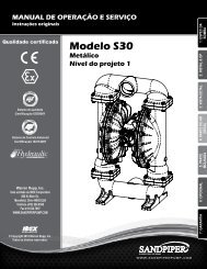
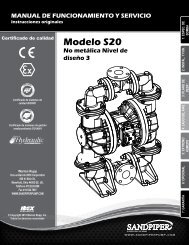
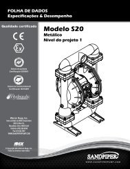
Quality SystemISO9001 Certified<strong>Enviro</strong>nmentalManagement SystemISO14001 CertifiedCEU.S. Patent #5,851,109; 5,996,627;400,210 & 6,241,487Other U.S. PatentsApplied for<strong>S15</strong> <strong>Non</strong>-<strong>Metallic</strong>Design Level 2Ball ValveAir-PoweredDouble-Diaphragm PumpAir Exhaust Side ViewAir Inlet Side ViewENGINEERING, PERFORMANCE& CONSTRUCTION DATAINTAKE/DISCHARGE PIPE SIZE1½" ANSI Flange orPN10 40mm DIN FlangeCAPACITY0 to 90 US gallons per minute(0 to 340 liters per minute)AIR VALVENo-lube, no-stalldesignSOLIDS-HANDLINGUp to .47 in. (12mm)HEADS UP TO100 psi or 231 ft. of water(7 bar or 70 meters)DISPLACEMENT/STROKE.36 US gallon / 1.36 literCAUTION! Operating temperature limitations are as follows:Materials Maximum*Operating TemperaturesMinimum* Optimum**Santoprene ® Injection molded thermoplastic elastomer with no fabric layer. Long mechanical flex 212°F -10°F 50° to 212°Flife. Excellent abrasion resistance. 100°C -23°C 10°C to 100°CPTFE Chemically inert, virtually impervious. Very few chemicals are known to react chemically withPTFE: molten alkali metals, turbulent liquid or gaseous fluorine and a few fluoro-chemicals such as 212°F -35°F 50°F to 212°Fchlorine trifluoride or oxygen difluoride which readily liberate free fluorine at elevated temperatures. 100°C -37°C 10°C to 100°CPVDF 200°F -10°F-93°C-13°CPolypropylene 150°F -40°F65°C 5°CPolyurethane 210°F99°C-40°F-40°C-40°F to 210°F-40°C to 99°CFor specific applications, always consult “Chemical Resistance Chart” Technical BulletinSandPIPER II ® pumps are designed to be powered only by compressed air.*Definite reduction in service life.**Minimal reduction in service life at ends of range.520-193-000 9/02 Model <strong>S15</strong> <strong>Non</strong>-<strong>Metallic</strong> Design Level 2 Page 1
Explanation of Pump Nomenclature<strong>S15</strong> <strong>Non</strong>-<strong>Metallic</strong> · Design Level 2· Ball ValveCheck Diaphragm/ Check <strong>Non</strong>-Wetted ShippingMODEL Pump Pump Valve Design Wetted Check Valve Valve Material Porting Pump Pump Kit WeightBrand Size Type Level Material Materials Seat Options Options Style Options Options lbs. (kg)<strong>S15</strong>B2P1PQAS000. S 15 B 2 P 1 P Q A S 0 00. 53 (24)<strong>S15</strong>B2K1KQAS000. S 15 B 2 K 1 K Q A S 0 00. 65 (29)<strong>S15</strong>B2P2PQAS000. S 15 B 2 P 2 P Q A S 0 00. 53 (24)<strong>S15</strong>B2K2KQAS000. S 15 B 2 K 2 K Q A S 0 00. 65 (29)<strong>S15</strong>B2P3PQAV000. S 15 B 2 P 3 P Q A V 0 00. 58 (26)<strong>S15</strong>B2K3KQAV000. S 15 B 2 K 3 K Q A V 0 00. 77 (35)<strong>S15</strong>B2P4PQAV000. S 15 B 2 P 4 P Q A V 0 00. 58 (26)<strong>S15</strong>B2K4KQAV000. S 15 B 2 K 4 K Q A V 0 00. 77 (35)Pump BrandS= SandPIPER II ®Pump Size15=1½"Check Valve TypeB= BallDesign Level2= Design Level 2Wetted MaterialK= PVDFP= PolypropyleneDiaphragm Check ValveMaterials1= Santoprene/Santoprene2= PTFE-SantopreneBackup/PTFE3= PTFE Pumping, PTFE-SantopreneBackup Driver/PTFE4= Santoprene Pumping,SantopreneDriver/SantopreneCheck Valve SeatK= PVDFN= NylonP= Polypropylene<strong>Non</strong>-Wetted Material OptionsA= Painted AluminumJ= Painted Aluminum PTFEQ=Epoxy Coated AluminumK= PTFE Coated AluminumL= PTFE Coated Aluminum withPTFE Coated HardwareR= Epoxy Coated Aluminum withPTFE Coated HardwarePorting OptionsA= ANSI FlangeD=DIN Flange7= Dual Porting (ANSI)8= Top Dual Porting (ANSI)9= Bottom Dual Porting (ANSI)Pump StyleD=RuppGUARD with ElectronicLeak Detection (110V)E= RuppGUARD with ElectronicLeak Detection 220V)M=RuppGUARD with MechanicalLeak DetectionS= StandardV= RuppGUARD with VisualLeak DetectionPump Options0= <strong>Non</strong>e1= 3M Muffler2= Mesh Muffler3= High temperature Air Valvew/Encapsulated Muffler4= High temperature Air Valvew/3M Muffler5= High temperature Air Valvew/Mesh MufflerKit Options00.=<strong>Non</strong>eP0.=0-30VDC Pulse Output KitP1.=Intrinsically-Safe 10-30VDCPulse Output KitP2.=110/120 or 220/240VACPulse Output KitP3.=Intrinsically-Safe 110/120VACPulse Output KitP4.=Intrinsically-Safe 220/240VACPulse Output KitE0.=Solenoid Kit with 24VDC CoilE1.=Solenoid Kit with 24VDC Explosion-Proof CoilE2.=Solenoid Kit with 24VAC/12VDC CoilE3.=Solenoid Kit with 24VAC12VDCExplosion-Proof CoilE4.=Solenoid Kit with 110VAC CoilE5.=Solenoid Kit with 110VAC Explosion-Proof CoilE6.=Solenoid Kit with 220VAC CoilE7.=Solenoid Kit with 220VAC Explosion-Proof CoilSP.=Stroke Indicator Pins520-193-000 9/02 Model <strong>S15</strong> <strong>Non</strong>-<strong>Metallic</strong> Design Level 2 Page 2
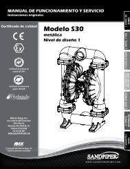
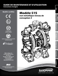
Performance Curve, Model <strong>S15</strong> <strong>Non</strong>-<strong>Metallic</strong>Design Level 2BARPSI710010 (17)100 PSI (6.8 Bar)20 (34)6908030 (51)40 (68)57080 PSI (5.44 Bar)50 (85)Head432106050403020100060 PSI (4.08 Bar)40 PSI (2.72 Bar)20 PSI (1.36 Bar)Air Inlet Pressure10 20 30405055 (93)60U.S. Gallons per minute60 (102)65 (110)55(93)45(76)69 (117)58 (99)70 80 90FEET30252015105METERS9.17.664.531.5NPSHR020406080100120140 160 180 200 220Liters per minute240260280300320340Capacity520-193-000 9/02 Model <strong>S15</strong> <strong>Non</strong>-<strong>Metallic</strong> Design Level 2 Page 3
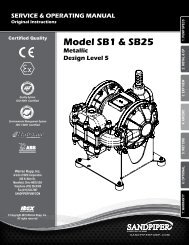
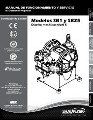
Dimensions: <strong>S15</strong> <strong>Non</strong>-<strong>Metallic</strong>Dimensions in InchesDimensional tolerance: ± 1 /8"23 7/8"DimensionStandard PumpPulse Output KitMesh MufflerAB6 9/16" 12 11/16"7 15/16" 14 1/16"8 13/16" 14 15/16"Note: Porting Flanges are also avaible withPN10 40mm DIN bolting configuration.520-193-000 9/02 Model <strong>S15</strong> <strong>Non</strong>-<strong>Metallic</strong> Design Level 2 Page 4
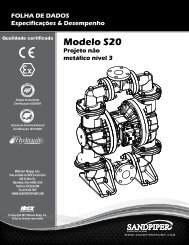
Metric Dimensions: <strong>S15</strong> <strong>Non</strong>-<strong>Metallic</strong>Dimensions in MillimetersDimensional tolerance: ±3mm606mmDimensionStandard PumpPulse Output KitMesh MufflerA167mm202mm225mmB322mm357mm380mmNote: Porting Flanges are also avaible withPN10 40mm DIN bolting configuration.520-193-000 9/02 Model <strong>S15</strong> <strong>Non</strong>-<strong>Metallic</strong> Design Level 2 Page 5
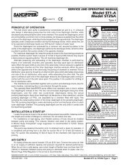
Dimensions: <strong>S15</strong> <strong>Non</strong>-<strong>Metallic</strong>with RuppGUARD Spill Prevention15 1/4"28 5/8"ABDimensionStandard PumpPulse Output KitMesh MufflerA B6 9/16" 12 11/16"7 15/16" 14 1/16"8 13/16" 14 15/16"Note: Porting Flanges are also avaible withPN10 40mm DIN bolting configuration.520-193-000 9/02 Model <strong>S15</strong> <strong>Non</strong>-<strong>Metallic</strong> Design Level 2 Page 6
Metric Dimensions: <strong>S15</strong> <strong>Non</strong>-<strong>Metallic</strong>with RuppGUARD Spill PreventionB728 mmADimensionABStandard PumpPulse Output Kit167mm202mm322mm357mmMesh Muffler 225mm 380mmNote: Porting Flanges are also avaible withPN10 40mm DIN bolting configuration.520-193-000 9/02 Model <strong>S15</strong> <strong>Non</strong>-<strong>Metallic</strong> Design Level 2 Page 7
PRINCIPLE OF PUMP OPERATIONThis ball type check valve pump ispowered by compressed air and is a 1:1ratio design. The inner side of onediaphragm chamber is alternatelypressurized while simultaneouslyexhausting the other inner chamber. Thiscauses the diaphragms, which areconnected by a common rod securedby plates to the centers of thediaphragms, to move in a reciprocatingaction. (As one diaphragm performs thedischarge stroke the other diaphragmis pulled to perform the suction strokein the opposite chamber.) Air pressureis applied over the entire inner surfaceof the diaphragm while liquid isdischarged from the opposite side of thediaphragm. The diaphragm operates ina balanced condition during thedischarge stroke which allows the pumpto be operated at discharge heads over200 feet (61 meters) of water.For maximum diaphragm life, keepthe pump as close to the liquid beingpumped as possible. Positive suctionhead in excess of 10 feet of liquid (3.048meters) may require a back pressureregulating device to maximizediaphragm life.Alternate pressurizing andexhausting of the diaphragm chamberis performed by an externally mounted,pilot operated, four way spool type airdistribution valve. When the spool shiftsto one end of the valve body, inletpressure is applied to one diaphragmchamber and the other diaphragmchamber exhausts. When the spoolshifts to the opposite end of the valvebody, the pressure to the chambers isreversed. The air distribution valve spoolis moved by a internal pilot valve whichalternately pressurizes one end of theair distribution valve spool whileexhausting the other end. The pilot valveis shifted at each end of the diaphragmstroke when a actuator plunger iscontacted by the diaphragm plate. Thisactuator plunger then pushes the end ofthe pilot valve spool into position toactivate the air distribution valve.The chambers are connected withmanifolds with a suction and dischargecheck valve for each chamber,maintaining flow in one direction throughthe pump.INSTALLATION AND START-UPLocate the pump as close to theproduct being pumped as possible. Keepthe suction line length and number offittings to a minimum. Do not reduce thesuction line diameter.For installations of rigid piping, shortsections of flexible hose should beinstalled between the pump and thepiping. The flexible hose reducesvibration and strain to the pumpingsystem. A surge suppressor isrecommended to further reducepulsation in flow.AIR SUPPLYAir supply pressure cannot exceed100 psi (7 bar). Connect the pump airinlet to an air supply of sufficient capacityand pressure required for desiredperformance. When the air supply lineis solid piping, use a short length offlexible hose not less than ½" (13mm)in diameter between the pump and thepiping to reduce strain to the piping. Theweight of the air supply line, regulatorsand filters must be supported by somemeans other than the air inlet cap. Failureto provide support for the piping mayresult in damage to the pump. A pressureregulating valve should be installed toinsure air supply pressure does notexceed recommended limits.AIR VALVE LUBRICATIONThe air distribution valve and the pilotvalve are designed to operate WITHOUTlubrication. This is the preferred mode ofoperation. There may be instances ofpersonal preference or poor quality airsupplies when lubrication of thecompressed air supply is required. Thepump air system will operate withproperly lubricated compressed airsupply. Proper lubrication requires theuse of an air line lubricator (available fromWarren Rupp) set to deliver one drop ofSAE 10 non-detergent oil for every 20SCFM (9.4 liters/sec.) of air the pumpconsumes at the point of operation.Consult the pump’s publishedPerformance Curve to determine this.AIR LINE MOISTUREWater in the compressed air supplycan create problems such as icing orfreezing of the exhaust air, causing thepump to cycle erratically or stopoperating. Water in the air supply canbe reduced by using a point-of-use airdryer to supplement the user’s air dryingequipment. This device removes waterfrom the compressed air supply andalleviates the icing or freezing problems.AIR INLET AND PRIMINGTo start the pump, open the air valveapproximately ½ to ¾ turn. After thepump primes, the air valve can be openedto increase air flow as desired. If openingthe valve increases cycling rate, but doesnot increase the rate of flow, cavitationhas occurred. The valve should be closedslightly to obtain the most efficient airflow to pump flow ratio.BETWEEN USESWhen the pump is used for materialsthat tend to settle out or solidify whennot in motion, the pump should be flushedafter each use to prevent damage.(Product remaining in the pump betweenuses could dry out or settle out. Thiscould cause problems with thediaphragms and check valves at restart.)In freezing temperatures the pump mustbe completely drained between uses inall cases.520-193-000 9/02 Model <strong>S15</strong> <strong>Non</strong>-<strong>Metallic</strong> Design Level 2 Page 8
INSTALLATION GUIDETop Discharge Ball Valve UnitAvailable fromWarren Rupp11234Surge Suppressor020-050-000 Filter/Regulator020-050-001 Lubricator020-047-007 Air DryerCAUTIONThe air exhaust should bepiped to an area for safedisposition of the productbeing pumped, in the eventof a diaphragm failure.234520-193-000 9/02 Model <strong>S15</strong> <strong>Non</strong>-<strong>Metallic</strong> Design Level 2 Page 9
IMPORTANTRead these safety warningsand instructions in thismanual completely, beforeinstallation and start-upof the pump. It is theresponsibility of the purchaser to retain thismanual for reference. Failure to comply withthe recommendations stated in this manual willdamage the pump, and void factory warranty.CAUTIONBefore pump operation,inspect all gasketedfasteners for loosenesscaused by gasket creep.Re-torque loose fastenersto prevent leakage. Follow recommendedtorques stated in this manual.WARNINGBefore maintenance orrepair, shut off the compressedair line, bleed thepressure, and disconnectthe air line from the pump.The discharge line may be pressurized andmust be bled of its pressure.WARNINGIn the event of diaphragmrupture, pumped materialmay enter the air end of thepump, and be dischargedinto the atmosphere. Ifpumping a product which is hazardous or toxic,the air exhaust must be piped to an appropriatearea for safe disposition.IMPORTANT SAFETYINFORMATIONWARNINGThis pump is pressurizedinternally with air pressureduring operation. Alwaysmake certain that all boltingis in good condition and thatall of the correct bolting is reinstalled duringassembly.WARNINGWhen used for toxic oraggressive fluids, the pumpshould always be flushedclean prior to disassembly.WARNINGBefore doing any maintenanceon the pump, becertain all pressure iscompletely vented from thepump, suction, discharge,piping, and all other openings and connections.Be certain the air supply is locked out or madenon-operational, so that it cannot be started whilework is being done on the pump. Be certain thatapproved eye protection and protective clothingare worn all times in the vicinity of the pump.Failure to follow these recommendations mayresult in serious injury or death.WARNINGAirborne particles and loudnoise hazards.Wear ear and eye protection.MATERIAL CODESThe Last 3 Digits of Part Number000 ........ Assembly, sub-assembly; and some purchaseditems010 ........ Cast Iron012 ......... Powered Metal015 ......... Ductile Iron020 ......... Ferritic Malleable Iron025 ........ Music Wire080 ........ Carbon Steel, AISI B-1112100 ........ Alloy 20110 ........ Alloy Type 316 Stainless Steel111 ........ Alloy Type 316 Stainless Steel (Electro Polished)112 ........ Alloy “C” (Hastelloy equivalent)113 ......... Alloy Type 316 Stainless Steel (Hand Polished)114 ......... 303 Stainless Steel115 ......... 302/304 Stainless Steel117 ......... 440-C Stainless Steel (Martensitic)120 ......... 416 Stainless Steel (Wrought Martensitic)123 ......... 410 Stainless Steel (Wrought Martensitic)148 ........ Hardcoat Anodized Aluminum149 ........ 2024-T4 Aluminum150 ........ 6061-T6 Aluminum151 ........ 6063-T6 Aluminum152 ........ 2024-T4 Aluminum (2023-T351)154 ........ Almag 35 Aluminum155 ........ 356-T6 Aluminum156 ........ 356-T6 Aluminum157 ........ Die Cast Aluminum Alloy #380158 ........ Aluminum Alloy SR-319159 ......... Anodized Aluminum162 ......... Brass, Yellow, Screw Machine Stock165 ........ Cast Bronze, 85-5-5-5166 ........ Bronze, SAE 660170 ........ Bronze, Bearing Type, Oil Impregnated175 ........ Die Cast Zinc180 ........ Copper Alloy305 ........ Carbon Steel, Gray Epoxy Coated306 ......... Carbon Steel, Black PTFE Coated307 ........ Aluminum, Gray Epoxy Coated308 ......... Stainless Steel, Black PTFE Coated309 ......... Aluminum, Black PTFE Coated310 ......... Kynar ® Coated330 ......... Zinc Plated Steel331 ........ Chrome Plated Steel332 ........ Aluminum, Electroless Nickel Plated333 ........ Carbon Steel, Electroless Nickel Plated335 ........ Galvanized Steel336 ........ Zinc Plated Yellow Brass337 ........ Silver Plated Steel340 ........ Nickel Plated342 ........ Filled Nylon353 ......... Geolast; Color: Black354 ........ Injection Molded #203-40 Santoprene - Duro 40D+/-5; Color: RED355 ........ Thermal Plastic356 ........ Hytrel357 ........ Injection Molded Polyurethane358 ........ Rupplon (Urethane Rubber). Color coded:PURPLE (Some Applications) (Compression Mold)359 ........ Urethane Rubber360 ........ Buna-N Rubber. Color coded: RED361 ........ Buna-N363 ........ Viton (Flurorel). Color coded: YELLOW364 ........ E.P.D.M. Rubber. Color coded: BLUE365 ........ Neoprene Rubber. Color coded: GREEN366 ........ Food Grade Nitrile368 ........ Food Grade EPDM370 ........ Butyl Rubber. Color coded: BROWN371 ........ Philthane (Tuftane)374 ......... Carboxylated Nytrile375 ........ Fluorinated Nitrile378 ........ High Density Polypropylene405 ........ Cellulose Fibre408 ........ Cork and Neoprene425 ........ Compressed Fibre426 ........ Blue Gard440 ........ Vegetable Fibre465 ........ Fibre500 ........ Delrin 500501 ........ Delrin 570502 ........ Conductive Acetal, ESD-800503 ........ Conductive Acetal, Glass-Filled505 ........ Acrylic Resin Plastic506 ........ Delrin 150520 ........ Injection Molded PVDF Natural color540 ........ Nylon541 ........ Nylon542 ........ Nylon544 ........ Nylon Injection Molded550 ........ Polyethylene551 ......... Glass Filled Polypropylene552 ......... Unfilled Polypropylene553 ......... Unfilled Polypropylene555 ......... Polyvinyl Chloride556 ......... Black Vinyl570 ......... Rulon II580 ......... Ryton590 ......... Valox591 ......... Nylatron G-S592 ........ Nylatron NSB600 ......... Virgin PTFE601 ......... PTFE (Bronze and moly filled)602 ......... Filled PTFE603 ........ Blue Gylon604 ......... Virgin PTFE607 ........ Envelon606 ......... Injected molded PFA610 ........ Encapsulated Silicon611 ........ Encapsulated Viton632 ......... Neoprene/Hytrel633 ......... Viton/PTFE634 ......... EPDM/PTFE637 ......... PTFE, Viton638 ......... PTFE, Hytrel639 ......... Buna-N643 ......... Santoprene ® /EPDM644 ......... Santoprene ®Delrin, Viton and Hytrel are registered tradenames ofE.I. DuPont.Gylon is a registered tradename of Garlock, Inc.Nylatron is a registered tradename of Polymer Corp.Santoprene is a registered tradename of Monsanto Corp.Rulon II is a registered tradename of Dixion Industries Corp.Hastelloy-C is a registered tradename of Cabot Corp.Ryton is a registered tradename of Phillips Chemical Co.Valox is a registered tradename of General Electric Co.Kynar ® is a registered tradename of ATOFINA Chemicals, Inc.Warren Rupp, Rupplon, SandPIPER, SandPIPER II, PortaPump,Tranquilizer, RuppGUARD, RuppTech and SludgeMaster areregistered tradenames of Warren Rupp, Inc.520-193-000 9/02 Model <strong>S15</strong> <strong>Non</strong>-<strong>Metallic</strong> Design Level 2 Page 10
Composite Repair Parts DrawingAVAILABLE SERVICE AND CONVERSION KITS476-172-000 AIR END KITSeals, O-rings, Gaskets,Retaining Rings, Air Valve Sleeve &Spool Set and Pilot Valve Assembly476-173-000* AIR END KIT (for Stroke Indicator Option)Seals, O-rings, Gaskets, RetainingRings, Air Valve Sleeve & Spool Setand Pitot Valve Assembly.476-124-354 WETTED END KITSantoprene Diaphragms,Santoprene Balls and TFE Seals.476-124-654 WETTED END KITSantoprene Diaphragms, PTFE OverlayDiaphragms, TFE Ballsand TFE Seals.476-141-354 WETTED END KIT (for PolypropyleneRuppGuard)Santoprene Diaphragms, PTFE OverlayDiaphragms, PTFE Pumping Diaphragms,PTFE Balls and PTFE Seals.476-141-655 WETTED END KIT (for PVDFRuppGUARD)Santoprene Diaphragms, PTFE OverlayDiaphragms, PTFE Pumping Diaphragms,PTFE Balls and PTFE Seals.031-141-000 ASSEMBLY, AIR VALVE(without Encapsulated Muffler, Muffler Cap andsix screws)HARDWARE KITS475-168-308 PTFE Coated Stainless SteelCapscrews, Hex Nuts, Washers andSupport Rod475-169-308 (For use with RuppGUARD Spill PreventionOptions)RuppTech® PULSE OUTPUT KITS(For use with 530-010-000 and 530-032-000 Mufflers,or piped exhaust)475-198-001 DC Kit475-198-002 DC Intrinsically Safe Kit475-198-003 110/120VAC or 220/240VAC Kit475-198-004 110/120VAC Intrinsically Safe Kit475-198-005 220/240VAC Intrinsically Safe Kit(For use with encapsulated 530-028-550 Muffler)475-198-006 DC Kit475-198-007 DC Intrinsically Safe Kit475-198-008 110/120VAC or 220/240VAC Kit475-198-009 110/120VAC Intrinsically Safe Kit475-198-010 220/240VAC Intrinsically Safe KitRuppTech® ELECTRONIC LEAK DETECTOR KITS032-037-000 100VAC 50Hzor 110-120VAC 50-60Hzor 220-240VAC 50-60Hz032-045-000 12-32VDCMuffler OptionDrawingOverlay Option Drawing520-193-000 9/02 Model <strong>S15</strong> <strong>Non</strong>-<strong>Metallic</strong> Design Level 2 Page 12
Composite Repair Parts ListITEM PART NUMBER DESCRIPTION QTY1 031-140-000 Air Valve Assembly 1031-140-002 Air Valve Assembly w/ PTFE coated Hardware 1031-141-000 Air Valve Assembly (No Encapsulated Muffler) 1031-141-002 Air Valve Assembly (No Muffler/ PTFE Hardware) 1031-146-000 Air Valve Assembly (With Stroke Indicator Option) 1031-147-000 Air Valve Assembly (No Muffler w/ Stroke Indicator) 12 095-088-000 Pilot Valve Assembly 13 050-036-354 Ball, Check 4050-036-357 Ball, Check 4050-036-600 Ball, Check 44 114-021-156 Intermediate Assembly 1114-021-307 Intermediate Assembly 1114-021-309 Intermediate Assembly 15 115-131-080 Bracket, Mounting 2115-131-305 Bracket, Mounting 2115-131-306 Bracket, Mounting 2115-131-115 Bracket, Mounting (Optional) 26 132-031-360 Bumper, Diaphragm 27 135-032-506 Bushing, Plunger 28 165-099-156 Cap, Air Inlet 1165-099-307 Cap, Air Inlet 1165-099-309 Cap, Air Inlet 19 170-052-115 Capscrew, Hex HD 3/8-16 x 2.25 4170-052-308 Capscrew, Hex HD 3/8-16 x 2.25 410 170-055-115 Capscrew, Hex HD 1/2-13 x 2.50 16170-055-308 Capscrew, Hex HD 1/2-13 x 2.50 1611 170-095-115 Capscrew, Hex HD 1/2-13 x 3.00 32170-095-308 Capscrew, Hex HD 1/2-13 x 3.00 3212 171-004-115 Capscrew, Soc HD 1/2-13 x 1.25 613 171-053-115 Capscrew, Soc HD 3/8-16 x 2.75 4171-053-308 Capscrew, Soc HD 3/8-16 x 2.75 414 196-147-520 Chamber, Outer 2196-147-552 Chamber, Outer 215 196-148-156 Chamber, Inner 2196-148-307 Chamber, Inner 2196-148-309 Chamber, Inner 217 286-074-354 Diaphragm, Overlay 2286-074-357 Diaphragm 218 286-075-600 Diaphragm, Overlay 219 312-101-520 Elbow 4312-101-552 Elbow 420 360-090-360 Gasket, Air Inlet 1ITEM PART NUMBER DESCRIPTION QTY21 360-091-360 Gasket, Inner Chamber 222 360-092-360 Gasket, Pilot Valve 123 360-093-360 Gasket, Main Air Valve 124 518-130-520 Manifold 2518-130-520E Manifold, 40mm DIN 2518-130-552 Manifold 2518-130-552E Manifold, 40mm DIN 225 545-008-110 Nut, Hex 1/2-13 56545-008-308 Nut, Hex 1/2-13 5626 560-001-360 O-ring 227 612-179-520 Assembly, Outer Diaphragm Plate 2612-179-552 Assembly, Outer Diaphragm Plate 228 612-158-150 Assembly, Inner Diaphragm Plate 229 620-017-115 Plunger, Actuator 230 670-045-520 Retainer, Ball 4670-045-552 Retainer, Ball 431 685-050-120 Rod, Diaphragm 132 685-053-115 Rod, Support 2685-053-308 Rod, Support 233 720-010-375 Seal, Diaphragm Rod 234 720-035-600 Seal, Check Valve 835 720-037-600 Seal, Manifold Spacer 836 722-074-520 Seat, Check Valve 4722-074-552 Seat, Check Valve 437 770-052-520 Spacer, Manifold 4770-050-552 Spacer, Manifold 438 901-046-115 Washer, Flat 1/2" 96901-046-308 Washer, Flat 1/2" 9639 901-048-115 Washer, Flat 3/8" 8901-048-308 Washer, Flat 3/8" 840 538-035-555 Nipple, Pipe 1" NPT Close 141 530-010-000 Muffler 1NOT SHOWN:535-069-000 Nameplate520-193-000 9/02 Model <strong>S15</strong> <strong>Non</strong>-<strong>Metallic</strong> Design Level 2 Page 13
RuppGUARD FOR VIRGIN PTFEEQUIPPED PUMPS CONCEPTThe spill prevention option preventsthe air end components from beingcontaminated or damaged when apumping diaphragm ruptures whilepumping caustic or toxic materials. Italso helps to protect the environment.With the installation of optional leakdetectors (either mechanical orelectronic) the diaphragm rupture can bedetected. The pump can then be shutdown and repaired before any caustic ortoxic materials can enter the air end andbe exhausted into the surroundingenvironment.RuppGUARD OPTIONDIAPHRAGM SERVICINGTo service the diaphragms first shutoff the suction, then shut off thedischarge lines to the pump. Next shutoff the compressed air supply, bleed thepressure from the pump, and disconnectthe air supply line from the pump. Drainany remaining pumped liquid from thepump. Remove the pump beforeservicing.Next, drain the fluid from the spillprevention chambers. This can be doneby removing the bottom plug (item 49)from each spill prevention chamber.After the fluid from the spill preventionchambers has been drained, the wet endcomponents can now be removed. Seediaphragm servicing section for detailedinstructions. The spill prevention optionhas two additional virgin PTFE pumpingdiaphragms (item 44). These diaphragmsare installed with the natural concavecurve toward the outer chamber (items14 from the pump assembly drawing).The molded directional arrows on thediaphragms must point vertically.FILLING RuppGUARDCHAMBERS WITH LIQUIDTHE CHAMBERS ARE FILLEDWITH WATER AT THE FACTORY.If you prefer to substitute anotherliquid, to prevent system contaminationconsult the factory first to determinecompatibility of the substitute with pumpconstruction.Follow the steps listed here to replacethe liquid in the pump after disassemblyor liquid loss:1. Drain the fluid in the spill preventionchambers by removing the bottom twoboss plugs (items 49). Replace thebottom two boss plugs after the fluid isdrained.2. Remove the eight capscrews (item10) fastening the discharge manifold andelbows to the outer chambers (items 14).The discharge manifolds and elbows cannow be removed.3. Remove the top two boss plugs(items 49). The spill preventionchambers are filled through the exposedports.4. Apply air pressure to the airdistribution valve. Install safety clip (item1-N) into the smaller unthreaded hole inone end cap (item 1-D). This locks thevalve spool to one side, keeping thepump from shifting.5. Face the side of the pump withthe installed safety clip. If the safety clipis installed in the top end cap, fill theleft spill containment chamber. If thesafety clip is installed on the bottom endcap, fill the right spill prevention chamber.The volume of fluid is 1420 ml (48.01 fl.oz.). It is important that the exact amountof fluid is used. Too little or too muchfluid causes premature diaphragm failureand erratic pumping.6. Loosely reinstall one boss plug(item 49) to the filled spill preventionchamber.7. Shut off air supply. Remove safetyclip. Adjust the air line regulator so thatair pressure slowly fills the pump. Thediaphragm expands, forcing the fluid inthe chamber to be slowly displaced.When the pump shifts to the oppositeside, quickly install the safety clip.8. Loosen the top boss plug on thefilled chambers. This allows fluid in thechamber to purge trapped air from thechamber. This can be seen by watchingthe column of fluid in the sight tube.When fluid appears at the top of the port,quickly tighten the boss plug. Fluid lossof 1 to 2ml is acceptable.9. Tilt the pump so the uppermostpipe tee (item 52) is in the verticalposition. Loosen the pipe plug (item 48).This will allow trapped air to purgethrough the pipe tee. When fluid appearsat the tee opening, reinstall the pipeplug.NOTE: If all air is not purged usingthis procedure, remove the check valvecomponents from the top port of the outerchamber (item 14). Apply manualpressure to the pumping diaphragm byinserting a blunt instrument into the topport of the outer chamber and applyingpressure to the diaphragm. Loosen thepipe plug (item 48) allowing the fluid topurge any remaining trapped air.Reinstall the plug.10. Repeat steps 5 through 9 to fillopposite spill prevention chamber.11. Reinstall the check valvecomponents, discharge manifold andelbows to the pump. The pump is nowready for operation.IMPORTANTRead these instructionscompletely, before installationand start-up. Itis the responsibility ofthe purchaser to retainthis manual for reference. Failure tocomply with the recommendations statedin this manual will damage the pump, andvoid factory warranty.520-193-000 9/02 Model <strong>S15</strong> <strong>Non</strong>-<strong>Metallic</strong> Design Level 2 Page 15
RuppGUARD Option for TPEEquipped Pumps DrawingNote:All ofthe diaphragmsare to beinstalled withthe concaveside facingtoward theouterchambers.31535412526155028 1748474935494951474735433551274538355542*Flat Side of Spill PreventionChamber (Item 43), to FaceOuter Chamber (Item 15).DischargeManifold25353851453525353838145135SuctionManifold<strong>S15</strong> Spill Prevention forTPE Equipped Pumps Repair Parts ListITEM PART NUMBER DESCRIPTIONQTY1 031-146-000 Air Valve Assembly 1(replaces 031-140-000)031-147-000 Air Valve Assembly 1(replaces 031-141-000)42 170-108-115 Capscrew, Hex HD 1/2-13 x 5.50 16170-108-308 Capscrew, Hex HD 1/2-13 x 5.50 16(replaces 170-095-115 Qty 16 of 32)43 196-149-520* Chamber, Spill Prevention 2196-149-552* Chamber, Spill Prevention 245 518-131-520 Manifold 2(replace 518-130-xxx)518-131-520E Manifold, 40mm DIN 2518-131-552 Manifold 2(replaces 518-130-xxx)518-131-55E Manifold, 40mm DIN 246 538-022-110 Nipple, Pipe 4538-022-308 Nipple, Pipe 447 560-078-611 O-Ring 848 618-003-110 Plug, Pipe 4618-003-308 Plug, Pipe 449 618-025-110 Plug, Boss 4618-025-308 Plug, Boss 450 618-031-110 Plug, Boss 4618-031-308 Plug, Boss 451 770-052-600 Spacer, Manifold 4770-052-552 Spacer, Manifold 452 835-005-110 Tee, Pipe 4835-055-308 Tee, Pipe 453 860-056-606 Tube, Sight 254 866-060-110 Connector, Tube 455 286-081-354 Diaphragm, Pumping 2Note: The diaphragms are to be installed with the concaveside facing toward the outer chambers. See drawing.520-193-000 9/02 Model <strong>S15</strong> <strong>Non</strong>-<strong>Metallic</strong> Design Level 2 Page 16
RuppGUARD FOR TPEEQUIPPED PUMPS CONCEPTThe spill prevention option preventsthe air end components from beingcontaminated or damaged when apumping diaphragm ruptures whilepumping caustic or toxic materials. Italso helps to protect the environment.With the installation of optional leakdetectors (either mechanical orelectronic) the diaphragm rupture can bedetected. The pump can then be shutdown and repaired before any caustic ortoxic materials can enter the air end andbe exhausted into the surroundingenvironment.RuppGUARD OPTIONDIAPHRAGM SERVICINGTo service the diaphragms first shutoff the suction, then shut off thedischarge lines to the pump. Next shutoff the compressed air supply, bleed thepressure from the pump, and disconnectthe air supply line from the pump. Drainany remaining pumped liquid from thepump. Remove the pump beforeservicing.Next, drain the fluid from the spillprevention chambers. This can be doneby removing the bottom plug (item 49)from each spill prevention chamber.After the fluid from the spill preventionchambers has been drained, the wet endcomponents can now be removed. Seediaphragm servicing section for detailedinstructions. The spill prevention optionhas two additional TPE pumpingdiaphragms (item 55). These diaphragmsare installed with the natural concavecurve toward the outer chamber (items14 from the pump assembly drawing).The molded directional arrows on thediaphragms must point vertically.FILLING RuppGUARDCHAMBERS WITH LIQUIDTHE CHAMBERS ARE FILLEDWITH WATER AT THE FACTORY.If you prefer to substitute anotherliquid, to prevent system contaminationconsult the factory first to determinecompatibility of the substitute with pumpconstruction.Follow the steps listed here to replacethe liquid in the pump after disassemblyor liquid loss:1. Drain the fluid in the spill preventionchambers by removing the bottom twoboss plugs (items 49). Replace thebottom two boss plugs after the fluid isdrained.2. Remove the eight capscrews (item10) fastening the discharge manifold andelbows to the outer chambers (items 14).The discharge manifolds and elbows cannow be removed.3. Remove the top two boss plugs(items 49). The spill preventionchambers are filled through the exposedports.4. Apply air pressure to the airdistribution valve. Install safety clip (item1-N) into the smaller unthreaded hole inone end cap (item 1-D). This locks thevalve spool to one side, keeping thepump from shifting.5. Face the side of the pump withthe installed safety clip. If the safety clipis installed in the top end cap, fill theleft spill prevention chamber. If the safetyclip is installed on the bottom end cap,fill the right spill prevention chamber.6. Loosely reinstall one boss plug(item 49) to the filled spill preventionchamber.7. Shut off air supply. Remove safetyclip. Adjust the air line regulator so thatair pressure slowly fills the pump. Thediaphragm expands, forcing the fluid inthe chamber to be slowly displaced.When the pump shifts to the oppositeside, quickly install the safety clip.8. Loosen the top boss plug on thefilled chambers. This allows fluid in thechamber to purge trapped air from thechamber. This can be seen by watchingthe column of fluid in the sight tube.When fluid appears at the top of the port,quickly tighten the boss plug. Fluid lossof 1 to 2ml is acceptable.9. Tilt the pump so the uppermostpipe tee (item 52) is in the verticalposition. Loosen the pipe plug (item 48).This will allow trapped air to purgethrough the pipe tee. When fluid appearsat the tee opening, reinstall the pipeplug.NOTE: If all air is not purged usingthis procedure, remove the check valvecomponents from the top port of the outerchamber (item 14). Apply manualpressure to the pumping diaphragm byinserting a blunt instrument into the topport of the outer chamber and applyingpressure to the diaphragm. Loosen thepipe plug (item 48) allowing the fluid topurge any remaining trapped air.Reinstall the plug.10. Repeat steps 5 through 9 to fillopposite spill prevention chamber.11. Reinstall the check valvecomponents, discharge manifold andelbows to the pump. The pump is nowready for operation.IMPORTANTRead these instructionscompletely, before installationand start-up. Itis the responsibility ofthe purchaser to retainthis manual for reference. Failure tocomply with the recommendations statedin this manual will damage the pump, andvoid factory warranty.520-193-000 9/02 Model <strong>S15</strong> <strong>Non</strong>-<strong>Metallic</strong> Design Level 2 Page 17
Air Distribution Valve Assembly Drawing<strong>S15</strong> Design Level 21-J1-H1-D1-G1-G1-F1-A1-A1-C1-EMain Air Valve Assembly Parts ListITEM PART NUMBER DESCRIPTIONQTY1 031-140-000 Main Air Valve Assembly 11-A 031-139-000 Spool Assembly 11-B 095-094-551 Body, Air Valve 11-C 132-029-552 Bumper 21-D 165-096-551 Cap, Muffler 11-E 165-115-552 Cap, End 21-F 530-028-550 Muffler 11-G 560-020-360 O-Ring 81-H 675-044-115 Ring, Retaining 21-J 710-015-115 Screw, Self-tapping 41-BFor pumps equipped with PTFE Coated Hardware1 031-140-002 Air Valve Assembly 1(Includes all items used on 031-155-000 except:)1-H 675-055-308 Ring, Retaining 21-J 710-015-308 Screw Self tapping 41-H1-G1-E1-CFor pumps equipped with PTFE coated hardware option:1 031-141-000 Air Valve Assembly 1(Includes all items used on 031-155-000 minusitems 1-D, 1-F & 1-J)For pumps with alternate Mesh or Sound Dampening mufflersor piped exhaust:1 031-156-002 Air Valve Assembly 1(Includes all items used on 031-156-000 except:)1-H 675-055-308 Ring, Retaining 2520-193-000 9/02 Model <strong>S15</strong> <strong>Non</strong>-<strong>Metallic</strong> Design Level 2 Page 18
AIR DISTRIBUTION VALVESERVICINGTo service the air valve first shut offthe compressed air, bleed the pressurefrom the pump, and disconnect the airsupply line from the pump.STEP #1: See Composite Repair andParts Drawing.Using a 5 /16" Allen wrench, removethe four hex socket capscrews (item 13)and four flat washers (item 39). Removethe air valve assembly from the pump.Remove and inspect gasket (item 23)for cracks or damage. Replace gasket ifneeded.STEP #2: Disassembly of the air valve.To access the internal air valvecomponents first remove the two retainingrings (item 1-H) from each end of the airvalve assembly using clip ring pliers.Next remove the two end caps (item1-E). Inspect the o-rings (item 1-G) forcuts or wear. Replace the o-rings ifnecessary.Remove the two bumpers (item 1-C).Inspect the bumpers for cuts, wear orabrasion. Replace if necessary.Remove the spool (part of item 1-A)from the sleeve. Be careful not to stratchor damage the outer diameter of thespool. Wipe spool with a soft cloth andinspect for scratches or wear.Inspect the inner diameter of thesleeve (part of item 1-A) for dirt,scratches, or other contaminates.Remove the sleeve if needed and replaceboth the sleeve and spool with a newsleeve and spool set (item 1-A).STEP #3: Reassembly of the air valve.Install one end cap (item 1-E) withan o-ring (item 1-G) and one bumper(item 1-C) into one end of the air valvebody (item 1-B). Install one retaining ring(item 1-H) into the groove on the sameend.Remove the new sleeve an spool set(item 1-A) from the plastic bag. Carefullyremove the spool from the sleeve. Installthe six o-rings (item 1-G) into the sixgrooves on the sleeve. Apply a lightcoating of grease to the o-rings beforeinstalling the sleeve into the valve body(item 1-B), align the slots in the sleevewith the slots in the valve body. Insertthe spool into the sleeve. Be careful notto scratch or damage the spool duringinstallation. Push the spool in until ittouches the bumper on the opposite end.Install the remaining bumper, end capwith o-ring, and retaining ring.Fasten the air valve assembly (item1) and gasket (item 23) to the pump.Connect the compressed air line tothe pump. The pump is now ready foroperation.IMPORTANTRead these instructionscompletely, before installationand start-up. Itis the responsibility ofthe purchaser to retainthis manual for reference. Failure tocomply with the recommendations statedin this manual will damage the pump, andvoid factory warranty.520-193-000 9/02 Model <strong>S15</strong> <strong>Non</strong>-<strong>Metallic</strong> Design Level 2 Page 19
Air Valve Assembly Drawing with Stroke Indicator Option<strong>S15</strong> Design Level 2Note: Stroke Indicator is standard onRuppGUARD Spill Prevention modelsPilot Valve Assembly Parts ListITEM PART NUMBER DESCRIPTION QTY1 031-146-000 Air Valve Assembly 11-A 031-143-000 Sleeve and Spool Set w/Pins 11-B 095-094-551 Body, Air Valve 11-C 132-029-552 Bumper 21-D 165-096-551 Cap, Muffler 11-E 165-098-147 Cap, End 21-F 530-028-550 Muffler 11-G 560-020-360 O-Ring81-H 675-044-115 Ring, Retaining 21-J 710-015-115 Screw, Self-Tapping41-K 210-008-330 Clip, Safety 11-M 560-029-360 O-Ring2For Pumps with PTFE Coated Hardware:1 031-146-002 Air Valve Assembly 11-J 710-015-308 Screw, Self Tapping4(includes all other items on 031-146-000 above.)For Pumps with Alternate Mesh, Sound Dampening Mufflersor Piped Exhaust:1 031-147-000 Air Valve Assembly 1(includes all items on 031-146-000 minus 1-D, 1-F,&1-J)520-193-000 9/02 Model <strong>S15</strong> <strong>Non</strong>-<strong>Metallic</strong> Design Level 2 Page 20
AIR DISTRIBUTION VALVE WITHSTROKE INDICATOR OPTIONSERVICINGTo service the air valve first shut offthe compressed air, bleed the pressurefrom the pump, and disconnect the airsupply line from the pump.STEP #1: See Composite Repair andParts Drawing.Using a 5 /16" Allen wrench, removethe four hex socket capscrews (item 13)and four flat washers (item 39). Removethe air valve assembly from the pump.Remove and inspect gasket (item 23)for cracks or damage. Replace gasket ifneeded.STEP #2: Disassembly of the air valve.To access the internal air valvecomponents first remove the two retainingrings (item 1-H) from each end of the airvalve assembly using clip ring pliers.Next remove the two end caps (item1-E). Inspect the o-rings (item 1-G) forcuts or wear. Replace the o-rings ifnecessary.Remove the two bumpers (item 1-C).Inspect the bumper for cuts, wear orabrasions. Replace if necessary.Remove the spool (part of item 1-A)from the sleeve. Be careful not to scratchor damage the outer diameter of thespool. Wipe spool with a soft cloth andinspect for scratches or wear.Inspect the inner diameter of thesleeve (part of item 1-A) for dirt,scratches, or other contaminates.Remove the sleeve if needed and replaceboth the sleeve and spool with a newsleeve and spool set (item 1-A).STEP #3: Reassembly of the air valve.Install one bumper (item 1-C) andone end cap (item 1-E) with an o-ring(item 1-G) into one end of the air valvebody (item 1-B). Install one retaining ring(item 1-H) into the groove on the sameend. Insert the safety clip (item 1-K)through the small unthreaded hole in theend cap.Remove the new sleeve an spool set(item 1-A) from the plastic bag. Carefullyremove the spool from the sleeve. Installthe six o-rings (item 1-G) into the sixgrooves on the sleeve. Apply a lightcoating of grease to the o-rings beforeinstalling the sleeve into the valve body(item 1-B), align the slots in the sleevewith the slots in the valve body. Insertthe spool into the sleeve. Be careful notto scratch or damage the spool duringinstallation. Push the spool in until thepin touches the safety clip on theopposite end.Install the remaining bumper, end capwith o-ring, and retaining ring.Fasten the air valve assembly (item1) and gasket (item 23) to the pump.Connect the compressed air line tothe pump. The pump is now ready foroperation.IMPORTANTRead these instructionscompletely, before installationand start-up. Itis the responsibility ofthe purchaser to retainthis manual for reference. Failure tocomply with the recommendations statedin this manual will damage the pump, andvoid factory warranty.520-193-000 9/02 Model <strong>S15</strong> <strong>Non</strong>-<strong>Metallic</strong> Design Level 2 Page 21
Solenoid Shifted Air Valve DrawingSOLENOID SHIFTED AIR VALVE PARTS LIST(Includes all items used on Composite Repair Parts List except as shown)ITEM PART NUMBER DESCRIPTION QTY56 893-097-000 Solenoid Valve, NEMA4 157 219-001-000 Solenoid Coil, 24VDC 1219-004-000 Solenoid Coil, 24VAC/12VDC 1219-002-000 Solenoid Coil, 120VAC 1219-003-000 Solenoid Coil, 240VAC 158 241-001-000 Connector, conduit 159 170-061-115 Capscrew, Hex HD 3/8-16 x 1.75 460 618-052-506 Plug 2For Explosion Proof Solenoid Valve(Connector not required for explosion proof coil; coil is integral with valve)56 893-098-001 Solenoid Valve, NEMA 7/9, 24VDC 1893-098-002 Solenoid Valve, NEMA 7/9, 24VAC/12VDC 1893-098-003 Solenoid Valve, NEMA 7/9, 120VAC 1893-098-004 Solenoid Valve, NEMA 7/9, 220VAC 156605958576056520-193-000 9/02 Model <strong>S15</strong> <strong>Non</strong>-<strong>Metallic</strong> Design Level 2 Page 22
SOLENOID SHIFTED AIRDISTRIBUTION VALVE OPTIONWarren Rupp’s solenoid shifted, airdistribution valve option utilizes electricalsignals to precisely control yourSandPIPER’s speed. The solenoid coilis connected to the Warren RuppSolenoid Rate Controller/Batch Control,or a customer - supplied control.Compressed air provides the pumpingpower, while electrical signals controlpump speed (pumping rate).Solenoid ConnectorBefore wiring,remove terminalblock from conduitconnector.WiringDiagram#2 TerminalNeutral(Negative)3rd Terminalfor ground.#1 TerminalPower(Positive)OPERATIONThe Solenoid Shifted SandPIPER has asolenoid operated, air distribution valvein place of the standard SandPIPER’spilot operated, air distribution valve.Where a pilot valve is normally utilizedto cycle the pump’s air distribution valve,an electric solenoid is utilized. As thesolenoid is powered, one of the pump’sair chambers is pressurized while theother chamber is exhausted. Whenelectric power is turned off, the solenoidshifts and the pressurized chamber isexhausted while the other chamber ispressurized. By alternately applying andremoving power to the solenoid, thepump cycles much like a standardSandPIPER pump, with one exception.This option provides a way to preciselycontrol and monitor pump speed.BEFORE INSTALLATIONBefore wiring the solenoid, make certainit is compatible with your system voltage.520-193-000 9/02 Model <strong>S15</strong> <strong>Non</strong>-<strong>Metallic</strong> Design Level 2 Page 23
Pilot Valve Assembly DrawingPilot Valve Assembly Parts ListITEM PART NUMBER DESCRIPTION QTY2 095-088-000 Pilot Valve Assembly2-A 095-081-551 Body, Pilot Valve 12-B 135-033-506 Bushing22-C 675-055-115 Ring, Spiral Retaining 22-D 770-049-175 Spacer 52-E 917-001-374 Wiper 62-F 775-033-506 Spool, Pilot 1520-193-000 9/02 Model <strong>S15</strong> <strong>Non</strong>-<strong>Metallic</strong> Design Level 2 Page 24
PILOT VALVE SERVICINGTo service the pilot valve first shut offthe compressed air supply, bleed thepressure from the pump, and disconnectthe air supply line from the pump. Insertthe safety clip (item 1-N from AirDistribution Valve assembly drawing)into the smaller unthreaded holes in theend cap (item 1-C from air distributionvalve assembly drawing).Step #1: See PUMP ASSEMBLYDRAWING.Using a 9 / 16" wrench or socket,remove the four capscrews (items 9) andfour flat washers (items 39). Remove theair inlet cap (item 8) and air inlet gasket(item 20). The pilot valve assembly (item2) can now be removed for inspectionor service.Step #2: Disassembly of the pilotvalve.Remove the pilot valve spool (item2-F). Wipe clean, and inspect for dirt,scratches or wear. Replace the spool ifnecessary.Remove the two retaining rings(items 2-C) from each end of the pilotvalve body using clip ring pilers.Remove the two pilot valve bushings(items 2-B), five spacers (items 2-D),and six spool wipers (items 2-F) bypushing gently from other end of thepilot valve body. Inspect the wipers forcuts and/or wear. Replace any wipersas necessary.Step #3: Re-assembly of the pilotvalve.First install a spiral retaining ring toone end of the pilot valve body. Installone bushing making sure the step sidefaces toward the wiper. Apply a lightcoating of grease to the outside diameterof each wiper. Next, gently push in thewipers and spacers until they are againstthe installed retaining ring in the oppositeend of the pilot valve body. Install theremaining bushing making sure the stepside faces the wiper. Install the remainingretaining ring using clip ring pilers.Apply a light coating of grease to theinner diameter of each wiper. Also applya light coating of grease to the outerdiameter of the pilot valve spool and gentlypush the spool through each wiper.Step #4: Inspect the actuatorplungers.See PUMP ASSEMBLY DRAWING.The actuator plungers (items 29) canbe reached through the stem cavity ofthe pilot valve in the intermediateassembly (item 4).Remove the plungers (items 29) fromthe bushings (item 7) in each end of thecavity. Inspect the installed o-ring (items26) for cuts and/or wear. Replace the o-rings if necessary. Apply a light coatingof grease to each o-ring and re-installthe plungers in to the bushings. Pushthe plungers in as far as they will go.Step #5: Re-install the pilot valvessembly into the intermediate assembly.Be careful to align the ends of thestem between the plungers wheninserting the stem of the pilot valve intothe cavity of the intermediate.Re-install the gasket (item 20), airinlet cap (item 8), capscrews andwashers (items 9 and 39).Connect the air supply to the pump.Remove the safety clip (item 1-N) fromthe end cap (item 1-C). The pump is nowready for operation.IMPORTANTRead these instructionscompletely, before installationand start-up. Itis the responsibility ofthe purchaser to retainthis manual for reference. Failure tocomply with the recommendations statedin this manual will damage the pump, andvoid factory warranty.520-193-000 9/02 Model <strong>S15</strong> <strong>Non</strong>-<strong>Metallic</strong> Design Level 2 Page 25
Diaphragm Service Drawing,<strong>Non</strong>-OverlayDiaphragm Service Drawing,with Overlay520-193-000 9/02 Model <strong>S15</strong> <strong>Non</strong>-<strong>Metallic</strong> Design Level 2 Page 26
DIAPHRAGM SERVICINGTo service the diaphragms first shutoff the suction, then shut off thedischarge lines to the pump. Shut off thecompressed air supply, bleed thepressure from the pump, and disconnectthe air supply line from the pump. Drainany remaining liquid from the pump.Step #1: See the pump compositerepair parts drawing, and the diaphragmservicing illustration.Using a 9 / 16 " wrench or socket,remove the 16 capscrews (items 10), hexnuts and washers that fasten the elbows(items 19) to the outer chambers (items14). Remove the elbows with themanifolds and spacers attached.plate (item 27) by turningcounterclockwise. Inspect thediaphragm (item 17) for cuts, punctures,abrasive wear or chemical attack.Replace the diaphragms if necessary.Step #4: Installing the diaphragms.Push the threaded stud of the outerdiaphragm plate through the center holeof the diaphragm. Thread the inner plateclockwise onto the stud. Use a torquewrench to tighten the diaphragmassembly together to 480 in Lbs. (54.23Newton meters). Allow a minimum of 15minutes to elapse after torquing, then retorquethe assembly to compensate forstress relaxation in the clampedassembly.Thread the stud of the remainingdiaphragm assembly clockwise into thetapped hole at the end of the diaphragmrod (item 31) as far as possible and stillallow for alignment of the bolt holes inthe diaphragm with the bolt pattern inthe inner chamber. The moldeddirectional arrows on the diaphragm mustpoint vertically.Fasten the remaining outer chamber(item 14) to the pump, using thecapscrews (items 11), hex nuts and flatwashers.Step #6: Re-install the elbow/spacer/manifold assemblies to the pump, usingthe capscrews (items 10), hex nuts andflat washers.IMPORTANTRead these instructionscompletely, before installationand start-up. Itis the responsibility ofthe purchaser to retainthis manual for reference. Failure tocomply with the recommendations statedin this manual will damage the pump, andvoid factory warranty.Step #2: Removing the outerchambers.Using a 9 / 16 " wrench or socket,remove the 16 capscrews (items 11), hexnuts and washers that fasten the outerchambers, diaphragms, and innerchambers (items 15) together.Step #3: Removing the diaphragmassemblies.Use a 1 3 /8" (35mm) wrench or sixpointed socket to remove the diaphragmassemblies (outer plate, diaphragm, andinner plate) from the diaphragm rod (item31) by turning counterclockwise.Insert a 1/4-20 capscrew or set screwinto the smaller tapped hole in the innerdiaphragm plate (item 28). Insert theprotruding stud and the 1/4-20 fastenerloosely into a vise. Use a 1 3 /8" wrench orsocket to remove the outer diaphragmStep #5: Installing the diaphragmassemblies to the pump.Make sure the bumper (item 6) isinstalled over the diaphragm rod.Thread the stud of the one diaphragmassembly clockwise into the tapped holeat the end of the diaphragm rod (item31) until the inner diaphragm plate is flushto the end of the rod. Insert rod into pump.Align the bolt holes in the diaphragmwith the bolt pattern in the inner chamber(item 15). Make sure the moldeddirectional arrows on the diaphragm pointvertically.Fasten the outer chamber (item 14)to the pump, using the capscrews (items11), hex nuts and flat washers.On the opposite side of the pump,pull the diaphragm rod out as far aspossible. Make sure the bumper (item6) is installed over the diaphragm rod.The pump is now ready to be reinstalled,connected and returned tooperation.OVERLAY DIAPHRAGM SERVICINGThe PTFE overlay diaphragm (item18) is designed to fit snugly over theexterior of the standard TPE diaphragm(item 17).The molded directional arrows on theoverlay diaphragm must point vertically.Follow the same proceduresdescribed for the standard diaphragm forremoval and installation.520-193-000 9/02 Model <strong>S15</strong> <strong>Non</strong>-<strong>Metallic</strong> Design Level 2 Page 27
PUMPING HAZARDOUS LIQUIDSWhen a diaphragm fails, the pumpedliquid or fumes enter the air end of thepump. Fumes are exhausted into thesurrounding environment. When pumpinghazardous or toxic materials, theexhaust air must be piped to anappropriate area for safe disposal. Seeillustration #1 at right.This pump can be submerged if thepump materials of construction arecompatible with the liquid being pumped.The air exhaust must be piped above theliquid level. See illustration #2 at right.Piping used for the air exhaust must notbe smaller than 1" (2.54 cm) diameter.Reducing the pipe size will restrict airflow and reduce pump performance.When the pumped product source is ata higher level than the pump (floodedsuction condition), pipe the exhausthigher than the product source to preventsiphoning spills. See illustration #3 atright.IMPORTANT INSTALLATIONNOTE: The manufacturer recommendsinstalling a flexible hose or connectionbetween the pump and any rigidplumbing. This reduces stresses on themolded plastic threads of the air exhaustport. Failure to do so may result indamage to the air distribution valve body.Any piping or hose connected to thepump’s air exhaust port must bephysically supported. Failure to supportthese connections could also result indamage to the air distribution valve body.Exhaust Conversion DrawingCONVERTED EXHAUST ILLUSTRATIONPUMP INSTALLATION AREA1" DIAMETER AIREXHAUST PIPINGIllustration #1LIQUIDLEVELSUCTIONLINESAFE AIREXHAUSTDISPOSALAREAMUFFLERMUFFLER1" DIAMETER AIREXHAUST PIPINGCONVERTING THE PUMP FORPIPING THE EXHAUST AIRThe following steps are necessary toconvert the pump to pipe the exhaust airaway from the pump.Use a #8 Torx or flat screwdriver toremove the six self-tapping screws (item1-L).Remove the muffler cap and muffler(items 1-E and 1-G). The 1" NPT moldedthreads in the air distribution valve body(item 1-B).Piping or hose may now be installed.Illustration #2LIQUIDLEVELSUCTIONLINEMUFFLER1" DIAMETER AIREXHAUST PIPINGIllustration #3520-193-000 9/02 Model <strong>S15</strong> <strong>Non</strong>-<strong>Metallic</strong> Design Level 2 Page 28
MODULAR CHECK VALVESERVICINGBefore servicing the check valves, firstshut off the suction line and then thedischarge line to the pump. Next, shutoff the compressed air supply, bleed airpressure from the pump, and disconnectthe air supply line from the pump. Drainany remaining fluid from the pump. Thepump can now be removed for service.To access the modular check valve,remove the elbows (items 19 from pumpcomposite repair parts drawing). Use a9/ 16 " wrench or socket to remove thefasteners. Once the elbows are removed,the modular check valves can be seenin the cavities of the outer chamber(items 14).Next remove the check valve seal(item 34). Inspect the seal for cuts orpinched areas. Replace seal as needed.Disassemble the component parts ofeach modular check valve. Inspect thecheck valve retainer (item 30) for cuts,abrasive wear, or embedded materials.Replace as needed.Inspect the check balls (items 3) forwear, abrasion, or cuts on the sphericalsurface. The check valve seats (items36) should be inspected for cuts, abrasivewear, or embedded material on thesurfaces of both the external and internalchamfers. The spherical surface of thecheck balls must seat flush to thesurface of the inner chamfer on the checkvalve seats for the pump to operate topeak efficiency. Replace any worn ordamaged parts as necessary.Remove the remaining check valveseal (item 34). Inspect the seal for cutsor pinched areas. Replace seal asneeded.Re-assemble the modular checkvalve. The seat should fit snugly into theretainer.Place a check valve seal (item 34)into the cavity of the outer chamber (item14). Make sure the chamfer side of theseal faces out. Insert the modular checkvalve into the outer chamber with theretainer facing up. Install a check valveseal (item 34). Make sure the chamferside of the seal faces the chamfer onthe check valve seat or retainer.The pump can now reassembled,reconnected and returned to operation.Modular Check Valve Drawing520-193-000 9/02 Model <strong>S15</strong> <strong>Non</strong>-<strong>Metallic</strong> Design Level 2 Page 29
Dual Port Option Drawing1½" ANSI STYLE FLANGE CONNECTIONFOUR ø.62 HOLES ON A ø3.88 BOLT CIRCLE1½" ANSI STYLE FLANGE CONNECTIONFOUR ø.62 HOLES ON A ø3.88 BOLT CIRCLE520-193-000 9/02 Model <strong>S15</strong> <strong>Non</strong>-<strong>Metallic</strong> Design Level 2 Page 30
DUAL PORTING OPTIONSSeveral dual porting options arepossible. The pump can be convertedto a dual port arrangement on both thesuction and the discharge ends. Theporting can be configured to a singlesuction and a dual discharge. The portingcan be changed to a dual suction and asingle discharge.The above changes are possiblebecause the porting flange of the elbows(items 19) are designed to mate withstandard 125# ANSI style 4-bolt, 1½"pipe flanges.Dual porting of both suction anddischarge ends of the pumpConverting the pump from thestandard single suction and dischargeporting configuration to dual porting ateach end is easy. Simply remove themanifold seals, spacers, and manifolds(items 35, 37, and 24 from pumpassembly drawing) from the pump.The discharge and suction elbowscan be rotated at 90° increments (seearrows and optional positioning in theDual Porting Drawing.Single porting of the suction anddual porting of the pump dischargeTo convert the pump from thestandard single suction and singledischarge porting configuration to a dualdischarge porting arrangement removethe only the discharge manifolds,spacers, and manifold seals. Positionthe discharge elbows in the desireddirection at 90° increments. (See arrowsand optional positioning in the DualPorting Drawing.)Dual porting of the suction andsingle porting of the pumpdischargeTo convert the pump from thestandard single suction and singledischarge porting configuration to a dualsuction porting arrangement remove theonly the suction (bottom) manifolds,spacers, and manifold seals.Position the suction elbows in thedesired direction at 90° increments. (Seearrows and optional positioning in theDual Porting Drawing.)IMPORTANTRead these instructionscompletely, before installationand start-up. Itis the responsibility ofthe purchaser to retainthis manual for reference. Failure tocomply with the recommendations statedin this manual will damage the pump, andvoid factory warranty.520-193-000 9/02 Model <strong>S15</strong> <strong>Non</strong>-<strong>Metallic</strong> Design Level 2 Page 31
RuppTech ® Leak Detection Options DrawingFor pumps with530-028-550ENCLOSED MUFFLERMUFFLER CAPFor pumps withALTERNATE MUFFLERSRuppTech ® LEAK DETECTION OPTION A (ELECTRONIC)Follow instructions found elsewhere in this manual, “Filling theRuppGUARD Spill Prevention Chambers” when installing leakdetectors.RuppTech ® ELECTRONIC LEAK DETECTOR INSTALLATIONKit 032-037-000 100VAC 50Hzor 110-120VAC 50/60Hzor 220-240VAC 50/60HzKit 032-045-000 12-32VDCTo install electronic leak detectors, remove the bottom ¼" NPTpipe plug on the visual sight tube (item 53). Insert leak detector intothe ¼" pipe tee (item 52).RuppTech ® LEAK DETECTION OPTION B (MECHANICAL)Follow instructions found elsewhere in this manual, “Filling theRuppGUARD Spill Prevention Chambers” when installing leakdetectors.612-185-552Mounting Plate710-009-115Self-tapping Screws(Qty of 4)RuppTech ® MECHANICAL LEAK DETECTOR INSTALLATIONKit 031-023-110To install mechanical leak detectors, remove the bottom ¼" NPTpipe plug on the visual sight tube (item 53). Insert leak detector intothe ¼" pipe tee (item 52).520-193-000 9/02 Model <strong>S15</strong> <strong>Non</strong>-<strong>Metallic</strong> Design Level 2 Page 32
RuppTech ® Pulse Output Kit DrawingPULSE OUTPUT KIT OPTIONThis pump can be fitted with a Pulse Output Kit. This converts the mechanicalstrokes of the pump to an electrical signal which interfaces with the RuppTech ®Stroke Counter/ Batch Controller or user control devices such as a PLC.The Pulse Output Kits mount directly onto the Muffler Cap on the Air DistributionValve Assembly or onto the Air Distribution Valve Assembly when the threadedexhaust port or an auxiliary muffler is being used.See the individual kits listed on the Pump Repair Parts List for further information.Exhaust Port or AuxiliaryMuffler SetupIntegral Muffler SetupMUFFLER CAPPULSE OUTPUT KITADAPTER PLATEPULSE OUTPUT KIT520-193-000 9/02 Model <strong>S15</strong> <strong>Non</strong>-<strong>Metallic</strong> Design Level 2 Page 33