HMC896LP4E - Hittite Microwave
HMC896LP4E - Hittite Microwave
HMC896LP4E - Hittite Microwave
- No tags were found...

You also want an ePaper? Increase the reach of your titles
YUMPU automatically turns print PDFs into web optimized ePapers that Google loves.
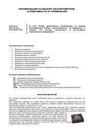
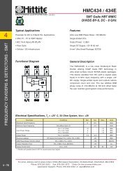
v00.0511<strong>HMC896LP4E</strong>FILTER - TUNABLE, BAND PASS SMT10 - 18 GHzFILTERS - TUNABLE - SMTTypical ApplicationsThe <strong>HMC896LP4E</strong> is ideal for:• Test & Measurement Equipment• Military RADAR & EW/ECM• SATCOM & Space• Industrial & Medical EquipmentFunctional DiagramFeaturesFast Tuning ResponseExcellent Wideband RejectionTunable low side/high side rejection “notch”Single Chip Replacementfor Mechanically Tuned Designs24 Lead 4x4 mm SMT PackageGeneral DescriptionThe <strong>HMC896LP4E</strong> is a MMIC band pass filter whichfeatures a user selectable passband frequency.The 3 dB filter bandwidth is approximately 9%. The20 dB filter bandwidth is approximately 22%. Thecenter frequency can be varied between 10 and 18GHz by applying an analog tune voltage between 0and 14V. This tunable filter can be used as a muchsmaller alternative to physically large switched filterbanks and cavity tuned filters. The <strong>HMC896LP4E</strong> hasexcellent microphonics due to the monolithic design,and provides a dynamically adjustable solution inadvanced communications applications.Electrical Specifications, T A= +25 °C, Vfctl = Vnctl Unless Otherwise StatedParameter Min. Typ. Max. UnitsF center Tuning Range 10 18 GHz3 dB Bandwidth 9 %Low Side Rejection Frequency (Rejection >20 dB) 0.89 *F center GHzHigh Side Rejection Frequency (Rejection >20 dB) 1.10 *F center GHzLow Side Sub-Harmonic Rejection (Rejection >40 dB) 0.75 *F center GHzHigh Side Sub-Harmonic Rejection (Rejection >40 dB) 1.18 *F center GHzRe-entry Frequency (Rejection 40 GHzInsertion Loss 9 dBReturn Loss (2 dB bandwidth) 11 dBInput IP3 (Pin = 0 to +15 dBm) 26 dBmInput Power @ 5° Shift In Insertion Phase (Vfctl = 0V) 8 dBmInput Power @ 5° Shift In Insertion Phase (Vfctl = 1V) 12 dBmFrequency Control Voltage (Vfctl) 0 14 VSource/Sink Current (Ifctl) ±1 mALow Side/High Side Rejection Control Voltage (Vnctl) 0 14 VSource/Sink current (Inctl) ±1 mAResidual Phase Noise [1] (100 kHz Offset) -158 dBc/HzF center Drift Rate -1.5 MHz/°CTuning Speed, Phase Settling to within 10° [2] < 200 ns[1] Optimum residual phase noise performance requires the use of a low noise driver circuit.[2] Tuning speed includes 40 ns tuning voltage ramp from driver.1For price, delivery and to place orders: <strong>Hittite</strong> <strong>Microwave</strong> Corporation, 2 Elizabeth Drive, Chelmsford, MA 01824Phone: 978-250-3343 Fax: 978-250-3373 Order On-line at www.hittite.comApplication Support: Phone: 978-250-3343 or apps@hittite.com
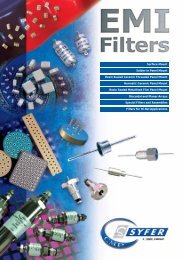
v00.0511<strong>HMC896LP4E</strong>FILTER - TUNABLE, BAND PASS SMT10 - 18 GHzBroadband Insertion Loss, Vfctl = Vnctl0Broadband Return Loss, Vfctl = Vnctl0INSERTION LOSS (dB)-10-20-30-40-50-60-700 5 10 15 20 25 30 35 40FREQUENCY (GHz)Insertion Loss, Vfctl = VnctlINSERTION LOSS (dB)0-2-4-6-8-10-12-14-16-18-200V3V7V14V0V3V7V14V-228 10 12 14 16 18 20 22FREQUENCY (GHz)RETURN LOSS (dB)-5-10-15-20-25-30-350 5 10 15 20 25 30 35 40FREQUENCY (GHz)Return Loss, Vfctl = VnctlRETURN LOSS (dB)0-5-10-15-20-25-30S11_0VS22_0VS11_7VS22_7VS11_14VS22_14VS11_0VS22_0VS11_7VS22_7VS11_14VS22_14V-358 10 12 14 16 18 20 22FREQUENCY (GHz)FILTERS - TUNABLE - SMTInsertion Loss vs. TemperatureVfctl = Vnctl = 7VINSERTION LOSS (dB)0-2-4-6-8-10-12-14-16-18-20+25C+85C-40C-2213 14 15 16 17 18 19FREQUENCY (GHz)Return Loss vs. TemperatureVfctl = Vnctl = 7VRETURN LOSS (dB)0-5-10-15-20-25-30-35+25C_S11+25C_S22+85C_S11+85C_S22-40C_S11-40C_S22-4013 14 15 16 17 18 19FREQUENCY (GHz)For price, delivery and to place orders: <strong>Hittite</strong> <strong>Microwave</strong> Corporation, 2 Elizabeth Drive, Chelmsford, MA 01824Phone: 978-250-3343 Fax: 978-250-3373 Order On-line at www.hittite.comApplication Support: Phone: 978-250-3343 or apps@hittite.com2
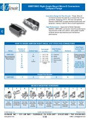
v00.0511<strong>HMC896LP4E</strong>FILTER - TUNABLE, BAND PASS SMT10 - 18 GHzLow Side Rejection Ratiovs. Temperature [1]0.95High Side Rejection Ratiovs. Temperature [1]1.2F20dB TO Fcenter RATIO0.90.850.8+25C+85C-40C0.750 2 4 6 8 10 12 14Vfctl = Vnctl (Vdc)Tuning Sensitivity vs. TemperatureSENSITIVITY (MHz/V)140012001000800600400200+25C+85C-40C01 2 3 4 5 6 7 8 9 10 11 12 13 14Vfctl = Vnctl (Vdc)F20dB To Fcenter RATIO1.151.11.05+25C+85C-40C10 2 4 6 8 10 12 14Vfctl = Vnctl (Vdc)Group Delay vs. FrequencyGROUP DELAY (ns)1.210.80.60.40V2V7V14V0.26 8 10 12 14 16 18 20 22 24FREQUENCY (GHz)FILTERS - TUNABLE - SMTGroup Delay vs. Fcenter vs. Temperature1Input IP3 vs. Temperature35GROUP DELAY (ns)0.90.80.70.6+ 25C+ 85C- 40CINPUT IP3 (dBm)302520+ 25C+ 85C- 40C0.50 2 4 6 8 10 12 14Vfctl = Vnctl (Vdc)150 2 4 6 8 10 12 14Vfctl = Vnctl (Vdc)[1] Rejection ratio is defined as the ratio of the frequency at which the relative insertion loss is 20 dB to ƒcenterFor price, delivery and to place orders: <strong>Hittite</strong> <strong>Microwave</strong> Corporation, 2 Elizabeth Drive, Chelmsford, MA 01824Phone: 978-250-3343 Fax: 978-250-3373 Order On-line at www.hittite.comApplication Support: Phone: 978-250-3343 or apps@hittite.com4
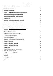
v00.0511<strong>HMC896LP4E</strong>FILTER - TUNABLE, BAND PASS SMT10 - 18 GHzFILTERS - TUNABLE - SMTResidual Phase Noise, Vfctl = VnctlRESIDUAL PHASE NOISE (dBc/Hz)Insertion Phase vs. Input PowerVfctl = VnctlPHASE (DEGREES)-120-130-140-150-160-17010 2 10 3 10 4 10 5 10 6 10 70-5-10-15-20-25-30-35-40OFFSET FREQUENCY (Hz)0V1V7V10V14V+ 1V+ 7V+ 14V-450 2 4 6 8 10 12 14 16 18 20INPUT POWER (dBm)Phase Sensitivity vs. VfctlAPPROXIMATE Fcenter (GHz)Fcenter vs. Input PowerVfctl = VnctlFREQUENCY (MHz)2019181716151413121110900 2 4 6 8 10 12 14Vfctl = Vnctl (Vdc)0-10-20-30-40-50-60-70-80-90-100-110-1200V1V7V10V14VApproximateFcenterDelta Phi-1300 2 4 6 8 10 12 14 16 18 20INPUT POWER (dBm)1110987654321DELTA PHI (RAD/V)Absolute Maximum RatingsFrequency Control Voltage (Vfctl) -0.5 to +15VNotch Control Voltage (Vnctl) -0.5 to +15VRF Power Input27 dBmStorage Temperature -65 to +150 °CESD Sensitivity (HBM)Class 1AReliability InformationJunction Temperature to Maintain1 Million Hour MTTFNominal Junction Temperature(T= 85 °C and Pin = 27 dBm)150 °C103 °COperating Temperature -40 to +85 °CELECTROSTATIC SENSITIVE DEVICEOBSERVE HANDLING PRECAUTIONS5For price, delivery and to place orders: <strong>Hittite</strong> <strong>Microwave</strong> Corporation, 2 Elizabeth Drive, Chelmsford, MA 01824Phone: 978-250-3343 Fax: 978-250-3373 Order On-line at www.hittite.comApplication Support: Phone: 978-250-3343 or apps@hittite.com
v00.0511<strong>HMC896LP4E</strong>FILTER - TUNABLE, BAND PASS SMT10 - 18 GHzOutline DrawingNOTES:1. LEADFRAME MATERIAL: COPPER ALLOY2. DIMENSIONS ARE IN INCHES [MILLIMETERS]3. LEAD SPACING TOLERANCE IS NON-CUMULATIVE.4. Pin BURR LENGTH SHALL BE 0.15 mm MAXIMUM.Pin BURR HEIGHT SHALL BE 0.05 mm MAXIMUM.5. PACKAGE WARP SHALL NOT EXCEED 0.05 mm.6. ALL GROUND LEADS AND GROUND PADDLE MUST BESOLDERED TO PCB RF GROUND.7. REFER TO HITTITE APPLICATION NOTE FOR SUGGESTEDLAND PATTERN.FILTERS - TUNABLE - SMTPackage InformationPart Number Package Body Material Lead Finish MSL Rating Package Marking [1][2] H896<strong>HMC896LP4E</strong> RoHS-compliant Low Stress Injection Molded Plastic 100% matte Sn MSL1XXXX[1] 4-Digit lot number XXXX[2] Max peak reflow temperature of 260 °CFor price, delivery and to place orders: <strong>Hittite</strong> <strong>Microwave</strong> Corporation, 2 Elizabeth Drive, Chelmsford, MA 01824Phone: 978-250-3343 Fax: 978-250-3373 Order On-line at www.hittite.comApplication Support: Phone: 978-250-3343 or apps@hittite.com6
v00.0511<strong>HMC896LP4E</strong>FILTER - TUNABLE, BAND PASS SMT10 - 18 GHzPin DescriptionsPin Number Function Description Interface SchematicFILTERS - TUNABLE - SMT1, 2, 4 - 7, 12 - 15,17 - 19, 24GND11, 20 - 23 NC3 RFINThese pins and exposed paddlemust be connected to RF/DC ground.The pins are not connected internally; however, all datashown herein was measured with these pins connected toRF/DC ground externallyThis pin is AC coupled andmatched to 50 Ohms.8 Vnctl Low side/high side notch control voltage.9 Vfctl Center frequency control voltage.10 Vfctl Center frequency control voltage.16 RFOUTThis pin is AC coupled andmatched to 50 Ohms.Application Circuit7For price, delivery and to place orders: <strong>Hittite</strong> <strong>Microwave</strong> Corporation, 2 Elizabeth Drive, Chelmsford, MA 01824Phone: 978-250-3343 Fax: 978-250-3373 Order On-line at www.hittite.comApplication Support: Phone: 978-250-3343 or apps@hittite.com
v00.0511<strong>HMC896LP4E</strong>FILTER - TUNABLE, BAND PASS SMT10 - 18 GHzEvaluation PCBFILTERS - TUNABLE - SMTList of Materials for Evaluation PCB 131085 [1]ItemDescriptionJ1, J2 Connector, 2.9mm, FemaleJ5,J6,J7, J8DC PinC1, C2, C3 100 pF Capacitor, 0402 Pkg.U1PCB [2]<strong>HMC896LP4E</strong> Filter - Tunable130746 Evaluation PCB[1] Reference this number when ordering complete evaluation PCB[2] Circuit Board Material: Arlon 25FR or Rogers 25FRThe circuit board used in the application should useRF circuit design techniques. Signal lines shouldhave 50 Ohms impedance while the packageground leads and exposed paddle should be connecteddirectly to the ground plane similar to thatshown. A sufficient number of via holes should beused to connect the top and bottom ground planes.The evaluation circuit board shown is available from<strong>Hittite</strong> upon request.For price, delivery and to place orders: <strong>Hittite</strong> <strong>Microwave</strong> Corporation, 2 Elizabeth Drive, Chelmsford, MA 01824Phone: 978-250-3343 Fax: 978-250-3373 Order On-line at www.hittite.comApplication Support: Phone: 978-250-3343 or apps@hittite.com8