

DESCRIPTION (5S–FE) - CelicaTech
DESCRIPTION (5S–FE) - CelicaTech
DESCRIPTION (5S–FE) - CelicaTech
- No tags were found...

Create successful ePaper yourself
Turn your PDF publications into a flip-book with our unique Google optimized e-Paper software.
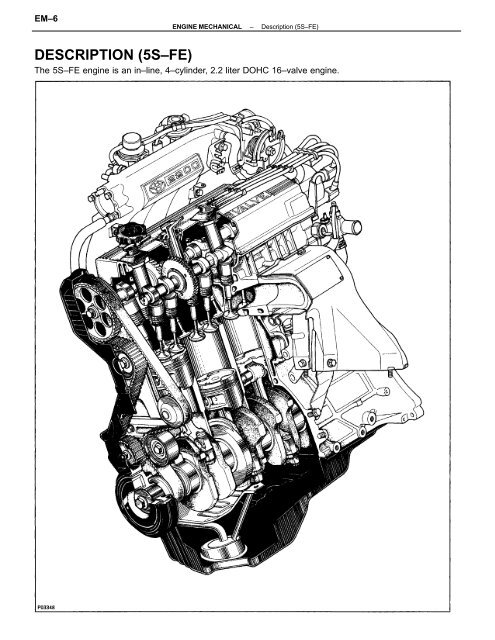
EM–6ENGINE MECHANICAL–Description (<strong>5S–FE</strong>)<strong>DESCRIPTION</strong> (<strong>5S–FE</strong>)The <strong>5S–FE</strong> engine is an in–line, 4–cylinder, 2.2 liter DOHC 16–valve engine.
ENGINE MECHANICAL–Description (<strong>5S–FE</strong>)EM–7The <strong>5S–FE</strong> engine is an in–line, 4–cylinder engine with the cylinders numbered 1 – 2 – 3 – 4 from thefront. The crankshaft is supported by 5 bearings inside the crankcase. These bearings are made of aluminumalloy.The crankshaft is integrated with 8 weights for balance. Oil holes are placed in the center of thecrankshaft to supply oil to the connecting rods, bearing, pistons and other components.The ignition order is ”I – 3 – 4 – 2. The cylinder head is made of aluminum alloy, with a cross flow typeintake and exhaust layout and with pent–roof type combustion chambers. The spark plugs are located inthe center of the combustion chambers.The intake manifold has 4 independent long ports and utilizes the inertial supercharging effect to improveengine torque at low and medium speeds.Exhaust and intake valves are equipped with irregular pitch springs made of special valve spring carbonsteel which are capable of functioning no matter what the engine speed.The intake camshaft is driven by a timing belt, and a gear on the intake camshaft engages with a gearon the exhaust camshaft to drive it. The cam journal is supported at 5 places between the valve lifters ofeach cylinder and on the front end of the cylinder head. Lubrication of the cam journals and gears isaccomplished by oil being supplied through the oiler port in the center of the camshaft.Adjustment of the valve clearance is done by means of an outer shim type system, in which valveadjusting shims are located above the valve lifters. This permits replacement of the shims without removalof the camshafts.Pistons are made of high temperature–resistant aluminum alloy, and a depression is built into the pistonhead to prevent interference with the valves.Piston pins are the full–floating type, with the pins fastened to neither the piston boss nor the connectingrods. Instead, snap rings are fitted on both ends of the pins, preventing the pins from falling out.The No.1 compression ring is made of steel and the No.2 compression ring is made of cast iron. The oilring is made of a combination of steel and stainless steel. The outer diameter of each piston ring is slightlylarger than the diameter of the piston and the flexibility of the rings allows them to hug the cylinder wallswhen they are mounted on the piston. Compression rings No.1 and No.2 work to prevent gas leakage fromthe cylinder and the oil ring works to scrape oil off the cylinder walls to prevent it from entering thecombustion chambers.The cylinder block is made of cast iron. It has 4 cylinders which are approximately twice the length ofthe piston stroke. The top of each cylinder is closed off by the cylinder head and the lower end of thecylinders becomes the crankcase, in which the crankshaft is installed. In addition, the cylinder blockcontains a water jacket, through which coolant is pumped to, cool the cylinders.The oil pan is bolted onto the bottom of the cylinder block. The oil pan is an oil reservoir made of pressedsteel sheet. A dividing plate is included inside the oil pan to keep sufficient oil in the bottom of the paneven when the vehicle is tilted. This dividing plate also prevents the oil from making waves when thevehicle is stopped suddenly and the oil shifts away from the oil pump suction pipe.


