General Purpose Three-Phase Induction Motors ... - Cantoni Group
General Purpose Three-Phase Induction Motors ... - Cantoni Group
General Purpose Three-Phase Induction Motors ... - Cantoni Group
- No tags were found...

You also want an ePaper? Increase the reach of your titles
YUMPU automatically turns print PDFs into web optimized ePapers that Google loves.
<strong>General</strong> <strong>Purpose</strong> 3-phase <strong>Induction</strong> <strong>Motors</strong>INTRODUCTIONNew efficiency classes for the low-voltage three-phase motors (IE = International Efficiency).Along with the international discussion on energy efficiency a worldwide harmonized energy efficiency classificationsystem has been established for low-voltage three-phase asynchronous motors.For many years low-voltage three-phase motors in the European Union have been sold in three efficiency classes EFF3,EFF2 and EFF1. Aside from this, many different efficiency classification systems have been introduced and well-proven inmany countries all over the world.This was the reason for the International Electrotechnical Commission IEC to develop and publish an energy efficiencystandard which replaces all previous national issues. In parallel IEC developed and issued a new standard for determiningmotor efficiency. The new standard IEC 60034-30 defines and harmonizes worldwide the efficiency classes IE1, IE2 and IE3for low-voltage three-phase motors in the power range from 0.75 kW to 375 kW (2p=2, 4, 6):IE1 = Standard EfficiencyIE2 = High EfficiencyIE3 = Premium EfficiencyFrom now motors can be offered and sold with the new classes IE1, IE2 and IE3.In that case the efficiency has to be determined according to the new requirements given in the IEC 60034-2-1 standard.According to the Comission Regulation (EC) No 640/2009 (introduced in July 2009) the required efficiency classof general-purpose motors (introduced to the market in future) will be as follows:From 16 June 2011, motors placed for the first-time on the market shall have a minimum efficiency class of IE2.From 1 January 2015: motors with a rated output between 7.5 - 375 kW shall have a minimum efficiency class of IE3,or IE2 if they are operated/equipped with electronic speed control (VSD).From 1 January 2017: motors with a rated output between 0.75 - 375 kW shall have a minimum efficiency class of IE3,or IE2 if they are operated/equipped with electronic speed control (VSD).Electronic speed control is carried out using a frequency converter (VSD) that adjusts thespeed of the motor - and therefore the torque produced - based on the energy needed.2010 20112015 2017IE2 (0,75 - 375kW)Change in the law from 16.06.2011.IE3 (7,5 - 375kW), IE2 (with VSD)IE3 (0,75 - 375kW), IE2 (with VSD)<strong>Cantoni</strong> <strong>Group</strong> IE1 motors<strong>Cantoni</strong> <strong>Group</strong> 2SIE motors (IE2)<strong>Cantoni</strong> <strong>Group</strong> has offered energy efficiency motors for several years.Our motors of SEE series fulfil EFF1 standards according to CEMEP.We carry out intensive research and measurement of the motors according to the new standardsIEC 60034-30 and IEC 60034-2-1.05
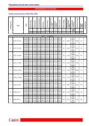
<strong>General</strong> <strong>Purpose</strong> 3-phase <strong>Induction</strong> <strong>Motors</strong>EFFICIENCY OF MOTORS<strong>Cantoni</strong> Motor has in offer general purpose standard efficiency motors of (2) Sg, Sh series which fulfil IE1class requirements according to the IEC 60034-30 standard.The present catalogue describes the electric motors which belong to the efficiency class IE2 (High Efficiency)and motors excluded from the IEC 60034-30 standard (motors with 2p = 8, 10, 12 and with rated output below0.75kW and above 375kW).Comparison between the efficiency of <strong>Cantoni</strong> <strong>Group</strong> motors (for example 2p=4)and efficiency class IE1/IE2 requirements according to the IEC 60034-30.94Efficiency [%]8678700,1 1 10 100 400P N [kW]IE2IE1High Efficiency (<strong>Cantoni</strong>)Standard (<strong>Cantoni</strong>)The efficiency class system specified under IEC 60034-30 is valid for low voltage three phasesquirrel cage induction motors with the following specifications:· Rated voltage up to 1.000 V· Rated output between 0.75 kW and 375 kW· Either 2, 4 or 6 poles· Rated on the basis of continuous duty (S1) or intermittent periodic duty (S3) withcyclic duration factor of 80% or higher· Capable of operating direct on-line· Rated for operating conditions in accordance with IEC 60034-1 (temperature,installation altitude, etc.)<strong>Motors</strong> with flanges, feet and/or shafts with mechanical dimensions different from IEC 60072-1are also covered by this standard.06
<strong>General</strong> <strong>Purpose</strong> 3-phase <strong>Induction</strong> <strong>Motors</strong>RATINGS - TOLERANCESPermissible deviations between real values and catalogue values according to the IEC 60034-1:Power factor cos cos= -1/6 (1- cos) NEfficiency = -15%(100- ) for P 150kWSpeed n= -10%(100-) N for PN150kWn = ±20%(n -n ) for P 1kWs N Nn = ±30%(n -n ) for P 1kWs N NLocked rotor current I /I (I /I ) = +20% (I /I )L N r N L NLocked rotor torque T /T min (T /T ) = -15% (T /T )L N L N L Nmax (T /T ) = +25% (T /T )L N L NBreakdown torque T B/TN (T B/T N) = -10% (T B/T N)Moment of inertia J [kgm 2]J = ±10% JSound pressure level L pA [dB] L pA = +3 dB /A/NNSTANDARDSThe electric motors are manufactured according to the international standards:Rating and performance IEC 60034-1Methods for determining losses and efficiency IEC 60034-2-1Classification of degrees of protection IEC 60034-5Methods of cooling IEC 60034-6Symbols of construction and mounting arrangements IEC 60034-7Terminal markings and direction of rotation IEC 60034-8Noise limits IEC 60034-9Dimensions and output of electric machines IEC 60072-1Vibration limits IEC 60034-14New IEC standards regarding efficiency classes (IEC60034-30) and efficiency measurements (IEC 60034-2-1)The resulting efficiency values differ from those obtained under the previousIEC 60034-2:1996 testing standard.It must be noted that the efficiency values are only comparable if they are obtainedusing the same measuring method.EU Regulation 640/2009Commission Regulation 640/2009, adapted on 22 July 2009, specifies therequirements regarding the ecodesign of electric motors and the use of electronicspeed control (VSD).IE1IE2IE3All the motors are manufactured inQuality Assurance System consistent with ISO 9001.ISO9001The motors covered by the present catalogue comply with the regulationsand standards effective in other countries, consistent with IEC standards.IECAll the motors described in the present catalogue are provided with CE mark.07
<strong>General</strong> <strong>Purpose</strong> 3-phase <strong>Induction</strong> <strong>Motors</strong>INSULATION CLASSIFICATIONThe insulation system of an electric motor is determined by a given insulationclass on the basis of its thermal resistance.This thermal resistance should be guaranteed by the entire set of electricinsulating materials used in the motor insulating system.Thermal resistance classification is related to the temperature of the hotspotin the insulation occurring during rated operating conditions of the electricmotor, allowing for the highest permissible rise in average temperature.This rise should be selected so that at the highest permissible ambienttemperature, the temperature of the hotspot in insulation will not exceed thevalue assigned to a given thermal resistance class.Symbols of thermal resistance classes(permissible insulation temperaturesat 40°C ambient temperature)Symbol Temperature [° C]A 105E 120B 130F 155H 180A40°60°5°Ambient temperatureMaximaltemperature riseTemperature marginInsulation class F in an electric motor means thatat ambient temperature of 40°C the temperaturerise of the winding may be max. 105°C with theadditional temperature margin of 10°C(under specified measuring conditions inaccordance with the IEC 60034-1 standard).Insulation classEBFH40°40°40°40°75°80°105°125°5°10°10°15°Class FThe standard motors made by <strong>Cantoni</strong> Motor intheir basic version have the insulation class F whilethe temperature rise is for class B.This means longer life for motors.For special request we can deliver motors equippedwith insulation class H.Strengthened insulation system gives possibilityto safe operation with converters.MOTOR FEET<strong>Motors</strong> with frame size 112 have screwed feet.<strong>Motors</strong> with frame size 132 have screwed feet or feet integrated with the motor housing.<strong>Motors</strong> with frame size160 and180 have feet integrated with the motor housing.<strong>Motors</strong> with frame size 180 up to 315 have feet integrated with the motor housing.<strong>Motors</strong> with frame size 315 have screwed feet or feet integrated with the motor housing.<strong>Motors</strong> with frame size 355 have feet integrated with the motor housing.TERMINAL BOXThe terminal boxes of low voltage motors have threaded inletholes designed for mounting cable glands.The box contains a terminal board with marked terminalsmaking possible connection of supply cables.In addition, terminal boxes may be provided with additionalterminals connected to the ends of thermal protection oranticondensation heater circuits and extra glands to connectthese circuits.Low voltage high-power motors contain terminal boxes withcable gland seals.The circuits of thermal protection and anticondensation heatersare connected to separate terminal boxes.Inside the boxes there are special clamps used to ground thesupply cable armouring.VIBRATION LEVEL AND NOISE LEVELThe rotor balancing method guarantees that a standard vibration level A is maintained in accordance withthe IEC 60034-14 and a standard sound power level is maintained in accordance with the IEC 60034-9.On customer’s demand the motors can be made with reduced vibration or noise level.level A08
<strong>General</strong> <strong>Purpose</strong> 3-phase <strong>Induction</strong> <strong>Motors</strong>INTERNATIONAL PROTECTION IPAccording to the IEC 60034-5 standard the electric motors areprovided with IP code which determines the degree of protection(ensured by the housing) against penetration of solid matter andfluids.IP55PROTECTION AGAINST PENETRATIONOF SOLID MATTERPROTECTION AGAINSTPENETRATION OF FLUIDSIKMECHANICAL PROTECTION1st digitDESCRIPTION2nd digitDESCRIPTION3rd digitDESCRIPTION00 No protection0Not protected0 Not protected1 Protected against verticallyfalling drops of water01150 g10 cmStriking energy:0.15 J1Protected againstsolid bodies larger than50 mmProtected against21515 vertically fallingdrops of water up to 15°02200 g10 cmStriking energy:0.20 J2Protected againstsolid bodieslarger than12 mm6060Protected against3 rain up to 60°03250 g15 cmStriking energy:0.37 JProtected against3 solid bodieslargerthan 2.5 mmProtected against4 rain falling from anydirection04250 g20 cmStriking energy:0.50 JProtected against4 solid bodieslargerthan1mm5Protected againstsprayed waterfrom any direction05350 g20 cmStriking energy:0.70 J5Protected againstdeposition of dustProtected against6 temporaryimmersion06250 g40 cmStriking energy:1 JTotally6 protected againstdeposition of dust7 Protected against immersionbetween 0.15 and 1 m8 Protected against immersion atpreset pressure and time070.5 kg40 cmStriking energy:2 JAll <strong>Cantoni</strong> <strong>Group</strong> standard motors are manufactured with IP 55 degree ofprotection according to the standard in force (IEC 60034-5). The followingtable lists its characteristics.081.25 kg40 cmStriking energy:5 JEach size 80 to 180 motor is equipped with seal rings on the control sideand on the opposite side. Labyrinth seals protect the motors from size 200and above.The terminal board box is sealed with a gasket.<strong>Motors</strong> with a higher degree of protection areavailable on request.09102.5 kg5 kg40 cm40 cmStriking energy:10 JStriking energy:20 J09
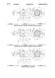
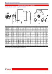
<strong>General</strong> <strong>Purpose</strong> 3-phase <strong>Induction</strong> <strong>Motors</strong>MOUNTING ARRANGEMENTSAccording to the IEC 60034-7 standardHorizontal shaftVertical shaftDesignationDesignationFrame sizeCode II Code I Code II Code IFrame sizeIM 1001 IM B3 56 ÷ 500 IM 1011 IM V5 56 ÷ 315without 2SIE 315 M6B,C,Dwithout SIE 315 M8C,DIM 1051 IM B6 56 ÷ 280 IM 1031 IM V6 56 ÷ 315without 2SIE 315 M6B,C,Dwithout SIE 315 M8C,DIM 1061 IM B7 56 ÷ 280 IM 2011 IM V15 56 ÷ 355or IM 2111IM 1071 IM B8 56 ÷ 280 IM 2031 IM V36 56 ÷ 355or IM 2131IM 2001 IM B35 56 ÷ 500 IM 3011 IM V1 56 ÷ 500IM 2101 IM B34 56 ÷ 132 IM 3031 IM V3 56 ÷ 28056 ÷ 315IM 3001 IM B5 without 2SIEK 315 M6B,C,D IM 3611 IM V18 56 ÷ 180without SIEK 315 M8C,DIM 3601 IM B14 56 ÷ 132 IM 3631 IM V19 56 ÷ 18010
<strong>General</strong> <strong>Purpose</strong> 3-phase <strong>Induction</strong> <strong>Motors</strong>PERMISSIBLE LOADS ON THE SHAFT ENDFrameNumber Horizontal Vertical Frame Number Horizontal Verticalsize of poles operation operation size of poles operation operationFRXFpFRXFpFa2Fa2XmaxX0XmaxX0Fa1Fa1F R(x = 0) F R(x = max) Fp Fa1 Fa2 F R(x = 0) F R(x = max) Fp Fa1 Fa2[kN] [kN] [kN] [kN]Sh 56 2 0,20 0,16 0,04 0,03 0,05Sh 56 4 0,25 0,20 0,05 0,04 0,06Sh 56 6 0,25 0,20 0,06 0,05 0,07Sh 63 2 0,20 0,16 0,04 0,04 0,06Sh 63 4 0,25 0,20 0,06 0,05 0,07Sh 63 6 0,27 0,22 0,06 0,05 0,07Sh 63 8 0,27 0,22 0,07 0,06 0,08Sh 71 2 0,29 0,24 0,07 0,05 0,09Sh 71 4 0,36 0,30 0,09 0,07 0,11Sh 71 6 0,40 0,35 0,10 0,08 0,12Sh 71 8 0,40 0,35 0,11 0,09 0,132SIE 80 (Sh) 2 0,33 0,27 0,09 0,06 0,122SIE 80 (Sh) 4 0,44 0,37 0,12 0,09 0,15Sh 80 6 0,51 0,42 0,14 0,11 0,17Sh 80 8 0,51 0,42 0,17 0,15 0,202SIE 90 2 0,68 0,44 0,68 0,35 0,382SIE 90 4 0,78 0,44 0,78 0,35 0,382SIE 90 6 0,96 0,44 0,96 0,35 0,382SIE 100 2 0,88 0,46 0,90 0,28 0,402SIE 100 4 1,06 0,46 0,98 0,38 0,402SIE 100 6 1,20 0,46 1,10 0,38 0,402SIE 112 2 1,00 0,48 1,00 0,40 0,452SIE 112 4 1,45 0,48 1,40 0,40 0,452SIE 112 6 1,62 0,48 1,60 0,40 0,452SIE 132 2 1,82 0,66 1,90 0,43 0,602SIE 132 4 2,10 0,66 2,20 0,45 0,602SIE 132 6 2,80 0,66 2,80 0,50 0,602SIE 160 2 2,22 0,98 2,30 0,92 0,952SIE 160 4 2,40 0,98 2,40 0,92 0,952SIE 160 6 2,85 1,10 2,90 0,98 1,002SIE 180 2 2,92 1,30 3,00 1,10 1,202SIE 180 4 3,60 1,30 3,60 1,10 1,302SIE 180 6 4,00 1,80 4,10 1,40 1,702SIE 200 LA 2 3,00 2,50 2,30 1,80 2,902SIE 200 LB 2 3,00 2,50 2,30 1,80 2,902SIE 200 L 4 3,70 3,10 2,80 2,00 3,902SIE 200 LA 6 4,30 3,60 3,60 2,90 4,602SIE 200 LB 6 4,20 3,50 3,60 2,80 4,602SIE 225 S 4 4,20 3,40 3,20 2,50 4,102SIE 225 M 2 3,30 2,80 2,50 1,90 3,302SIE 225 M 4 4,10 3,30 3,20 2,30 4,202SIE 225 M 6 4,70 3,80 4,00 3,00 5,302SIE 250 M 2 4,10 3,40 3,10 2,30 4,102SIE 250 M 4 5,20 4,30 3,90 2,90 5,202SIE 250 M 6 5,60 4,60 5,00 3,60 6,702SIE 280 S 2 3,90 3,30 3,10 2,00 4,402SIE 280 S 4 6,70 5,70 5,00 3,60 6,802SIE 280 S 6 7,70 6,60 5,80 4,20 7,702SIE 280 M 2 3,80 3,20 3,00 1,90 4,502SIE 280 M 4 6,50 5,50 4,90 3,40 6,902SIE 280 M 6 7,40 6,30 5,70 3,90 7,902SIE 315 S 2 3,60 3,10 3,00 1,60 4,702SIE 315 S 4 6,20 5,20 4,90 3,10 7,202SIE 315 S 6 7,00 5,90 5,60 3,80 7,802SIE 315 MA 2 3,30 2,80 2,90 1,40 4,802SIE 315 MB 2 2,90 2,50 2,80 1,10 5,002SIE 315 MA 4 5,80 4,80 4,70 2,70 7,302SIE 315 MB 4 5,40 4,50 4,60 2,40 7,502SIE 315 MA 6 6,20 5,20 5,30 2,70 8,702SIE 315 MB 6 5,60 4,80 5,20 2,00 9,202SIE 315 MC 2 2,80 2,50 2,70 0,60 5,402SIE 315 MC 4 6,30 5,30 4,30 1,10 8,502SIE 315 MC 6 7,50 6,30 5,10 1,80 9,202SIE 315 MD 6 7,50 6,30 5,00 1,80 9,20SIE 315 MC 8 9,40 8,00 6,50 3,90 10,10SIE 315 MD 8 9,20 7,90 5,80 3,00 9,50PERMISSIBLE LOADS ON THE SHAFT END for motors 2Sg (2p = 8 ÷ 12)F R(x = 0) F R(x = max) Fp Fa1 Fa2 F R(x = 0) F R(x = max) Fp Fa1 Fa2[kN] [kN] [kN] [kN]2Sg 200L8 8 5,10 4,20 4,10 3,40 5,002Sg 200L10A 10 5,50 4,60 4,20 3,50 5,102Sg 200L10B 10 5,50 4,50 4,10 3,40 5,102Sg 200L12 12 5,90 4,90 4,40 3,70 5,402Sg 225S8 8 5,90 4,70 4,70 3,90 5,702Sg 225S10 10 6,50 5,10 4,70 4,00 5,602Sg 225S12 12 6,70 5,30 4,80 4,20 6,002Sg 225M8 8 5,70 4,60 4,60 3,70 5,802Sg 225M10 10 6,30 4,90 5,70 4,40 7,402Sg 225M12 12 6,70 5,30 4,90 3,90 6,202Sg 250M8 8 6,90 5,60 5,60 4,30 7,202Sg 250M10 10 7,50 6,20 5,70 4,40 7,402Sg 250M12 12 8,10 6,70 6,10 4,80 7,802Sg 280S8 8 8,30 6,90 6,60 5,20 8,502Sg 280S10 10 9,30 7,70 6,70 5,40 8,402Sg 280S12 12 9,80 8,10 7,00 5,70 8,702Sg 280M8 8 8,00 6,60 6,50 4,90 8,602Sg 280M10 10 8,80 7,30 6,50 5,20 8,202Sg 280M12 12 9,20 7,60 6,80 5,00 9,302Sg 315S8 8 8,40 7,00 7,00 5,00 9,602Sg 315S10 10 9,30 7,70 7,60 5,60 10,202Sg 315S12 12 9,80 8,10 8,00 5,90 10,802Sg 315M8A 8 8,20 6,80 6,90 4,80 9,702Sg 315M8B 8 7,70 6,40 6,80 4,30 10,002Sg 315M10 10 8,40 7,00 7,30 4,80 10,702Sg 315M12A 12 9,30 7,70 7,90 5,50 11,102Sg 315M12B 12 9,10 7,60 7,80 5,30 11,2011
<strong>General</strong> <strong>Purpose</strong> 3-phase <strong>Induction</strong> <strong>Motors</strong>VERSION WITH ROLLER BEARINGS for motors 2SIE315 and 355Mechanical Size Type of construction No. of poles, 2p D.E. bearing N.D.E. bearing2SIE 315 ML IM1001 (B3) 4 ÷ 6 NU319 EM1C3 6314 C32SIE 355 ML IM1001 (B3) 4 ÷ 6 NU222 EM1C3 6222 C32SIE 355 H IM1001 (B3) 4 ÷ 6 NU322 EM1C3 6322 C3Horizontal mountingVertical operationPermissible radial forces Permissible axial forcesFX0 FXmax FAMotor type Number of poles Length of shaft extension E(mm) kN kN kN2SIE 315 ML 4 170 27 13 3,5 on request6 170 29 12 4 on request2SIE 355 ML 4 210 22 18 5 on request6 210 23 15 5,5 on request2SIE 355 H 4 210 27 17 6 on request6 210 29 15 7 on requestVERSION WITH ROLLER BEARINGS for motors SEE355 and Sh355-500Mechanical Size Type of construction No. of poles, 2p D.E. bearing N.D.E. bearingSEE 355 IM1001 (B3) 8 NU222 EM1C3 6222 C3Sh 355..s IM1001 (B3) 4 ÷ 8 NU322 EM1C3 6322 C3Sh 400..s IM1001 (B3) 4 ÷ 10 on request on requestSh 450..s IM1001 (B3) 4 ÷ 12 on request on requestSh 500..s IM1001 (B3) 4 ÷ 10 on request on requestHorizontal mountingPermissible radial forces Permissible axial forcesFX0 FXmax FAMotor type Number of poles Length of shaft extension E(mm) kN kN kNVertical operationSEE 355 8 210 24 14 6 on requestSh 355..s 4 210 27 17 6 on request8 210 30 15 8 on requestSh 400Sh 450 4 ÷ 8 on requestSh 500PERMISSIBLE LOADS ON THE SHAFT ENDValue of radial force F acting on the shaft end for aRgiven belt pulley diameter is calculated according tothe following formula:Value of force F acting on any point of the shaft endR(between points X=max and X=0) may be calculatedaccording to the following formula:where: P - motor output [kW]DK- belt pulley diameter [m]n - speed [rpm]k - belt tension factor:for V-belts k=2,2for flat belts k=3where: F X0 - value of F R force acting on the beginning of the shaft endF XMAX - value of F R force acting on the end of the shaft endE - lenght of the shaft end12
<strong>General</strong> <strong>Purpose</strong> 3-phase <strong>Induction</strong> <strong>Motors</strong>Other specifications dependent on the frame size:FramesizeDegree ofprotectionPosition ofthe terminalboxNumber ofterminalsNumber ofcable outletsOptionalrotation of theterminal boxGlandsTemperaturesensors inwindingBearinglubrication on therunThermalprotection ofbearings56 IP 55 top 6 1 180° M 20 on request no no63 IP 55 top 6 1 180° M 20 on request no no71 IP 55 top 6 1 180° M 20 on request no no80 IP 55 top 6 1 180° M 20 on request no no90 IP 55 top 6 2 180° M 20 on request no no100 IP 55 top 6 2 180° M 20 on request no no112 IP 55 top 6 2 180° M 25 on request no no132 IP 55 top 6 2 180° M 25 on request no no160 IP 55 top 6 2 180° M 40 on request on request on request180 IP 55 top 6 2 180° M 40 on request on request on request200 IP 55 top * 6 2 4 × 90° M 50 PTC yes on request225 IP 55 top * 6 2 4 × 90° M 50 PTC yes on request250 IP 55 top * 6 2 4 × 90° M 63 PTC yes on request280 IP 55 top * 6 2 4 × 90° M 63 PTC yes on request315 IP 55 top * 6 2 4 × 90° M 76 PTC yes on request355ML IP 55 top 6 2 4 × 90° M 76 PTC Mark A yes on request355H IP 55 top 6 2 4 × 90° M 90 Pt 100 yes Pt 100400 IP 55 top 6 (bars) 3 180° 3×55 Pt 100 yes Pt 100450 IP 55 top 3 (bars) 3 180° 3×55 Pt 100 yes Pt 100500 IP 55 top 3 (bars) 3 180° 3×55 Pt 100 yes Pt 100* right position of the terminal box for 2Sg motors seriesFrame Number Bearingssizeof polesSh 56 2 ÷ 6 6201 2ZSh 63 2 ÷ 8 6202 2ZSh 71 2 ÷ 8 6203 2Z2SIE 80 2 ÷ 6 6204 2Z2SIE 90 2 ÷ 6 6205 2Z C32SIE 100 2 ÷ 6 6206 2Z C32SIE 112 2 ÷ 6 6306 2Z C32SIE 132 2 ÷ 6 6308 2Z C32SIE 160 2 ÷ 6 6309 2Z C32SIE 180 2 ÷ 6 6311 2Z C32SIE 200 2 ÷ 6 6312 C32SIE 225 2 ÷ 6 6313 C32SIE 250 2 ÷ 6 6315 C32SIE 280 2 6315 C32SIE 280 4 ÷ 6 6318 C32SIE 315S,MA, MB 2 6315 C32SIE 315MC 2 6316 C32SIE 315S,MA, MB 4 ÷ 6 6318 C32SIE 315MC, MD 4 ÷ 6 6320C3/6318C3SIE 315MC, MD 8 6320C3/6318C3BEARINGS for 2Sg (2p = 8 ÷ 12)Frame Number Bearingssizeof poles2Sg 200 2 ÷ 12 6312 C32Sg 225 2 ÷ 12 6313 C32Sg 250 2 ÷ 12 6315 C32Sg 280 4 ÷ 12 6317 C32Sg 315 4 ÷ 12 6318 C3The bearings in basic version of motors for horizontal and verical duty,excluding 2SIE 315 with 2p=2.Frame Type of No. of D.E. N.D.E.Size construction poles, 2p bearing bearing2SIE 315 ML IM1001 (B3) 4 ÷ 6 6319 C3 6314 C32SIEL 315 ML IM2001 (B35) 4 ÷ 6 6319 C3 6314 C32SIE 355 ML IM1001 (B3) 2 6217 C3 6217 C32SIEL 355 ML IM2001 (B35) 4 ÷ 6 6222 C3 6222 C32SIEK 355 ML IM3011 (V1) 4 ÷ 6 6322 C3 6322 C32SIE 355 H IM1001 (B3) 2 6217 C3 6217 C32SIEL 355 H IM2001 (B35) 4 ÷ 6 6322 C3 6322 C32SIEK 355 H IM3011 (V1) 4 ÷ 6 6322 C3 6322 C3Frame Type of No. of D.E. N.D.E.Size construction poles, 2p bearing bearingSEE 355 IM1001 (B3) 8 6222 C3 6222 C3SLEE 355 IM2001 (B35) 8 6222 C3 6222 C3SVEE 355 IM3011 (V1) 8 6322 C3 6322 C3Sh 355..s IM1001 (B3) 2 6217 C3 6217 C3SLh 355..s IM2001 (B35) 4 ÷ 8 6322 C3 6322 C3SVh 355..s IM3001 (V1) 4 ÷ 8 6322 C3 6322 C3Sh 400..s IM1001 (B3) 2SLh 400..s IM2001 (B35) 4 ÷ 10SVh 400..s IM3011 (V1) 4 ÷ 10Sh 450..s IM1001 (B3) 4 ÷ 12SLh 450..s IM2001 (B35) 4 ÷ 12 on requestSVh 450..s IM3011 (V1) 4 ÷ 12Sh 500..s IM1001 (B3) 4 ÷ 10SLh 500..s IM2001 (B35) 4 ÷ 10SVh 500..s IM3011 (V1) 4 ÷ 10BEARINGSThe bearings in basicversion of motorsfor horizontal and verical duty.13
<strong>General</strong> <strong>Purpose</strong> 3-phase <strong>Induction</strong> <strong>Motors</strong>HOUSING, END SHIELDS, FEETFrameMotorEndsize [mm] housing shieldsFeet56 Aluminium Aluminium Aluminium - screwed63 Aluminium Aluminium Aluminium - screwed71 Aluminium Aluminium Aluminium - screwed80 Aluminium Aluminium Aluminium - screwed90 Aluminium Aluminium Aluminium - screwed100 Aluminium Aluminium Aluminium - screwed112 Aluminium Cast iron Aluminium - screwed132 Cast iron Cast iron Cast iron - screwed160 Cast iron Cast iron Cast iron - integrated180 Cast iron Cast iron Cast iron - integrated200 Cast iron Cast iron Cast iron - integrated225 Cast iron Cast iron Cast iron - integrated250 Cast iron Cast iron Cast iron - integrated280 Cast iron Cast iron Cast iron - integrated315 Cast iron Cast iron Cast iron - screwed or integrated355 Cast iron Cast iron Cast iron - integrated400 Cast iron Cast iron Cast iron - integrated450 Cast iron Cast iron Cast iron - integrated500 Cast iron Cast iron Cast iron - integratedIn motors series Sh, Sg of frame size 80, 90 and 100mm: on request end shields may be made of cast iron.In motors series 2SIE of frame size 80 and 90mm: on request end shields may be made of cast iron.In motors of frame size 132: feet may be integrated with housing.Motor housingaluminiumaluminiumcast iron80 90 100 112cast iron132 160 180 200 225 250 280 315 355400 450 50014
<strong>General</strong> <strong>Purpose</strong> 3-phase <strong>Induction</strong> <strong>Motors</strong>DESCRIPTION OF THE CATALOGUE VERSION2SIE 315 M 4 B(2)Sg, Sh, SEE 315 M 8 BA=Lower powerB=Higher powerC,D=Increased PowerFramelengthL=longM=mediumS=shortNo. of poles(Speed)Shaft h(in B3)2SIE2SIEK2SIEL(2)Sg, Sh, SEE (2)SKg, SKh, SVEE, SVh (2)SLg, SLh, SLEEORDERING INFORMATIONOrders for motors should specify:motor type designation,rated output,rated speed,operating duty,supply voltage and connection,frequency,mounting arrangements, end shield material,degree of protection,type of machine driven,other details of regarding special requests,When ordering high-power or special purpose motors oneshould also indicate:required direction of rotation,required degree of interior protection,method of start-up,method of coupling with the driven unit (gears,dimensions of belt pulleys, etc.),type of machine driven (nature of load), including the2moment of inertia J or flywheel effect GD brought to themotor shaft,other customer’s specifications.When ordering spare parts one should specify:and information concerning additional accessories e.g.thermal protection,anticondensation heaters,vibration sensors,etc.full designation of the motor type including its serialnumber (provided on the nameplate) or catalogue number,degree of protection,mounting arrangement,name of part,number of pieces.As part of our development program, we reserve the rightto alter or amend any of the specifications without giving prior notice15