ECIO2 Multi I/O compact module, Ethernet
ECIO2 Multi I/O compact module, Ethernet ECIO2 Multi I/O compact module, Ethernet
- Page 2 and 3: 1Technical dataSupply voltage 12 V
- Page 4: Galvanical separationFor three-wire
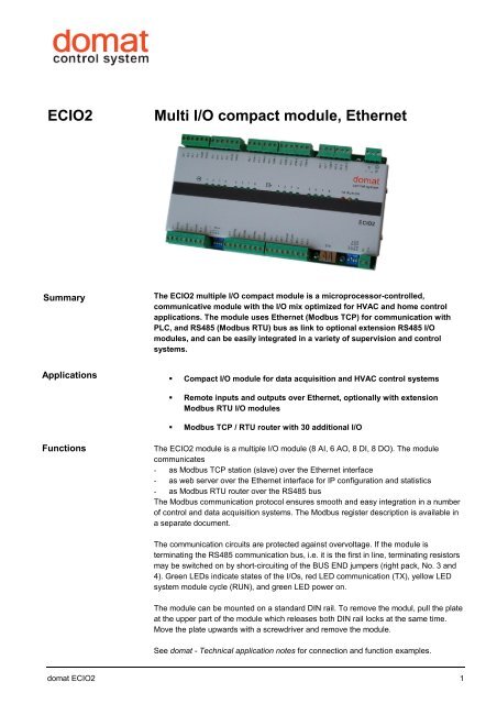
1Technical dataSupply voltage 12 V ÷ 24 V AC/DC, +/- 10 %ConsumptionWorking temperature of the<strong>module</strong>Communicationmax. 7.5 VA0 ÷ 60°C, non-condensingRS485, 1200 ... 19200 bit/s (Modbus RTU)<strong>Ethernet</strong>, 10/100 Mbps, RJ45 (Modbus TCP, HTTP)RS485 propertiesMax. bus lengthMax. number of <strong>module</strong>s on thebusAnalog InputsAnalog OutputsAnalog output loadDigital Inputs1200mup to 256 addresses; the maximum number of <strong>module</strong>sdepends on requested response time: for common HVACapplications, use max. 20 MCIO28x 0-10 V DC, measured ranges: Pt 1000, Pt100, Ni1000,resistance 20..1600 Ohm, 20...5000 Ohm, optional switchon125 Ohm resistor for (0) 4...20 mA at AI1 to AI416 bit resolution6x 0-10 V DC2x common terminal AOGNDgalvanically separated 1 kV from the rest of the <strong>module</strong>10 bit resolutionoutput impedance < 16 Ohmmin. 10kOhm, max. current 50mA,short-circuit-proof outputs – current limitation to 80 mA8x 24V AC/DC – input current 4 mA, voltage must beapplied e.g. from <strong>module</strong> powering terminals (no drycontacts)log. 0 ... U < 8 V AC/DClog. 1 ... U > 20 V AC/DCDigital OutputsDimensions6x relay, NO: 3A/250VAC, 3A/30VDC, 750VA, 90W2x relay, change-over: 8A/250VAC, 8A/24VDC, 2000VA,192W217 x 115 x 40 mm (incl. terminals)CE markingTerminalsDI1DI2DI3DI4DGNDDGNDDI5DI6DI7DI8DGNDDGNDNO1COM1NO2COM2NO3COM3NO4COM4NO5COM5NO6COM6NO7NC7COM7NO8NC8COM812TEDI1 DI2DI3 DI4DI5 DI6DI7 DI8DO1DO2DO3 DO4 DO5 DO6 DO7DO8<strong>ECIO2</strong>AI1AI2AI3AI4AI5AI6AI7AI8AO1 AO2AO3AO4 AO5 AO6AIA I GNDAI2A I GNDAI3A I GNDAI4A I GND0...20 mAAI1AI2AI3AI4AI5A I GNDAI6A I GNDAI7A I GNDAI8A I GNDAO1AO2AO3AOGNDAOGNDAO4AO5AO6ETHINITINIT ETHBUS ENDBUS ENDK1-K1DIP přepínač vedle svorek K1+, K1-2 domat <strong>ECIO2</strong>
~2BUSENDTx485K1+POWER~2BUSENDTx485K1+SwitchesDIP switch left:To use AI1...AI4 as 0(4)...20 mA set the corresponding switch 1...4 to ON.DIP switch right:1: INIT - if ON before power-up the I/O <strong>module</strong> is in the INIT mode - address 2,communication speed 9600 bps, 8, N, 12: INIT ETH – if ON before power-up the <strong>Ethernet</strong> communication part is in the INITmode – IP address is 192.168.1.993, 4: BUS END - if ON the bus is terminated, if OFF the bus is not terminated.LEDsInput and output states are indicated by green LEDs at the front panel.Status LEDs have following function:LED colour functionTX red blinking – <strong>module</strong> is transmitting at RS495RUN yellow blinking – <strong>module</strong> OK, on or off – <strong>module</strong> not workingON green on – power OK, off – no power or power supply damagedAddressingThe Modbus address is fixed and set to 2. All I/O point parameters (AI ranges, relaycomm fail states etc.) can be set through domat.exe, a configuration software which isfree to dowload at www.rcware.eu. Default communication parameters are 9600, 8, N,1. Use the TCP Gate function and locate the ECIO <strong>module</strong> at Modbus address 2. Ofcourse, all <strong>module</strong>s connected to the RS485 interface can be accessed and configuredover the <strong>Ethernet</strong> / RS485 Modbus routing function.Change the IP address and other network properties by accessing the <strong>module</strong> over aweb browser at its IP address.The default IP settings are:IP address 192.168.1.99subnet mask 255.255.255.0default gateway 192.168.1.1It is recommended to note the IP address on the <strong>module</strong> label.Modbus routingIt is possible to use <strong>ECIO2</strong> as a Modbus TCP/RTU router. Attach other <strong>module</strong>s to theRS485 interface; the <strong>ECIO2</strong> will be routing their Modbus RTU telegrams so that the<strong>module</strong>s are accessible over the <strong>Ethernet</strong> interface (Modbus TCP). This is how islandsof remote I/O <strong>module</strong>s may be created. Note that the I/O functionality depends on thecorrect functionality of the <strong>Ethernet</strong> network.Analogue input grounds (AIGND), analogue output grounds (AOGND), power source(terminals 1 and 2), digital inputs and digital outputs are separated from each other. This1increases EMC significantly and prevents from damaging the <strong>module</strong> by overvoltage.=TE1 = TEI NITAI1AI2AI3AI4INITINIT ETHBUS ENDBUS ENDK1-K1-POWERI NITIPLC5xx / IPCT.1 <strong>ECIO2</strong> Addr. 2 (fixed) e.g. M420 Addr. 3 M420 Addr. 4 ...domat <strong>ECIO2</strong> 3
Galvanical separationFor three-wire (power, ground, signal) connection of active output peripherials, such asvalves and damper actuators, define power ground (G0), e.g. terminal 2, and connect itto AOGND analogue outputs ground.For three-wire connection of active input peripherials (pressure, air quality, and humiditysensors etc. ) define power ground (G0), e.g. terminal 2, and connect it to AIGNDanalogue inputs ground.Digital inputs (DI) are optically separated from all other parts of the <strong>module</strong>, however,they all have common ground DGND (see image).All digital outputs (DO) are based on relays and thus galvanically separated from allother parts of the <strong>module</strong> as well as from each other.The communication part is optically separated from all other parts of the <strong>module</strong>.It is possible to use the same transformer for powering of <strong>module</strong>s and peripherials.The TE terminal may be connected to the ground potential (PES, shielding terminal).Compatibility withMCIOWhen changing MCIO for <strong>ECIO2</strong> please note the following:- hardware I/O signals are 100% compatible except for relay load of 3 A instead of5 A- it may be necessary to connect the AGND and AOGND terminals if active sensorsare used!- <strong>ECIO2</strong> is about 20 mm shorter, the terminals are located +/- 15...20 mm in the sameposition- it is necessary to rewire the connectors, the new <strong>module</strong> has connectors headingup and thus better fixed in the sockets- mind the RS485 connector polarity, K+ is on the right- the <strong>ECIO2</strong> contains one extra analog output- the <strong>module</strong> communicates with a process station over <strong>Ethernet</strong> rather than RS485- it is necessary to change the application software (use a Modbus / TCPchannel, insert new MCIO2 <strong>module</strong>, delete the MCIO and reconnect inputs andoutputs), because old and new <strong>module</strong>s have different Modbus maps! Use IDE0.9.10.0805 and later, available at www.rcware.eu.Related productsM...IPLC500, 510IPCT.1IPCB.1MCIO2I/O <strong>module</strong>sMiniPLC process stationsProcess station with touchscreenProcess station, no displayCompact I/O <strong>module</strong>, Modbus RTU09/2010 Subject to technical changes.4 domat <strong>ECIO2</strong>


