Installation Guide - raytec.ro
Installation Guide - raytec.ro
Installation Guide - raytec.ro
- No tags were found...

You also want an ePaper? Increase the reach of your titles
YUMPU automatically turns print PDFs into web optimized ePapers that Google loves.
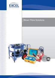
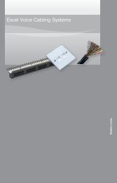
Technical Drawings (Not to scale)Standard Bracketry100mm(4”)12.5mm(0.5”)47mm(1.9”)25mm(1”)RM/RL 2536mm(1.4”)RM/RL 200/100/5072mm(2.8”)52mm(2”)33mm(1.2”)RM/RL 300/150Optional BracketryWall MountPtz MountDome MountPole Mount5
PSU SpecificationsInfra-Red Series PSURM300 RM200 RM150 RM100 RM50 RM25InputAC 100-230universal
Low Voltage PSU (LVP) SpecificationInfra-Red and WHITE-LIGHT Series PSU(Excluding Platinum and Covert Series)300 200 150 100 50 25Input x 24V AC/DC x 24V AC/DC 12/24V AC/DC 12/24V AC/DCFuse x 5A x 5A 3A 3ATypical Output(Infra-Red)Typical Output(White-Light)AdjustablePowerx 4.4A @ 13.5V x 2.4A @ 13.5V 1A @ 13.5V 0.5A @ 13.5Vx 4.2A @ 13.5V x 2.8A @ 13.5V 1.4A @ 13.5V 0.7A @ 13.5Vx 10% - 100% x 10% - 100% 10% - 100% 10% - 100%Weightx1.85 kg(4.1lbs)x1.65 kg(3.6lbs)0.9 kg(2lbs)0.8 kg(1.8lbs)DimensionsL x W x Dx160 x 160 x 81mm(6.3 x 6.3 x 3.2”)x160 x 160 x 81mm(6.3 x 6.3 x 3.2”)130 x 130 x 60mm 130 x 130 x 60mm(5.1 x 5.1 x 2.4”) (5.1 x 5.1 x 2.4”)DrillingDimensionsx4 x M4 holes@ 145 x 123mm(5.7” x 4.8”)x4 x M4 holes@ 145 x 123mm(5.7” x 4.8”)4 x M4 holes@ 113 x 113mm(4.4” x 4.4”)4 x M4 holes@ 113 x 113mm(4.4” x 4.4”)!NOTE: Ensure operating voltage is correct for unit being installed.DO NOT INPUT MAINS VOLTAGE INTO LOW VOLTAGE PSUs.Power Supply FeaturesStandard PSU• Adjustable photocell• Adjustable power• Telemetry inputPulsed PSU - PU• Analogue version• TTL version• No photocell• Adjustable power• 12V DC output @ 0.5A• Synch<strong>ro</strong>nised with cameraPREMIUM PSU-PR• Adjustable photocell• Adjustable power• Telemetry input• Photocell following contact, voltfree relay contact - normally open(day) to normally closed (night)• 12V DC output @ 0.5APremium Timer PSU-PRT• Adjustable photocell• Adjustable power• Telemetry input• Photocell following contact, voltfree relay contact - normally open(day) to normally closed (night)• 12V DC output @ 0.5A• Timer function7
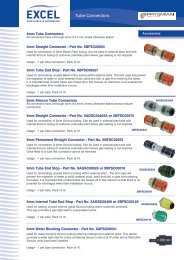
Power Supply Diagrams (Not to scale)Infra-Red and White-LightRM/RL 50/25 Models(Not to scale)PhotocellPower AdjustTelemetry Input- requires ze<strong>ro</strong> volt,latched inputPhotocell SensitivityLED Output x2(Polarity Sensitive)Mains Input100V to 230V ACAuto-SensingInfra-Red and White-LightRM/RL 200/100 Models (Model shown: RM/RL 100 Premium)(Not to scale)12V DC powe<strong>ro</strong>utput(Premium PSU only)Photocell followingcontact - volt free,non polarity sensitive(Premium PSU only)Telemetry Input- requires ze<strong>ro</strong> volt,latched inputPhotocellPower AdjustPhotocell SensitivityLED Output x2(Polarity Sensitive)Mains Input100V to 230V ACAuto-Sensing8
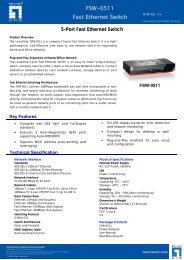
Infra-Red and White-LightRM/RL 300/150 and Hybrid Models(Final specification model dependant - model shown: RM/RL 300 Premium)Note - Hybrid cont<strong>ro</strong>l boards will be labelled IR/WLPhotocellfollowing contact- volt free, nonpolarity sensitive(Premium PSU only)Telemetry Inputrequires ze<strong>ro</strong> volt,latched inputPhotocellSensitivityPhotocell12V DC PowerOutput (PremiumPSU only)Power AdjustUp to x3LED Output(Polarity Sensitive)(Model Dependant)Mains Input(100V to 230V AC)Auto-Sensing9
T<strong>ro</strong>uble ShootingEnsure all tests are undertaken by a qualified, trained engineer.Ensure safe working practices are followed at all timesStep 1: Basics• Check polarity of Infra Red Lamp connectionred=+ve, black=-ve• Check telemetry link is in• Check photocell is working• Check power setting pot fully clockwise• Check mains input• Check fuse intactIf OK…Step 2: Lamp TestCheck voltage of lamp o/p app<strong>ro</strong>x 14V (8V for pulsed units)Check current of lamp – see instructions for correct current settingTo check lamp current (this must be done while both LED panelsare connected to the PSU) remove +ve LED f<strong>ro</strong>m both lamp supplycables and connect multimeter set to 10A current in line with thelamp. [One lead of multimeter in common (COM), other lead into10A socket of multimeter; set multimeter to 10A readings]. Refer toPSU Specifications for correct current settings, see pages 6-7.10
Step 3: Set-up Camera, lens and illuminationCheck alignment of lampCheck camera lens – fully open at night & set correctlyCheck model number to Raytec performance specification to ensurerequired distance is achievableStep 4: Call Raytec for further assistanceNote down:• Model and serial number of illuminator• Camera make and model• Lens make and modelIf the Raytec lamp is still not delivering the required performance,please contact us for further assistance.11
UK / Eu<strong>ro</strong>peT: +44 (0) 1670 520055F: +44 (0) 1670 819760sales@<st<strong>ro</strong>ng>raytec</st<strong>ro</strong>ng>cctv.comAmericas (Toll Free)T: +1 888 505 8335ussales@<st<strong>ro</strong>ng>raytec</st<strong>ro</strong>ng>cctv.comwww.<st<strong>ro</strong>ng>raytec</st<strong>ro</strong>ng>cctv.com