TABULAR DATA SHEET - UPGNet
TABULAR DATA SHEET - UPGNet
TABULAR DATA SHEET - UPGNet
- No tags were found...

Create successful ePaper yourself
Turn your PDF publications into a flip-book with our unique Google optimized e-Paper software.
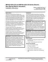
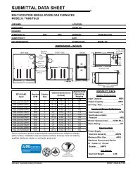
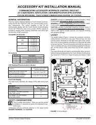
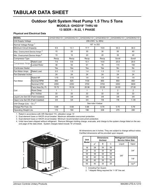
<strong>TABULAR</strong> <strong>DATA</strong> <strong>SHEET</strong>Physical and Electrical DataOutdoor Split System Heat Pump 1.5 Thru 5 TonsMODELS: GHGD18* THRU 6013 SEER – R-22, 1 PHASEMODELGHGD18S21S1 GHGD24S21S1 GHGD30S21S1 GHGD36S21S1 GHGD48S21S1 GHGD60S21S1Unit Supply Voltage208-230V, 1 60HzNormal Voltage Range 1 187 to 252Minimum Circuit Ampacity 9.9 13.1 17.7 19.8 30.3 38.3Max. Overcurrent Device Amps 2 15 20 30 30 50 60Min. Overcurrent Device Amps 3 15 15 20 20 35 40Compressor Type Recip Recip Recip Recip Scroll ScrollCompressor AmpsRated Load 7.6 9.9 13.1 14.6 23.0 29.5Locked Rotor 36 54 61 78 115 150Crankcase Heater Yes Yes Yes Yes No NoFan Motor Amps Rated Load 0.5 1.5 1.4 1.5 1.5 1.5Fan Diameter Inches 24 24 24 24 24 24Fan MotorRated HP 1/15 1/10 1/4 1/4 1/4 1/4Nominal RPM 850 825 1100 850 850 850Nominal CFM 2050 2250 3700 3700 3450 3600Face Area Sq. Ft. 15.72 18.34 20.96 23.58 24.00 27.00CoilRows Deep 1 1 1 1 2 2Fin / Inches 22 22 22 22 22 22Liquid Line Set OD (Field Installed) 3/8 3/8 3/8 3/8 3/8 3/8Vapor Line Set OD (Field Installed) 3/4 3/4 3/4 7/8 7/8 1-1/8Unit Charge (Lbs. - Oz.) 4See note 4 belowCharge Per Foot, Oz. 0.68 0.68 0.68 0.70 0.70 0.76Operating Weight Lbs. 172 184 196 208 275 2801. Rated in accordance with ARI Standard 110, utilization range “A”.2. Dual element fuses or HACR circuit breaker. Maximum allowable overcurrent protection.3. Dual element fuses or HACR circuit breaker. Minimum recommended overcurrent protection.4. Units have been shipped without refrigerant. Remove Nitrogen holding charge, evacuate, and charge to the system charge listed on the secondpage of the data sheet. System charges listed include 15' of lineset.ACAll dimensions are in inches. They are subject to change without notice.Certified dimensions will be provided upon request..UnitModelDimensions(Inches)Refrigerant ConnectionService Valve SizeA 1 B C Liquid Vapor18 28 34 3424 32 34 343/4”30 36 34 343/8”36 40 34 347/8”48 40 34 3460 40 34 34 7/8” 2B1. Including Fan Guard.2. * Adapter fitting required for 1-1/8” line set.Johnson Controls Unitary Products664285-UTD-A-1210
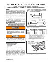
664285-UTD-A-1210System Charge for Various Matched SystemsOutdoor Unit GHGD18S21S1 GHGD24S21S1 GHGD30S21S1 GHGD36S21S1 GHGD48S21S1 GHGD60S21S1Required Orifice or TXV 1,2 2A 2A 2A 2A 2C 2CUnits have been shipped without refrigerant. Remove Nitrogen holding charge, select ID coil, select orifice or TXV, evacuate, andcharge to the system charge listed below for matching ID coil. System charges listed include 15' of lineset.Indoor Coil 3,4System Charge, (lbs - oz)AHP18 2A + (7 - 3) – – – – –AHP24 2A + (7 - 3) 2A + (7 - 7) – – – –AHP30 – 2A + (7 - 12) 2A + (8 - 12) – – –AHP36 – – 2A + (8 - 12) 2A + (9 - 1) – –AHP42 – – – 2A + (9 - 1) – –AHP48 – – – – 2C + (13 - 4) –AHP60 – – – 2A + (9 - 6) 2C + (13 - 4) –AHX18 2A + (7 - 3) – – – – –AHX24 2A + (7 - 3) 2A + (7 - 7) – – – –AHX30 – 2A + (7 - 7) 2A + (8 - 12) – – –AHX36 – – 2A + (8 - 12) 2A + (9 - 1) – –AHX42 – – – 2A + (9 - 1) – –AHX48 – – – – 2C + (13 - 4) –AHX60 – – – – – 2C + (15 - 5)AV24 2A + (7 - 3) 2A + (7 - 7) – – – –AV36 – – 2A + (8 - 12) 2A + (9 - 1) – –AV48 – – – 2A + (9 - 6) 2C + (13 - 4) –AV60 – – – – 2C + (13 - 4) –FC/MC/PC/UC18 2A + (7 - 3) – – – – –FC/MC/PC/UC24 2A + (7 - 3) 2A + (7 - 7) – – – –FC/MC/PC/UC30 2A + (7 - 3) 2A + (7 - 7) – – – –FC/MC/PC32 – 2A + (7 - 7) 2A + (8 - 12) – – –FC/MC/PC35 – 2A + (7 - 7) 2A + (8 - 12) – – –FC/MC/PCC37 – – 2A + (8 - 12) 2A + (9 - 1) – –FC/MC/PC43 – – 2A + (8 - 12) 2A + (9 - 1) – –FC/MC/PC/UC48 – – – 2A + (9 - 1) – –FC/MC/PC/UC60 – – – – 2C + (13 - 4) –FC/PC62D3X – – – – 2C + (13 - 6) 2C + (15 - 5)HC18 2A + (7 - 3) – – – – –HC30 – 2A + (7 - 7) – – – –HC36 – 2A + (7 - 2) 2A + (8 - 12) – – –HC42 – – 2A + (8 - 12) 2A + (9 - 1) – –HC60 – – – – 2C + (13 - 4) –HD24 – 2A + (7 - 11) – – – –HD36 – – 2A + (8 - 12) – – –HD48 – – – 2A + (9 - 4) – –HD60 – – – – 2C + (13 - 4) –F4FP024 2A + (7 - 3) – – – – –F4FP030 – 2A + (7 - 7) – – – –F4FP040 – – 2A + (8 - 12) – – –F5FP045 – – – 2A + (9 - 6) – –F5FP048 – – – 2A + (9 - 4) – –2 Johnson Controls Unitary Products
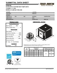
664285-UTD-A-1210System Charge for Various Matched Systems (Continued)Outdoor Unit GHGD18S21S1 GHGD24S21S1 GHGD30S21S1 GHGD36S21S1 GHGD48S21S1 GHGD60S21S1Required Orifice or TXV 1,2 2A 2A 2A 2A 2C 2CUnits have been shipped without refrigerant. Remove Nitrogen holding charge, select ID coil, select orifice or TXV, evacuate, andcharge to the system charge listed below for matching ID coil. System charges listed include 15' of lineset.Indoor Coil 3,4System Charge, (lbs - oz)F5FP060 – – – 2A + (9 - 6) 2C + (13 - 4) –F4FV060 – – – – 2C + (13 - 4) –F6FP018 .053 / 2A + (7- 3) – – – – –F6FP024 .053 / 2A + (7- 3) .059 / 2A + (7- 7) – – – –F6FP030 – .059 / 2A + (7-7) .065 / 2A + (8-12) – – –F6FP036 – .059 / 2A + (7-7) .065 / 2A + (8-12) .071 / 2A + (9-1) – –F6FP042 – – – .071 / 2A + (9-1) – –F6FP048 – – – – .084 / 2C + (13-4) –F6FP060 – – – – – 2C + (15 - 5)MH24 – 2A + (7 - 7) 2A + (8 - 12) – – –MH30 – 2A + (7 - 7) 2A + (8 - 12) – – –FOOTNOTES:1. For applications requiring a TXV use 1TVM series kit.2. Approved orifice shipped with outdoor unit.3. Systems matched with furnace or air handlers not equipped with blower-off delays may require blower Time Delay Kit 2FD06700224.4. PC coils cannot be used in downflow or horizontal applications. FC coils cannot be used in horizontal applications.PROCEDURES:1. Units are shipped from the factory without refrigerant. Remove Nitrogen Holding Charge.2. Verify the TXV or Orifice for the specific evaporator coil in the system using the above table.3. System charge weights shown are for the outdoor unit, matched indoor coil and 15 feet of refrigerant tubing.4. Add or subtract charge for the amount of interconnecting line tubing less than or greater than 15 feet at the rate specified in Physical andElectrical Data Table.5. The refrigerant needs to be weighed in for specific coil match and lineset length.6. Permanently mark the unit nameplate with the total system charge. Total System Charge = system charge + adder for line set.Johnson Controls Unitary Products 3
Subject to change without notice. Published in U.S.A.Copyright © 2010 by Johnson Controls, Inc. All rights reserved.*664285*Johnson Controls Unitary Products5005 York DriveNorman, OK 73069664285-UTD-A-1210Supersedes: 359409-UTD-D-0409